1. Introduction
Massive efforts have been devoted to alleviating noise pollution produced by aviation during the last decades by the aeroacoustic community. Urban areas surrounding airports are continuously expanding, and air traffic, even though momentary slowed by the Covid-19 pandemic, is forecast to increase by all future-predicting scenarios. Both these issues have to be tackled for the sustainable development of the air transport system.
The research on community noise reduction has been strongly driven by the ACARE goals of Vision 2020 and Flightpath 2050 [
1], which aim at reducing the perceived noise of new aircraft dramatically with an abatement of 65% compared to the 2000 baseline configuration. One of the possible approaches to the issue of noise reduction is eliminating the main source or at least substituting it with a quieter one. Since their introduction in the early 1970s, turbofans contributed dramatically to increasing engine efficiency and reducing noise emissions. The increasing importance of the fan in thrust generation changed the distribution of the relative noise level emissions between the various sources of the engine. As higher bypass ratios led to decreasing importance of the jet component, the fan noise emerged as the new dominant source, particularly during take-off operations [
2].
Huge research has been conducted on low noise technologies for engine components to alleviate the aviation-related community noise, e.g., the acoustic liners that extensively cover the inner surfaces of modern turbofan nacelles, being the single-degree-of-freedom liners particularly effective for tonal noise abatement [
3], acting on one of the primary sources on aircraft. The evolution of turbofans, however, is leading towards a further increase of the bypass ratio and fan diameters, as confirmed by the comparison between CFM International Leap and CFM-56 or the General Electric GE9x with GE90. High Bypass Ratio designs dominate modern commercial aviation, and the future generation of turbofans currently being developed, named Ultra High Bypass Ratio, are expected to have BPR up to 15 or higher. As a consequence of larger fan diameters, the tonal components from the fan are shifted down in the noise emission spectrum, with lower blade passage frequencies (BPFs). In addition, to partially compensate for the drag increase due to bigger sections, the future large engines are expected to have lower lined-length-to-diameter ratios, adding difficulties to reducing noise at the source.
New, yet
standard, liners, e.g., with folded channels or multi-degree of freedom, are currently under development to tackle the aforementioned issues [
4,
5], and highly innovative concepts such as metamaterial-based acoustic treatments are being imagined [
6,
7]. The potential of metamaterials in aeroacoustics has been recently indicated [
8,
9] and shown in several works [
10,
11,
12,
13,
14,
15,
16]. The particular metamaterials class of the phase-gradient metasurfaces (PGMSs), devoted to sound redistribution more than absorption, has been used to significantly change the noise emission directivity of simple 2D rectangular ducts in numerical simulations [
17,
18], and, while some technological challenges still remain open, possible synergies with standard liners were speculated. An analytic equivalence between a PGMS and a metafluid designed within the Transformation Acoustics framework was developed in [
18,
19]. The metafluid model demonstrated to be a computationally efficient method to address the simulation-based optimisation of the metasurface parameters, enlightening also new paths for building PGMS devices still unexplored. The PGMS-metafluid model is extended in this article, considering 3D axial symmetric devices with curvatures in the axial direction. The update, derived in
Section 2, is necessary when dealing with geometries representing realistic nacelles of aeronautic turbofans and their inlet section as it is done in this work. The equivalent metafluid is, in fact, used to estimate, through numerical simulations, the effect of a PGMS acoustic lining on the noise radiated from a reference turbofan inlet, whose geometry is comparable with the modern high-bypass ratio aeronautical engines.
The interest in this paper is focused on the effects achievable by a phase-gradient-based treatment on the directivity of a nacelle-like duct. The topic is relatively new and fundamental research is still ongoing; this work, hence, is not dealing with the detailed design of a liner and the complete assessment of its performances. Three cases are analysed using as noise sources interacting with the metamaterial treatment three acoustic modes with different characteristics chosen among the propagating ones at the fan section for the BPF. For each case, the metafluid is designed through a single objective simulation-based optimisation, minimising the acoustic levels over an arc of virtual receivers surrounding the nacelle inlet for the single selected azimuthal mode.
Results from simulations in a quiescent fluid, comparing the lined and the reference configurations, are presented in
Section 4, along with comments in
Section 5, confirming the potential of this class of metamaterial linings.
2. Theoretical Modelling of PGMS
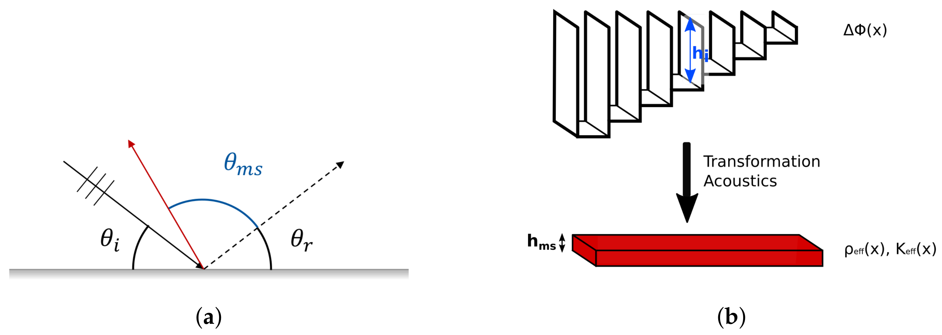
At the beginning of their development in acoustics, PGMS have been studied to overcome the Snell’s law and the law of reflection, introducing an additional term in the evaluation of the reflection/refraction angle depending on the metasurface design, as described by the Generalised Snell’s law (GSL)
Without losing generality, the equation is stated for a 1D phase delay gradient, in which
is the wavelength of the incident acoustic perturbation,
and
are the angles of the incident and transmitted fields,
and
are the refractive indexes of the incident and transmitted domains. In the case of a sound-hard boundary, where the only reflection can occur, Equation (
1) reads
where
is the reflection angle of the acoustic wave impinging on the boundary (see
Figure 1a).
In both Equations (
1) and (
2),
refers to the difference between the phase of the transmitted/reflected field from a metasurface-lined boundary and a standard one modelled by a perfectly sound-reflecting boundary
. In the following, only the case of reflection from a PGMS boundary will be considered. The typical implementation of a PGMS uses periodic arrangements of elementary cells capable of introducing a local
in the reflected field. The phase gradient profile required for the application is reproduced with a spatial definition defined by the cells’ dimensions by distributing the unit cells. Many concepts for the elementary cell and its design procedure have been proposed [
20,
21,
22,
23,
24,
25,
26]; some of these designs have complex shapes, with several parameters controlling the geometries. However, they all have been conceived using the concept of the acoustic waveguide. In fact, the easiest way to achieve a phase delay gradient in the reflected field with respect to a flat hard wall is substituting it with a sequence of rectilinear waveguides for the zeroth-order mode with tailored lengths (see
Figure 1).
The length of the tube
h can be easily linked to the phase delay achieved by a simple relation involving the wavelength
of the acoustic perturbation under consideration and the length of the extra path covered by the impinging wave, 2
h:
A metafluid can achieve the same effect through the definition of its parameters, bulk modulus and inertia tensor. The Transformation Acoustic (TA) framework can be used to establish a design procedure for a metafluid that mimics a PGMS.
Following the TA procedure [
27], the equation invariance under coordinate transformation is exploited to obtain the metafluid general governing equation for acoustic perturbations.
Let
and
be the original and the deformed (metafluid) domains, the coordinates in each configuration are
and
, respectively; the mapping
is defined by
and it is a one-to-one invertible transformation. The deformation gradient is
, or in component form
; hence, the Jacobian of the deformation is
. The polar decomposition implies
where
R is proper orthogonal and
. Being
a symmetric and divergence-free second-order tensor, the expression for the Laplacian in
in terms of derivatives in
is
Hence, the scalar wave equation governing the acoustic field in
, occupied by a homogeneous fluid with density
and bulk modulus
,
is, in the deformed region
occupied by a metafluid, replicated by
being
the metafluid bulk modulus and
𝜚 its inertia tensor.
3. Numerical Model
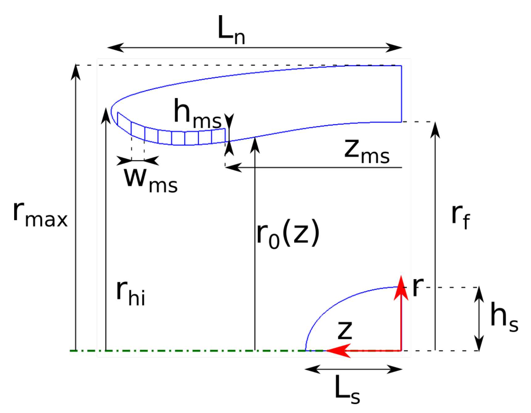
As anticipated above, the studied configuration is a 2D axial symmetric geometry representative of a modern turbofan inlet portion. Following
Figure 2, the reference engine fan radius is set
m; the sizing is completed comparing different relations presented in the literature [
30,
31,
32]:
,
,
and
. The shapes of the inlet section are built using Class Shape Transformation (CST) curves, following [
30,
33,
34].
The metalining is placed on the internal surface of the inlet, starting from with an overall length of divided into eight cells of equal width = 0.05 m. In the present study, the MS is positioned close to the lip leading edge: the treatment extends in a currently non-lined part of the nacelle as its presence in the nacelle is not intended to be an alternative to the standard absorbing liners. The effect of the positioning of the cells and the total extension of the treatment were not investigated; in future developments, further synergies between the metalinings and the classic acoustic liners may likely arise also considering these two variables.
The main focus is on the reduction of the noise radiated towards the ground from the engine inlet. For this reason, the effect of the MS device is evaluated over an arc of virtual microphones, centred on the middle of the cowling inlet section, with a radius
= 3.5 m (
). The arc extends from 20° to 120° (being 0° aligned with
z-direction in
Figure 2).
The nacelle is immersed in a quiescent barotropic, inviscid and irrotational fluid, in which the classic wave equation describes the propagation of the acoustic waves, Equation (
5). The cells occupy what is from now on called the metafluid domain, where Equation (
6) holds the solution for the acoustic pressure, with properties defined by Equation (
9). The continuity of the acoustic field is ensured at the interface between cells and the outer domain by imposing
The boundary conditions are completed with perfectly matched layers at the exterior boundaries to truncate the computational domain avoiding non-physical reflections. The internal boundaries of the cells and the walls of the nacelle are considered acoustically rigid, imposing the normal derivative of the acoustic velocity to be null.
The sound source is modelled as a boundary condition on the fan section by considering only one azimuthal mode at the BPF for the maximum rotational speed of the fan (628 Hz).
The acoustic problem is solved in the frequency domain, the SPLs at the virtual microphones have been evaluated with the commercial FEM solver Comsol
®, in which Equations (
5) and (
6), Fourier-transformed, are implemented in their integrated weak formulation and applied to the elements of the discretely meshed domain.
4. Results
An optimisation procedure is applied to the metafluid to maximise the noise reduction effect for the selected duct mode propagating in the nacelle. A generic single-objective unconstrained optimisation process can be formalised as follows,
being
the objective function with
x the vector containing the
N design variables bounded by
and
in the
design space , and
the vector of the
M environmental parameters (independent of the designer choice) in the
parameter domain . For the optimisation of the metafluid design, a merit function is defined as the integral of the acoustic pressure level over the arc of virtual receivers:
The minimisation of the objective functions is achieved through a Particle Swarm Optimization (PSO) algorithm, using a swarm with ten individuals per variable. In the proposed approach, the optimisation variables are the equivalent lengths of the cells
, bounded allowing a range of
of
for each cell, see Equation (
3). The bulk modulus and the inertia tensor of each metafluid cell are then evaluated with Equation (
9).
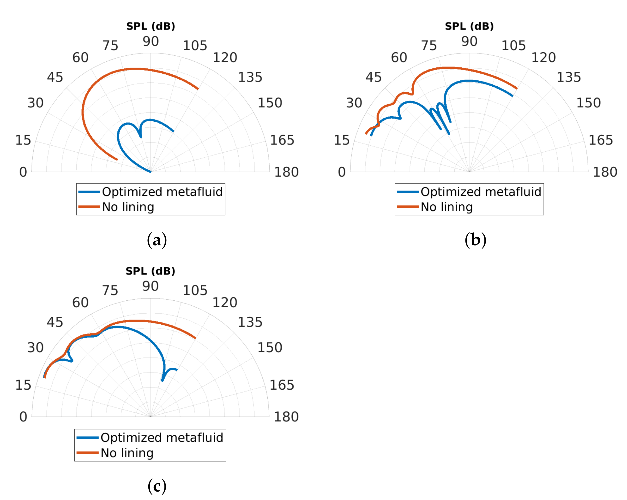
Three different duct modes are used to investigate the effect obtainable from the phase-gradient-based treatment under different incident sound fields. Specifically, results have been obtained for and , chosen as representative of low and high-order azimuthal modes. The is associated with only one radial mode with , as revealed by the numerical modal analysis at the fan section, while, among the five cut-on radial modes for , and were considered. Since the duct has a continuously varying cross-section, a preliminary check is done on the selected modes to ensure the propagation of the relative acoustic perturbation.
Figure 3 shows the SPL along the microphone arc comparing the optimised metafluids for each case/mode with the reference solution not including any lining in the duct. A dramatic reduction in the pressure level along the entire arc considered is obtained for the higher-order azimuthal mode
, while for each of the two
modes, the acoustic levels are more effectively lowered starting from
≥ 60°. These reductions cannot be ascribed to absorption by the metasurfaces since the implemented model does not consider any dissipative effect. It seems reasonable to explain the observed abatement as the effect of the boundary conditions change in the lined section, such that for
= 15, the propagation of the considered mode from the inlet section towards the external field is not allowed (evanescent), and for each of the
= 4 modes, the diffraction from the nacelle lip is strongly reduced along with the side propagation. It is not completely clear to the authors whether this interpretation may be equivalent to a redistribution of the acoustic incident field due to unconventional/extraordinary reflection.
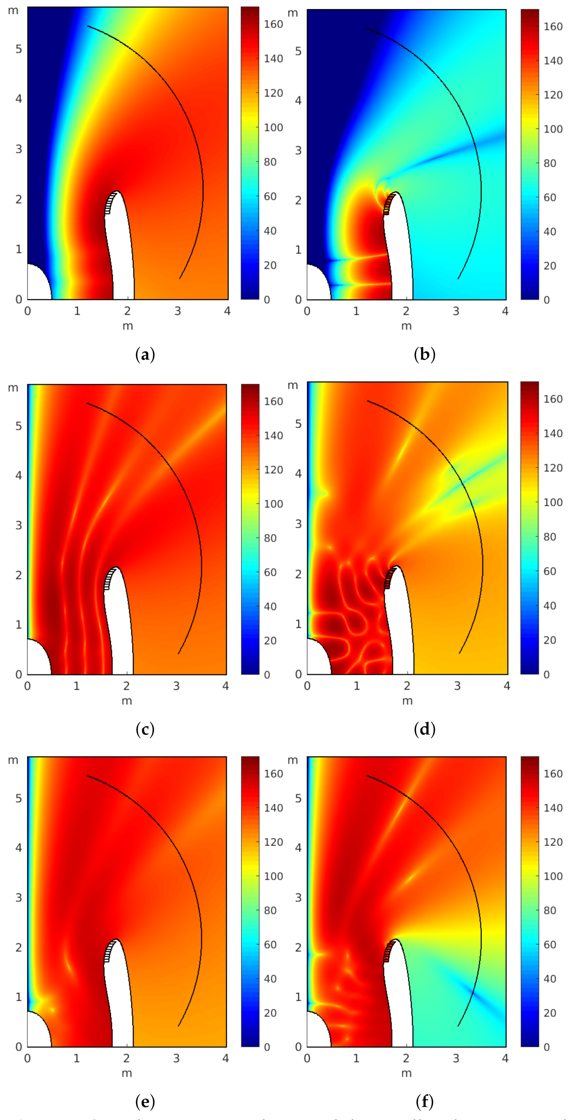
The above considerations are confirmed by the field visualization of the acoustic levels around the nacelle in
Figure 4. Acoustic energy is not effectively transmitted out of the duct for the
= 15 case,
Figure 4b, the main emission lobe is highly attenuated for the first
= 4 mode considered,
Figure 4d, and diffraction from the inlet lip is greatly reduced for both the
= 4 modes,
Figure 4f, causing the reduction in pressure levels for
≥ 60°.
The directivity modification achieved is very different among the three cases considered. It should be noted that the most effective optimised metalining is the one tackling the higher-order azimuthal mode, for which the radiated noise is almost completely eliminated. No general behaviour can be observed in the delay distributions obtained from the optimizations for the three different modes. The optimal delays and their gradients substantially differ from each other as expected, being the only common characteristic a remarkable variability of the delay along the surface.
As already mentioned, the obtained results are preliminary, although encouraging, and aiming to explore the potential of PGMS in a simplified though realistic setting, which includes some of the important features of real applications (such as surface curvatures, varying cross sections, source description). The study is far from the complete design of a liner based on the phase-gradient: metamaterial linings are not a mature technology, and an extensive analysis on their potential benefits and relative exploitation strategy is needed for a technology-readiness level advancement.
5. Conclusions
The article presents the extension of phase gradient metasurfaces’ analytical and numerical treatment as equivalent metafluids to consider axial symmetric 2.5D domains. This allows considering geometries with curved surfaces, around the symmetry axis and in the axial direction.
The metafluid model greatly helps perform a simulation-based design optimisation of a PGMS to realise innovative acoustic treatments of realistic nacelle intakes. The acoustic source included in the modelling is taken from a modal analysis of the fan section in the inlet duct.
This paper aimed to study the potential benefits of the phase-gradient technology, and is not an attempt to design a complete new liner or nacelle. Simulations appear to confirm the potential of axially non-uniform linings based on metamaterials in the abatement of noise radiated from the nacelles’ inlet, already emerged in previous numerical studies. This type of metasurface can steer the reflected field under the quasi-normal incidence of the acoustic field, as evidenced in the literature. However, the effect observed in the present configuration is probably more effectively explained by stating that the lining imposes a boundary condition changing the propagation of the tackled acoustic mode, which in some cases may become evanescent or its diffraction through the inlet section is strongly reduced. The effect is obtained through a metafluid equivalent to rectilinear channels of tailored lengths, which in principle have a purely reactive behaviour, with no energy dissipation.
The analytic model of TA broadens the concepts that can be explored to realise phase gradient metasurfaces and their effects, including all that can tune the occupied domain’s effective bulk modulus and density, such as pentamode materials.
No viscothermal acoustic phenomena are modelled in the simulations, and the effects of the aerodynamic flow and boundary layer are not considered. These effects might be considered in future developments using higher fidelity models, with a consequent non-negligible increase in the computational burden.
Optimisations for a single acoustic mode at the BPF have been presented in this work, and each resulting metafluid is not guaranteed to be effective for a different azimuthal/radial mode. Therefore, a multiobjective optimisation might be a viable strategy to extend the window of the metamaterial effectiveness, considering more modes with different axial wavenumber and azimuthal order and/or frequencies of interest. Such an enriched approach comes, however, with an increment of computational cost, linearly increasing with the number of modes/frequencies considered.
Other effects from the metalining may also be explored by using different objective functions, including enhancing the efficacy of standard liners or the virtual scarfing effect, the latter requiring a more expensive complete 3D modelling of the problem.


