Article

Experimental Studies into the Analysis Required for the Durability Assessment of 7075 and 6061 Cold Spray Repairs to Military Aircraft

1
Centre of Expertise for Structural Mechanics, Department of Mechanical and Aerospace Engineering, Monash University, Clayton, VIC 3800, Australia
2
RUAG Australia, 836 Mountain Highway, Bayswater, VIC 3153, Australia
3
Structures Division, Naval Air Systems Command, Patuxent River, MD 20670, USA
*
Author to whom correspondence should be addressed.
Aerospace 2020, 7(9), 119; https://doi.org/10.3390/aerospace7090119
Submission received: 27 July 2020 / Revised: 16 August 2020 / Accepted: 17 August 2020 / Published: 19 August 2020
(This article belongs to the Special Issue Ageing Aircraft and Additive Manufacturing)

Abstract

:
This paper presents an experimental study into the analysis required for the durability assessment of 7075 and 6061 cold spray repairs to military aircraft. To this end, it is first shown that provided the bulk stress in a 7075 cold spray coating can be kept beneath approximately 150 MPa, then the coating should not crack. A range of examples are presented in which the interface between the coating and the substrate only fails subsequent to crack growth in the substrate. We also show that failure of cold spray repaired/coated panels can also be due to the nucleation and growth of cracks in the substructure immediately adjacent to the coated/repaired region. As such, when performing a durability analysis for a cold spray repair, the growth of such small naturally occurring cracks, both at the interface and immediately adjacent to the ends of the coating, need to be accounted for.

Graphical Abstract

1. Introduction

As outlined in the detailed reviews presented in [1,2,3,4,5] and in [6,7,8,9,10,11,12,13,14,15,16,17,18,19,20,21,22], cold spray, also known as Supersonic Particle Deposition (SPD), is increasingly being used to repair military aircraft. Whilst the initial focus was on geometry restoration [1,2,3,4,5,6], attention has subsequently expanded to include its use to maintain the structural integrity of aircraft structural components [1,7,8,9,10,11,12,13,14,15,16,17,18,19,20,21,22]. However, with the exception of [1,7,8,9,10], there are currently no papers that address/illustrate how to perform the durability analysis needed to certify a cold spray repair to military aircraft. In this context, it should be noted that, as explained in MIL-STD-1530D, analysis is the key to certification and that the role of testing is merely to validate or correct the analysis. This raises the question: do the crack growth analysis cases needed for a durability analysis of a cold spray repair differ from those commonly used to assess the durability? Indeed, the question is the focal point of the present paper.
The United States Air Force (USAF) requirements for the durability and damage tolerance certification for cold spray repairs to aircraft structural parts are detailed in Structures Bulletin EZ-19-01 [23], and essentially reflect the requirements enunciated in MIL-Standard 1530D [24] and the US Joint Services Structural Guidelines JSSG2006 [25]. As noted in the recent review paper [9], which discussed a building block approach to certifying AM and cold sprayed (SPD) repaired parts, in order to meet the guidelines outlined in Structures Bulletin EZ-19-10, several questions need to be addressed, viz:
(i)
How can we accurately compute crack growth in an AM or SPD repaired part when there is a residual stress field?
(ii)
How can we accurately compute crack growth in a cold spray repair where cracking can nucleate, either in the substructure being repaired, or at the intersection between the cold spray?
(iii)
How can we accurately perform a durability analysis for a cold spray repair if there are multiple collocated cracks?
(iv)
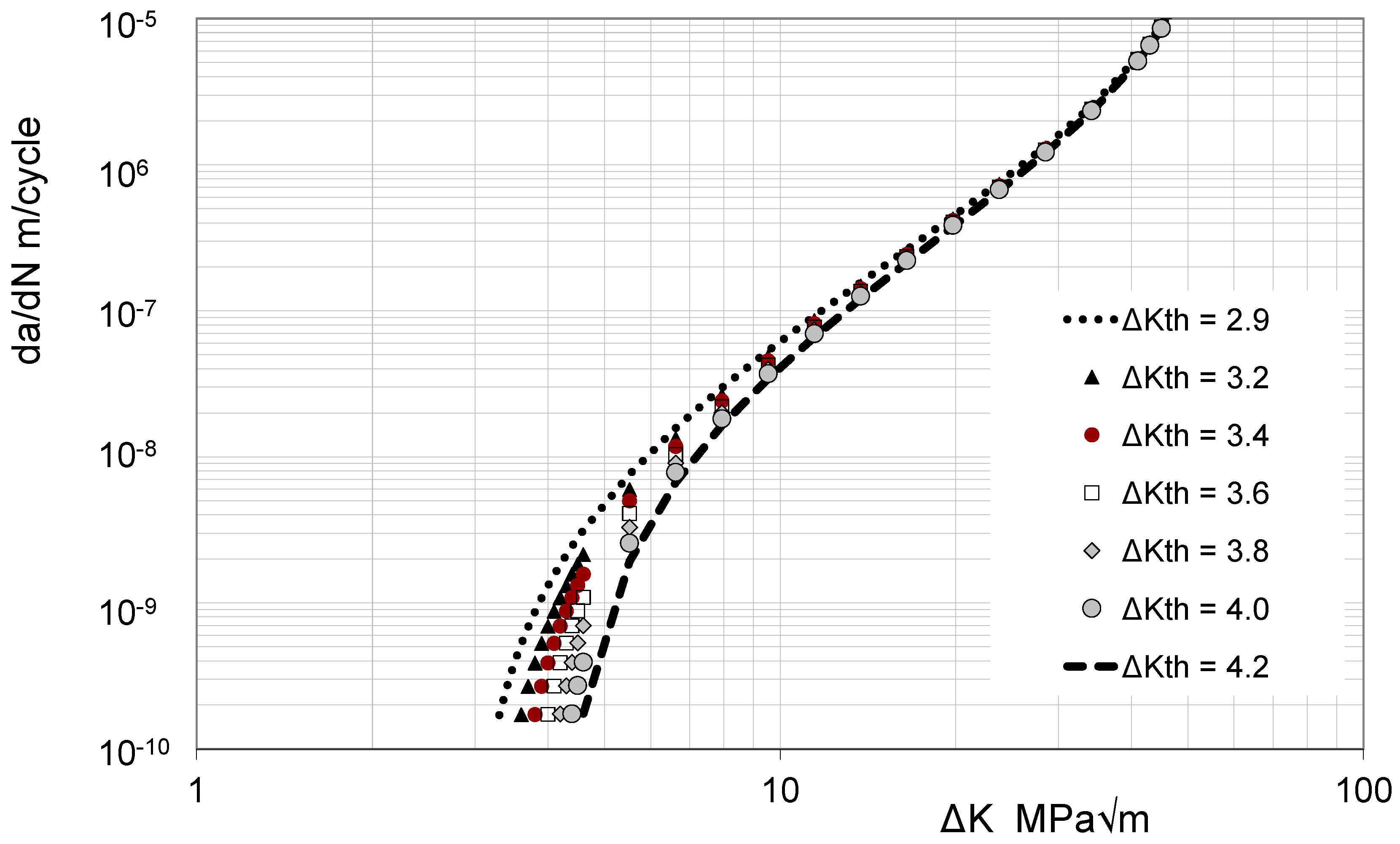
Can we relate da/dN versus ΔK equations, where da/dN is the crack growth rate per cycle and ΔK (= KmaxKmin) is the difference between the maximum and minimum values of the stress intensity factor in a load cycle, needed to perform items (i) through (iii) to the corresponding curves determined for the conventionally manufactured material? Here, a is the crack length and N is the number of cycles.
To this end, [9,10] presented a methodology that was based on the Hartman–Schijve variant of the NASGRO crack growth equation [26], which is outlined in the Appendix A, that (to some extent, and provided that the crack growth studies needed for the durability assessment are known) enables each of these questions to be answered in a fashion that is consistent with the building block approach outlined in MIL-STD-1530D [24], and presented a number of example that illustrated this approach. However, the key is to know what cracking needs to be analysed as part of the durability assessment. In this context, it is clear that if the durability assessment does not address the actual cracking seen in the part being assessed, then the analysis will be of little use. Experience with cold spray repairs to fatigue critical parts in operational aircraft has shown that there can be several possible failure mechanisms. For example, in the SPD (cold spray) repair example presented in [9], which was a repair to intergranular corrosion at a fastener hole in a Royal Australian Air Force (RAAF) P3C Orion wing skin, the cracks nucleated from a material discontinuity at the bore of a fastener hole. This meant that the (nucleating) crack was exposed to the environment–in this case, laboratory air. Since, as shown in [13,14,15,19,20,21], cracks that determine the fatigue life in cold spray repairs can nucleate, and subsequently grow, from small sub mm internal material discontinuities in the substrate at the intersection of the cold spray coating with the substrate, such cracks may not be exposed to the environment. This is an important distinction since, as explained in [14], such cracks grow in a “vacuum-like” environment and, therefore, as per [27,28,29,30], grow much slower than if they could “see” the environment. As such, the growth of these interior cracks, which nucleate in the substrate at the intersection of the cold spray, will be much slower than interfacial cracks that can “see” the environment. The current paper presents a series of experimental studies that reveals the importance of this phenomena, i.e., failure due to cracking that nucleates from material discontinuities in the substrate at the interface between the cold spray and the substrate. At this stage, it should be noted that the growth of small naturally occurring lead cracks, i.e., the cracks that determine the operational life of a component [31,32,33], which see the environment often grow in a near exponential fashion [26,31,32,33,34,35,36,37] and follow a da/dN versus ΔK curve that is essentially a Paris-like crack growth equation with a small fatigue threshold. Furthermore, for small cracks growing in laboratory air, there are minimal R ratio effects [26,30,37,38,39,40,41,42]. (The relationship between the long crack and the small crack da/dN versus ΔK curves, for cracks that are growing in air, is discussed in [38].) However, as discussed in [14,43,44], for small cracks growing in a vacuum, there appears to be a well-defined (non-zero) threshold. Nevertheless, it appears that for such small interior cracks, the crack growth rate (da/dN) can be expressed as a function of (ΔK − ΔKthr) [43], where ΔKthr is the fatigue threshold.
Structures Bulletin EZ-19-01 [23] stresses the importance of analysis in the durability/economic life assessment of AM and AM repairs, such as cold spray (SPD) and laser-assisted deposition, and mandates the use of a minimum equivalent initial damage size (EIDS) of 0.254 mm. This size EIDS is taken from JSSG2006 [25]. A problem faced in the durability analysis needed for the certification of cold spray repairs is how can the necessary small crack da/dN versus ΔK curve be determined. It is tempting to use the approach proposed in [17], whereby a small sub mm notch is cut into a specimen. Unfortunately, there are numerous problems with this approach. In this context, it should be noted that the paper by Virkler and Hillbery [45] is acknowledged as the seminal paper that established the degree of scatter seen in da/dN versus ΔK tests performed to the fatigue test standard ASTM E647-13a [46]–see Figure 1. Other examples of this non-uniqueness, i.e., the variability in the da/dN versus ΔK curves for a conventionally manufactured material, are given in [47,48].
It has long been known [26,37,38,47,48,49,50,51,52] that the degree of scatter associated with small naturally occurring cracks is significantly greater than that seen for long cracks. As such, the test protocol used in [17], which involved a limited number of tests (two) on artificial notches with lengths that varied from 0.15 to 0.2 mm, should not necessarily be thought of as generating the small crack growth data needed to perform the durability analysis required for the certification of cold spray parts, or cold spray repairs. This is reflected by the fact that in the near-threshold region, the da/dN versus ΔK curves presented in Figure 5a in [17] for what are termed long and short cracks in annealed cold spray 6061 are essentially identical, and lie within the scatter band that could be expected for the growth of long cracks [45,47]. Furthermore, since these tests were performed in a laboratory environment, the da/dN versus ΔK curves reported in [17] are also unlikely to be representative of those associated with cracks that nucleate beneath the surface of the cold spray (SPD) where the crack does not see the environment.
To illustrate the (potential) scatter associated with the growth of small/short cracks in conventionally manufactured 6061, it is pertinent to note the crack growth histories reported in [53,54]. Whereas [53] specifically stated that the crack growth was exponential, and that the crack rate da/dN was proportional to the crack length, a similar statement was not made in [54]. However, on plotting the crack growth history associated with the fastest crack reported in [54], it can be seen that crack growth was essentially exponential–see Figure 2. Hence, as a first approximation, the crack growth rate was essentially proportional to the crack length. As such, it follows that for these tests, the crack growth rate da/dN should be able to be approximated by a simple Paris-like power law with a low fatigue threshold and, as per [26,36,55,56], an exponent of (approximately) 2. As such, unlike the crack growth curves given in [17], the 6061 small/short crack growth data presented in [53,54] is consistent with the USAF Durability Design Handbook [34] and the USAF approach to assessing the economic life of military aircraft [35].
With this in mind, the purpose of the present paper is to shed light on the growth of small cracks in tests on specimens with cold spray (SPD) deposits on AA2024-T3, AA7075-T6, AA7075-T7351 and AA7050-T7451 substructures. A range of examples are presented in which the interface between the SPD and the substrate only fails subsequent to crack growth in the substrate. This failure mechanism is similar to those seen in [13,14,15,19,20,21], in that they involve the nucleation and subsequent growth from small material discontinuities in the substructure, at the intersection between the cold spray and the substructure, followed by delamination at the SPD to substrate interface. We also show that failure of cold spray repaired/coated panels can be due to the nucleation and growth of cracks in the substructure immediately outside of the coated/repaired region. As such, when performing a durability analysis for a cold spray repair, the growth of such small naturally occurring cracks, both at the interface and immediately adjacent to the ends of the coating, need to be accounted for. In the case of through thickness cracks in thin skins with cold spray coating, it should be noted that closed-form analytical solutions for through thickness cracks repaired using cold spray were first given in [11].

2. Fatigue Tests on 7075 Powder SPD Doublers on 2024-T3 Specimens

A series of constant amplitude fatigue tests, at a load ratio of R = 0.1, were performed on 3.175 mm thick 2024-T3 dogbone specimens, with a geometry as shown in Figure 3. The tests were performed in an MTS 100 kN servo-hydraulic machine in accordance with the American Society Testing and Materials (ASTM) tests standard E 739-80 [57]. The effect of two different coating thicknesses, namely 0.1 and 0.5 mm, was evaluated and tests at a number of load levels were performed. The resultant stress life curve is shown in Figure 4 together with data obtained from tests on panels without a cold spray coating, and for one specimen that was not coated, which was grit blasted prior to testing at a stress in the working section of 225 MPa, which corresponds to a load of approximately 30.00 kN. The grit blasting (surface preparation) process used was the same as that used for all cold spray applications to Royal Australian Air Force aircraft [16], and the application parameters are as outlined in [11]. Indeed, this combination of surface treatment and application parameters is used in all of the cold spray examples discussed in this paper. Since it is common practice for aerospace skins to be surface treated so as to minimise the effect of corrosion, Figure 4 also presents the stress life curves given in [58] for tests on chromic anodized 2024-T3.
A key point to be noted in Figure 4 is that below a stress of approximately 150 MPa, there was no failure. There was also no cracking in the 7075 coating, or delamination of the coating from the 2024-T3 substrate. To illustrate this, Figure 5 presents a picture of the stress range of the bulk stresses field (Δσ1 + Δσ2 + Δσ3), which is the first invariant of the stress tensor, obtained using infra-red thermography, in a 7075 coating of a specimen that was tested at a stress corresponding to approximately 150 MPa, that did not fail after more than 3,000,000 cycles. Here, Δσ1, Δσ2, and Δσ3 are the ranges of the three principal stresses, namely σ1, σ2, and σ3, in a cycle. (The test was stopped after approximately 3,000,000 cycles.) This picture reveals that there was no cracking in the coating.
To further illustrate this, Figure 6 presents a picture of the bulk stress field at 2,293,500 cycles in a specimen tested at a stress of approximately 169 MPa. This test was terminated shortly thereafter due to failure of the pump. This picture also reveals that there was no cracking in coating.
Figure 7 and Figure 8 show the failure surface associated with specimen number S24, which had a 0.5 mm thick 7075 coating and which failed at 114,344 cycles, and specimen S22 which failed at 122,521 cycles. In both cases, we see that cracks in the 2024-T3 nucleated at multiple locations at the intersection between the 7075 coating and the 2024-T3 substructure. The growth of these (multiple) cracks subsequently led to delamination of the coating from the 2024-T3. Also note the intact nature of the interface on the opposing (uncracked) surface. This phenomenon, i.e., failure due to the nucleation and growth of multiple cracks in the 2024-T3 at the interface between the 2024-T3 and the coating, was seen in all cases.
A similar phenomenon, i.e., that the cold spray (SPD) coating could withstand significant cracking in the 2024-T3 skin, was seen also in tests on 7075 powder SPD repairs to fuselage lap joints seen in Boeing B737 and B727 aircraft [12]. In [12], it was found that cracking and delamination in the 7075 coating only arose after the cracks in the 2024-T3 fuselage skin had reached a length of approximately 6 mm. The cracking in the coating arose as it attempted to carry the load shed from the 2024-T3 skin [12]. Furthermore, as reported in [12], the cracking in the coating often lay on a different plane to that of the cracking in the 2024-T3. In other words, the crack from the 2024-T3 did not grow into the cold spray.
This phenomenon was also seen in the current fatigue test program–see Figure 9 and Figure 10, where we see both delamination of the 7075 coating from the 2024-T3–which arose as a result of failure in the 2024-T3 substrate, and the fact that the failure of the coating was frequently associated with a different plane to that of the cracking in the 2024-T3 substrate.

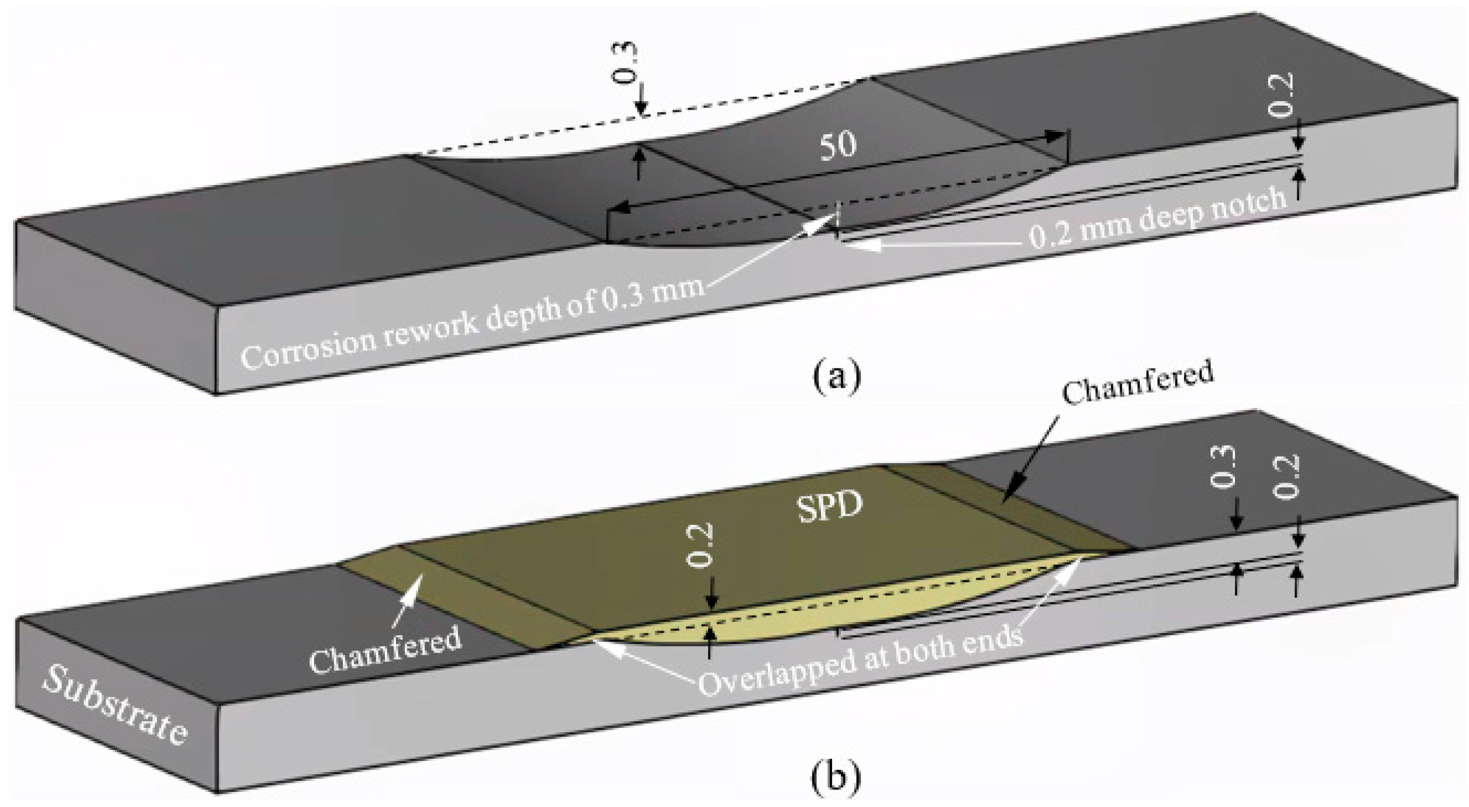
3. Repair of Simulated Corrosion in 7075-T7351 Panels

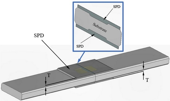
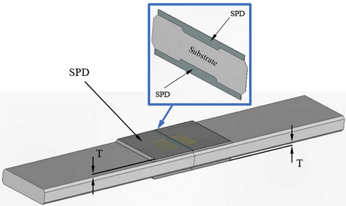
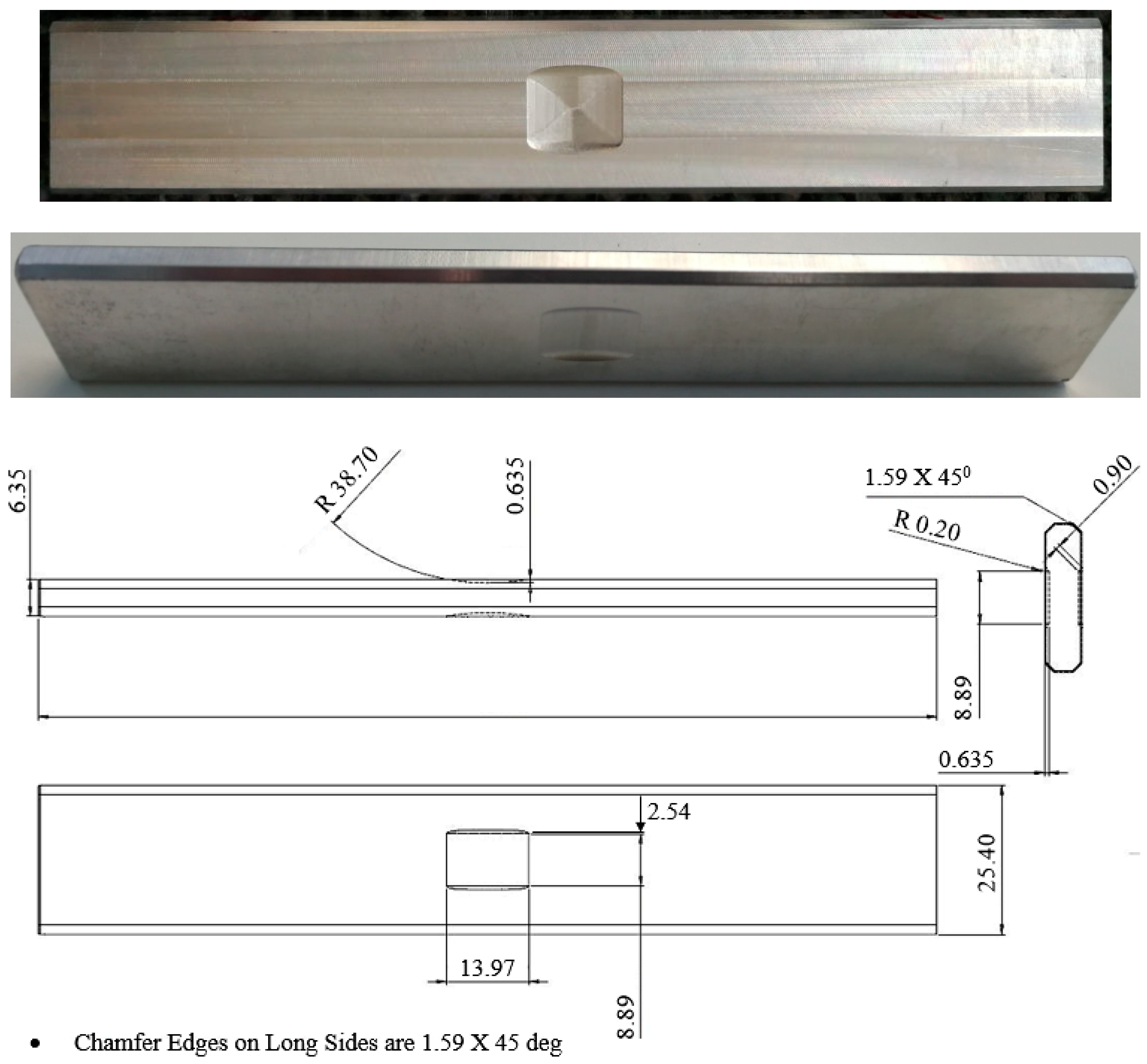
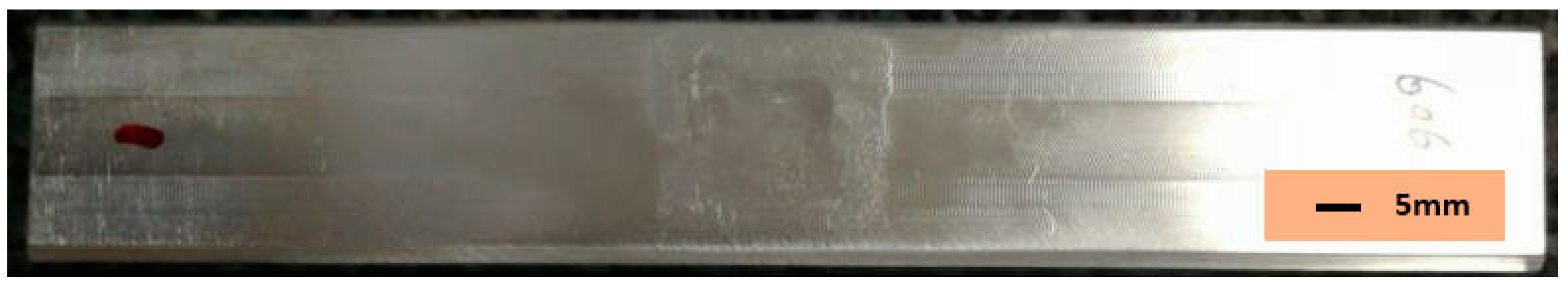
3.1. Test Specimen Geometry and Dimensions

To continue this study, we tested SPD (cold spray) repairs to a simulated corrosion rework in a 7075-T7351 skin. The geometry of the test specimen is as shown in Figure 11, and a typical repaired specimen is shown in Figure 12. A total of 16 specimens were tested–see Table 1. The tests were performed at a maximum load of 38.1 kN and R = 0.1. This corresponds to a maximum remote stress of approximately 240 MPa. The cold spray coatings evaluated in this study were 7075, 6061, and ceramic particles in a 6061 aluminium matrix, which in this study is referred to as AMC.
Prior to fatigue testing, lock-in thermography (infra-red) stress pictures were taken both for the unrepaired specimens and for the specimens with 7075, 6061 and AMC SPD coatings. A typical infra-red bulk stress picture is shown in Figure 13. These figures revealed that the application of the coatings resulted in the specimens having a near uniform stress field. In other words, the coating had (essentially) removed the stress concentration due to the simulated corrosion cut.

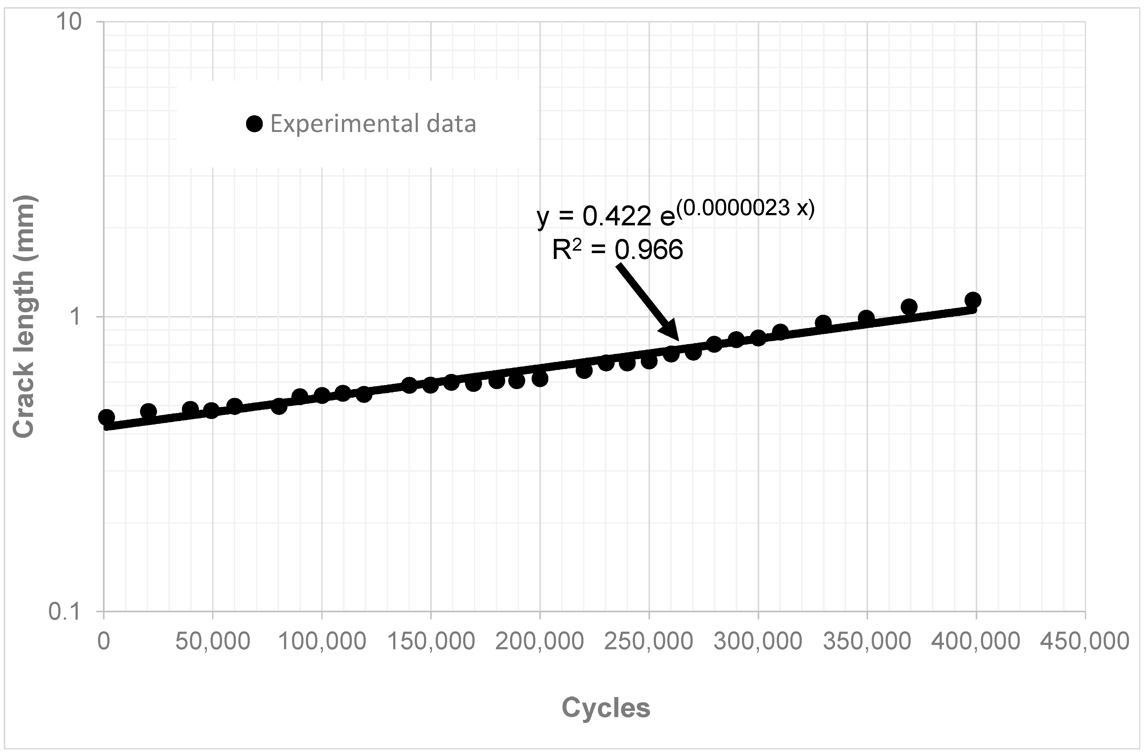
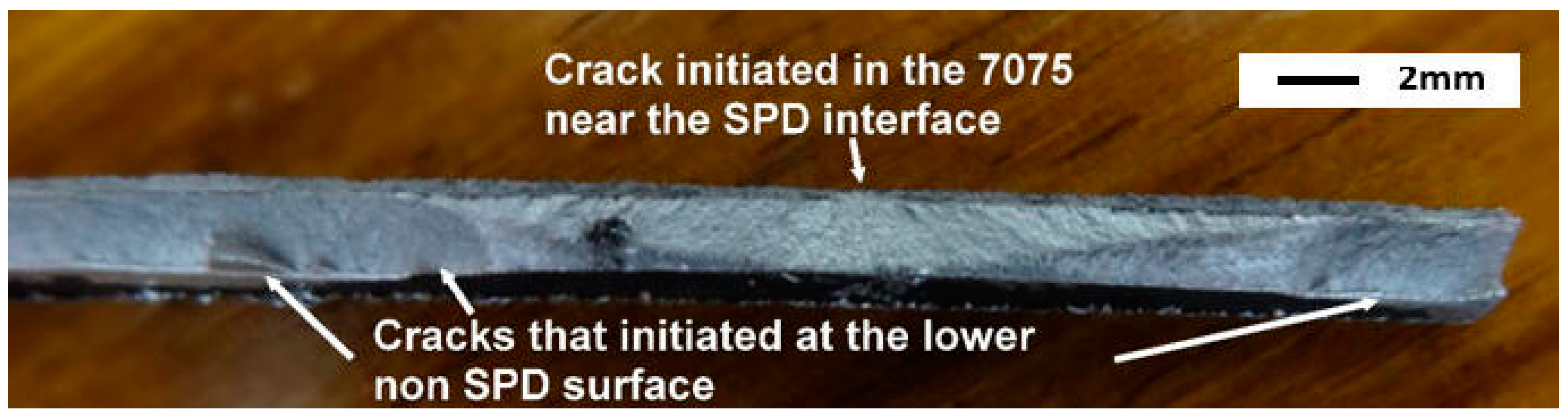
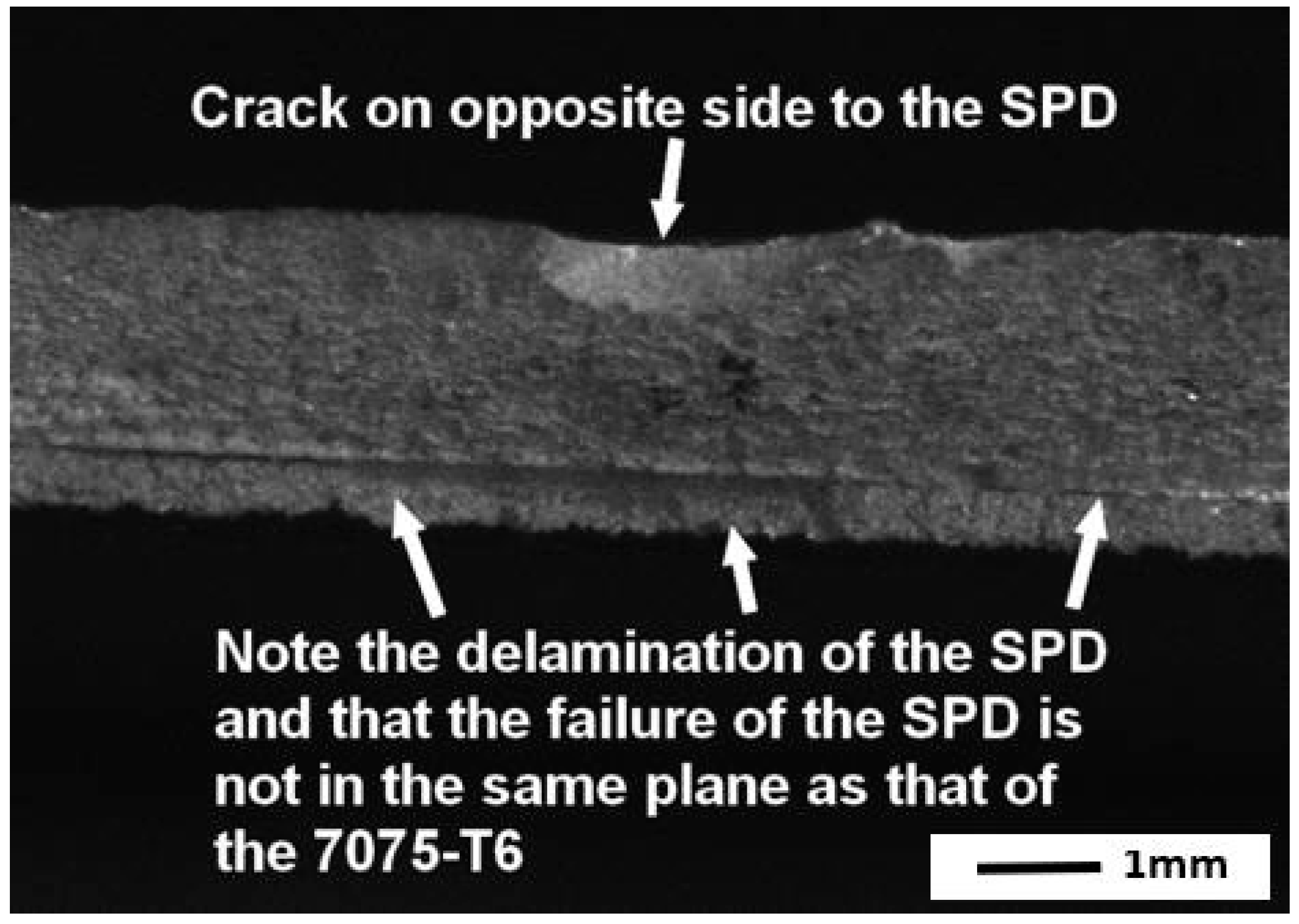
3.2. Fatigue Test Results

The test lives associated with these specimens are listed in Table 1. Table 1 reveals that the baseline specimens had the longest test lives. Of the repaired specimens, the non-heat-treated 6061 doubler specimens had the longest fatigue lives. The mean fatigue lives of specimens with non-heat-treated 7075 coatings, heat-treated 7075HT, AMC and AMC LT-NGB were approximately 77.6%, 38%, 43.3%, and 60% of that seen by specimens with a non-heat-treated 6061 SPD coating (doubler). Heat treatment of the 7075 coating significantly reduced the fatigue life. Typical failure surfaces are shown in Figure 14, Figure 15, Figure 16, Figure 17 and Figure 18. All of the specimens failed as a result of the nucleation of multiple cracks in the 7075-T7351 substrate at the intersection between the coating and the substrate. This failure mechanism is identical to that seen in the previous studies.
Here it should be noted that, despite the stress in the 7075 coating exceeding 150 MPa, failure did not initiate in the coating.

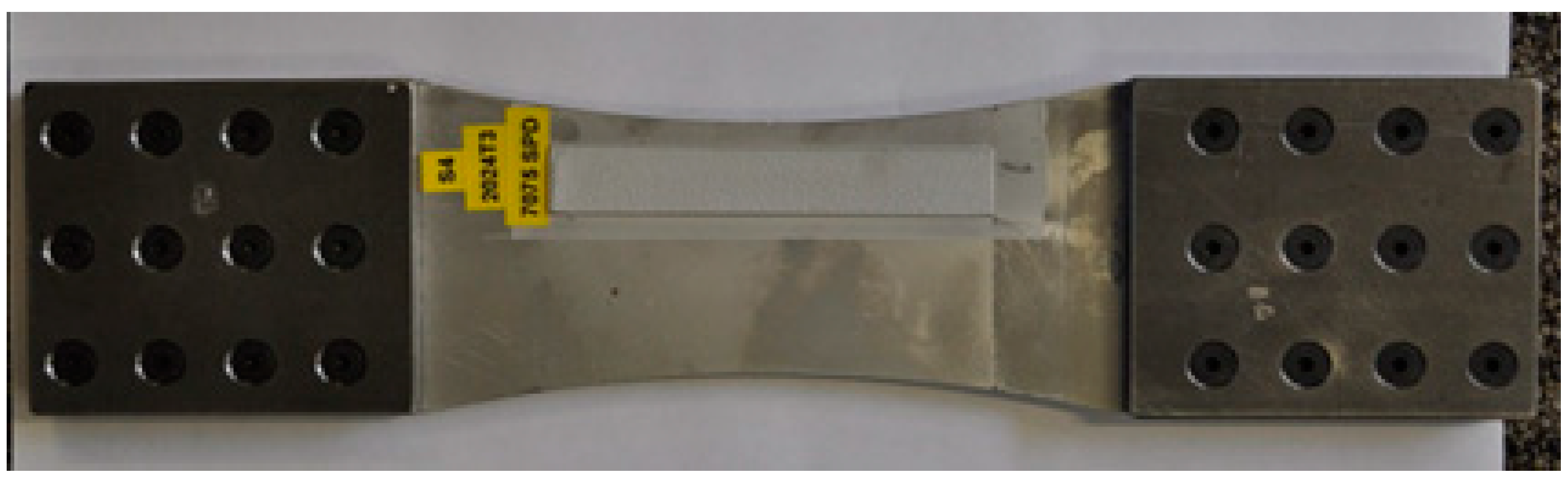
3.3. Repair of Simulated Corrosion in a 7075-T6 Panel

It is pertinent to compare the results of the previous study with those seen in a study [11,12] on cold spray repairs to corrosion damage in AA7075-T6. The geometry of the specimens tested [11,12] is shown in Figure 19. As can be seen in Figure 20 and Figure 21, for a specimen subjected to a remote maximum load of 35 kN, which failed at 640,000, crack nucleation occurred at multiple locations in the 7075-T6 substructure at the intersection between the 7075 coating and the 7075-T6, and also on the opposing face that did not have a 7075 coating/repair. The growth of these cracks also subsequently led to delamination of the coating. However, crack initiation and growth also occurred on the surface of the specimen where there was no coating–see Figure 20 and Figure 21. The sizes of the nucleating defects at these two opposing sites were similar.

4. Damage Tolerance of SPD Repaired Specimens

The paper by Jones et al. [11] was one of the first to illustrate the damage tolerance of cold spray coatings and repairs. To this end, [11] presented the results of constant amplitude tests on a 350 mm (long) by 60 mm wide 1.27 mm thick 2024-T3 clad aluminum alloy single-edge notch (SENT) test specimen with a 2 mm long edge crack. The maximum and minimum stresses in the tests were σmax = 181 MPa and σmin = 18.1 MPa respectively. Two tests were performed, viz a baseline specimen that did not have a 7075 coating, and a specimen that had a 1 mm thick full-width 7075 coating on both sides of the 2024-T3 specimen. Whilst the baseline specimen (no coating) failed at approximately 35,000 cycles, the 7075 coated panel was stopped test after approximately 70,000 cycles with no evident delamination damage or cracking in the 7075 coating, or crack growth in the 2024-T3 skin. (It should be noted that in [11] only the result up to 60,000 cycles was reported. An additional 10,000 cycles were subsequently completed to ensure a life factor of two.) As reported in [11], there was no crack growth in either the 2024-T3 or the 7075 coating and no delamination of the coating from the 2024-T3.
To further illustrate that cracking in the coating and delamination can be controlled by the appropriate choice of the thickness of the coating, [12] presented the results of a study into a 7075-T6 specimen with a 4.76 mm (3/16 inch) universal dome head fastener that contained a 1.27 mm long initial crack, in a 30 mm wide 4 mm thick and 400 mm long panel that was sprayed with a 1 mm thick 7075 coating. The specimens were subjected to a USAF C-141 military transport spectrum with a peak remote stress in the spectrum of 200 MPa. To avoid cracking in the coating, the thickness of the coating was designed to keep the maximum stress in the coating beneath 133 MPa. The tests were stopped after approximately 19,000 flights, as there was no apparent cracking or delamination in the coating, or crack growth in the 7075-T6 skin. This result is consistent with the observation reported Section 2 that below a stress of approximately 150 MPa, there should be no cracking in a 7075 coating.
The damage tolerance of an appropriately designed and applied coating, specifically its ability to resist cracking and delamination, was further illustrated in [11] that studied the ability of a 10 mm wide and 1 mm thick 7075 SPD strip, with a triangular cross section, to retard the growth of a 3.2 mm long edge crack in a 1.27 mm thick 2024-T3 aluminum alloy specimen–see Figure 22. The 7075 strip was deposited a distance of 5 mm from the edge of the specimen–see [11] for more details. The specimen was subjected to a cyclic stress, in the working section, of approximately 53 MPa and R = 0.1–see [11]. The stress images given in [11] revealed that the stresses in the 7075 strip were significantly less than 150 MPa, i.e., less than the endurance level of the 7075 coating. Furthermore, despite the crack continuing to grow beneath the 7075 strip, there was no evidence of cracking or delamination of the 7075 strip and failure initiated in the 2024-T3 at the ends of the strip–see Figure 23. This indicated that the 7075 deposition was more damage tolerant than the baseline 2024-T3 material. This test program was the first to highlight that the durability assessment of cold spray repairs needs to consider cracking in the substrate adjacent to a repair that can arise due to a cold spray deposition.

5. Conclusions

The examples presented in this study illustrate that provided the stress in a 7075 SPD (cold spray) coating can be kept beneath approximately 150 MPa, then the coating should not crack or delaminate. On the other hand, we have seen that the failure in tests on 7075 cold spray coated 2024-T3 specimens is often as a result of the nucleation of multiple small cracks in the substrate at the intersection between the coating and the substrate. This failure mechanism is also seen in 7075 cold spray repairs to simulated corrosion damage in both 7075-T6 and 7075-T7351 specimens, and in 6051 cold spray repairs to simulated corrosion damage in 7075-T7351 specimens. In this context, we have seen that:
(a)
The post heat treatment of the 7075 powder coatings significantly reduced the fatigue life of repaired 7075-T7351 specimens. It is hypothesised that this may be due to its effect on the residual stresses in the repaired specimen.
(b)
When compared to the use of 7075 and 6061 powders, the use of AMC powder to repair simulated corrosion in the 7075-T7351 specimen tests led to lower fatigue lives.
We have also seen that failure of cold spray repaired/coated panels can be due to the nucleation and growth of cracks in the substructure immediately adjacent (outside) to the coated/repaired region.
It follows from these studies that a durability analysis of a cold spray repair needs to be able to account for the growth of such small naturally occurring cracks, particularly the growth of the lead cracks both in the substructure outside the repair and in the substructure at the intersection between the repair/coating and the substructure, under the flight load spectra of interest. In this context, to meet the requirements delineated in Structures Bulletin EZ-SB-19-01 [22] and MIL-STD-1530D [23], the analysis tools must first be shown to be able to account for the growth of small naturally occurring cracks, in the unrepaired structure, under this flight load spectrum.
It should also be noted that in several of these studies, the cold spray repair did not significantly enhance the fatigue life of the structure. How to overcome this shortcoming will be explained in a subsequent paper.

Author Contributions

Conceptualisation and initial analysis, R.J.; experimental testing, D.P.; specimen manufacture and review of the final manuscript, N.M.; initial draft preparation, R.K.S.R.; overview of the paper and its relationship to aircraft certification, N.P. All authors have read and agreed to the published version of the manuscript.

Funding

This work was funded by the US Navy, Naval Air Systems Command (NAVAIR).

Conflicts of Interest

The authors declare no conflict of interest.

Appendix A. The Hartman–Schijve Variant of the Nasgro Crack Growth Equation

The Nasgro crack growth equation [59] takes the form:
da/dN = DKeff)(m-p)Keff − ΔKeff,thr))p/(1 − (Kmax/A))
where D, m, p, A and ΔKeff,thr are constants, and ΔKeff is an effective stress intensity factor, which, as per Elber [60], can be expressed in terms of a function U(R), viz:
ΔKeff = U(R) (ΔK)
where ΔK is the range in the stress intensity factor seen in a load cycle, and U is a function of the R ratio. (In [60], the term ΔKeff was introduced to enable the various R ratio-dependent da/dN versus ΔK curves to collapse onto a single da/dN versus ΔKeff curve.) Setting m = p and q = p/2, we see [26] that Equation (A1) reduces to the Hartman–Schijve crack growth equation, viz:
da/dN = DKeff − ΔKeff,thr))p/(1 − (Kmax/A))p/2
For cracks that grow from small naturally occurring material discontinuities, there is often little crack tip shielding [26,37,38,39,46,53,54,61], so that ΔKeff asymptotes to ΔK [26,53,54] and Equation (A3) reduces to
da/dN = Dκ)p2
where the crack driving force Δκ is as defined by Schwalbe [62], viz:
da/dN = DK − ΔK,thr))/√(1 − (Kmax/A))
A feature of this formulation is that it has been shown to be able to accurately perform durability analyses for unrepaired airframes, as well as for cold spray repaired and lased added deposition (LAD) repairs [1,9,26,37,39,63,64,65].

References

  1. Jones, R.; Matthews, N.; Baker, A.; Champagne, V. Aircraft Sustainment and Repair; Butterworth-Heinemann Press: Oxford, UK, 2018; ISBN 978008100548. [Google Scholar]
  2. Champagne, V., Jr.; Matthews, N.; Champagne, V., III. Chapter 14: Introduction to Supersonic Particle Deposition. In Aircraft Sustainment and Repair; Jones, R., Matthews, N., Baker, A., Champagne, V., Eds.; Butterworth-Heinemann Press: Oxford, UK, 2018; pp. 799–844. ISBN 9780081005408. [Google Scholar]
  3. Matthews, N. Chapter 15: Additive Metal Technologies for Aerospace Sustainment. In Aircraft Sustainment and Repair; Jones, R., Matthews, N., Baker, A., Champagne, V., Eds.; Butterworth-Heinemann Press: Oxford, UK, 2018; pp. 845–862. ISBN 9780081005408. [Google Scholar]
  4. Bagherifard, S.; Guagliano, M. Fatigue performance of cold spray deposits: Coating, repair and additive manufacturing cases. Int. J. Fatigue 2020, 139, 105744. [Google Scholar] [CrossRef]
  5. Champagne, V.; Helfritch, D. Critical Assessment 11: Structural repairs by cold spray. Mater. Sci. Technol. 2015, 31, 627–634. [Google Scholar] [CrossRef]
  6. Leyman, P.F.; Champagne, V.K. Cold Spray Process Development for the Reclamation of the Apache Helicopter Mast Support, Army Research Laboratory, ARL-TR-4922. August 2009. Available online: https://apps.dtic.mil/sti/pdfs/ADA505530.pdf (accessed on 9 July 2020).
  7. Jones, R.; Matthews, N.; Peng, D.; Phan, N.; Nguyen, T. Chapter 16, Applications of SPD to enhance the structural integrity of corroded airframes. In Aircraft Sustainment and Repair; Jones, R., Matthews, N., Baker, A., Champagne, V., Eds.; Butterworth-Heinemann Press: Oxford, UK, 2018; pp. 863–905. ISBN 9780081005408. [Google Scholar]
  8. Jones, R.; Peng, D.; Matthews, N. Chapter 18, Multiplicative Manufacturing and Aircraft Sustainment. In Aircraft Sustainment and Repair; Jones, R., Matthews, N., Baker, A.A., Champagne, V., Jr., Eds.; Elsevier Butterworth-Heinemann Press: Oxford, UK, 2018; pp. 931–938. ISBN 9780081005408. [Google Scholar]
  9. Kundu, S.; Jones, R.; Peng, D.; Matthews, N.; Alankar, A.; Singh, R.K.R.; Huang, P. Review of Requirements for the Durability and Damage Tolerance Certification of Additively Manufactured Aircraft Structural Parts and AM Repairs. Materials 2020, 13, 1341. [Google Scholar] [CrossRef] [Green Version]
  10. Jones, R.; Matthews, N.; Green, R.; Peng, D. On the potential of supersonic particle deposition to repair simulated corrosion damage. Eng. Fract. Mech. 2015, 137, 26–33. [Google Scholar] [CrossRef]
  11. Jones, R.; Matthews, N.; Rodopoulos, C.A.; Cairns, K.; Pitt, S. On the Use of Supersonic Particle Deposition to Restore the Structural Integrity of Damaged Aircraft Structures. Int. J. Fatigue 2011, 33, 1257–1267. [Google Scholar] [CrossRef]
  12. Jones, R.; Molent, L.; Barter, S.; Matthews, N.; Tamboli, D. Supersonic Particle Deposition as a Means for Enhancing the Structural Integrity of Aircraft Structures. Int. J. Fatigue 2014, 68, 260–268. [Google Scholar] [CrossRef]
  13. White, B.; Story, W.; Brewer, L.; Jordon, J.B. Fatigue behaviour of fastener holes in high-strength aluminum plates repaired by cold spray deposition. Fatigue Fract. Eng. Mater. Struct. 2020, 43, 317–329. [Google Scholar] [CrossRef]
  14. Jones, R. Synchrotron radiation microcomputed tomography for assessing internal cracks in cold spray repairs. Fatigue Fract. Eng. Mater. Struct. 2020, 43, 431–432. [Google Scholar] [CrossRef]
  15. Yandouzi, M.; Gaydos, S.; Guo, D.; Ghelichi, R.; Jodoin, B. Aircraft Skin Restoration and Evaluation. J. Therm. Spray Technol. 2006, 23, 1281–1290. [Google Scholar] [CrossRef]
  16. Sample, C.M.; Champagne, V.K.; Nardi, A.T.; Lados, D.A. Factors Governing Static Properties and Fatigue, Fatigue Crack Growth, and Fracture Mechanisms in Cold Spray Alloys and Coatings/Repairs: A Review. Addit. Manuf. 2020, 36, 101371. [Google Scholar] [CrossRef]
  17. Gavras, A.G.; Lados, D.A.; Champagne, V.K.; Warren, R.J.; Singh, D. Small Fatigue Crack Growth Mechanisms and Interfacial Stability in Cold-Spray 6061 Aluminum Alloys and Coatings. Met. Mater. Trans. A 2018, 49A, 6509–6520. [Google Scholar] [CrossRef] [Green Version]
  18. Ghelichi, R.; MacDonald, D.; Bagherifard, S.; Jahed, H.; Guagliano, M.; Jodoin, B. Microstructure and fatigue behavior of cold spray coated Al5052. Acta Mater. 2012, 60, 6555–6561. [Google Scholar] [CrossRef]
  19. Moridi, A.; Hassani-Gangaraj, S.M.; Vezzú, S.; Trško, L.; Guagliano, M. Fatigue behavior of cold spray coatings: The effect of conventional and severe shot peening as pre-/post-treatment. Surf. Coat. Technol. 2015, 283, 247–254. [Google Scholar] [CrossRef]
  20. Price, T.S.; Shipway, P.H.; McCartney, D.G. Effect of Cold Spray Deposition of a Titanium Coating on Fatigue Behavior of a Titanium Alloy. J. Therm. Spray Technol. 2006, 15, 507–512. [Google Scholar] [CrossRef]
  21. Cizek, J.; Matejkova, M.; Dlouhy, I.; Siska, F.; Kay, C.M.; Karthikeyan, S.J.; Kuroda, S.; Kovarik, O.; Siegl, J.; Loke, K.; et al. Influence of Cold-Sprayed, Warm-Sprayed, and Plasma-Sprayed Layers Deposition on Fatigue Properties of Steel Specimens. J. Therm. Spray Technol. 2015, 25, 758–768. [Google Scholar] [CrossRef] [Green Version]
  22. Ibrahim, M.E.; Zhang, W.Z.L. Nondestructive inspection of fatigue crack propagation beneath supersonic particle deposition coatings during fatigue testing. Int. J. Fatigue 2017, 102, 149–157. [Google Scholar] [CrossRef]
  23. Structures Bulletin EZ-SB-19-01. Durability and Damage Tolerance Certification for Additive Manufacturing of Aircraft Structural Metallic Parts; Wright Patterson Air Force Base: Montgomery, OH, USA, 2019; Available online: https://daytonaero.com/usaf-structures-bulletins-library/ (accessed on 2 February 2020).
  24. MIL-STD-1530D. Department of Defense Standard Practice Aircraft Structural Integrity Program (ASIP). 13 October 2016. Available online: http://everyspec.com/MIL-STD/MIL-STD/download.php?spec=MIL-STD-1530D (accessed on 2 February 2020).
  25. Department of Defense Joint Service Specification Guide, Aircraft Structures, JSSG-2006, October 1998. Available online: http://everyspec.com/USAF/USAF-General/JSSG-2006_10206/ (accessed on 2 February 2020).
  26. Jones, R. Fatigue crack growth and damage tolerance. Fatigue Fract. Eng. Mater. Struct. 2014, 37, 463–483. [Google Scholar] [CrossRef]
  27. Schijve, J. Fatigue crack growth, physical understanding and practical application. Fatigue Fract. Eng. Mater. Struct. 2009, 32, 867–871. [Google Scholar] [CrossRef]
  28. Kirby, B.R.; Beevers, C.J. Slow fatigue crack growth and threshold behaviour in air and vacuum of commercial aluminium alloys. Fatigue Eng. Mater. Struct. 1979, 1, 203–215. [Google Scholar] [CrossRef]
  29. Petit, J.; Ranganathan, N.; de Fouquet, J. Vacuum Effect on Propagation at Fatigue Crack Low Rate, Fracture and Fatigue: Elasto-Plasticity, Thin Sheet and Micromechanisms Problems, Proceedings of the Third Colloqium on Fracture, ECF 3, London, UK, 8–10 September 1980; Radon, J., Ed.; Elsevier: Oxford, UK, 1980; pp. 329–337. ISBN 0-08-026161-2. Available online: https://books.google.com.au/books?id=_jkvBQAAQBAJ&pg=PA329&lpg=PA329&dq=Petit+Vacuum+effect+on+fatigue+crack+propagation&source=bl&ots=OPiIUu29IJ&sig=ACfU3U3MGo1vbmnH1gUczwoTv-LDCaeo6Q&hl=en&sa=X&ved=2ahUKEwjOoM6H1cTqAhVNU30KHfd-BxcQ6AEwAnoECAsQAQ#v=onepage&q=Petit%20Vacuum%20effect%20on%20fatigue%20crack%20propagation&f=false (accessed on 11 July 2020).
  30. Ritchie, R.O. Near-threshold fatigue-crack propagation in steels. Int. Met. Rev. 1979, 5–6, 205–230. [Google Scholar]
  31. Wanhill, R.H.; Barter, S.; Molent, L. Fatigue Crack Growth Failure and Lifing Analyses for Metallic Aircraft Structures and Components; Springer: Dordrecht, The Netherlands, 2019; ISBN 978-94-024-1673-2. [Google Scholar]
  32. Molent, L.; Dixon, B. Airframe metal fatigue revisited. Int. J. Fatigue 2020, 131, 105323. [Google Scholar] [CrossRef]
  33. Molent, L.; Barter, S.A.; Wanhill, R.J.H. The lead crack fatigue lifing framework. Int. J. Fatigue 2011, 33, 323–331. [Google Scholar] [CrossRef]
  34. Manning, S.D.; Yang, Y.N. USAF Durability Design Handbook: Guidelines for the Analysis and Design of Durable Aircraft Structures, AFWAL-TR-83-3027, Flight Dynamics Directorate, Wright Laboratory, Air Force Systems Command, Wright-Patterson Air Force Base, January 1984. Available online: https://apps.dtic.mil/dtic/tr/fulltext/u2/a206286.pdf (accessed on 16 May 2020).
  35. Berens, A.P.; Hovey, P.W.; Skinn, D.A. Risk Analysis for Aging Aircraft Fleets–Volume 1: Analysis, WL-TR-91-3066, Flight Dynamics Directorate, Wright Laboratory, Air Force Systems Command, Wright-Patterson Air Force Base, October 1991. Available online: https://apps.dtic.mil/dtic/tr/fulltext/u2/a252000.pdf (accessed on 26 June 2020).
  36. Gallagher, J.P.; Molent, L. The Equivalence of EPS and EIFS Based on the Same Crack Growth Life Data. Int. J. Fatigue 2015, 80, 162–170. [Google Scholar] [CrossRef]
  37. Jones, R.; Peng, D.; McMillan, A. Chapter 5, Crack growth from naturally occurring material discontinuities. In Aircraft Sustainment and Repair; Jones, R., Matthews, N., Baker, A.A., Champagne, V., Jr., Eds.; Butterworth-Heinemann Press: Oxford, UK, 2018; pp. 129–190. ISBN 9780081005408. [Google Scholar]
  38. Jones, R.; Singh Raman, R.K.; McMillan, A.J. Crack growth: Does microstructure play a role? Eng. Fract. Mech. 2018, 187, 190–210. [Google Scholar] [CrossRef]
  39. Jones, R.; Tamboli, D. Implications of the lead crack philosophy and the role of short cracks in combat aircraft. Eng. Fail. Anal. 2013, 29, 149–166. [Google Scholar] [CrossRef]
  40. Caton, M.J.; John, R.; Porter, W.J.; Burb, M.E. Stress ratio effects on small fatigue crack growth in Ti-6Al-4V. Int. J. Fatigue 2012, 138, 36–45. [Google Scholar] [CrossRef]
  41. Hu, X.T.; Zhu, L.; Jiang, R.; Song, Y.D.; Qu, S.D. Small fatigue crack growth behavior of titanium alloy TC4 at different stress ratios. Fatigue Fract. Eng. Mater. Struct. 2019, 42, 339–351. [Google Scholar] [CrossRef] [Green Version]
  42. Dowson, A.L.; Hollis, A.C.; Beevers, C.J. The effect of the alpha phase volume fraction and stress ratio on the fatigue crack growth characteristics of the near? alpha IMI 834 Ti alloy. Int. J. Fatigue 1992, 14, 261–270. [Google Scholar] [CrossRef]
  43. Masuda, K.; Oguma, N.; Ishihara, S.; McEvily, A.J. Investigation of subsurface fatigue crack growth behavior of D2 tool steel (JIS SKD11) based on a novel measurement method. Int. J. Fatigue 2020, 133, 105395. [Google Scholar] [CrossRef]
  44. Yoshinaka, F.; Nakamura, T.; Takeuchi, A.; Uesugi, M.; Uesugi, K. Initiation and growth behaviour of small internal fatigue cracks in Ti-6Al-4V via synchrotron radiation microcomputed tomography. Fatigue Fract. Eng. Mater. Struct. 2019, 42, 2093–2105. [Google Scholar] [CrossRef]
  45. Virkler, D.A.; Hillberry, B.M.; Goel, P.K. The statistical nature of fatigue crack propagation. Trans. ASME 1979, 101, 148–153. [Google Scholar] [CrossRef]
  46. ASTM. Measurement of Fatigue Crack Growth Rates; ASTM International: West Conshohocken, PA, USA, 2013. [Google Scholar]
  47. Molent, L.; Jones, R. The influence of cyclic stress intensity threshold on fatigue life scatter. Int. J. Fatigue 2016, 82, 748–756. [Google Scholar] [CrossRef]
  48. Jones, R.; Huang, P.; Peng, D. Crack growth from naturally occurring material discontinuities under constant amplitude and operational loads. Int. J. Fatigue 2016, 91, 434–444. [Google Scholar] [CrossRef]
  49. Jones, R.; Molent, L.; Barter, S. Calculating crack growth from small discontinuities in 7050-T7451 under combat aircraft spectra. Int. J. Fatigue 2013, 55, 178–182. [Google Scholar] [CrossRef]
  50. Carlson, R.L.; Cappelli, M.D.; Kardomateas, G.A. An investigation of the growth of multi-site fatigue cracks. Int. J. Fracture 2007, 145, 329–332. [Google Scholar] [CrossRef]
  51. Suh, C.M.; Kitagawa, H. Crack growth behaviour of fatigue microcracks in low carbon steels. Fatigue Fract. Eng. Mater. Struct. 1987, 9, 409–424. [Google Scholar] [CrossRef]
  52. Larsen, J.M.; Jha, S.K.; Szczepanski, C.J.; Caton, M.J.; John, R.; Rosenberger, A.H.; Buchanan, D.J.; Golden, P.J.; Jira, J.R. Reducing uncertainty in fatigue life limits of turbine engine alloys. Int. J. Fatigue 2013, 57, 103–112. [Google Scholar] [CrossRef] [Green Version]
  53. Mayén, J.; Abúndez, A.; Pereyra, I.; Colín, J.; Blanco, A.; Serna, S. Comparative analysis of the fatigue short crack growth on Al 6061-T6 alloy by the exponential crack growth equation and a proposed empirical model. Eng. Fract. Mech. 2017, 177, 203–217. [Google Scholar] [CrossRef]
  54. Carlson, R.L.; Steadman, D.L.; Dancila, D.S.; Kardomateas, K.A. An experimental investigation of the growth of small corner fatigue cracks in aluminium 6061-T651. Fatigue Fract. Eng. Mater. Struct. 1998, 21, 403–409. [Google Scholar] [CrossRef]
  55. McEvily, A.J.; Eifler, D.; Macherauch, E. An analysis of the growth of short fatigue cracks. Eng. Fract. Mech. 1991, 40, 571–584. [Google Scholar] [CrossRef]
  56. Endo, M.; McEvily, A.J. Prediction of the behaviour of small fatigue cracks. Mater. Sci. Eng. A 2007, 468–470, 51–58. [Google Scholar] [CrossRef]
  57. Little, R.; Ekvall, J. ASTM E 739-80: Standard Practice for Statistical Analysis of Linearized Stress-Life (S-N) and Strain-Life (E-N) Fatigue Data. In Annual Book of ASTM Standards; ASTM International: Philadelphia, PA, USA, 1989. [Google Scholar]
  58. Monsalve, A.; Paez, M.; Toledano, M.; Artigas, A.; Sepulveda, Y.; Valencia, Y.N. S-N-P curves in 7075 T7351 and 2024 T3 aluminium alloys subjected to surface treatments. Fatigue Fract. Eng. Mater. Struct. 2007, 30, 748–758. [Google Scholar] [CrossRef]
  59. Forman, R.G.; Mettu, S.R. Behavior of Surface and Corner Cracks Subjected to Tensile and Bending Loads in Ti-6Al-4V Alloy, Fracture Mechanics 22nd Symposium; Ernst, H.A., Saxena, A., McDowell, D.L., Eds.; American Society for Testing and Materials: Philadelphia, PA, USA, 1992; Volume 1. ASTM STP 1131. [Google Scholar]
  60. Elber, W. The Significance of Fatigue Crack Closure, Damage Tolerance in Aircraft Structures; American Society for Testing and Materials: Philadelphia, PA, USA, 1971; Volume ASTM STP 486, pp. 230–242. [Google Scholar]
  61. Ritchie, R.O.; Yu, W.; Blom, A.F.; Holm, D.K. An analysis of crack tip shielding in aluminium alloy 2124: A comparison of large, small through-crack and surface fatigue cracks. Fatigue Fract. Eng. Mater. Struct. 1987, 10, 343–363. [Google Scholar] [CrossRef]
  62. Schwalbe, K.H. On the Beauty of Analytical Models for Fatigue Crack Propagation and Fracture-A Personal Historical Review; Fatigue and Fracture Mechanics; ASTM International: West Conshohocken, PA, USA, 2011; Volume 37, pp. 3–73. [Google Scholar] [CrossRef]
  63. Main, B.; Evans, R.; Walker, K.; Yu, X.; Molent, L. Lessons from a Fatigue Prediction Challenge for an Aircraft Wing Shear Tie Post. Int. J. Fatigue 2019, 123, 53–65. [Google Scholar] [CrossRef]
  64. Jones, R.; Peng, D.; Singh Raman, R.K.; Huang, P. Computing the growth of small cracks in the assist round robin helicopter challenge. Metals 2020, 10, 944. [Google Scholar] [CrossRef]
  65. Jones, R.; Matthews, N.; Peng, D.; Phan, N.; Nguyen, T.T. Damage Tolerant Assessment of Additively Manufactured Replacement Parts. In Proceedings of the 13th International Conference on the Mechanical Behaviour of Materials (ICM13), Melbourne, Australia, 11–14 June 2019; pp. 384–393, ISBN 978-1-922016-65-2. [Google Scholar]
Figure 1. The scatter seen in the family of da/dN versus ΔK curves corresponding to the Virkler, Hillberry and Goel crack growth data.
Aerospace 07 00119 g001
Figure 2. The crack growth history associated with the fastest small crack in tests on 6061-T6511.
Aerospace 07 00119 g002
Figure 3. Geometry of the dogbone test specimens.
Aerospace 07 00119 g003
Figure 4. The stress life data associated with the tests on a 2024-T3 skin with a 7075 powder coating.
Aerospace 07 00119 g004
Figure 5. The bulk stress field in the 7075 coating at 3,011,000 cycles.
Aerospace 07 00119 g005
Figure 6. Bulk stress field in the coating at 2,293,500 cycles.
Aerospace 07 00119 g006
Figure 7. Note the delamination is associated with crack growth on the upper interface and the intact nature of the interface on the opposing (uncracked) surface.
Aerospace 07 00119 g007
Figure 8. Note the delamination is associated with crack growth and the intact nature of the interface on the opposing (uncracked) surface.
Aerospace 07 00119 g008
Figure 9. Delamination of specimen S40, which had a 0.5 mm thick 7075 coating, was tested at 25 kN which corresponds to a stress of 187.5 MPa, and failed at approximately 124,000 cycles. Note how the failure of the coating is on a different plane to that of the crack in the 2024-T3.
Aerospace 07 00119 g009
Figure 10. Delamination of specimen S40, which had a 0.5 mm thick 7075 coating, was tested at 25 kN and failed at approximately 124,000 cycles. Note how the failure of the coating is on a different plane to that of the crack in the 2024-T3.
Aerospace 07 00119 g010
Figure 11. Geometry of the unrepaired (baseline) specimen–units are in mm.
Aerospace 07 00119 g011
Figure 12. A specimen repaired with a 6061 powder coating.
Aerospace 07 00119 g012
Figure 13. The bulk stress field at a load of 38.1kN and R = 0.1 for a specimen repaired with a 6061 powder coating.
Aerospace 07 00119 g013
Figure 14. Failure surface associated with specimen 6061_F_2, failed at 87,958 cycles.
Aerospace 07 00119 g014
Figure 15. Failure surface associated with specimen 7075_F_3, failed at 83,590 cycles.
Aerospace 07 00119 g015
Figure 16. Failure surface associated with specimen AMC_F_1, failed at 38,677 cycles.
Aerospace 07 00119 g016
Figure 17. Failure surface associated with AMC LT-NGB 1, failed at 54,801 cycles.
Aerospace 07 00119 g017
Figure 18. Failure surface associated with specimen 7075HT_F_1, failed at 36,284 cycles.
Aerospace 07 00119 g018
Figure 19. (a) The unrepaired simulated corrosion test specimen; (b) the repaired specimen.
Aerospace 07 00119 g019
Figure 20. Multiple initiation sites both on the repaired (coated) side, in the 7075-T6 near the interface with the coating, and on the opposing face that did not have a coating.
Aerospace 07 00119 g020
Figure 21. Close-up view of cracking on the side opposite to the repair/coating, and subsequent delamination both between the coating and the 7075-T6 substrate.
Aerospace 07 00119 g021
Figure 22. Location of the 7075 SPD strip on the 2024-T3 specimen.
Aerospace 07 00119 g022
Figure 23. View of the failure location in 2024-T3 specimen.
Aerospace 07 00119 g023
Table 1. Number of cycles to failure at 38.1 kN, and R = 0.1.
SpecimenSPD PowderHeat TreatedCycles to FailureDescription
7075_F_17075NO71,408Multiple cracks
7075_F_262,488Multiple cracks
7075_F_383,590Multiple cracks
7075_F_470,754Multiple cracks
6061_F_16061NO121,467Multiple cracks
6061_F_287,958Multiple cracks
6061_F_382,409Multiple cracks
6061_F_479,384Multiple cracks
7075HT_F_17075YES36,284Multiple cracks
7075HT_F_236,677Multiple cracks
7075HT_F_332,847Multiple cracks
AMC_F_1AMCNO38,677Multiple cracks
AMC_F_233,103Multiple cracks
AMC_F_348,638Multiple cracks
AMC LT-NGB_1 *AMCNO54,801Multiple cracks
AMC LT **-NGB_256,790Multiple cracks
** LT denotes a lower temperature has been used in cold spray deposition process; * NGB denotes specimens that were not grit blasted prior to deposition.

