Article

Modular Multifunctional Composite Structure for CubeSat Applications: Preliminary Design and Structural Analysis

by
Giorgio Capovilla
1,*,†,
Enrico Cestino
1,†,
Leonardo M. Reyneri
2,† and
Giulio Romeo
1,†
1
Department of Mechanical and Aerospace Engineering, Politecnico di Torino, 10129 Torino, Italy
2
Department of Electronics and Telecommunications, Politecnico di Torino, 10129 Torino, Italy
*
Author to whom correspondence should be addressed.
These authors contributed equally to this work.
Aerospace 2020, 7(2), 17; https://doi.org/10.3390/aerospace7020017
Submission received: 29 November 2019 / Revised: 11 February 2020 / Accepted: 21 February 2020 / Published: 24 February 2020
(This article belongs to the Special Issue 9th EASN International Conference on Innovation in Aviation & Space)

Abstract

:
CubeSats usually adopt aluminum alloys for primary structures, and a number of studies exist on Carbon Fiber Reinforced Plastic (CFRP) primary structures. The internal volume of a spacecraft is usually occupied by battery arrays, reducing the volume available to the payload. In this paper, a CFRP structural/battery array configuration has been designed in order to integrate the electrical power system with the spacecraft bus primary structure. The configuration has been designed according to the modular design philosophy introduced in the AraMiS project. The structure fits on an external face of a 1U CubeSat. Its external side houses two solar cells and the opposite side houses power system circuitry. An innovative cellular structure concept has been adopted and a set of commercial LiPo batteries has been embedded between two CFRP panels and spaced out with CFRP ribs. Compatibility with launch mechanical loads and vibrations has been shown with a finite element analysis. The results suggest that, even with a low degree of structural integration applied to a composite structural battery, more volume and mass can be made available for the payload, with respect to traditional, functionally separated structures employing aluminum alloy. The low degree of integration is introduced to allow the use of relatively cheap and commercial-off-the-shelf components.

1. Introduction

CubeSats, in recent years, have experienced a growing interest, and will be employed in support of larger spacecrafts or as the very own space segment. The original CubeSat standard was conceived in 1999 as a spacecraft with cubic shape and 100 mm sides (standardized today as 1 unit, 1U) and a mass up to 1 kg [1] (today up to 1.33 kg [2]).
The original objectives of the CubeSat project were mostly educational, although in recent years an increasing number of CubeSat missions has gone beyond the original objectives and is aiming at cutting edge technological and scientific objectives [3]. Currently, the majority of CubeSats operates in Low Earth Orbit (LEO) and the prevailing form factor is 3U [4] (the combination of three 1U units, with a maximum mass of 4 kg [2]).
Current missions rely on aluminum alloy primary structures, and composite materials are sometimes employed in secondary structures. Multifunctional integration is usually limited to a few components, e.g., solar cells mounted on external panels, and is not employed systematically [4]. On the other hand, space missions objectives and architectures are becoming increasingly complex, leading to sophisticated but overcrowded CubeSats [5]. Another issue has to do with the structural mass ratio, i.e., the ratio of structural mass and spacecraft total mass, which may not be always satisfactory. For example, the excellent STRaND-1 CubeSat has a structural mass ratio of 30% and the authors did not consider this figure satisfactory [6].
Although some nanosatellites standards employed structural integration systematically [7], with composite primary structures the integration can move forward, and a higher volume and mass can be allocated for the payload. The capacities of composite materials in terms of tailoring and embedding are greatly attractive, and are promising alternatives if the designer’s objective is to obtain highly functionalized, lightweight structures. Composite primary structures for CubeSats, if properly designed, can produce lower stresses and displacements, and higher fundamental frequencies with respect to traditional and widely employed aluminum alloy structures [8].
In this paper, the design of a Carbon Fiber Reinforced Plastic (CFRP) integrated primary structure component is addressed. It is part of a 1U satellite bus and it integrates an embedded Electrical Power System (EPS), to demonstrate the possibilities of functionalized, advanced composite primary structures for pico and nanosatellites and in particular for CubeSats. The integrated EPS components are solar cells, batteries and the necessary electronic circuitry. The integration of the EPS with the CubeSat primary structure allows to reduce the overall mass and volume by eliminating non-energy-storing EPS components, e.g., the case and the electrodes, and, in addition, the CFRP laminates provide containment and protection for the batteries. The CFRP integrated structure is conceived to fit in a 1U commercial, aluminum alloy frame and occupies one external face of the cube.
The structure under study shares the design philosophy of the AraMiS project [
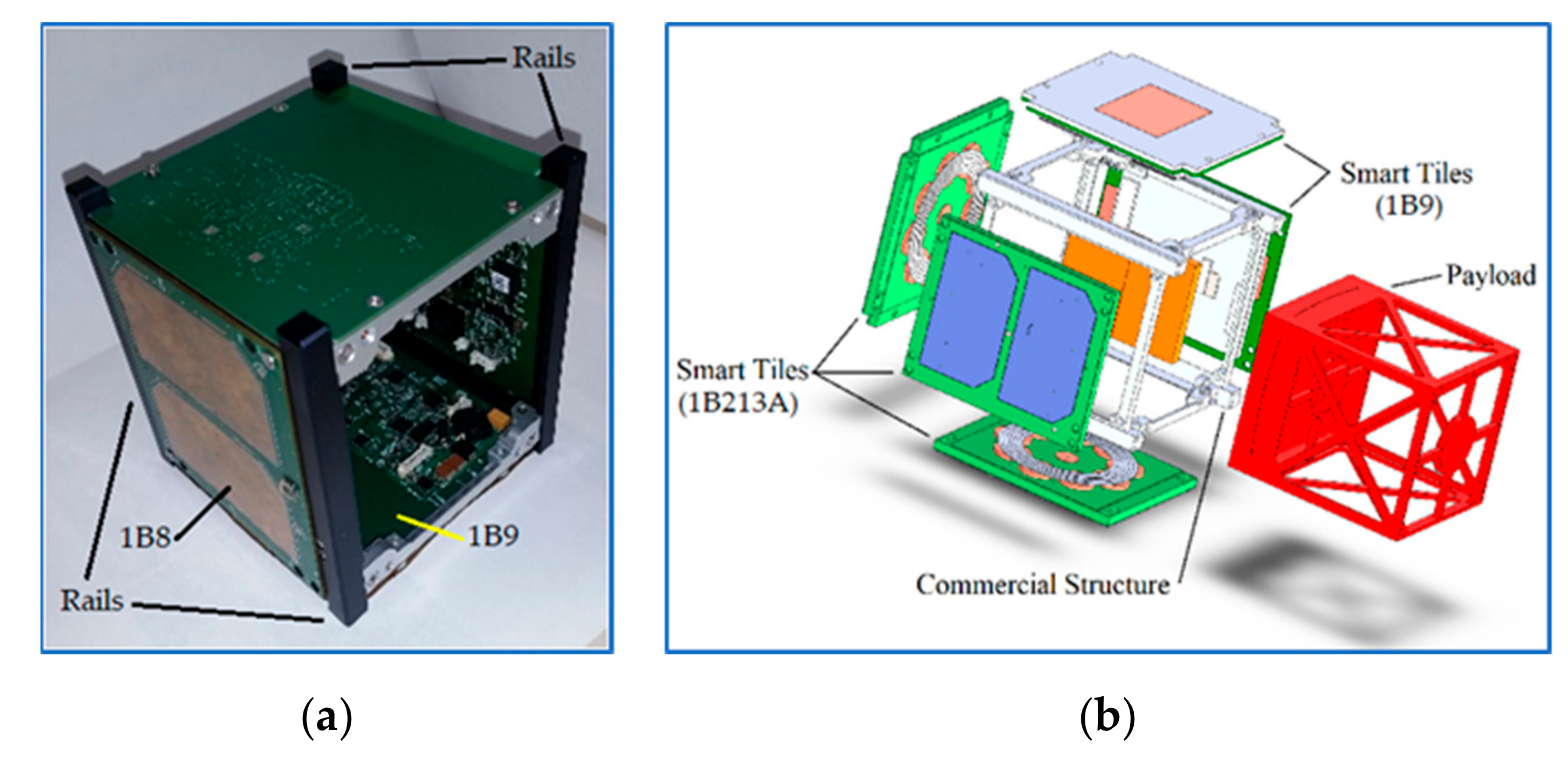
9]. Its goal is to design, produce, and test a set of “smart tiles” (Table 1) that must be mounted on the six faces of the above-mentioned commercial frame (Figure 1a). The main requirement for the tiles is their modularity. As a result, a tile accommodates mainly one bus subsystem components (Figure 1b). The modularity allows to reduce design, assembly and testing time and costs. A further reduction of costs is obtained with the use of Commercial-Off-the-Shelf (COTS) components. Clearly, an adequate level of redundancy must be considered.
Existing smart tiles include the telecommunication tile, with Tracking, Telemetry, and Command (TT&C) subsystem components, the reaction wheel tile, with Attitude and Orbit Control System (AOCS) components and the power management tile. The aim of the present design is to improve the previous 1B8 power management tile. In that case, the primary structure function was given by Printed Circuit Boards (PCBs), which are not made with structural materials. Moreover, no energy storing function was implemented.
Besides space applications, energy storing composite structural components are studied in the automotive [10], aeronautical [11], and marine [12] sectors. Vehicle mass saving in this case is more useful than internal volume saving, with respect to the CubeSat case [13]. It has been shown that energy storing composites can significantly increase the range of aircrafts, as shown in [11], for piloted electric aircraft. Energy storing composites can also improve the performances of uninhabited, long-endurance aircrafts as High-Altitude Long-Endurance (HALE) vehicles exploiting solar energy or fuel cells [14,15].

2. Materials and Methods

The functionalization of the smart tiles must take into account a strong constraint, imposed by CubeSat deployment procedure. CubeSats are usually accommodated inside the launch vehicle in standard deployers, for example the Poly-Picosatellite Orbital Deployer (P-POD) for 1U-3U form factors [2]. The P-POD is an anodized aluminum prismatic box. A spring in the deployer pushes CubeSats into space, that are guided by their rails (the vertical rods shown in Figure 1a), in contact with rails on the deployer. For this reason, no component is allowed to protrude more than 6.5 mm normal to the plane of the rails (CubeSat mechanical requirements 3.2.3 and 3.2.3.1 [2]).
The functionalization of the primary structure has begun with the design of the reaction wheel tile prototype. Reaction wheels are attitude actuators that usually occupy CubeSats internal volume. The project consisted in merging the reaction wheel and the relative mechanisms and electronic components, the solar cells with related circuitry and the primary structure. The structure was still made with PCBs, made in epoxy resin and glass fibers. This material is usually addressed as FR-4, where FR stands for Flame Retardant.
The next step is represented by the design of an energy storing smart tile prototype, with the employment of composite materials. This will free internal volume, available to the payload, and will allow spacecraft bus mass saving.

2.1. Power Storage Composite Structures

There is a wide variety of integrated energy storage systems that can be conveniently described in terms of their degree of integration [11]. Traditional energy storing subsystems with no structural integration have zero degree of integration. An example of low degree of integration assembly is the embedded battery, where existing energy storing components are included in structural elements. Although the assembly has both functions, there is functional separation at the components level. At the other extreme, examples of high degree of integration assemblies are genuine structural batteries, whose components have the structural and the electrical function at the same time. One example of structural battery has been recently developed [10]. It consists of a unidirectional carbon fiber lamina where, in addition to the usual structural functions of the constituents, the fibers act as battery electrodes and the matrix acts as the battery electrolyte. As a result, the lamina can store electrical energy. Embedded battery systems come in a variety of configurations, the most usual ones are the laminate structure [16], the sandwich structure [12,17], and the stiffener structure [12]. The laminate structure consists of a classical composite material laminate with a set of batteries accommodated in the inner layers. The batteries are mechanically connected with the laminae thanks to a resin rich region that usually has an irregular shape. The sandwich structure houses the batteries in cavities of the core material, which usually has inferior mechanical properties with respect to the skins material. Finally, batteries can be placed in the inner regions of stiffeners.
Although high degree of integration batteries are promising and allow for greater mass and volume savings, to comply with the AraMiS project design philosophy, a low degree of integration has been chosen. Indeed, COTS components are relatively cheap and can easily be assembled and tested.

2.2. Power Management Tile Architecture

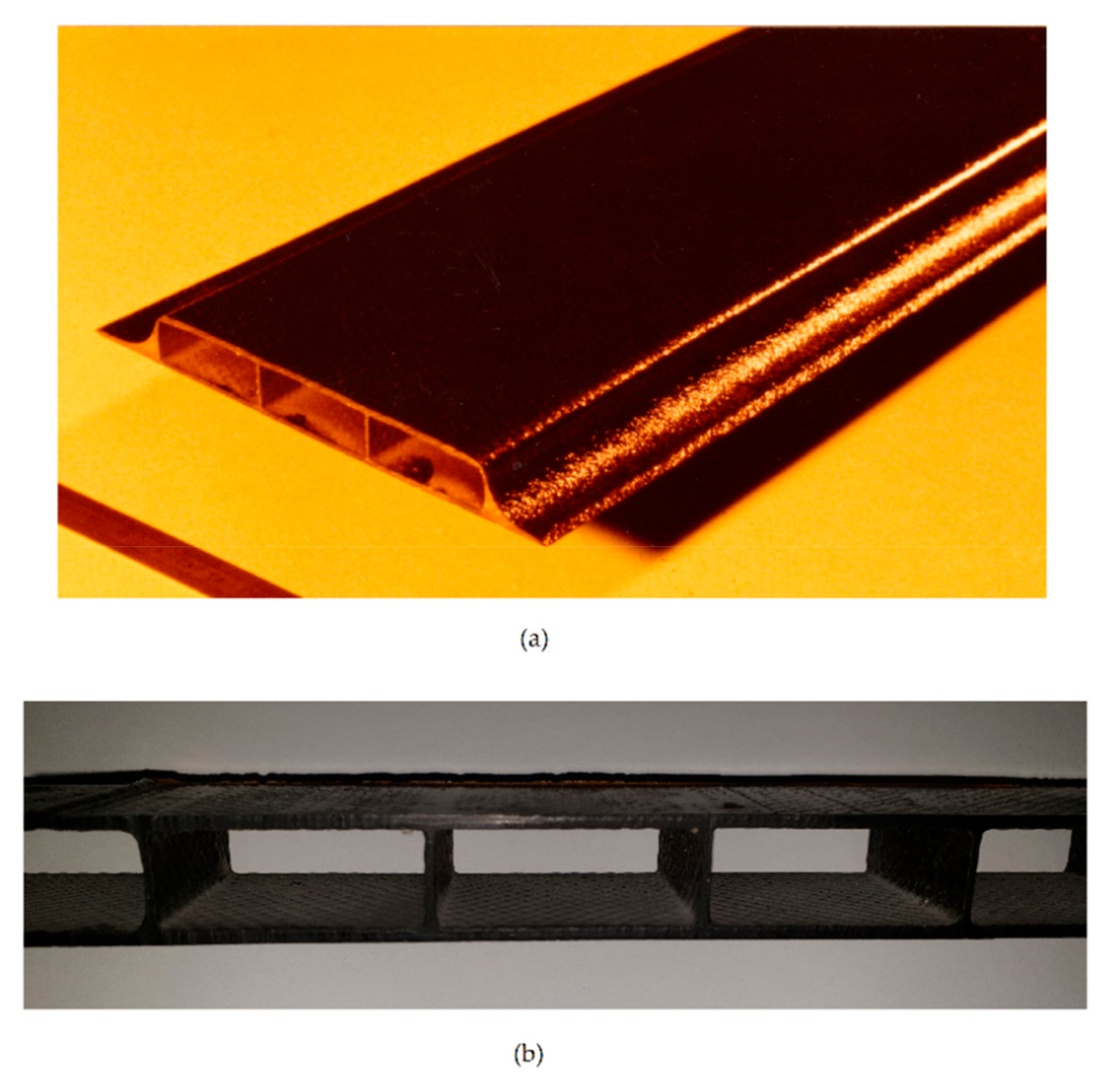
For the present design, an innovative configuration was chosen. It is a cellular configuration previously conceived for sailplanes wing boxes, in particular for the upper and lower skins [18] (Figure 2b). An evolution of this concept can as well be developed for other applications, as beam-like structures (Figure 2a) or innovative multifunctional structures (
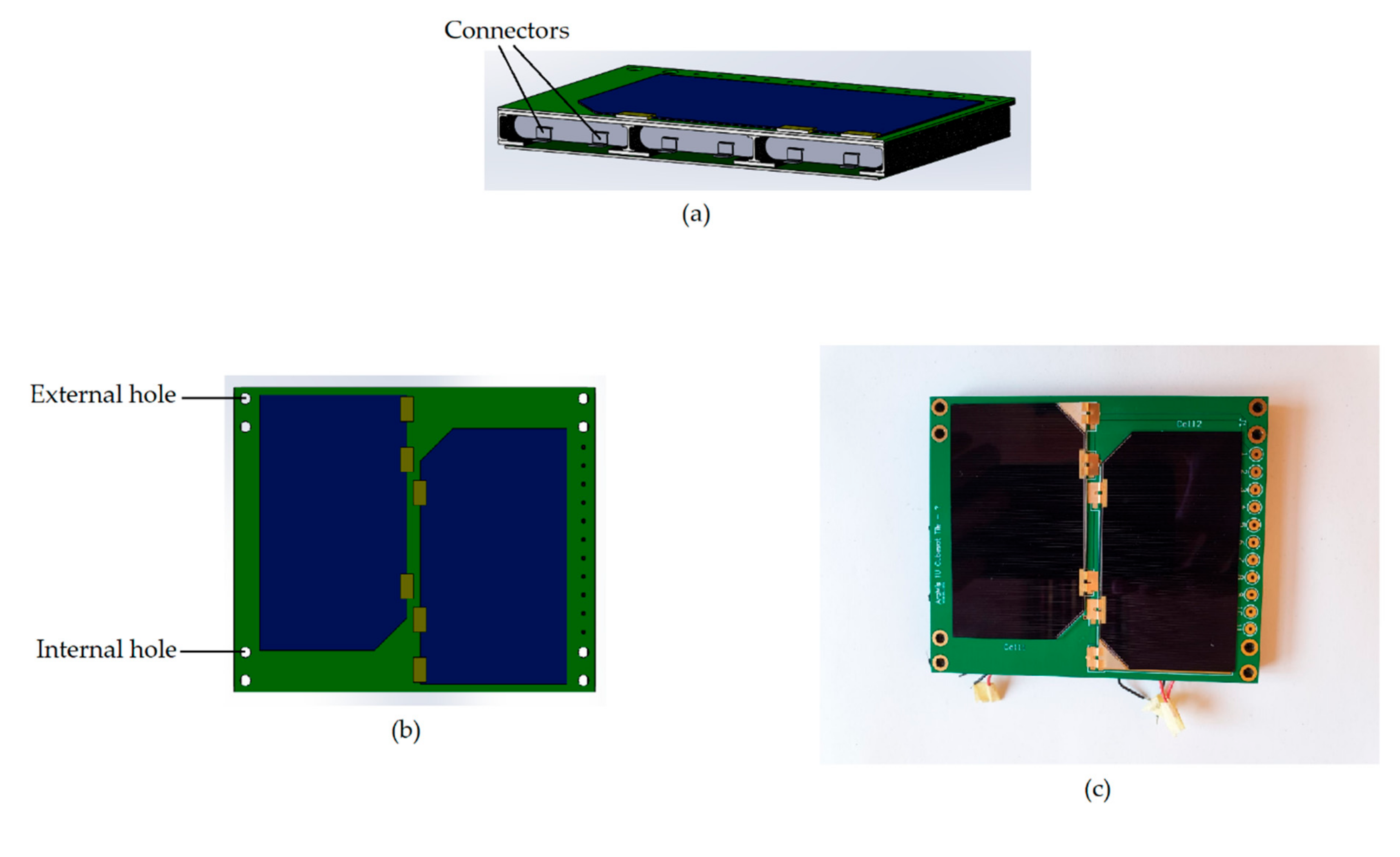
Figure 3). A CAD section and top view of the smart tile are shown in 
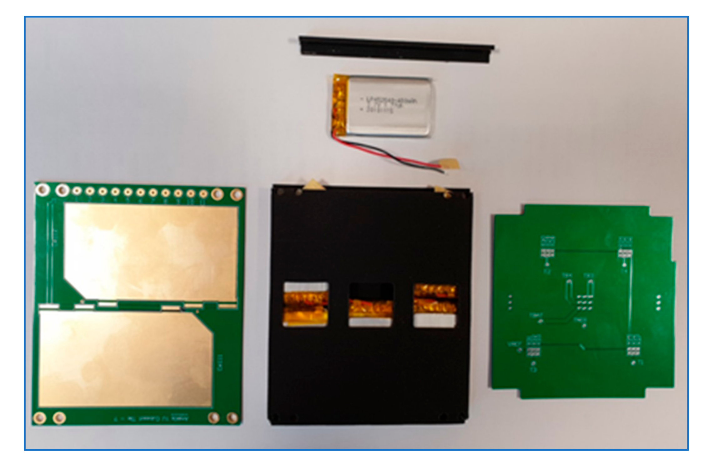
Figure 3a,b, respectively. The experimental model top view is shown in Figure 3c.
The cellular configuration has some advantages with respect to the classical configurations in [12] and [16]. It is more rigid of the solid laminate structure [16], thanks to the distance from the neutral axis of the CFRP panels. Moreover, the laminate structure had holes to house the batteries that are not necessary in the cellular structure. The cellular configuration has a major shear and bending stiffness than the sandwich structure [12], thanks to the stiffeners. In addition, CFRP cells obtained with the upper and lower panels and the stiffeners provide protection and containment for the batteries.

2.2.1. Tile Mechanical and Electrical Configuration

The upper and lower structural panels are composite laminates and hold the PCBs for the solar cells (upper panel in Figure 3a) and the electrical subsystem circuitry (lower panel in Figure 3a). The batteries are placed between the two panels, with four CFRP stiffeners among them.
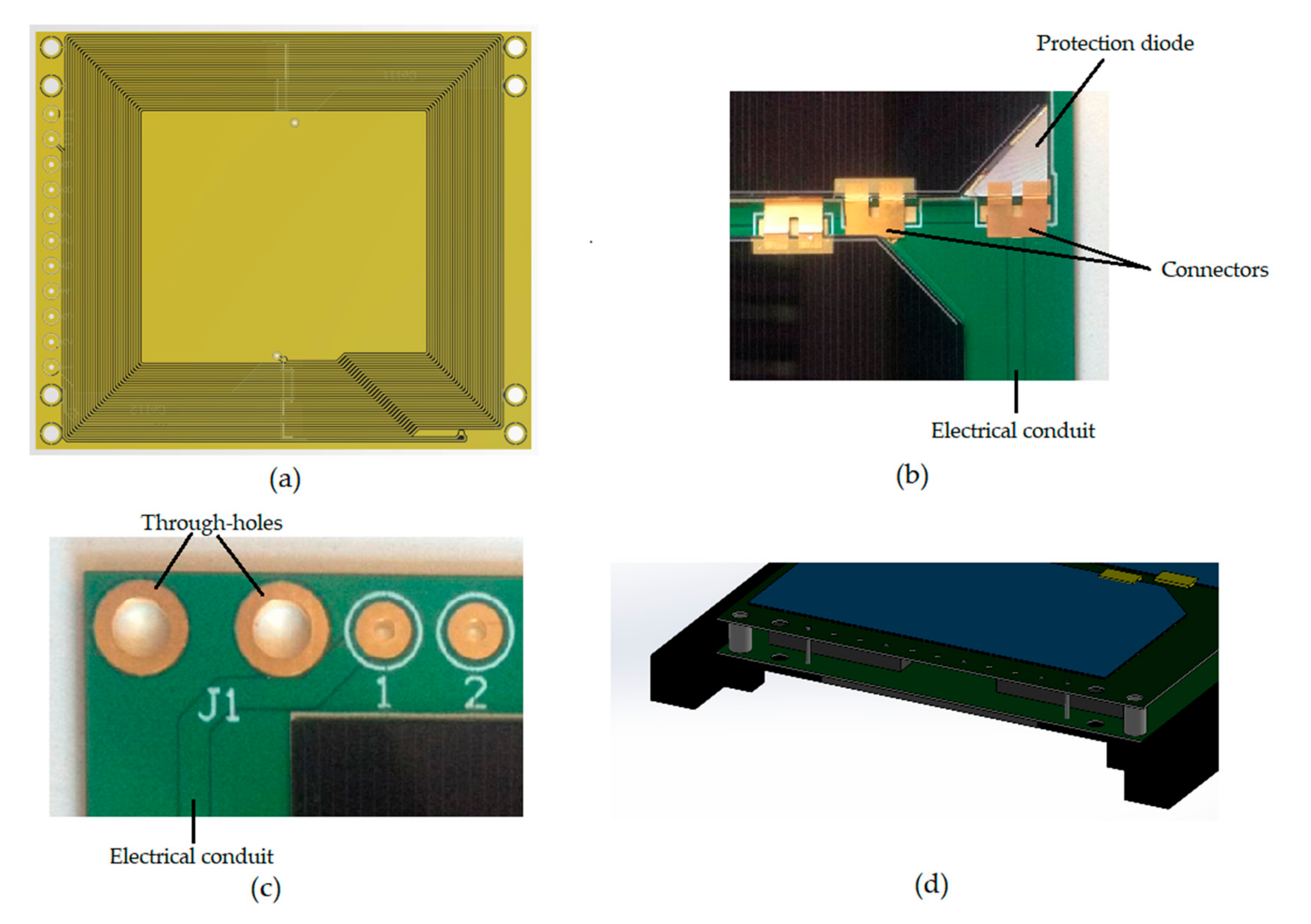
Some electronic details are shown in Figure 4: the magnetorquer (a) is buried in the solar cells PCB. The triple-junction, GaAs solar cells include a protection diode (b) and transmit electrical power through electrical conduits (c). Electrical power is carried to the inner PCB via through-holes (c, d), where it is collected in the battery array.
Mechanical connection between the batteries and the CFRP laminates is obtained with a typical silicone resin, to provide thermal protection and vibration damping for the batteries [19]. The resin adheres to all the six sides of the batteries. Electrical connection between the batteries and the inner PCB (lower PCB in Figure 3a) is obtained with holes in the CFRP lower panel to allow the passage of batteries connectors (shown in Figure 3a as thin metal strips). The mechanical connection of the tile with the commercial aluminum structure is obtained with four screws passing either through the external, cylindrical holes or through the internal, cylindrical holes (Figure 3b,c). The screws are typical aerospace inserts with a diameter of 3 millimeters. The use of external or internal holes is dictated by the choice of the cubic aluminum structure face.
With respect to classical configurations [12,16], there is additional area on the PCBs to contain two solar cells, the set of electronic components and their electrical connections to allow the proper operation of the electrical power subsystem. Moreover, it has been proven that lithium batteries, once mounted on CubeSat external panels, offer additional radiation shielding and thermal regulation [20]. However, it has been proven that radiation has negative effects on batteries performance [21].
Protection against space debris has to be studied yet. However, there is a reasonable level of redundancy due to the adoption of six batteries. Although a degradation of the electrical system performance inevitably happens in the case one battery malfunctions, the remaining five can be designed to be electrically independent.
The production of the CFRP structure can be made with standard industrial procedures and is the object of current work. Aluminum molds can be employed with a hand lay-up process of standard prepregs. The assembly then undergoes an autoclave cure cycle. PCBs and batteries are mounted after the polymerization.

2.2.2. Commercial Batteries Selection

Once the Lithium Polymer (LiPo) battery was chosen as the battery type, a preliminary investigation was performed among commercial batteries. Since AraMis is not payload-specific, the objective was to find the maximum energy storage capacity, to accommodate the widest possible range of payloads. The maximum battery thickness was set to 4.5 mm. This value has been set with the help of the CAD model (Figure 3a,b), considering the total thickness of the stack including one battery, the CFRP laminates, the PCB for the solar cells and its electronic components, once mounted on the commercial structure (Figure 1b). The maximum thickness of the stack is 6.5 mm from the plane of the rails, with an appropriate tolerance, due to CubeSat mechanical requirements discussed in Section 2. Various prismatic batteries have been considered, and the potential tile energy storage capacity was estimated. The selected battery is a Batimex LP452540 with a typical capacity of 1776 mWh (details are given in Table 2). The chosen array of six commercial batteries allows to store approximately 11 Wh in one power management tile. The total capacity is in line with actual commercial 1U-2U EPS systems [22]. It is known that batteries with similar dimensions and superior capacities exist [20,23]. However, these batteries are not COTS and have a considerable cost, thus they do not comply with AraMis project requirements. Since their shape is prismatic, it would be reasonably simple to integrate them in the present design, if they will become suitable for the project in the future. One of the objectives of present work is to demonstrate the feasibility of CubeSat subsystems with COTS components.
To increase the EPS overall capacity, the smart tiles modular approach can be exploited to obtain higher energy capacities. With two or three power management tiles mounted on the same 1U CubeSat it is possible to reach 22 or 33 Wh, respectively. Moreover, in multiples of 1U, the area of some smart tiles is increased and thus more commercial batteries can be stored in the same power management tile. For example, a 2U tile has twice the area of a 1U tile, and this allows to store up to 22 Wh with the present design. Moreover, the above-mentioned optimization can be repeated to obtain a major energy capacity per unit of tile surface.

2.3. Structural Analysis

A set of Finite Element (FE) analyses has been performed to assess the compatibility of the design with the launch mechanical environment. The Vega launch vehicle has been chosen for the analysis. The applicable launch condition [24] imposes a Limit Load (LL) of 7 g. The adopted Safety Factor (SF) value is 1.8. It is known that other authors adopted lower safety factors, e.g., Ampatzoglou et al. chose 1.25 [8]. However, with the intention of applying this technology to aeronautics also, a safety factor of 1.5 with an additional special factor of 1.2 has been chosen, to take into account the variability of material properties, as suggested for example by CS-VLA 619 and AMC VLA 619. As a result, the Ultimate Load (UL) becomes:
UL = SF × LL = 1.8 × 7 g = 12.6 g ≈ 13 g.
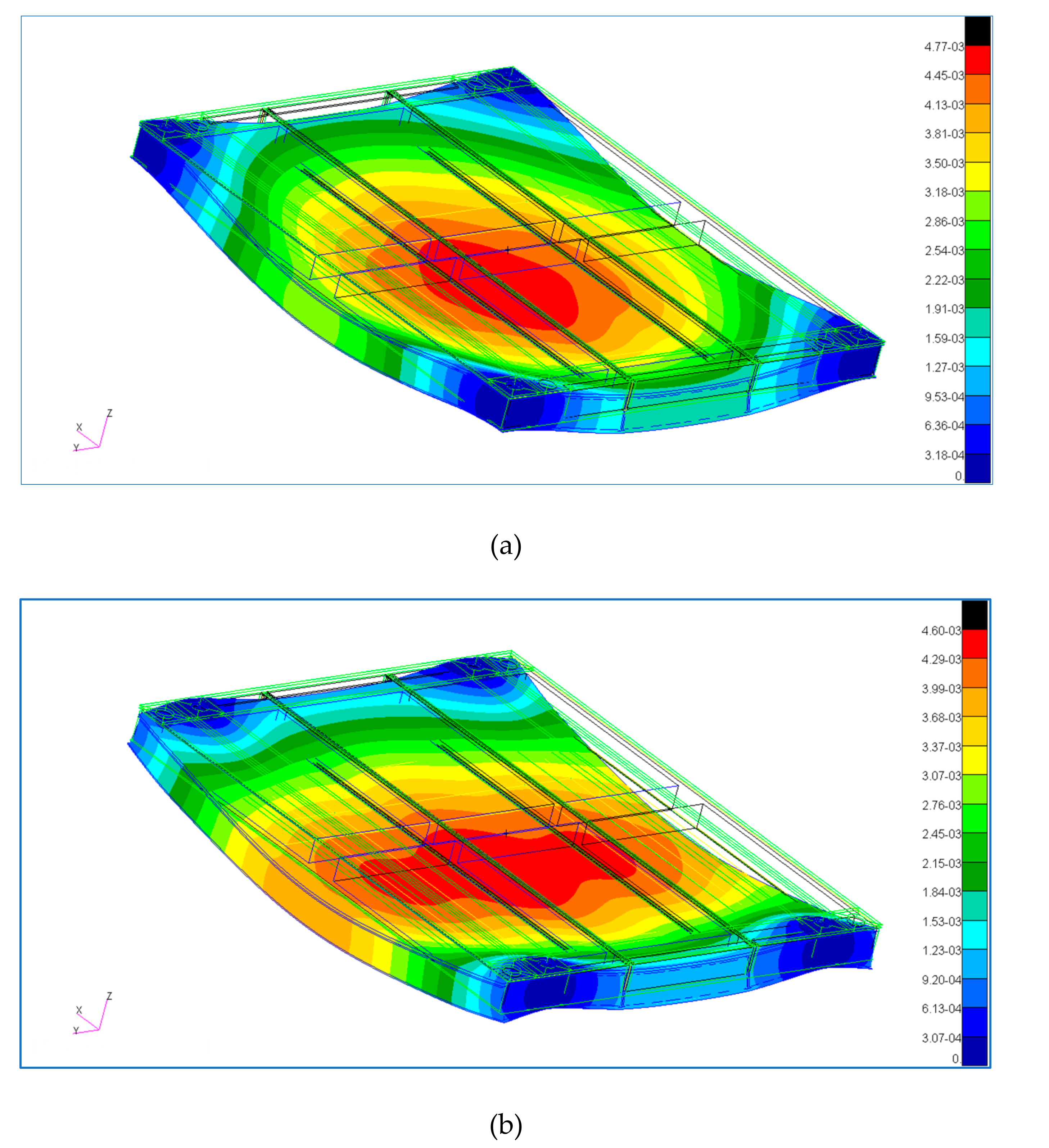
The 13 g acceleration can be applied in any direction, due to the arbitrary position of the tile on the aluminum frame and to the arbitrary orientation of the CubeSat inside the deployer. The worst case condition has been found to happen with acceleration orthogonal to the tile plane and will be described in the results section. The power management tile is mounted on the aluminum alloy frame with screws passing either through the external holes or through the internal holes (
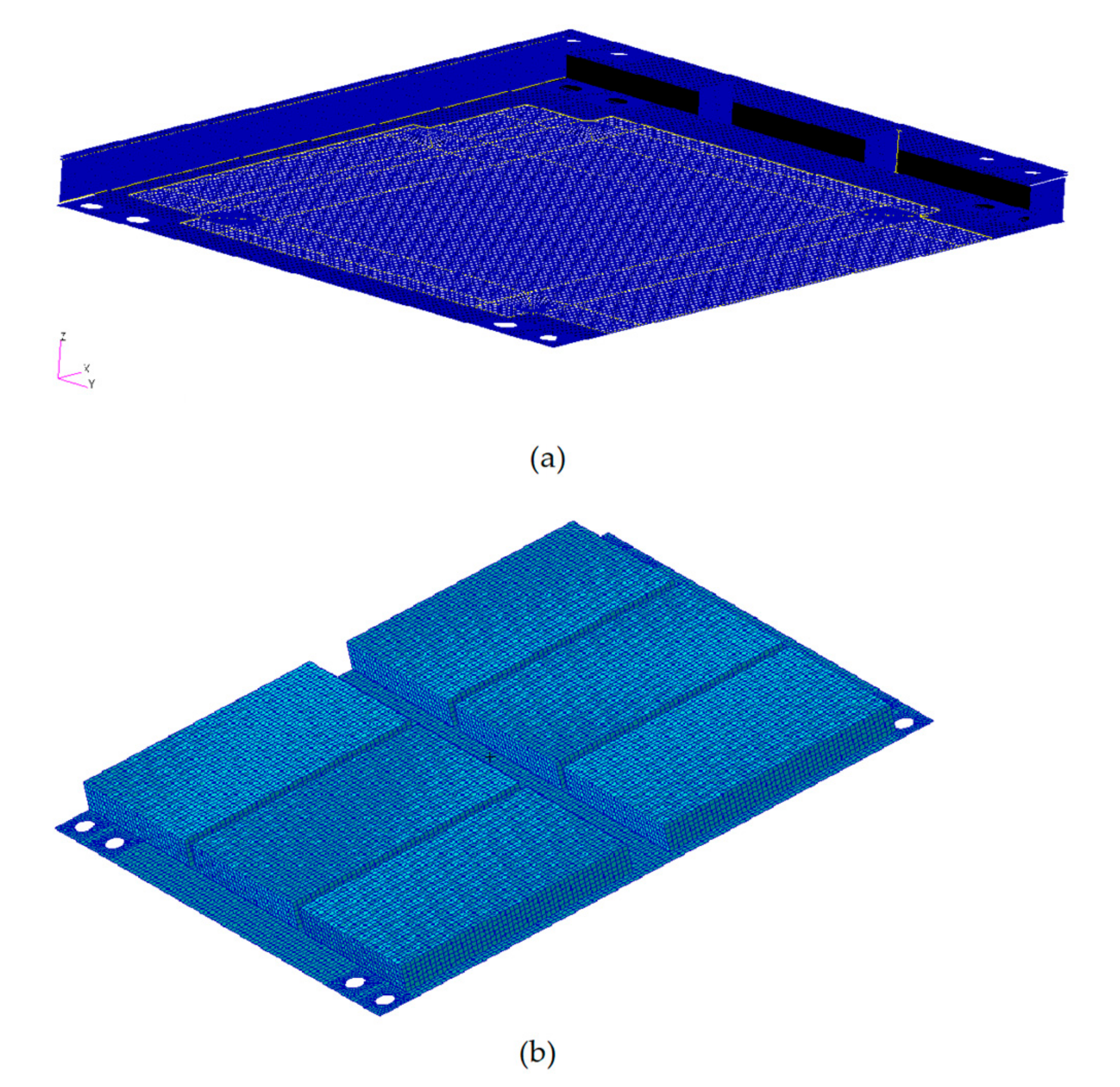
Figure 3b). Both conditions have been considered in the analysis. The degrees of freedom of nodes belonging to fastened holes have been preliminarily imposed to be zero. The FE model (Figure 5a) considers the contact of the above mentioned components, i.e., batteries, resin, CFRP laminates and PCBs. Mechanical properties of the batteries cannot easily be estimated, thus values similar to the ones found in the open literature [16] have been adopted. The mechanical properties of the materials can be found in Table 3. The CFRP panels are carbon/epoxy where a carbon fiber fabric is employed, the lamination is [±45]s.
The CFRP panels and stiffeners have been discretized with Quad4 elements with sizes ranging from 0.25 to 0.80 mm. The resin and the batteries have been discretized with Tet4 and Hex8 elements, respectively, with sizes ranging from 0.80 to 1.68 mm.
It has been observed that the mechanical layout of commercial EPSs [22,23] is rather common among commercial solutions and thus a similar configuration has been analyzed. As shown in Figure 5b, the commercial architecture is simpler than the proposed one and consists just of a PCB and six batteries, of the same type. The thickness of the PCB has been increased with respect to the proposed solution, according to commercial EPS architectures.
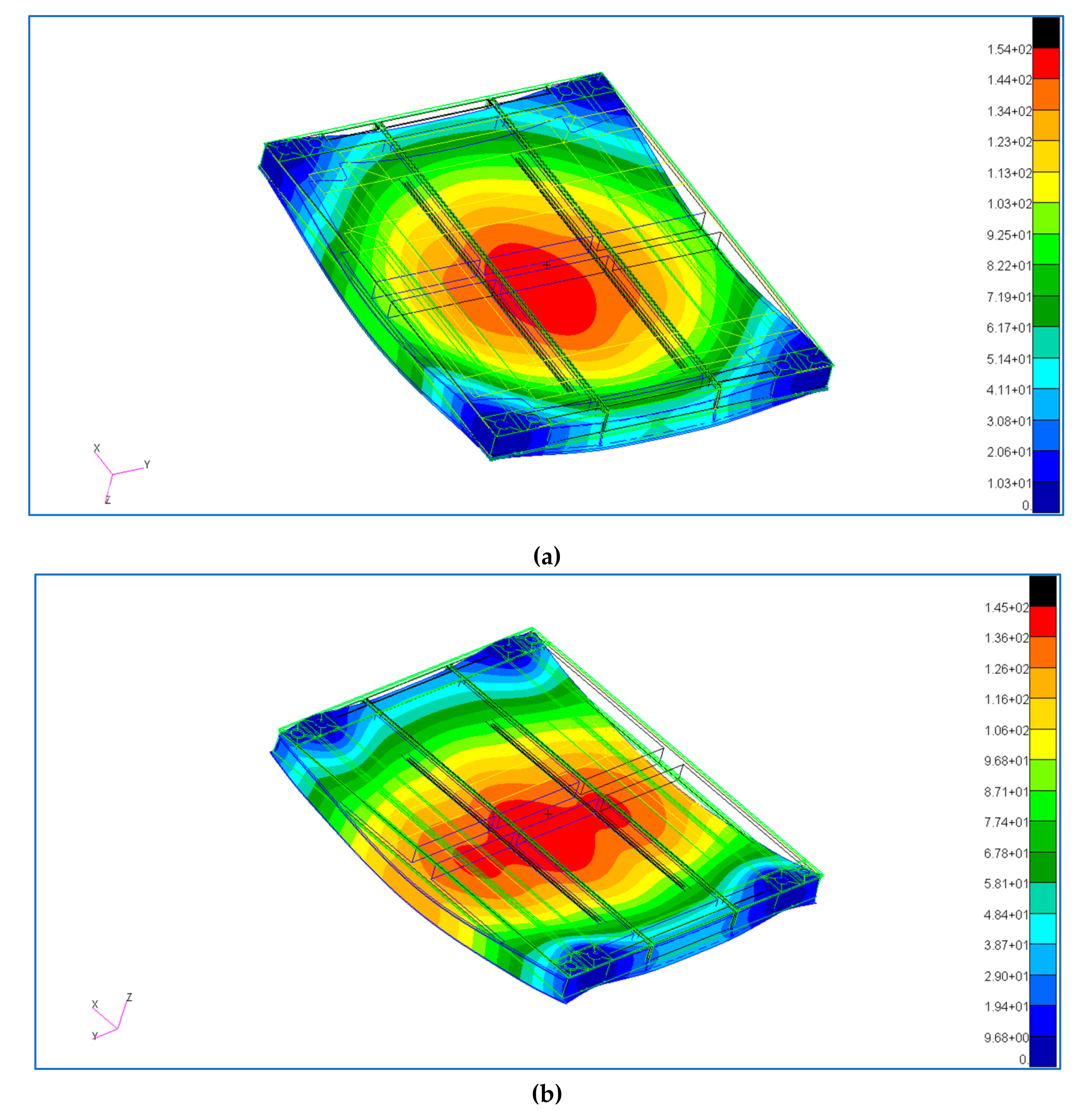
The cellular and commercial structures have been analyzed with the MSC Nastran™ software [25] and the results have been compared. A static analysis has been conducted to evaluate strains, stresses and maximum displacements. In addition, the natural frequencies and modes have been evaluated.
Simple, preliminary thermal analyses results have shown that the temperature of the batteries is below the maximum operating temperature of 60 °C, a detailed thermal analysis and experimental tests are the object of future work. At least two conditions have to be considered. The first is during the launch, when the launch vehicle ejects the payload fairings. The second is along the nominal Low Earth Orbit (LEO) orbit, and must consider as inputs the irradiation from the Sun, the terrestrial albedo and internal electrical dissipations.

3. Results and Discussion

3.1. Mass Breakdown

The mass breakdown is shown in Table 4. The mass of the filling can be improved, being almost equal to the mass of the batteries. This aspect needs to be improved and is the object of future studies. The ratio between the total tile mass and the CubeSat maximum mass is 10%. Although it is a partial result and does not involve the whole CubeSat with its payload, it is lower than the structural mass ratio of 30%, identified as unsatisfactory in the STRaND-1 project [6]. There is still margin to place the remaining subsystems components.
A comparison of total and partial masses can be done with a commercial embedded EPS [22] and a commercial aluminum alloy structure [26] (Table 5). For the latter structure, one face of the 1U cube has been considered. The PCBs weight of the proposed design is lower than the commercial embedded EPS (respectively, 7.6 g and 25.6 g). Clearly, in the proposed design there is no intended structural function of the PCBs, and thus their thickness can be reduced, while for the commercial EPS, the PCB panel is the only component able to withstand loads, and thus it has a major thickness. The structural mass for the present design (15 g) is given by the mass of CFRP elements. It is clearly lower than the structural mass of the commercial aluminum alloy panel (28 g), due to the use of composite materials.
However, the overall mass of the proposed design is greater than the mass of the commercial EPS. This is mainly due to the resin employed for mechanical and thermal insulation of the batteries, whose mass can be reduced with lighter materials. Nevertheless, in the author’s opinion, the present design has advantages with respect to its commercial counterpart. The CFRP cells provide containment and protection from the batteries for the rest of the spacecraft, and future experimental qualification tests are aimed at evaluating the protection of batteries from vibrations, excessive temperatures and thermal shocks. Furthermore with two, lighter PCBs, more area can be devoted to EPS electronic components and circuits. In addition, no internal volume is subtracted to the payload. Finally, the proposed design includes additional components with respect to the commercial design [22], i.e., solar cells, magnetorquers and additional electronic circuitry.

3.2. Finite Element Analysis

The FE static analysis (Figure 6) has revealed that the structure of the smart tile can easily survive the launch, with a maximum displacement of 4.8 μm in the worst case, i.e., with external holes blocked. The results are given in Table 6. As expected, the maximum displacement with the external holes blocked is major of the maximum displacement with internal holes blocked (respectively, 4.8 and 4.6 µm).
All the stresses and the strains are far below materials allowable limits, with external and internal holes blocked. The maximum stresses on the batteries and PCBs are in the order of tens and hundreds of kilopascals, respectively. These values are far below the materials maximum acceptable stresses.
The modal analysis (Figure 7) has provided fundamental frequencies in the order of 900 Hz for both constraint cases. Vega User’s Manual [24] prescribes that the lateral axis fundamental frequency, flat, must be equal or greater than 15 Hz:
flat ≥ 15 Hz.
And the longitudinal axis fundamental frequency, flong, must be in the range:
20 Hz < flong <45 Hz or flong > 60 Hz.
Although this is a partial result about power management tile local resonance, the above requirements are satisfied. The requirements of Equations 2 and 3 will have to be verified on the whole CubeSat.
At moment the FEM model does not consider details of electrical connections between the PCBs and the batteries. The vibration resistance of electrical connections will be proven during experimental qualification tests. Future work will establish the amount of damage accumulated in the batteries and in their electrical connections due to the launch mechanical environment.

3.3. Comparison with Commercial Architecture

The FE static and modal analysis has been repeated with the mechanical architecture of the commercial EPS (Figure 5b). Results are summarized and compared with the proposed design in Table 7. The advantages of the proposed design are evident, since its maximum displacement is minor and the fundamental frequency is major than the commercial EPS.

3.4. Comparison with Similar Studies on Embedded Batteries Structures

Besides the structural results comparison with the commercial EPS for CubeSats (Section 3.3), wider comparisons can be made with similar systems for space [20,22,23], automotive [17], and marine [12] environments.
Regarding the CubeSat EPS systems [20,22,23], it is evident that the energy capacity is higher, for some models, than the capacity of the EPS under discussion (11 Wh for the present case, against 22 Wh for [20,23]). However, in addition to the batteries, the proposed design includes solar cells, mounted on the outer PCB, additional electronic circuitry, mounted on the inner PCB, and some versions of the tile include magnetic torquers (Table 1) within the PCBs, in order to provide, together with the other tiles, a spacecraft bus as complete as possible and not only the power storage function. These components were not included in the other battery systems [20,22,23]. Moreover, the present solution is designed to be mounted on the aluminum frame of the CubeSat, to leave internal volume available for the payload, while the other battery systems [20,22,23] are accommodated inside the CubeSat.
Solutions presented in [12,17] have a different structural configuration, i.e., solid beams [12] and sandwich beams [12,17], so a comparison of the structural performances would not be useful. In any case, for both systems the functional integration of the electrical energy storage did not degrade the structural performance below acceptable limits. On the contrary, the bending performances were only marginally affected by the inclusion of the batteries. The present study confirms that, if the system is properly designed, acceptable bending properties can be obtained (Table 6). Although it has been shown that resonance frequencies are affected by the batteries [16], their introduction did not lower the fundamental frequency below acceptable limits (Section 3.2), thanks to the adoption of CFRP.

3.5. Mockup

The geometric compliance of the proposed design has been tested with the production of a mockup of the tile (Figure 8). The CFRP laminates have been 3D printed and the PCB boards have been produced.
The dimensional congruence of the CFRP structure has been verified by inserting the chosen batteries in their slots and by stacking the CFRP structure and the PCBs in the correct position. A final check was made to assure the compliance of the assembly with the commercial aluminum structure.

4. Conclusions

The results given by the illustrated design method are encouraging. Unlike commercial EPSs [20,22,23], the presented system is mounted on the CubeSat aluminum frame, leaving the internal cubic volume for the payload. The mass of the system is major than equivalent actual commercial EPSs [22], although a way to reduce it has already been foreseen, as described in Section 3.1. Moreover, the presented system includes additional components with respect to commercial EPSs [20,22,23], i.e., magnetic torquers, solar cells and additional circuitry. The FE analysis showed that the structure of the embedded battery can resist to the launch phase maximum acceleration, aboard the Vega launch vehicle. The fundamental resonance frequencies are far from the forbidden intervals. The study of the mockup and the production of the PCBs suggests that the tile is technologically feasible and that it is compliant with the low cost requirement of the AraMiS project.
In addition, the structural analysis hints that this design can be further improved, for example with cut-outs in the carbon fiber laminates. Thus, structural mass would be further reduced, retaining an adequate structural response.
The results seem to indicate that the integration of the spacecraft bus functions in the primary structure can be feasible for nanosatellites. The structure can globally withstand the launch environment, and future work will investigate local effects, e.g., the electrical connections of the batteries. The adoption of composite materials led to a functionally integrated spacecraft bus. Integration of commercial batteries increased the volume available for the payload at a reasonable cost. Volume availability for the payload, as already shown [13], has the priority on mass saving. The availability of mass and volume for the spacecraft payload will be more and more important in the future, with the increasing complexity and the ambitious objectives of incoming space missions.

Author Contributions

Conceptualization, G.C., E.C., L.M.R., and G.R.; formal analysis, G.C. and E.C.; investigation, G.C., E.C., L.M.R., and G.R.; writing—original draft preparation, G.C.; writing—review and editing, G.C., E.C., L.M.R., and G.R.; supervision, G.C., E.C., L.M.R., and G.R. All authors have read and agreed to the published version of the manuscript.

Funding

This research received no external funding.

Conflicts of Interest

The authors declare no conflict of interest.

References

  1. Heidt, H.; Puig-Suari, J.; Moore, A.; Nakasuka, S.; Twiggs, R. CubeSat: A new Generation of Picosatellite for Education and Industry Low-Cost Space Experimentation. In Proceedings of the 14th Annual/USU conference on small satellites, Logan, UT, USA, 21–24 August 2000. [Google Scholar]
  2. CubeSat Design Specification. Available online: https://static1.squarespace.com/static/5418c831e4b0fa4ecac1bacd/t/56e9b62337013b6c063a655a/1458157095454/cds_rev13_final2.pdf (accessed on 22 November 2019).
  3. Poghosyan, A.; Golkar, A. CubeSat evolution: Analyzing CubeSat capabilities for conducting science missions. Progr. Aerosp. Sci. 2017, 88, 59–83. [Google Scholar] [CrossRef]
  4. CubeSats Database. Available online: https://sites.google.com/a/slu.edu/swartwout/home/cubesat-database/census (accessed on 22 November 2019).
  5. Janson, S.W.; Welle, R.P.; Rose, T.S.; Rowen, D.W.; Hinkley, B.S.; La Lumondiere, S.D.; Maul, G.A.; Werner, N.I. The NASA Optical Communication and Sensors Demonstration Program: Preflight Update. In Proceedings of the 29th Annual AIAA/USU Conference on Small Satellites, Logan, UT, USA, 13 August 2015. [Google Scholar]
  6. Kenyon, S.; Bridges, C.P.; Liddle, D.; Dyer, R.; Parsons, J.; Feltham, D.; Taylor, R.; Mellor, D.; Schofield, A.; Linehan, R. STRaND-1: Use of a $500 Smartphone as the Central Avionics of a Nanosatellite. In Proceedings of the 62nd international astronautical congress, Cape Town, South Africa, 3–7 October 2011. [Google Scholar]
  7. Pranajaya, F.M.; Zee, R.E. Generic Nanosatellite Bus for Responsive Mission. In Proceedings of the 5th responsive space conference, Los Angeles, CA, USA, 23–26 April 2007; AIAA-RS5 2007-5005. [Google Scholar]
  8. Ampatzoglou, A.; Baltopoulos, A.; Kotzakolios, A.; Kostopoulos, V. Qualification of Composite Structure for Cubesat Picosatellites as a Demonstration for Small Satellite Elements. IJASAR 2014, 1, 1–10. [Google Scholar]
  9. Speretta, S.; Reyneri, L.M.; Sanso´e, C.; Tranchero, M.; Passerone, C.; Corso, D.D. Modular Architecture for Satellites. In Proceedings of the 58th International Astronautical Congress, Hyderabad, India, 24–28 September 2007. [Google Scholar]
  10. Johannisson, W.; Ihrner, N.; Zenkert, D.; Johansson, M.; Carlstedt, D.; Asp, L.E.; Sieland, F. Multifunctional performance of a carbon fiber UD lamina electrode for structural batteries. Compos. Sci. Technol. 2018, 168, 81–87. [Google Scholar] [CrossRef]
  11. Adam, T.J.; Liao, G.; Petersen, J.; Geier, S.; Finke, B.; Wierach, P.; Kwade, A.; Wiedemann, M. Multifunctional Composites for Future Energy Storage in Aerospace Structures. Energies 2018, 11, 335. [Google Scholar] [CrossRef] [Green Version]
  12. Thomas, J.P.; Qidway, M.A.; Pogue III, W.R.; Rohatgi, A. Multifunctional structure-battery composites for marine systems. J. Compos. Mater. 2013, 47, 5–26. [Google Scholar] [CrossRef]
  13. Swartwout, M. The First One Hundred CubeSats: A Statistical Look. JoSS 2013, 2, 213–233. [Google Scholar]
  14. Romeo, G.; Borello, F.; Correa, G.; Cestino, E. ENFICA-FC: Design of transport aircraft powered by fuel cell & flight test of zero emission 2-seater aircraft powered by fuel cells fueled by hydrogen. Int. J. Hydrogen Energ. 2013, 38, 469–479. [Google Scholar]
  15. Romeo, G.; Frulla, G.; Cestino, E. Design of a High-Altitude Long-Endurance Solar-Powered Unmanned Air Vehicle for Multi-Payload and Operations. Proc. Inst. Mech. Eng. G 2007, 221, 199–216. [Google Scholar] [CrossRef] [Green Version]
  16. Galos, J.; Afaghi Khatibi, A.; Mouritz, A.P. Vibration and acoustic properties of composites with embedded lithium-ion polymer batteries. Compos. Struct. 2019, 220, 677–686. [Google Scholar] [CrossRef]
  17. Galos, J.; Best, A.S.; Mouritz, A.P. Multifunctional sandwich composites containing embedded lithium-ion polymer batteries under bending loads. Mater. Design 2020, 185. [Google Scholar] [CrossRef]
  18. Romeo, G. Sailplane wing box design by use of graphite/aramide/epoxy material. Tech. Soar. 1981, 2, 70–75. [Google Scholar]
  19. The Use of Silicone Adhesives in Space Applications. Available online: https://www.adhesivesmag.com/articles/85082-the-use-of-silicone-adhesives-in-space-applications (accessed on 25 November 2019).
  20. Nader, R.; Uriguen, M.; Drouet, S.; Nader Drouet, G. High Energy Density Battery Array for CubeSat Missions. In Proceedings of the 67th International Astronautical Congress, Guadalajara, Mexico, 26–30 September 2016 ; Curran Associates, Inc.: New York, NY, USA, 2017; p. 32401. [Google Scholar]
  21. Tan, C.; Lyons, D.J.; Pan, K.; Yee Leung, K.; Chiurazzi, W.C.; Canova, M.; Co, A.C.; Cao, L.R. Radiation effects on the electrode and electrolyte of a lithium-ion battery. J. Power Sources 2016, 318. [Google Scholar] [CrossRef]
  22. Crystalspace P1U “Vasik” EPS. Available online: https://www.cubesatshop.com/product/crystalspace-p1u-vasik/ (accessed on 22 November 2019).
  23. BA0x High Energy Density Battery Array. Available online: https://www.cubesatshop.com/product/ba0x-high-energy-density-battery-array/ (accessed on 26 November 2019).
  24. Vega User’s Manual Issue 4 Revision 0. Available online: http://www.arianespace.com/wp-content/uploads/2015/09/Vega-Users-Manual_Issue-04_April-2014.pdf (accessed on 22 November 2019).
  25. MSC Nastran™ Quick Reference Guide 2017. Available online: https://simcompanion.mscsoftware.com/infocenter/index?page=content&id=DOC11146& (accessed on 11 February 2020).
  26. CubeSat KitTM Pro Chassis Walls. Available online: https://www.pumpkinspace.com/store/p42/CubeSat_Kit%E2%84%A2_Pro_Chassis_Walls.html (accessed on 22 November 2019).
Figure 1. AraMiS CubeSat: (a) Prototype and (b) General architecture. Integrated bus functions include: power management (in the previous power management tile 1B8 and current work), Tracking, Telemetry and Command (TT & C, telecommunication tile 1B9), and attitude control by reaction wheels (reaction wheel tile 1B213A). Some functions like power generation are distributed over several tiles.
Aerospace 07 00017 g001
Figure 2. Aeronautical cellular structures: (a) Cellular beam and (b) Rectangular cellular panel. Panel thicknesses: top and bottom skin 2 mm, cell width 33 mm, cell height 12 mm, and side walls 1 mm.
Aerospace 07 00017 g002
Figure 3. Power management tile: (a) CAD model section. The cross-section is colored in white; (b) CAD model top view; and (c) Experimental model top view.
Aerospace 07 00017 g003
Figure 4. Power management tile electronic details: magnetorquer (a), solar cells connectors with protection diode (b), solar cells electrical conduit (c), and electrical connection with battery array (d).
Aerospace 07 00017 g004
Figure 5. FE models mesh: (a) Cellular configuration; (b) Commercial Electrical Power System (EPS) architecture.
Aerospace 07 00017 g005
Figure 6. Static deformations: (a) External holes blocked and (b) Internal holes blocked. Displacements are given in millimeters.
Aerospace 07 00017 g006
Figure 7. Fundamental modes: (a) External holes blocked; and (b) Internal holes blocked. Displacements are given in millimetres.
Aerospace 07 00017 g007
Figure 8. Mockup of the proposed design.
Aerospace 07 00017 g008
Table 1. Existing smart tiles.
NameCodeMain Subsystem/ComponentsReference
Power management tile1B8OBC (On Board Computer, simple microprocessor)
EPS (solar cells, primary converter)
AOCS (gyroscopes, magnetometers, magnetorquers)
Figure 1a, front
CFRP power management tile version 11B68_V1EPS (solar cells, secondary batteries)Section 2.2
CFRP power management tile version 21B68_V2EPS (solar cells, secondary batteries)
AOCS (magnetorquers)
Section 2.2
Telecommunication tile1B9TT&C components (frequency bands: 437 MHz and 2.4 GHz)Figure 1a, bottom, Figure 1b, top and back-right
Reaction wheel tile1B213AAOCS (reaction wheel, gyroscopes, magnetometers)
EPS (solar cells)
Figure 1b, front, bottom and back-left
Table 2. Selected battery characteristics.
ParameterValue
Nominal voltage3.7V
Typical capacity1.78Wh
Maximum length40.0mm
Maximum width25.5mm
Maximum thickness4.5mm
Typical mass10.0g
Table 3. Materials mechanical properties for the Finite Element (FE) analysis.
MaterialEνGρ
[MPa]-[MPa][g/cm3]
Battery assembly150.000.3057.692.08
Resin218.000.3083.851.27
FR430000.391079.141.20
MaterialE11E22ν12G12ρ
[MPa][MPa]-[MPa][g/cm3]
CFRP70000700000.1050001.60
Table 4. Mass breakdown for the proposed design.
ComponentMass
[g][%]
CFRP1510.95%
Batteries6043.80%
PCBs7.65.55%
Filling54.439.70%
Total137100%
Table 5. Masses comparison.
QuantityProposed CFRP DesignCommercial Embedded Battery [22]Commercial Structural Al Panel [26]
Total mass[g]1378028
PCB mass[g]7.625.6 (estimated)-
Structural mass[g]15-28
Capacity[Wh]11110
Table 6. FE static and modal analysis results.
Quantity External Holes BlockedInternal Holes Blocked
Maximum displacement[µm]4.84.6
Fundamental frequency[Hz]963956
Table 7. Comparison between proposed and commercial architectures.
Quantity Proposed Design Commercial EPS
External Holes Blocked
Maximum displacement[mm]4.8 × 10−30.27
Fundamental frequency[Hz]963133

