Trajectory Design of Perseus: A CubeSat Mission Concept to Phobos

 ,
,  ,
,
Abstract
:1. Introduction
2. Related Work
3. Science
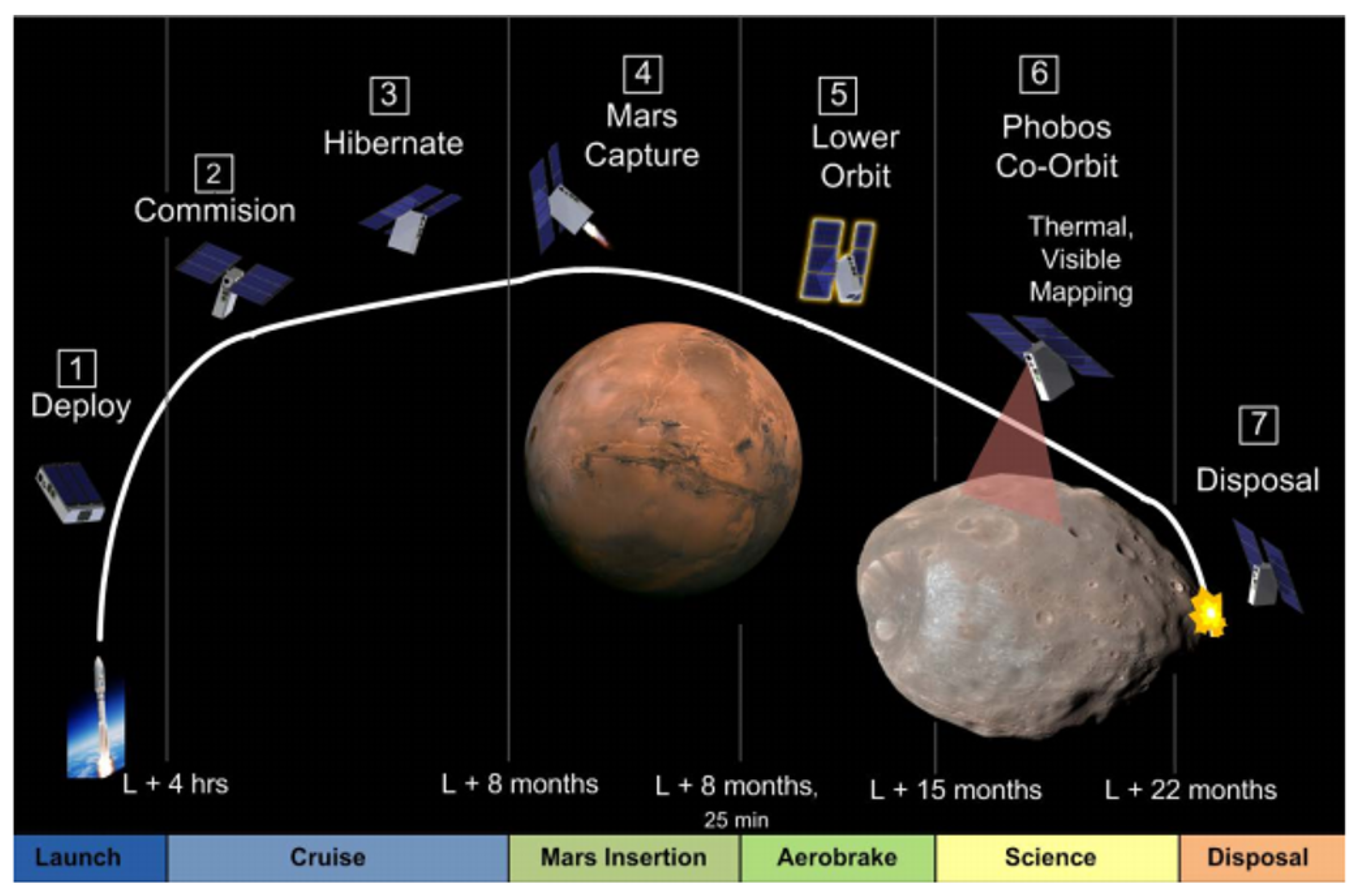
4. Concept of Operations
5. Spacecraft
5.1. Science Payload
5.2. Propulsion
5.3. Attitude Determination and Control System
5.4. Command and Data Handling
5.5. Communications
5.6. Power System
6. Trajectory Design
- Heliocentric Cruise
- Co-orbital Mission Concept
- Hyperbolic Mission Concept
6.1. Heliocentric Cruise
6.2. Co-Orbital Mission Concept
- HEO capture
- Walk-in
- Main phase
- Walk-out
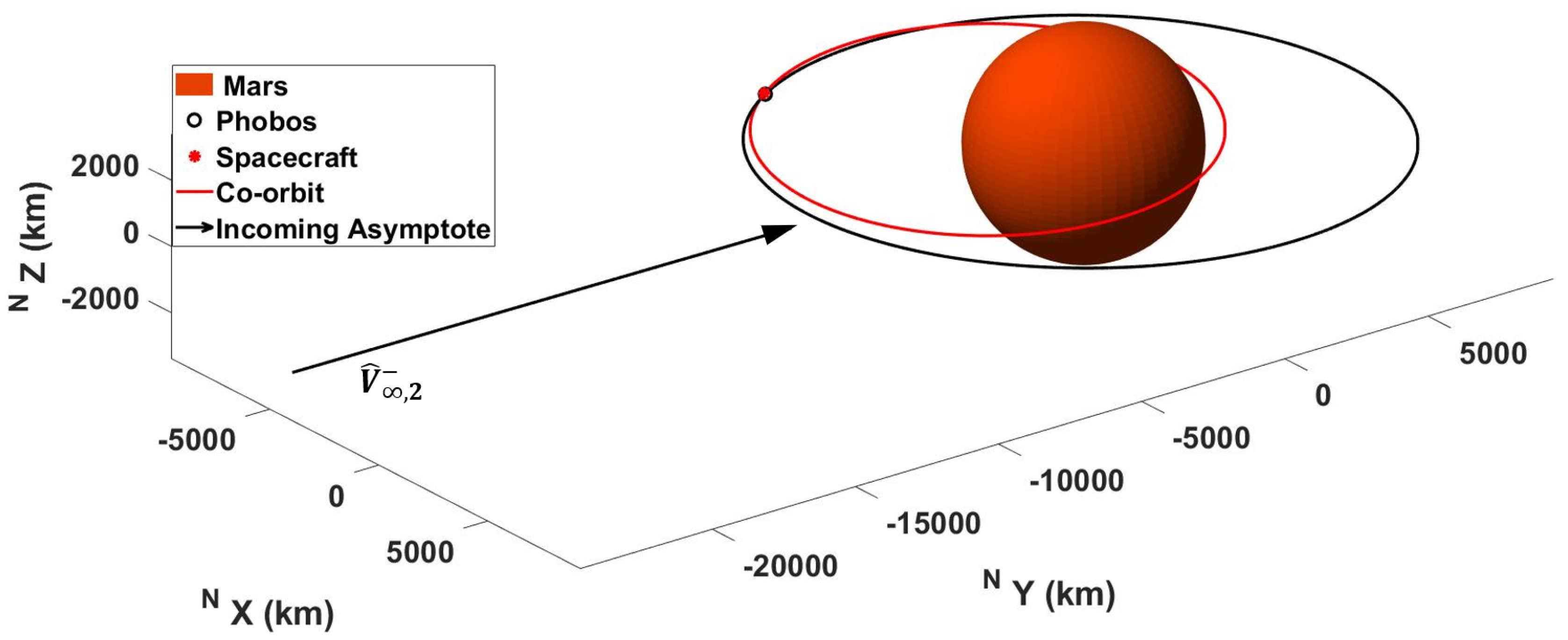
Co-Orbit Design
6.3. Hyperbolic Mission Concept
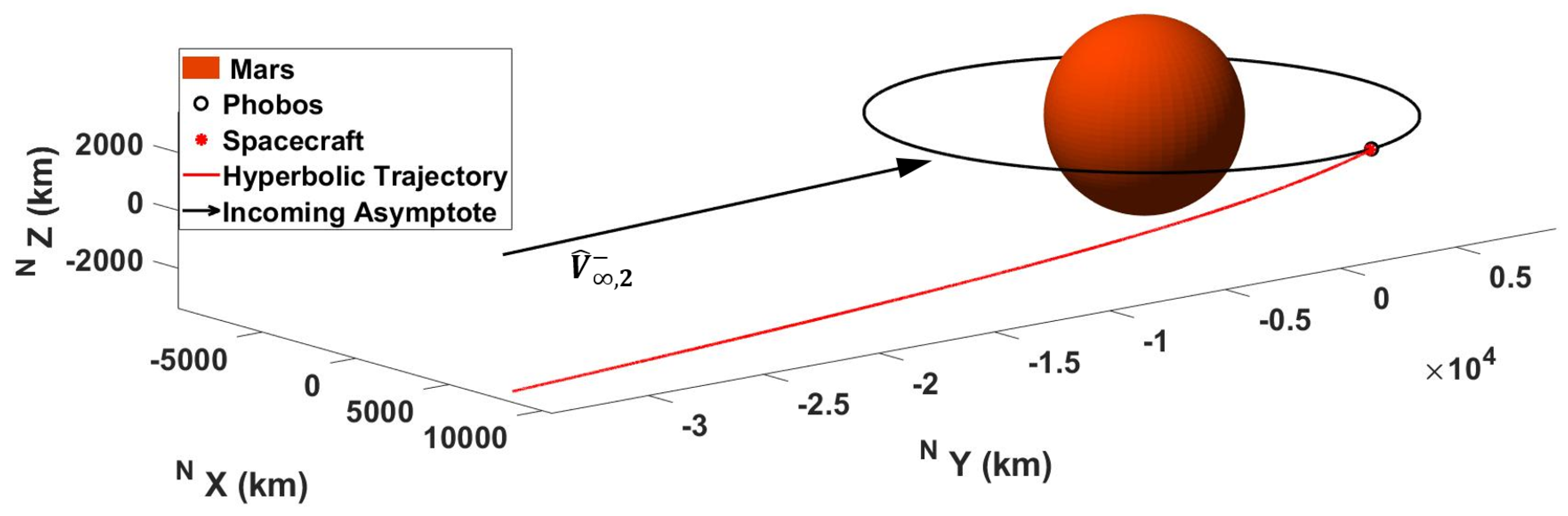
6.3.1. Hyperbolic Trajectory Construction
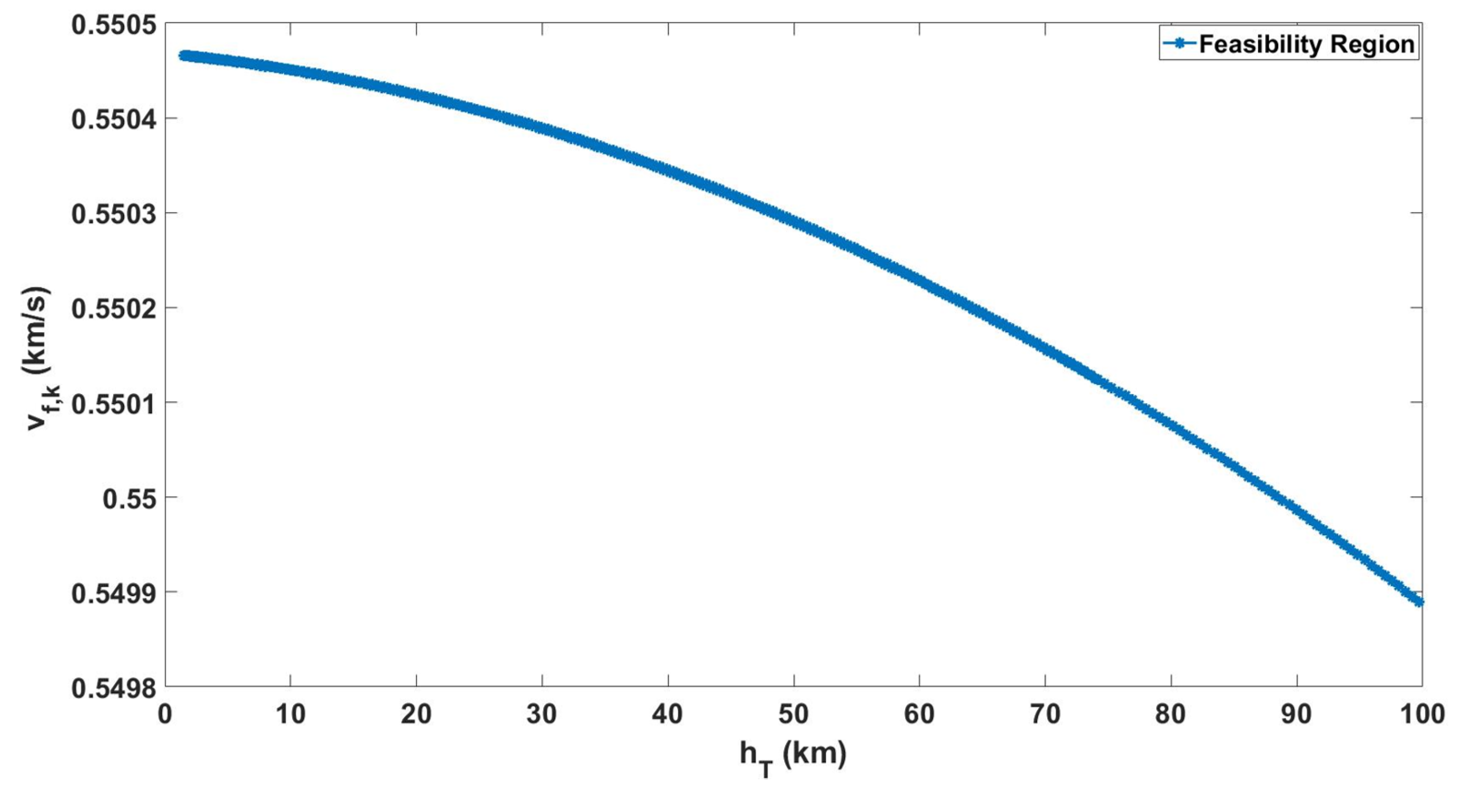
6.3.2. Hyperbolic Trajectory Design
7. Results
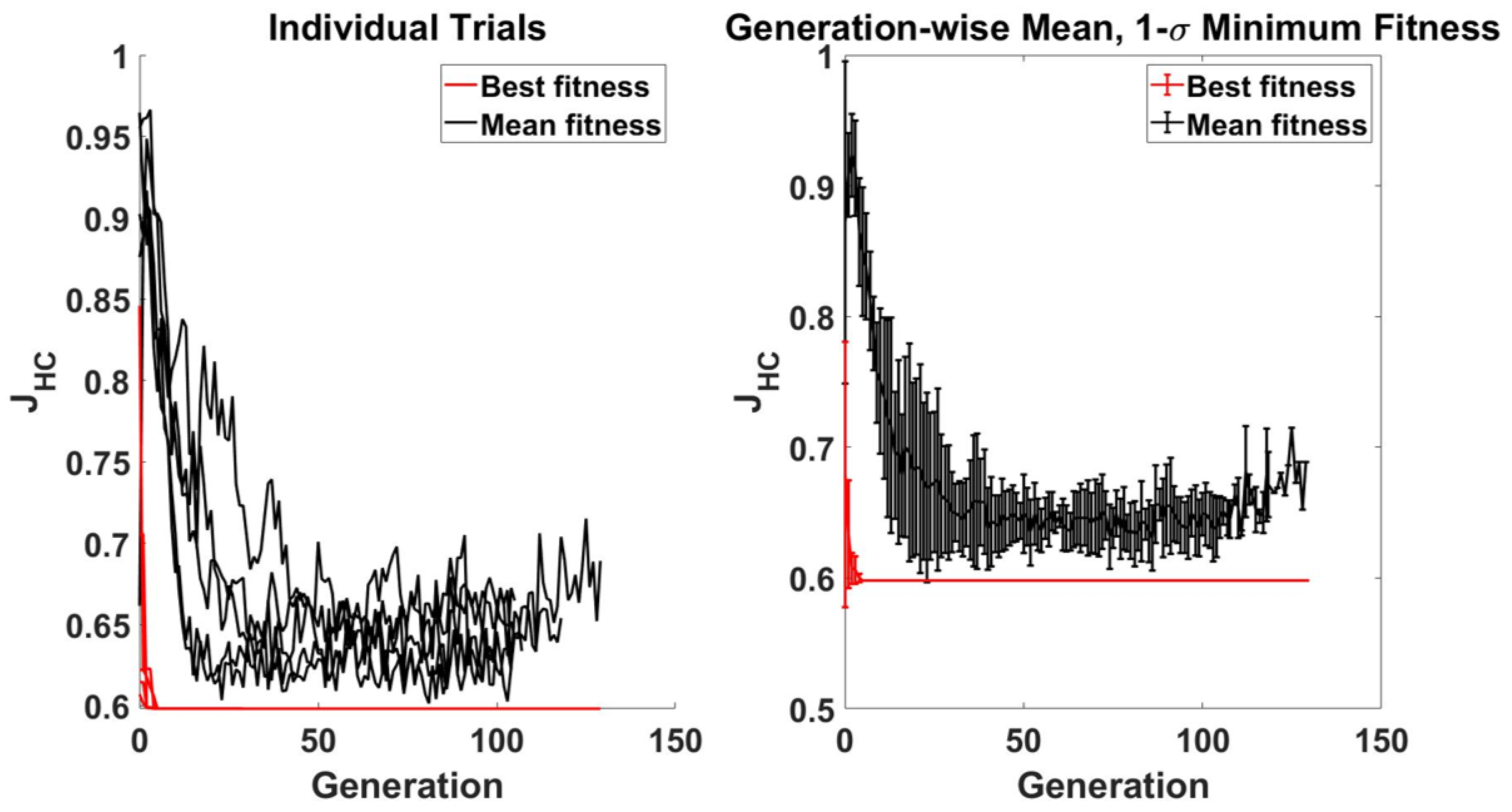
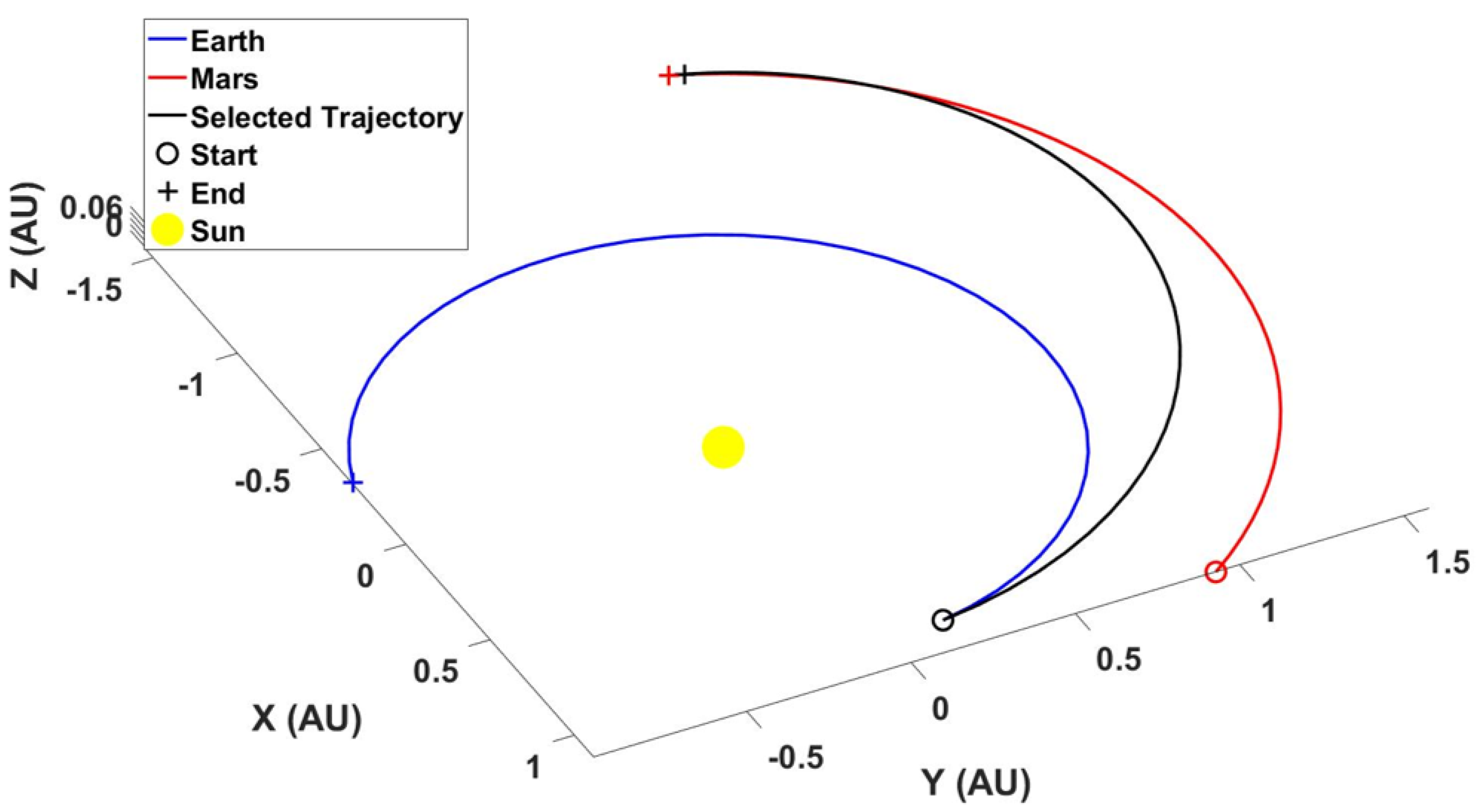
7.1. Heliocentric Cruise
7.2. Dynamical Environment
7.3. Co-Orbital Mission
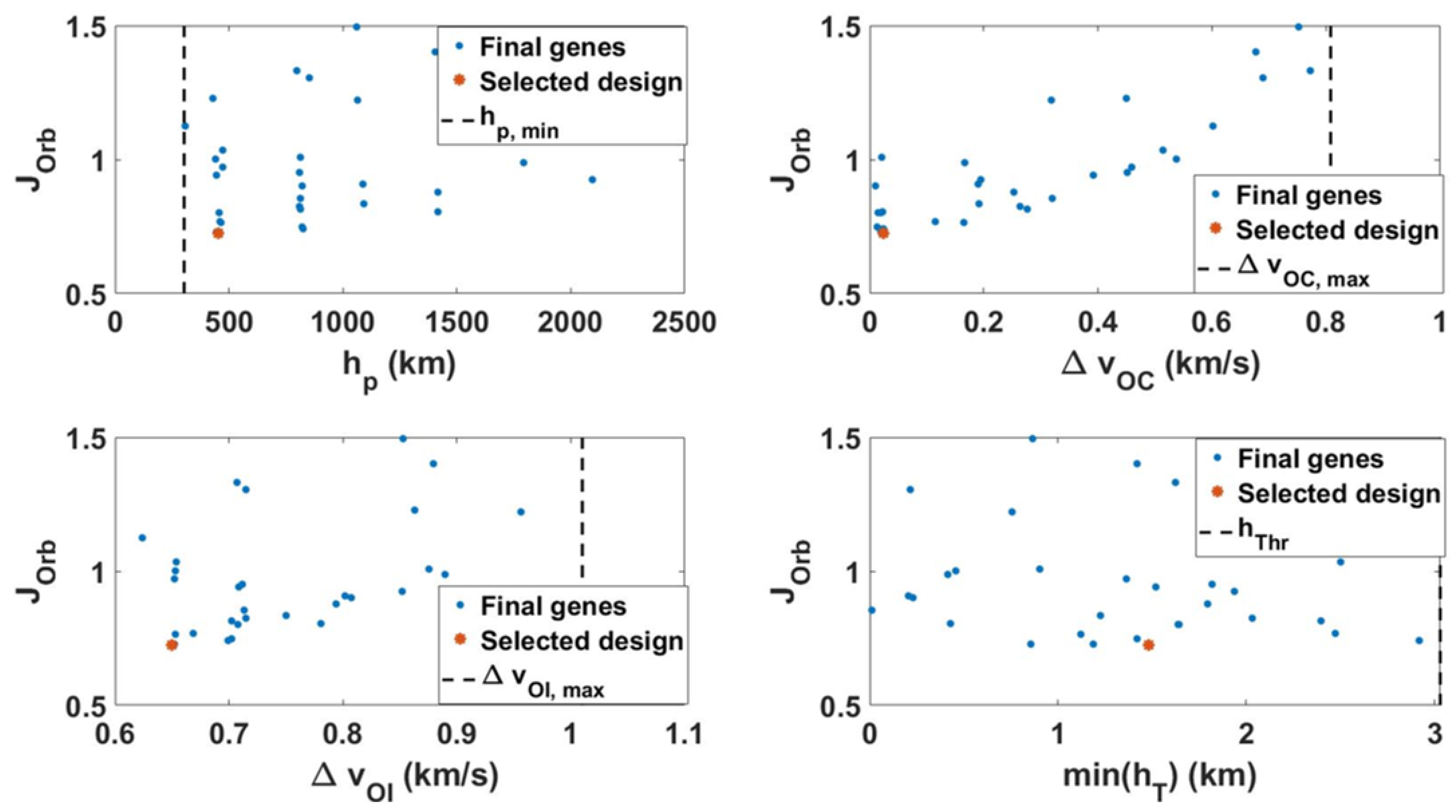
7.3.1. Orbit Insertion
7.3.2. Encounter Performance
7.4. Hyperbolic Mission
Encounter Performance
7.5. Discussion
8. Conclusions
Author Contributions
Funding
Conflicts of Interest
References
- Staehle, R.; Blaney, D.; Hemmati, H.; Jones, D.; Anderson, B.; Betts, B.; Chow, C.; Friedman, L.; Klesh, A.; Liewer, P.; et al. Interplanetary CubeSats: Opening the Solar System to a Broad Community at Lower Cost. J. Small Satell. 2013, 2, 161–186. [Google Scholar]
- Schoolcraft, J.; Klesh, A.; Werne, T. MarCO: Interplanetary Mission Development On a CubeSat Scale. In Proceedings of the AIAA SpaceOps 2016 Conference, SpaceOps Conferences, Daejeon, Korea, 16–20 May 2016; p. 2491. [Google Scholar]
- Hodges, R.; Hoppe, D.J.; Radway, M.J.; Chahat, N.E. Novel Deployable Reflectarray Antennas for CubeSat Communications. In Proceedings of the 2015 IEEE MTT-S International Microwave Symposium, Phoenix, AZ, USA, 17–22 May 2015. [Google Scholar]
- Asphaug, E. Rise and Fall of the Martian Moons. Nat. Geosci. 2016, 9, 568–569. [Google Scholar] [CrossRef]
- Ball, A.J.; Price, M.E.; Walker, R.J.; Dando, G.C.; Wells, N.S.; Zarnecki, J.C. Mars Phobos and Deimos Survey (M-PADS)—A Martian Moons Orbiter and Phobos Lander. Adv. Space Res. 2009, 43, 120–127. [Google Scholar] [CrossRef] [Green Version]
- Duxbury, T.C. Spacecraft Exploration of Phobos and Deimos. Planet. Space Sci. 2014, 102, 9–17. [Google Scholar] [CrossRef] [Green Version]
- Murchie, S.L. The Scientific Rationale for Robotic Exploration of Phobos and Deimos; Applied Physics Laboratory, Johns Hopkins University: Laurel, MD, USA, 2009. [Google Scholar]
- Nayak, M.; Asphaug, E. Sesquinary catenae on the Martian satellite Phobos from reaccretion of escaping ejecta. Nat. Commun. 2016, 7, 12591. [Google Scholar] [CrossRef]
- National Research Council. Vision and Voyages for Planetary Science in the Decade 2013–2022; The National Academies Press: Washington, DC, USA, 2011. [Google Scholar]
- National Aeronautics and Space Administration. NASA’s Journey to Mars; NASA Head Quarters: Washington, DC, USA, 2015.
- Waldron, R.D. A Survey of Resource Utilization Processes for Mars and Its Moons. In Proceedings of the 14th SSI/Princeton Conference on Space Manufacturing, Space Studies Institute, Princeton, NJ, USA, 6–9 May 1999; pp. 53–63. [Google Scholar]
- Muscatello, A.C.; Mueller, R.; Sanders, G.B.; Larson, W.E. Phobos and Deimos Sample Collection Missions for Science and ISRU. In Proceedings of the Lunar and Planetary Science Conference (LPSC), Houston, TX, USA, 19–23 March 2012; p. 4296. [Google Scholar]
- Miyamoto, H. Japanese Mission of the Two Moons of Mars with Sample Return from Phobos; Mars Exploration Program Analysis Group (MEPAG): Pasadena, CA, USA, 2016.
- Campagnola, S. Mission Analysis for the Martian Moons Explorer (MMX) mission. In Proceedings of the International Astronautica Congress, Guadalajara, Mexico, 26–30 September 2016; pp. 1–8. [Google Scholar]
- Klesh, A. INSPIRE and Beyond—Deep Space CubeSats at JPL. NASA JPL Tech Report. In Proceedings of the 2015 CubeSat Developers Workshop, San Luis Obispo, CA, USA, 27–29 April 2015. [Google Scholar]
- Taylor, C.; Shao, A.; Armade, N. Hummingbird: Versatile Interplanetary Mission Architecture. In Proceedings of the Interplanetary Small Satellite Conference, Pasadena, CA, USA, 20–21 June 2013. [Google Scholar]
- Hardgrove, C.; Bell, J.; Thangavelautham, J.; Klesh, A.; Starr, R.; Colaprete, T.; Robinson, M.; Drake, D.; Johnson, E.; Genova, A.; et al. The Lunar Polar Hydrogen Mapper (LunaH-Map) mission: Mapping hydrogen distributions in permanently shadowed regions of the Moon’s south pole. In Proceedings of the 46th Lunar and Planetary Science Conference, Houston, TX, USA, 16–20 March 2015. [Google Scholar]
- Clark, P.; Malphrus, B.; Brown, K. Lunar Ice Cube Mission: Determining Lunar Water Dynamics with a First Generation Deep Space CubeSat. In Proceedings of the 47th Lunar and Planetary Science Conference, Houston, TX, USA, 21–25 March 2016. [Google Scholar]
- Topputo, F.; Massari, M.; Bigg, J.; Tos, D.A.D.; Ceccherini, S.; Mani, K.V.; Franzese, V.; Cervone, A.; Sundaramoorthy, P.; Mestry, S.; et al. LUMIO: Lunar Meteoroid Impact Observer. In Proceedings of the ICubeSat Conference 2017, Cambridge, UK, 30–31 May 2017. [Google Scholar]
- McNutt, L.; Johnson, L.; Kahn, P.; Castillo-Rogez, J.; Frick, A. Near-Earth Asteroid (NEA) Scout. In Proceedings of the AIAA SPACE Conference, San Diego, CA, USA, 4–7 August 2014. [Google Scholar]
- Segret, B.; Vannitsen, J.; Agnan, M. BIRDY: BIRDY: An interplanetary CubeSat to collect radiation data on the way to Mars and back. In Proceedings of the European Planetary Science Congress 2014, Cascais, Portugal, 7–12 September 2014. [Google Scholar]
- Chanover, N.; Murphy, J.; Rankin, K.; Stochaj, S.; Thelen, A. A Europa CubeSat Concept Study for Measuring Europa’s Atmosphere. In Proceedings of the Small Sat Conference, Logan, UT, USA, 6–11 August 2016. [Google Scholar]
- Thangavelautham, J.; Rhoden, A.; Drew, J. The Opportunities and Challenges of GN&C on a Europa CubeSat to Search for Plumes, Surface Fractures and Landing Sites. In Proceedings of the 40th AAS Guidance and Control Conference, Breckenridge, CO, USA, 2–8 February 2017. [Google Scholar]
- Rao, S.S. Engineering Optimization: Theory and Practice; John Wiley & Sons: Hoboken, NJ, USA, 2019. [Google Scholar]
- Conn, A.R.; Gould, N.I.M.; Toint, P.L. A Globally Convergent Augmented Lagrangian Algorithm for Optimization with General Constraints and Simple Bounds. SIAM J. Numer. Anal. 1991, 28, 545–572. [Google Scholar] [CrossRef] [Green Version]
- Lohn, J.D.; Linden, D.S.; Hornby, G.S.; Kraus, W.F. Evolutionary design of an X-band antenna for NASA’s space technology 5 mission. In Proceedings of the IEEE Antennas and Propagation Society Symposium, Monterey, CA, USA, 20–25 June 2004; Volume 3, pp. 2313–2316. [Google Scholar]
- Hartmann, J.W.; Coverstone-Carroll, V.L.; Williams, S.N. Optimal interplanetary spacecraft trajectories via a Pareto genetic algorithm. J. Astronaut. Sci. 1998, 46, 267–282. [Google Scholar] [CrossRef]
- Nallapu, R.; Thangavelautham, J. Towards End-To-End Design of Spacecraft Swarms for Small-Body Reconnaissance. In Proceedings of the International Astronautical Congress, IAC, International Astronautical Federation, IAF, Washington, DC, USA, 21–25 October 2019. [Google Scholar]
- Nallapu, R.; Thangavelautham, J. Automated design architectures for co-orbiting spacecraft swarms for planetary moon mapping. Adv. Space Res. 2020. [Google Scholar] [CrossRef]
- Nallapu, R.; Thangavelautham, J. Design and Sensitivity Analysis of Spacecraft Swarms for Planetary Moon Reconnaissance through Co-orbits. Acta Astronaut. 2020. [Google Scholar] [CrossRef]
- Nallapu, R.; Thangavelautham, J. Design of Spacecraft Swarm Flybys for Planetary Moon Exploration. In Proceedings of the AIAA Scitech 2020 Forum, Orlando, FL, USA, 6–10 January 2020; p. 0954. [Google Scholar]
- Delbo, M.; Libourel, G.; Wilkerson, J.; Murdoch, N.; Michel, P.; Ramesh, K.T.; Ganino, C.; Verati, C.; Marchi, S. Thermal fatigue as the origin of regolith on small asteroids. Nature 2014, 508, 233–236. [Google Scholar] [CrossRef]
- Harris, A.W.; Drube, L. Asteroid Thermal Inertia Estimates from Remote Infrared Observations: The Effects of Surface Roughness and Rotation Rate. Astrophys. J. 2020, 901, 140. [Google Scholar] [CrossRef]
- Salvail, J.R.; Fanale, F.P. Near-surface ice on Mercury and the Moon: A topographic thermal model. Icarus 1994, 111, 441–455. [Google Scholar] [CrossRef]
- Paige, D.A.; Siegler, M.A.; Harmon, J.K.; Neumann, G.A.; Mazarico, E.M.; Smith, D.E.; Zuber, M.T.; Harju, E.; Delitsky, M.L.; Solomon, S.C. Thermal stability of volatiles in the north polar region of Mercury. Science 2013, 339, 300–303. [Google Scholar] [CrossRef] [PubMed] [Green Version]
- Siegler, M.A.; Miller, R.S.; Keane, J.T.; Laneuville, M.; Paige, D.A.; Matsuyama, I.; Lawrence, D.J.; Crotts, A.; Poston, M.J. Lunar true polar wander inferred from polar hydrogen. Nature 2016, 531, 480–484. [Google Scholar] [CrossRef]
- Rambaux, N.; Castillo-Rogez, J.C.; Le Maistre, S.; Rosenblatt, P. Rotational motion of Phobos. Astron. Astrophys. 2012, 548, A14. [Google Scholar] [CrossRef] [Green Version]
- Ballouz, R.L.; Baresi, N.; Crites, S.T.; Kawakatsu, Y.; Fujimoto, M. Surface refreshing of Martian moon Phobos by orbital eccentricity-driven grain motion. Nat. Geosci. 2019, 12, 229–234. [Google Scholar] [CrossRef]
- Walsh, K.J.; Jawin, E.R.; Ballouz, R.L.; Barnouin, O.S.; Bierhaus, E.B.; Connolly, H.C.; Molaro, J.L.; McCoy, T.J.; Delbo, M.; Hartzell, C.M.; et al. Craters, boulders and regolith of (101955) Bennu indicative of an old and dynamic surface. Nat. Geosci. 2019, 12, 242–246. [Google Scholar] [CrossRef]
- Bottke, W.F.; Vokrouhlický, D.; Ballouz, R.L.; Barnouin, O.S.; Connolly, H.C., Jr.; Elder, C.; Marchi, S.; McCoy, T.J.; Michel, P.; Nolan, M.C.; et al. Interpreting the Cratering Histories of Bennu, Ryugu, and Other Spacecraft-explored Asteroids. Astron. J. 2020, 160, 14. [Google Scholar] [CrossRef]
- Hopkins, J.; Pratt, W. Comparison of Deimos and Phobos as Destinations for Human Exploration and Identification of Preferred Landing Sites. In Proceedings of the AIAA Space Conference, Long Beach, CA, USA, 27–29 September 2011. [Google Scholar]
- Nallapu, R.; Schwartz, S.R.; Asphaug, E.; Thangavelautham, J. Robust Spin Control Design for the AOSAT+ Mission Concept. IEEE J. Miniaturization Air Space Syst. 2020, 1, 10–31. [Google Scholar] [CrossRef]
- Hernandez, V.; Gankidi, P.; Chandra, A.; Miller, A.; Scowen, P.; Barnaby, H.; Adamson, E.; Asphaug, E.; Thangavelautham, J. SWIMSat: Space Weather and Meteor Impact Monitoring using a Low-Cost 6U CubeSat. In Proceedings of the Small Satellite Conference 2016, Logan, UT, USA, 6–11 August 2016. [Google Scholar]
- Veto, M.S.; Christensen, P.R.; Spencer, D.A. The thermal-camera for exploration, science, and imaging spacecraft. In Proceedings of the Lunar and Planetary Science Conference, Houston, TX, USA, 21–25 March 2016; p. 2877. [Google Scholar]
- Wen, Y.; Rauscher, B.J.; Baker, R.G.; Clampin, M.C.; Fochie, P.; Heap, S.R.; Hilton, G.; Jorden, P.; Linder, D.; Mott, B.; et al. Individual photon counting using e2v L3 CCDs for low background astronomical spectroscopy. In High Energy, Optical, and Infrared Detectors for Astronomy II. Int. Soc. Opt. Photonics 2006, 6276, 62761H. [Google Scholar]
- Blake, D.; Vaniman, D.; Achilles, C.; Anderson, R.; Bish, D.; Bristow, T.; Chen, C.; Chipera, S.; Crisp, J.; Des Marais, D.; et al. Characterization and calibration of the CheMin mineralogical instrument on Mars Science Laboratory. Space Sci. Rev. 2012, 170, 341–399. [Google Scholar] [CrossRef] [Green Version]
- Leomanni, M.; Garulli, A.; Giannitrapani, A.; Scortecci, F. Propulsion options for very low Earth orbit microsatellites. Acta Astronaut. 2017, 133, 444–454. [Google Scholar] [CrossRef]
- Zeitlin, C.; Hassler, D.M.; Cucinotta, F.A.; Ehresmann, B.; Wimmer-Schweingruber, R.F.; Brinza, D.E.; Kang, S.; Weigle, G.; Bottcher, S.; Bohm, E.; et al. Measurements of Energetic Particle Radiation in Transit to Mars on the Mars Science Laboratory. Science 2013, 340, 1080–1084. [Google Scholar] [CrossRef] [PubMed] [Green Version]
- Chien, S.; Doubleday, J.; Ortega, K.; Tran, D.; Bellardo, J.; Williams, A.; Piug-Suari, J.; Crum, G.; Flatley, T. Onboard autonomy and ground operations automation for the Intelligent Payload Experiment (IPEX) CubeSat Mission. In Proceedings of the International Symposium on Artificial Intelligence, Robotics and Automation in Space, Turin, Italy, 4–6 September 2012. [Google Scholar]
- Naasz, B.; Eepoel, J.V.; Queen, S.; Southward, C.M.; Hannah, J. Flight results from the HST SM4 Relative Navigation Sensor system. In Proceedings of the AAS Guidance Navigation and Control Conference, Breckenridge, CO, USA, 5–10 February 2010. [Google Scholar]
- Imbriale, W.A.; Imbriale, W.A. Large Antennas of the Deep Space Network; Wiley-Interscience: Hoboken, NJ, USA, 2003; p. 302. [Google Scholar]
- David, A. Vallado, Fundamentals of Astrodynamics and Applications, 4th ed.; Microcosm Press: Hawthorne, CA, USA, 2013. [Google Scholar]
- Spencer, D.A.; Tolson, R. Aerobraking cost and risk decisions. J. Spacecr. Rocket. 2007, 44, 1285–1293. [Google Scholar] [CrossRef] [Green Version]
- Schaub, H.; Junkins, J.L. Analytical Mechanics of Space Systems, 4th ed.; AIAA Education Series; AIAA: Reston, VA, USA, 2018. [Google Scholar] [CrossRef]
- Conn, A.R.; Gould, N.I.; Toint, P.L. Trust Region Methods; Society for Industrial and Applied Mathematics; SIAM: Philadelphia, PA, USA, 2000. [Google Scholar]
- Russell, R.P. On the solution to every Lambert problem. Celest. Mech. Dyn. Astron. 2019, 131, 50. [Google Scholar] [CrossRef]
- Deb, K. An efficient constraint handling method for genetic algorithms. Comput. Methods Appl. Mech. Eng. 2000, 186, 311–338. [Google Scholar] [CrossRef]
- Deep, K.; Singh, K.P.; Kansal, M.L.; Mohan, C. A real coded genetic algorithm for solving integer and mixed integer optimization problems. Appl. Math. Comput. 2009, 212, 505–518. [Google Scholar] [CrossRef]
- Murray, C.D.; Dermott, S.F. Solar System Dynamics; Cambridge University Press: Cambridge, NY, USA, 1999. [Google Scholar]
- Giorgini, J.D. Status of the JPL Horizons Ephemeris System. In Proceedings of the IAU General Assembly 22, Honolulu, HI, USA, 3–14 August 2015. [Google Scholar]
- Frieger, G. Space Frieger Shape Model Catalogue. 2018. Available online: https://space.frieger.com/asteroids/ (accessed on 17 October 2020).
- Smith, J.C., Jr.; Bell, J.L. 2001 Mars Odyssey Aerobraking. J. Spacecr. Rocket. 2005, 42, 406–415. [Google Scholar] [CrossRef]


| Perseus Science Objectives | Geophysics Return thermal images of more than half the surface of Phobos, at a resolution greater than what is currently available. | Evolution Return visible images of more than half the surface of Phobos, at a resolution greater than what is currently available. |
| Physical Parameters | 1. Surface composition 2. Surface grain size 3. Ponding of regolith 4. Presence of big boulders | 1. 3D topography and shape 2. Steep surface slopes 3. Degradation of craters and striations by subsequent events 4. Ponding of regolith Presence of big boulders 5. Boulder size frequency Surface albedo, texture and distribution 6. Superposition of striations and crater intersections 7. Degradation of striations |
| Observables | Temperature of surface features at different times of the day. Evident surface shape and texture. | Surface shape, texture and visible photometric response at the spatial scale ( 100 m) of a typical striation. |
| Data Requirements | 1. 3 distinct temperature measurements at different day times. 2. surface coverage. 3. Temperature accuracy < 3 K. | 1. Greyscale images > 10× resolution than average striation width 2. More than of surface coverage 3. Greyscale images overlapping thermal imager coverage. |
| Instrument Performance Requirements | TC: Thermal Camera 1. NETD < 50 mK @ operating temperature 2. Spatial Resolution < 100 m/pixel 3. Integration time ≤ 5 s | VSC: Visual Science Camera 1. Spatial resolution < 10 m/pixel 2. 10-bit RAW monochrome 3. SNR > 35 dB 4. Integration time ≤ 1 s |
| Projected Instrument Performance | 1. Temperature accuracy: 50 mK 2. SR@ 50 km: 25 m/pixel 3. NETD < 50 mK 4. AFoV: 18 × 14 5. Operating temperature 233–353 K 6. Integration time ≤ 5 s | 1. SR @ 50 km: 5.3 m/pixel 2. Max Frame Rate: 60 fps 3. SNR: 39 dB 4. QE: 5. DNR: 65 dB 6. AFoV: 7.8 × 6.2 7. Operating temperature 233–333 K |
| Mission Requirements | 1. Capture into Mars orbit flybys within 100 km of Phobos 2. Pointing accuracy of <1 Slew rate of >1 deg/s 3. A priori position knowledge relative to Phobos better than 1 km 4. Return 40 MB data 5. Ambient temp < 353 K 6. Observations at >1 sun incidence | 1. Capture into Mars orbit 2. 10+ flybys within 100 km of Phobos 3. Pointing accuracy of <1 4. A priori position knowledge relative to Phobos better than 1 km 5. Return 370 MB data 6. Ambient temp < 333 K 7. Observations at >1 sun incidence |
| SNR: Signal to Noise Ratio | DNR: Dynamic Range | SR: Spatial Resolution |
| QE: Quantum Efficiency | AFoV: Angular Field of View | NETD: Noise Equivalent Temperature Difference |
| Working Distance | 100 km | 50 km | 25 km | 3 km |
| Visible Camera Spatial Resolution (m/pix) | 10.59 | 5.29 | 2.12 | 0.34 |
| Thermal Camera Spatial Resolution (m/pix) | 49.5 | 24.75 | 12.37 | 1.5 |
| Subsystem | Component | Qty | Mass (kg) | Contingency (15 %) | Total Mass (kg) | Vol. [] | Vol. Margin (15 %) | Total Vol. [] |
|---|---|---|---|---|---|---|---|---|
| C&DH | SpaceCube Mini | 1 | 0.3 | 0.045 | 0.35 | 170,000 | 25,500 | 195,500 |
| C&DH | Mission Unique Card | 1 | 0.15 | 0.023 | 0.17 | 17,390 | 2609 | 19,999 |
| Power | Battery | 2 | 0.365 | 0.055 | 0.84 | 347,020 | 52,053 | 798,146 |
| Power | EPS | 1 | 0.043 | 0.006 | 0.05 | 27,056 | 4058 | 31,114 |
| Power | Solar Panels | 2 | 0.98 | 0.147 | 2.25 | 171,677 | 25,752 | 394,857 |
| Comms | IRIS X band Radio | 1 | 1 | 0.150 | 1.15 | 500,000 | 75,000 | 575,000 |
| Comms | Patch Antenna | 1 | 0.05 | 0.008 | 0.06 | 54,616 | 8192 | 62,808 |
| Comms | IRIS SSPA | 1 | 0.15 | 0.023 | 0.17 | 86,344 | 12,952 | 99,295 |
| Comms | IRIS LNA | 1 | 0.08 | 0.012 | 0.09 | 44,021 | 6603 | 50,625 |
| ADCS | BCT XACT | 1 | 0.91 | 0.137 | 1.05 | 467,016 | 70,052 | 537,068 |
| Propulsion | Bradford 1 N HPGP Thruster | 5 | 0.38 | 0.057 | 1.09 | 34,091 | 5114 | 196,023 |
| Propulsion | Propellant Tank | 1 | 1.8 | 0.270 | 2.07 | 571,107 | 85,666 | 656,773 |
| Propulsion | Propellant | 1 | 15 | 2.250 | 21.30 | 16,840,607 | 2,526,091 | 19,366,699 |
| Structure | Chassis | 1 | 3.5 | 0.525 | 4.03 | 1,608,981 | 241,347 | 1,850,328 |
| Instruments | Tau 2 Thermal cam & lens | 1 | 0.21 | 0.032 | 0.24 | 77,342 | 11,601 | 88,943 |
| Instruments | E2V Cires & lens | 1 | 0.18 | 0.027 | 0.21 | 65,012 | 9752 | 74,764 |
| Total | 35.11 | 24,997,943 | ||||||
| Margin (27U, 54 kg) | 35% | 36% | ||||||
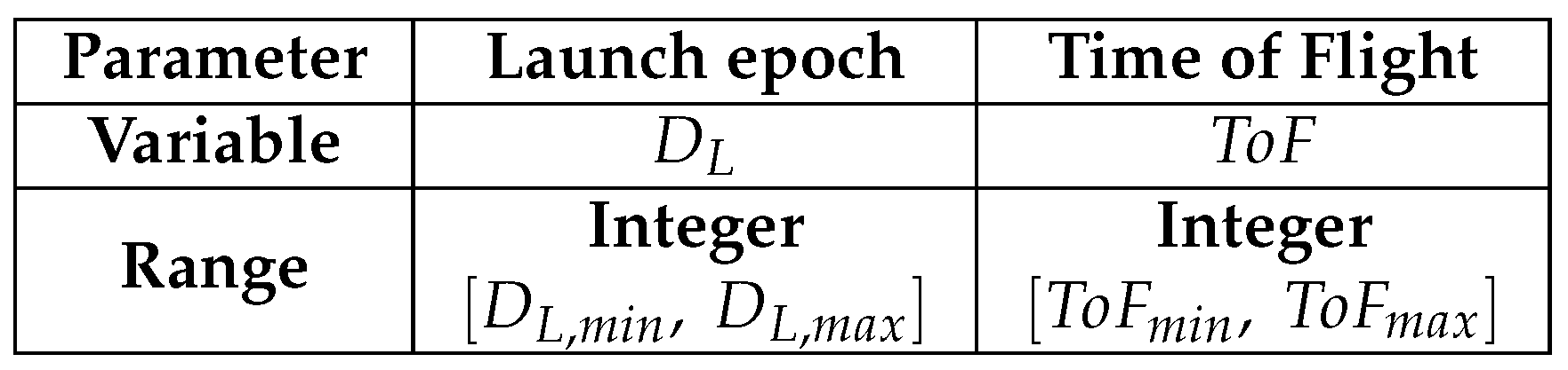
| Parameter | Value |
|---|---|
| [, ] | [1 January 2022, 31 December 2023] |
| [, ] | [1, 400] days |
| , | 0.2, 0.8 |
| 50 | |
| 3 |
| Parameter | Value |
|---|---|
| 2 October 2022 | |
| 248 days |
| Parameter | Value |
|---|---|
| Semimajor axis | 9376 km |
| Eccentricity | 0.015 |
| Inclination | 1.07 |
| RAAN | 208 |
| Argument of periapsis | 150 |
| Orbital period | 0.319 days |
| Maximum radius | 14 km |
| Parameter | Value |
|---|---|
| 300 km | |
| 0.95 | |
| [, ] | [1, 10] |
| [, ] | [1, 20] |
| [, ] | [1, 3] |
| 1 | |
| [, ] | [1, 1] s/km |
| 1 km/s | |
| 0.8 km/s | |
| 3 km |
| Parameter | Value |
|---|---|
| 305 km | |
| 0.948 | |
| p | 3 |
| q | 5 |
| 1.48 km | |
| 145 | |
| 66.7 | |
| 215 |
| Parameter | Value |
|---|---|
| , | [1, 3] km |
| 1 | |
| 3 km |
| Parameter | Value |
|---|---|
| 2.99 km | |
| 12.0 | |
| 16.0 | |
| 20.0 |
Publisher’s Note: MDPI stays neutral with regard to jurisdictional claims in published maps and institutional affiliations. |
© 2020 by the authors. Licensee MDPI, Basel, Switzerland. This article is an open access article distributed under the terms and conditions of the Creative Commons Attribution (CC BY) license (http://creativecommons.org/licenses/by/4.0/).
Share and Cite
Nallapu, R.t.; Dektor, G.; Kenia, N.; Uglietta, J.; Ichikawa, S.; Herreras-Martinez, M.; Choudhari, A.; Chandra, A.; Schwartz, S.; Asphaug, E.; et al. Trajectory Design of Perseus: A CubeSat Mission Concept to Phobos. Aerospace 2020, 7, 179. https://doi.org/10.3390/aerospace7120179
Nallapu Rt, Dektor G, Kenia N, Uglietta J, Ichikawa S, Herreras-Martinez M, Choudhari A, Chandra A, Schwartz S, Asphaug E, et al. Trajectory Design of Perseus: A CubeSat Mission Concept to Phobos. Aerospace. 2020; 7(12):179. https://doi.org/10.3390/aerospace7120179
Chicago/Turabian StyleNallapu, Ravi teja, Graham Dektor, Nalik Kenia, James Uglietta, Shota Ichikawa, Mercedes Herreras-Martinez, Akshay Choudhari, Aman Chandra, Stephen Schwartz, Erik Asphaug, and et al. 2020. "Trajectory Design of Perseus: A CubeSat Mission Concept to Phobos" Aerospace 7, no. 12: 179. https://doi.org/10.3390/aerospace7120179