Article

Emission Modes in Electrospray Thrusters Operating with High Conductivity Ionic Liquids

1
Plasma & Space Propulsion Laboratory, UCLA Mechanical and Aerospace Engineering, 420 Westwood Plaza, Los Angeles, CA 90095, USA
2
Electric Propulsion Lead, In-Space Propulsion Branch (RQRS), Air Force Research Laboratory, Edwards AFB, CA 93524, USA
3
LISA Microthruster Technology Lead, NASA Jet Propulsion Laboratory, California Institute of Technology, Pasadena, CA 91109, USA
*
Author to whom correspondence should be addressed.
Current address: UCLA Department of Mechanical and Aerospace Engineering, 420 Westwood Plaza, Los Angeles, CA 90095, USA.
Aerospace 2020, 7(10), 141; https://doi.org/10.3390/aerospace7100141
Submission received: 24 August 2020 / Revised: 17 September 2020 / Accepted: 22 September 2020 / Published: 25 September 2020
(This article belongs to the Special Issue Electric Propulsion)

Abstract

:
Electrospray thruster life and mission performance are strongly influenced by grid impingement, the extent of which can be correlated with emission modes that occur at steady-state extraction voltages, and thruster command transients. Most notably, we experimentally observed skewed cone-jet emission during steady-state electrospray thruster operation, which leads to the definition of an additional grid impingement mechanism that we termed “tilted emission”. Long distance microscopy was used in conjunction with high speed videography to observe the emission site of an electrospray thruster operating with an ionic liquid propellant (EMI-Im). During steady-state thruster operation, no unsteady electrohydrodynamic emission modes were observed, though the conical meniscus exhibited steady off-axis tilt of up to 15°. Cone tilt angle was independent over a wide range of flow rates but proved strongly dependent on extraction voltage. For the geometry and propellant used, the optimal extraction voltage was near 1.6 kV. A second experiment characterized transient emission behavior by observing startup and shutdown of the thruster via flow or voltage. Three of the four possible startup and shutdown procedures transition to quiescence within ∼475 μs, with no observed unsteady modes. However, during voltage-induced thruster startup, unsteady electrohydrodynamic modes were observed.

Graphical Abstract

1. Introduction and Background

Colloid electrospray thrusters are a class of electric propulsion device that produce thrust through electrostatic acceleration of charged liquid droplets. Application of an electrostatic field to a liquid results in electrohydrodynamic (EHD) phenomena classified into different modes based on emission behavior. Electrospray emission modes affect the performance and lifetime of colloid thrusters, and largely depend on bias voltage, propellant flow rates, and fluid properties. Thrust produced by an individual electrospray emitter is on the order of tens of nanonewtons to a single micronewton [1]. The high precision thrust offered by colloid thrusters makes them attractive for missions that require ultra-fine pointing and stability control, such as the Laser Interferometer Space Antenna (LISA) and Habitable Exoplanets (HabEx) Observatory [2,3]. The Colloid MicroNewton Thruster (CMNT) was jointly developed by Busek, Co. (Natick, MA, USA) and NASA for the Space Technology 7 (ST-7) payload aboard the European Space Agency (ESA) LISA Pathfinder mission [4,5]. LISA Pathfinder was the first mission to successfully demonstrate an electrospray thruster on orbit, where seven of the eight thrusters achieved the 2400 h lifetime target, and one thruster experienced a shorting failure after 1690 h [6]. Thruster lifetimes exceeding 40,000 h are required to achieve the scientific goals of the LISA and HabEx missions [2,7], so it is necessary to understand the specific mechanisms that limit thruster life.

1.1. Colloid Electrospray Thruster Lifetime

The CMNT flown on LISA Pathfinder operated with an ionic liquid propellant called 1-ethyl-3-methylimidazolium bis(triflouromethylsulfonyl)amide, which is abbreviated to EMI-Im. Ionic liquids are room temperature liquid salts that are attractive for spacecraft propulsion due to their negligible vapor pressure and high conductivity [8]. The negligible vapor pressure allows propellant to be directly exposed to vacuum without concern for evaporative mass loss or boiling. However, any emitted propellant that unintentionally strikes thruster grids will remain there indefinitely, accumulating until ultimately causing “backspray” or an electrical short [6]. For this reason, grid impingement due to accumulation of emitted propellant onto downstream extraction and acceleration grids is identified as a crucial inhibitor to thruster lifetime [6,9,10].
Thuppul et al. [9] presented an analytical electrospray thruster model that examined lifetime considerations based on geometry, operating conditions, and emission properties assuming purely axisymmetric emission. Figure 1a illustrates the two distinct mechanisms identified in Ref. [9] that result in grid impingement: overspray and plume expansion. Overspray accounts for species that diverge sufficiently from the axis near the emission site, such that they are on a trajectory that will impinge directly on the grids [9]. Additionally, radial plume expansion results from coulombic interactions, drag (if present), and fragmentation of emitted charged species in an interaction region immediately downstream of the jet breakup [11,12]. The induced radial motion due to plume expansion causes charged species to migrate away from the axis and intercept the grids. As such, Thuppul et al. addressed failure mechanisms resulting from axisymmetric plumes. In this study, we extend the consideration of life-limiting mechanisms by defining an additional mechanism of off-axis “tilted emission”. Tilted emission occurs when the emission site axis becomes non-coaxial with the ideal thrust axis. Figure 1b depicts tilted emission, θ t i l t , as a grid impingement mechanism distinct from plume expansion or overspray.
Substantial effort was invested in characterizing the emission behavior of cone-jetting devices, where emission instabilities play a key role in industrial applications, such as nanofilament electrospinning, or aerosol generation [13,14,15,16,17,18,19,20,21,22]. In the context of electrospray propulsion, research into electrospray emission behavior is comparatively less developed. In contrast to terrestrial electrospray applications, electrospray propulsion is most concerned with the life implications due to flux to the grids, therefore emission modes that lead to increased grid impingement need to be carefully investigated. Accordingly, our study focuses on the behavior of electrospray thruster conditions, i.e., highly viscous and conductive ionic liquids operating in vacuum. While electrospray thrusters were effectively engineered to meet the performance demands of scientific missions, research into the underlying physics governing the dynamic behavior of electrosprays is necessary to meet lifetime requirements. In the presented research, we experimentally resolve the electrospray thruster operating modes that may limit thruster lifetime.

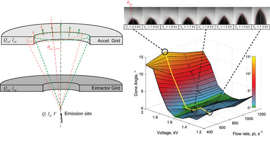
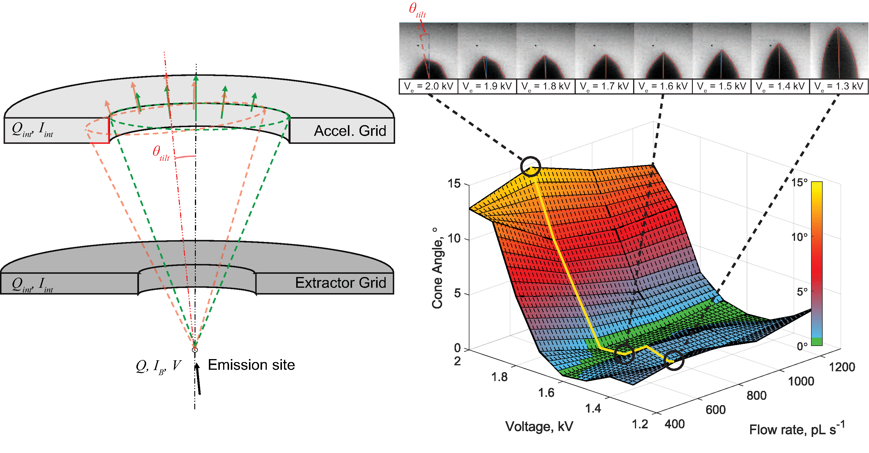
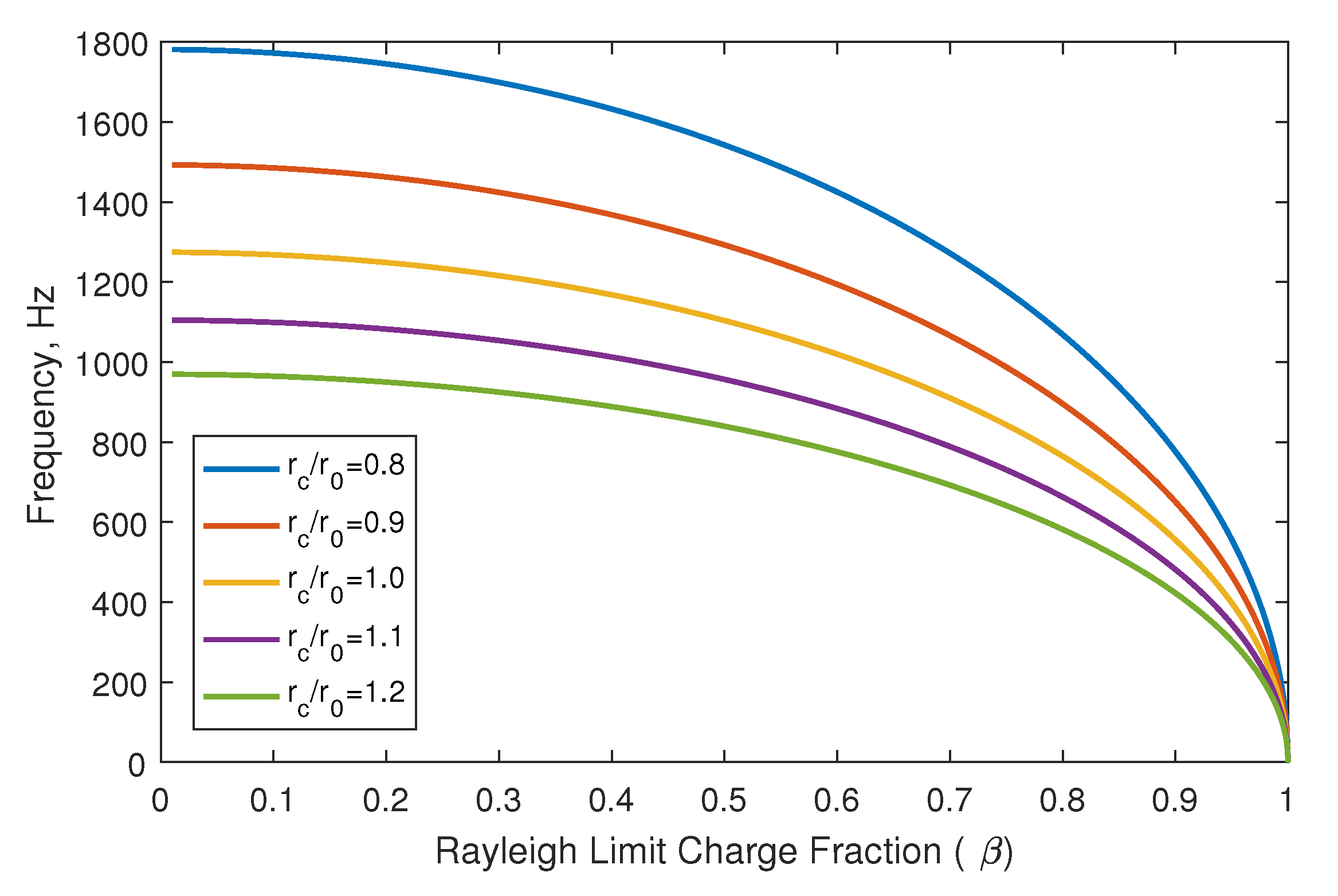
1.2. Electrospray Emission Modes

Electrospray emission is an electrohydrodynamic (EHD) process that occurs when a strong electric field is applied to a conductive meniscus. The applied electric traction force balances against surface tension, deforming the droplet’s curved meniscus into a cone. The ideal conical half-angle was analytically determined to be 49.3° by G. I. Taylor [26], hence the community’s adoption of “Taylor Cone” to describe an ideal electrified conical meniscus. The electric field is enhanced at the apex of the cone due to the tight radius of curvature, where an infinitely sharp cone will form a singularity in the electric field. An electrically forced jet forms in response to the field singularity, extracting fluid from the meniscus [27]. The conical shape of the meniscus may be sustained by feeding fluid to the emission site, often through use of a capillary tube and an active feed system, as is the case in Busek’s Colloid MicroThruster System (CMTS) [28,29].
Electrospray operating modes depend on the flow rate and biasing voltage. The wealth of research on electrospray mode classification led to inconsistent nomenclature throughout literature. To avoid confusion, we adopt the generalized emission mode classifications used by Rosell-Llompart, Grifoll, and Loscertales [30]. “Periodic EHD modes” are characterized by axisymmetric pulsating emission, and can be further subclassified into “electro-dripping”, “spindle”, or “intermittent cone-jet” modes. Only the intermittent cone-jet mode is relevant to the presented results, and will be discussed later in the article.
The “steady EHD modes” are classified as continuous and uninterrupted emission of one or more jets that are narrower than the diameter of the capillary. Rosell-Llompart et al. [30] define two subsets of steady EHD emission as “steady cone-jet mode” and “multi-jet mode”. Steady cone-jet emission is the preferred mode for electrospray thruster lifetime, as it minimizes grid impingement. Multi-jet mode occurs at elevated bias voltages, and is characterized by the formation of more than one jet staked to the edge of the emitter, resulting in substantial grid impingement. An additional mode occurs in the transition between cone-jet and multi-jet modes called “skewed cone-jet”, which tilts off the capillary’s axis of symmetry [17,31]. Skewed cone-jet emission emerges when the applied voltage is increased above the potential required for steady cone-jet mode. Ultimately, a high enough potential will cause formation of a second jet, marking the transition into multi-jet mode. The electrically forced jet that forms at a cone’s apex is an inherently unstable flow, which ultimately results in breakup of the jet into droplets [18,19]. Rosell-Llompart et al. [30] define two cone-jet sub-modes as the axisymmetric “varicose jet breakup” and non-axisymmetric “whipping jet”. Varicose jet breakup is preferred for electrospray emission, as it minimizes grid impingement.
The electrospray emission modes discussed above constitute a brief survey of the complex EHD phenomena that occur in electrosprays, yet the definitions are useful for understanding how EHD modes have significant implications for electrospray lifetime. Ensuring that the thruster remains in the bounds of steady cone-jet mode will maximize thruster life. However, flight data from the ST-7 mission show that system-commanded thrust changes result in overshoot and undershoot events that may last for tens of seconds, which may cause the thruster to deviate from the preferred steady cone-jet mode [6,32]. The experiments described in the following sections seek to characterize the dominant emission modes when electrospraying EMI-Im in vacuum, and to observe thruster behavior during the two worst-case command transients: startup and shutdown. Understanding ionic liquid emission behavior will provide insight into the primary mechanisms that cause grid impingement, which is critical to predicting the lifetime of colloid electrospray thrusters.

2. EMI-Im Electrospray Emission Mode Classification Experiments

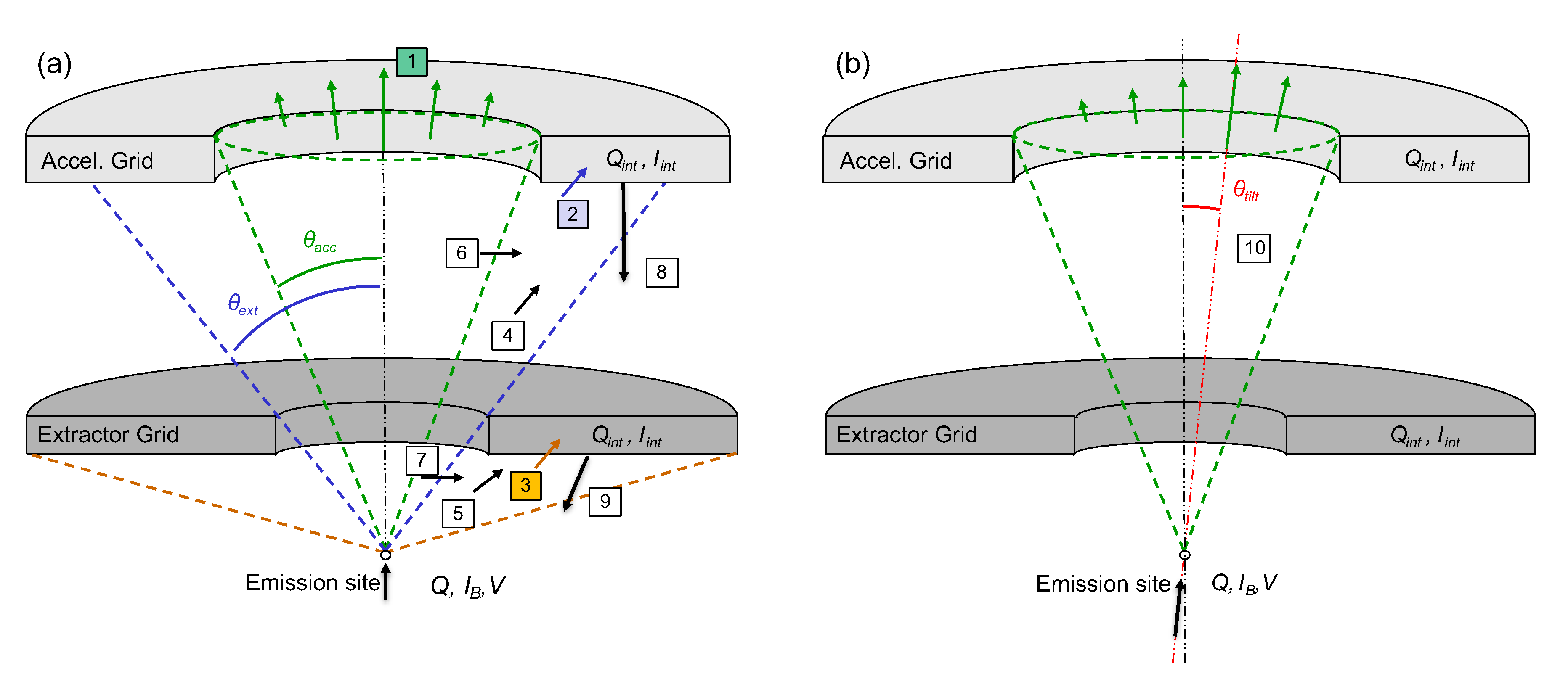
2.1. Experiment Setup

The UCLA Plasma and Space Propulsion Lab developed the Highly Optimizable Apparatus for Groundbreaking Investigation of Electrosprays (HOAGIE) as a testbed to study the dynamics and lifetime of electrospray thrusters [33]. A diagram of the HOAGIE experiment configuration used in the presented study is shown in Figure 2. The thruster consisted of an emitter biased with respect to a grounded extractor using a high voltage power supply—no accelerator grid was used in the experiment. Since the ionic liquid propellant, EMI-Im is the subject of the presented studies, relevant fluid properties are listed in Table 1. Propellant flow is controlled by a pressure-over-fluid (POF) feed system, where an isolated reservoir is pressurized with dry nitrogen using mass flow controllers to achieve flow rate accuracy of ∼0.1%. The volumetric flow rate is determined from the reservoir pressure by an Ohm’s Law analogy [34],
Q I L = ( Δ P ρ g Δ y ) R h ,
where Q I L is the volumetric flow rate, Δ P is the pressure difference between the ionic liquid reservoir and the vacuum vessel, ρ is fluid density, g is the gravitational constant, Δ y is the vertical distance between the emitter tip and reservoir, and R h is the hydraulic resistance of the emitter. The hydraulic resistance was measured by using a flow controller to record the pressure and volumetric flow rate of dry nitrogen through the emitter from a fixed test volume. The HOAGIE chamber achieves a base pressure of 5 × 10⁻⁴ Pa, which is negligible compared to the reservoir pressure of ∼103 Pa to 104 Pa, so Δ P is entirely controlled by the ionic liquid reservoir pressure. Volumetric flow rate was controlled by a closed-loop feedback system implemented in LabVIEW, where Δ P was adjusted by two flow controllers: one connected to a dry nitrogen tank and another connected to a vacuum pump. The EMI-Im propellant was conditioned by exposure to low vacuum for at least 24 h prior to experiment operations to ensure negligible water and gas content. Dry propellant is necessary to avoid conflating unstable emission related to bubble formation with unstable emission due to EHD phenomena [23].
The platinum emitter and stainless steel extractor geometries used in this experiment are identical to those used in the ST-7 Disturbance Reduction System (DRS) [4,6,32,39,40,41]. For the presented studies, a 2 MHz high-speed camera (Photron SA-Z) was used in conjunction with a long-distance microscope optical system developed in-house to observe the emission site. The camera was operated at 300 kHz for the presented experiments. Additional diagnostics are available in HOAGIE, such as a Quartz Crystal Microbalance (QCM) mounted on the “Probe Arm” labelled in Figure 2. The QCM may be angularly or linearly swept through the plume at a range of distances (∼10 cm) from the emitter, to measure spatially resolved mass flux. Angular mass flux sweeps at a fixed radius (14 cm) through the central plane of the plume were recorded in parallel with the data presented in this study, full details of which can be found in Ref. [42].

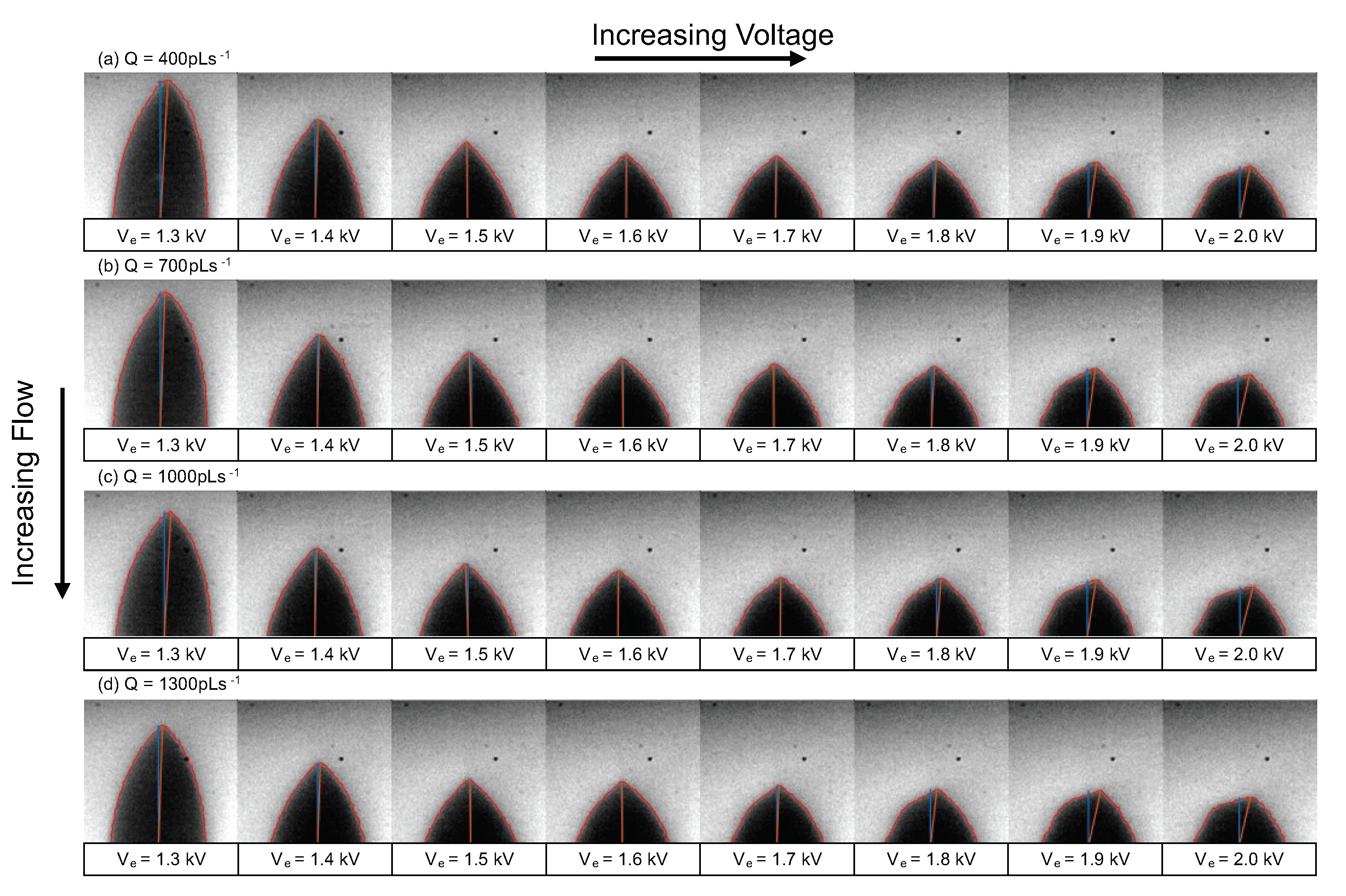
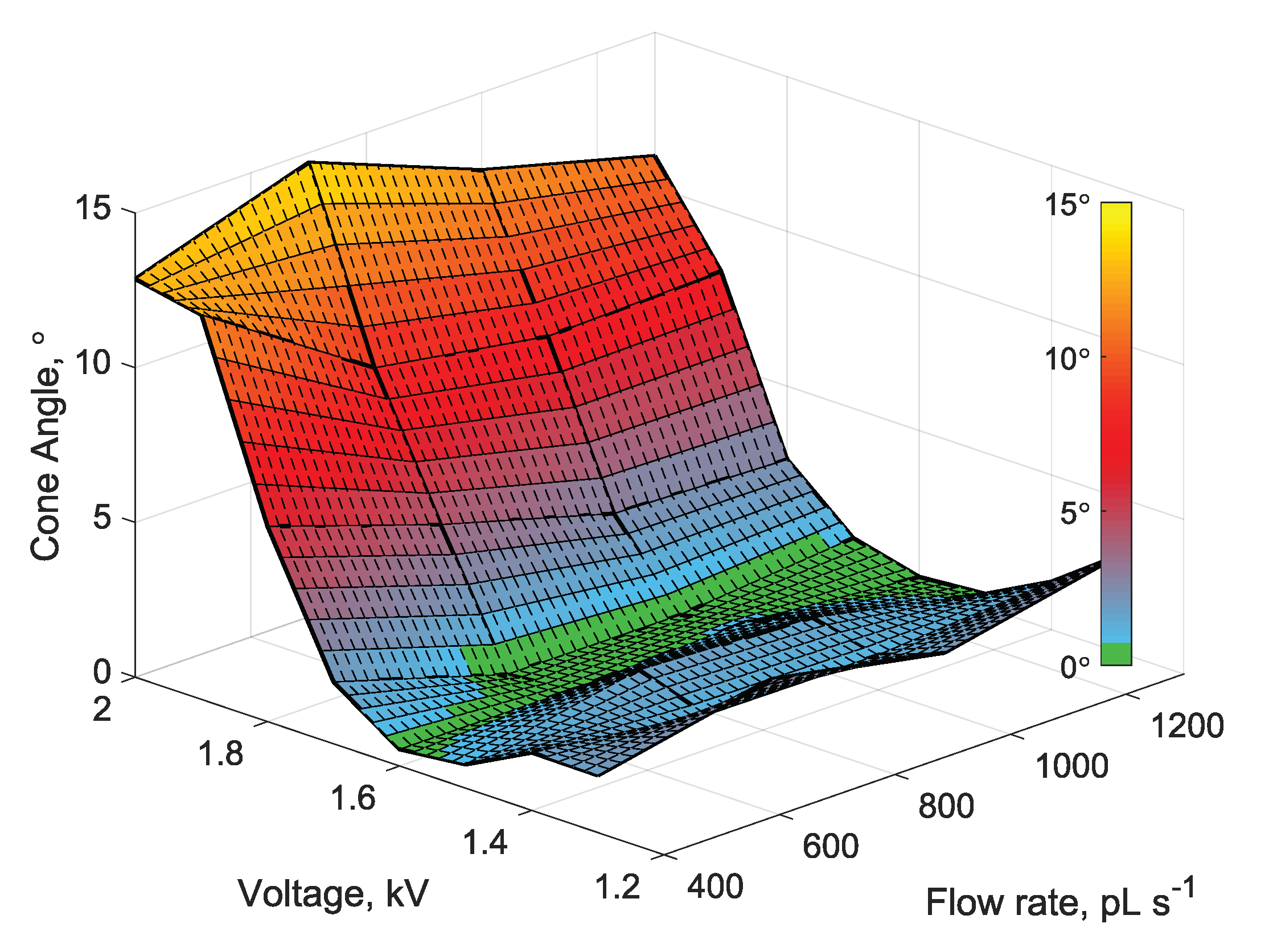
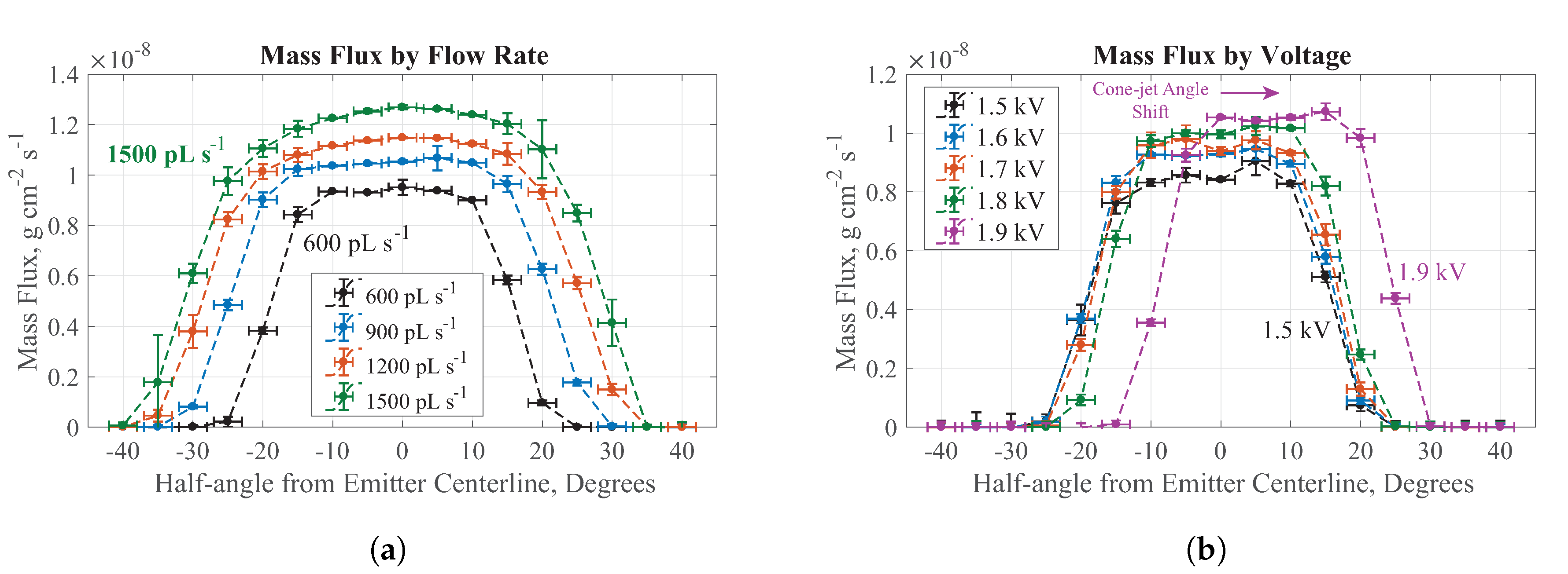
2.2. Steady-State Emission: Results

A map of the steady-state emission behavior was obtained by taking high-speed videos of the emission site while parametrically sweeping the emitter bias voltage and propellant flow rate. Flow rate was commanded from 400 pL s−1 to 1300 pL s−1 in 300 pL s−1 steps, while voltage was swept from 1.3 kV to 2.0 kV in 100 V steps at each flow setpoint. The flow rate range was chosen to span nominal operating setpoints, and the voltage range was chosen between the observed minimum extraction voltage and the maximum voltage output of the power supply.
No unsteady EHD modes were observed over the entire range of operating conditions—the emission site only exhibited steady EHD emission behavior. Steady cone-jet emission appears to be axisymmetric between 1.5 kV and 1.7 kV, confirming the nominal 1.6 kV extraction voltage selected by Busek/JPL is indeed optimal for the CMNT [39]. As voltage increased from the nominal extraction voltage, the cone-jet began to tilt, indicating a skewed cone-jet mode. Cone-tilt appears to have a strong dependence on the emitter voltage, with the greatest tilt angles occurring at the upper bound of voltage setpoints. However, skewed cone-jet mode also occurs below 1.5 kV, where tilt angles are small and the meniscus takes an ogival shape. Images of the emitter at each setpoint are shown in Figure 3. The angle of the conical meniscus with respect to the ideal thrust axis, θ c , was plotted against the emitter voltage and applied flow rate in Figure 4. The emission angle’s lack of an apparent dependence on flow rate is significant, as thrust is controlled with propellant flow rate adjustment [39]. Therefore, at a fixed nominal extraction voltage, a colloid thruster should not experience skewed cone-jet modes over its nominal flow ranges.

2.3. Steady-State Emission: Discussion

The skewed cone-jet mode observed in the emission map exemplifies the grid impingement mechanism of “tilted emission,” which we have defined as deviation of the emission axis to orientations that are non-coaxial with the ideal thrust axis. The motivation for this distinction is the difference between how each mechanism induces radial motion in the emitted charged species. Overspray results from radial velocity imparted onto charged species at their inception, which occurs at the emission site at the apex of the conical meniscus. Plume expansion results from radial forces imparted on charged species after inception, downstream of the emission site [11,12]. Tilted emission represents a complete angular shift of the cone’s axis, causing all emitted species’ velocities to have an additional radial component in one direction.
The range of flow rate and emitter voltage setpoints performed in the presented experiment are similar to those used in the ethanol stability experiments reported by Wright, Thuppul, and Wirz [34]. When compared to ethanol, the “stability island” for EMI-Im steady cone-jet mode appears to be much larger than that of ethanol. Furthermore, the nature of axial asymmetries differs between the two experiments: EMI-Im exhibits steady skewed cone-jet mode, whereas ethanol exhibits an unsteady whipping of the cone-jet. To understand why ionic liquid electrosprays exhibit different behavior, it is useful to discuss the motion of fluid in a conical meniscus and electrified jet. Toroidal and helical flow patterns were extensively studied in Taylor cones [44,45,46,47,48]. Toroidal flow patterns manifest when the characteristic velocity driven by electrical shear stresses at the cone surface is greater than fluid velocity due to supplied flow [44,48]. Helical motion may manifest due to azimuthal instabilities, whose growth rates depend on viscosity and conductivity of the fluid [47]. Barrero et al. [48] analytically derived a relationship for local fluid velocity induced by interfacial electric stresses for a flow pattern that exhibits purely toroidal motion:
U γ ε 0 I 2 d n 3 κ 2 μ 2 1 / 2 ,
where γ is surface tension, ε 0 is the vacuum permittivity, I is the emitter current, d n is the inner diameter of the capillary, κ is conductivity, and μ is viscosity. Reynolds number is then given by:
R e = ρ U d n μ ρ 2 γ ε 0 I 2 d n κ 2 μ 4 1 / 2 ,
where ρ is the fluid density. Using flow rates reported by Wright, Thuppul, and Wirz [34], emitter current can be estimated using the universal scaling laws derived by de la Mora and Loscertales [49]:
I = f ( ε r ) γ Q κ ε r 1 / 2 ,
where f ( ε r ) is an empirical function with the form [50]:
f ( ε r ) = 449 0.21 ε r + 157 ε r 1 / 6 + 336 ε r 1 / 6 .
Shtern and Barrero [47] determined a critical Reynolds number of 6.92 for the onset of azimuthal flow in the cone. Substituting ethanol’s fluid properties and the 0.75 nL s−1 flow rate reported in Ref. [34] into Equations (3)–(5), we estimate a Reynolds number of approximately 23.93. In the presented EMI-Im experiments, Reynolds number was found to be approximately 10−5 for all setpoints. The μ 2 and κ 1 dependency in Equation (3) indicates that the highly viscous and conductive nature of ionic liquids help to suppress azimuthal instabilities that lead to whirling motion in the cone flow. The unsteady whipping cone-jet observed when emitting ethanol in Ref. [34] is likely a superposition of a whirling-cone flow pattern with the skewed cone-jet emission mode. With EMI-Im, where the whirling motion in the cone is suppressed, only the skewed cone-jet mode arises.
By equating the electric field produced by the jet and cone at their intersection, Gamero and de la Mora determine the characteristic radius of the jet to be as follows [51]:
r j ( Q I L ε 0 ) κ 1 / 3
Substituting a nominal flow rate of 1000 pL s−1 and EMI-Im conductivity of 0.921 S m−1, the characteristic radius of the jet is estimated to be 21 nm, which is beyond the resolution of the implemented LDM, so it cannot be directly observed with our experiment. We note, however, that Hohman et al. [18] show that even small increases in viscosity of a fluid will act to suppress the whipping-jet instability growth, allowing varicose breakup mode to dominate. Nayak et al. [52] also experimentally observed that decreasing the viscosity of a working fluid results in transitions to the whipping jet breakup mode. Therefore, varicose jet breakup should be the dominant breakup mode for jets emitted from a steady EHD mode. The overall enhanced stability of EMI-Im electrosprays can be directly attributed to the high viscosity and conductivity of the fluid.
In addition to grid impingement, another consequence of skewed cone-jet emission is tilting of the thruster’s plume. Thuppul et al. [42] reported a loss of plume symmetry at higher extraction voltages during parametric measurements of the thruster plume profile, which are reproduced in Figure 5. The plume profile characterization by Thuppul et al. [42] was performed on the same experimental setup and thruster geometry as the presented study.
The cone tilt angles shown in Figure 3 and Figure 4 represent the projection of the true polar tilt angle into the object plane of the LDM. In the HOAGIE setup shown in Figure 2, the plume measurement plane is orthogonal to the LDM object plane. The fact that asymmetry is observed in both planes indicates that neither measurement shows the true direction of tilt. However, due to the orthogonality of the two measurements, some simple geometry can be employed to estimate the cone tilt angle in three-dimensional space.
Assuming the plume’s shift angle is a projection of the skewed cone-jet tilt angle, an arbitrary cone height, h c , can be assigned in Cartesian coordinates. Given the cone tilt angles estimated from each plane, ϕ 1 and ϕ 2 , the following equations can be used to estimate true cone tilt in spherical coordinates:
x p = h c ( tan ϕ 1 ) ,
y p = h c ( tan ϕ 2 ) ,
θ c = arctan ( x p / y p ) ,
ρ c = x p 2 + y p 2 + h c 2 ,
ϕ c = arccos ( h c / ρ c ) ,
where x p is the projected x-coordinate, y p is the projected y-coordinate, θ c is the azimuthal angle, ρ c is the radial distance, and ϕ c is the actual cone-tilt angle. The two setpoints of overlap between the plume measurements in Ref. [42] and the presented steady-state parametric sweep are at an emission voltage of 1.8 kV and 1.9 kV for a fixed flow rate of 600 pL s−1. Using Equations (7)–(11), the polar angle and azimuthal angles of cone tilt are reconstructed and shown in Table 2. The presented reconstruction analysis offers an approximation of actual direction of cone tilt, indicating that the extent of polar tilt can be slightly greater than observed in a two-dimensional image. The possible dependence of azimuthal angle on emitter bias voltage merits further study.
The presented technique of reconstructing three-dimensional tilt illustrates the need to consider emission pointed towards or away from the camera. Using plume profile skew reported in Ref. [42] as an orthogonal source of data for estimated cone tilt conveniently allows for an approximation of the true cone-tilt direction. However, simultaneous imaging of the emitter site from two angles is necessary to provide accurate measurements for reconstructing cone-tilt angle in three-dimensional spherical coordinates.

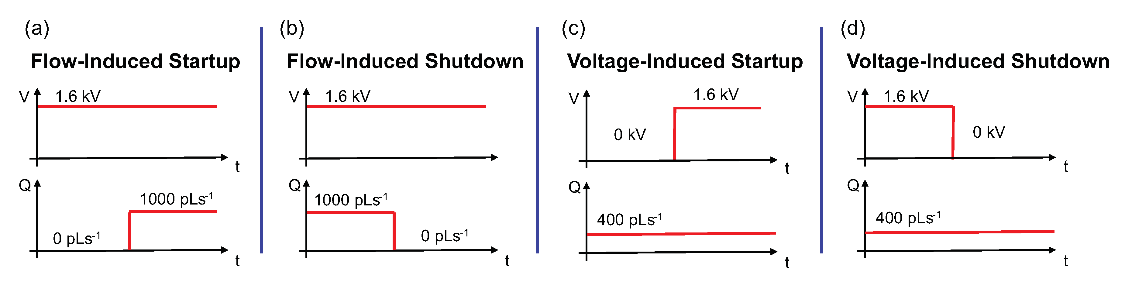
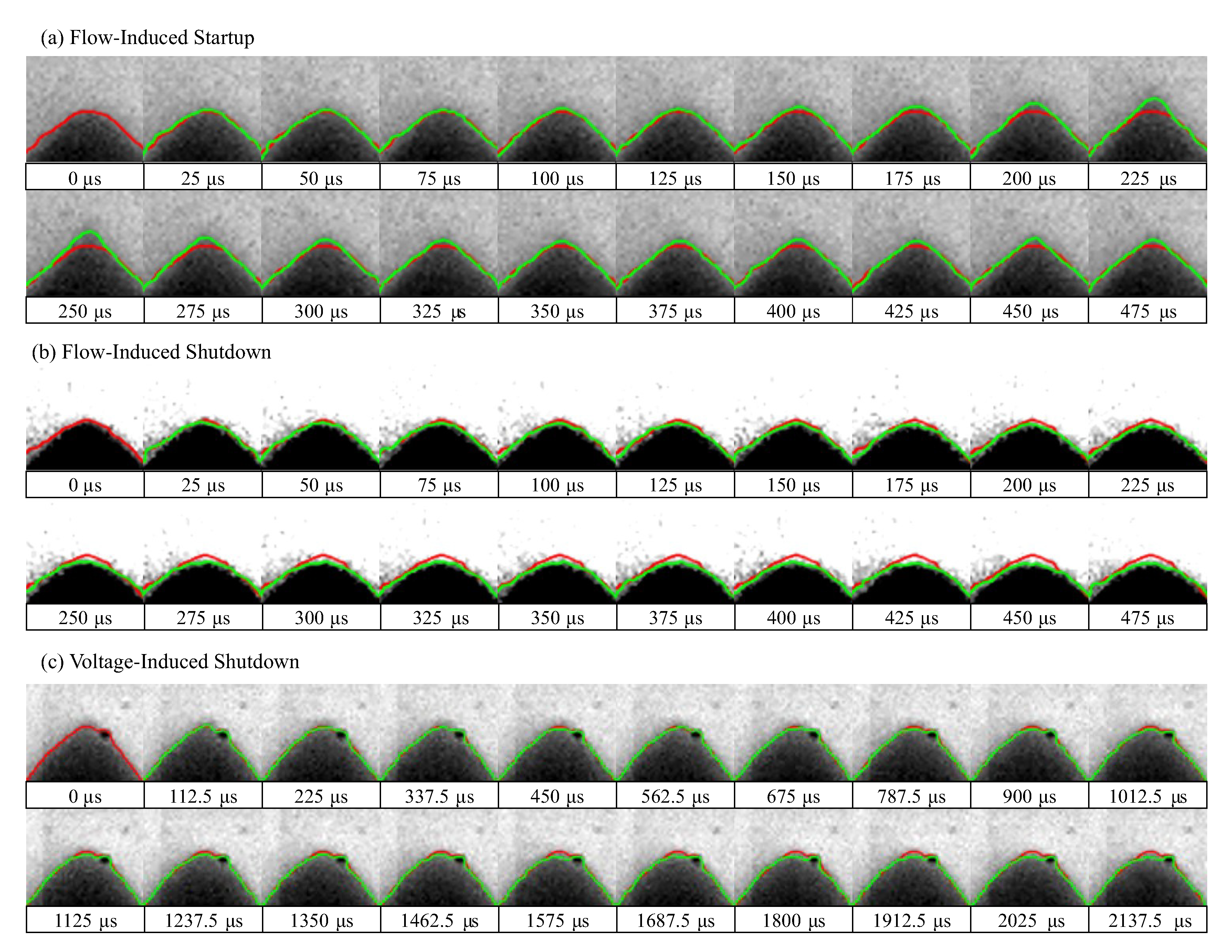
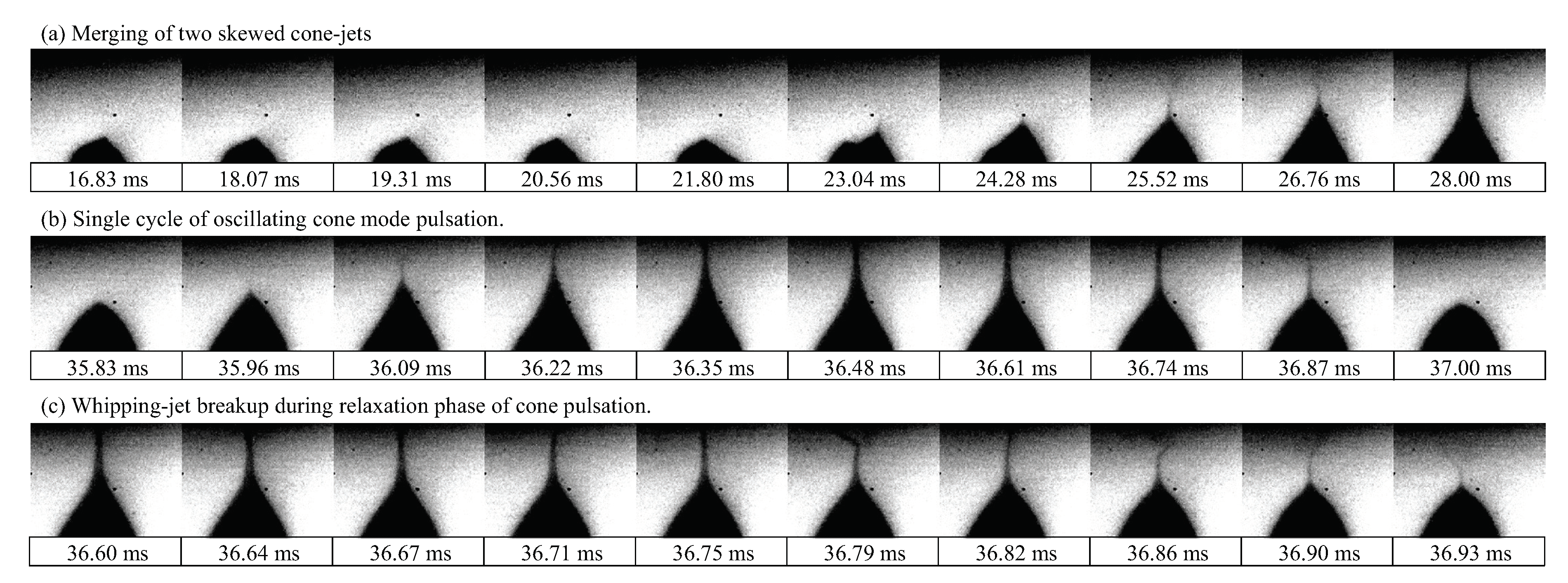
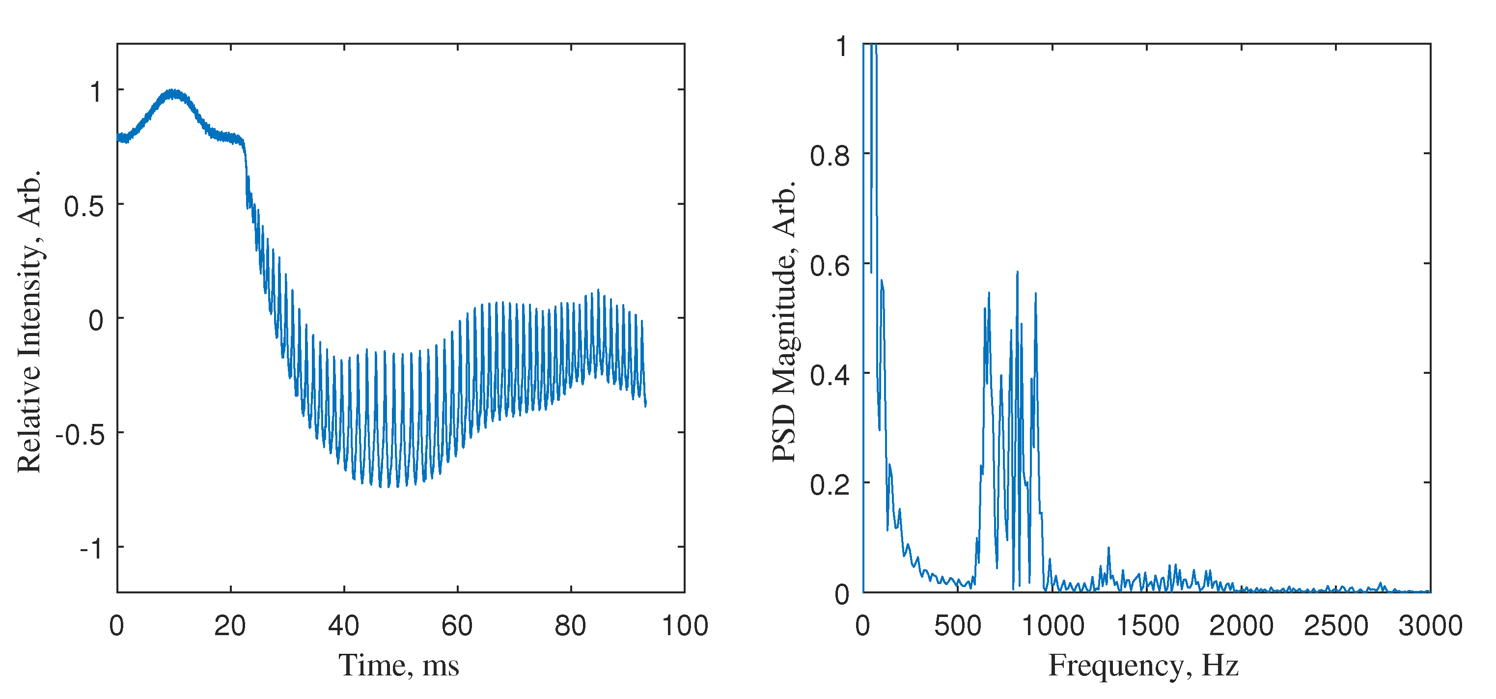
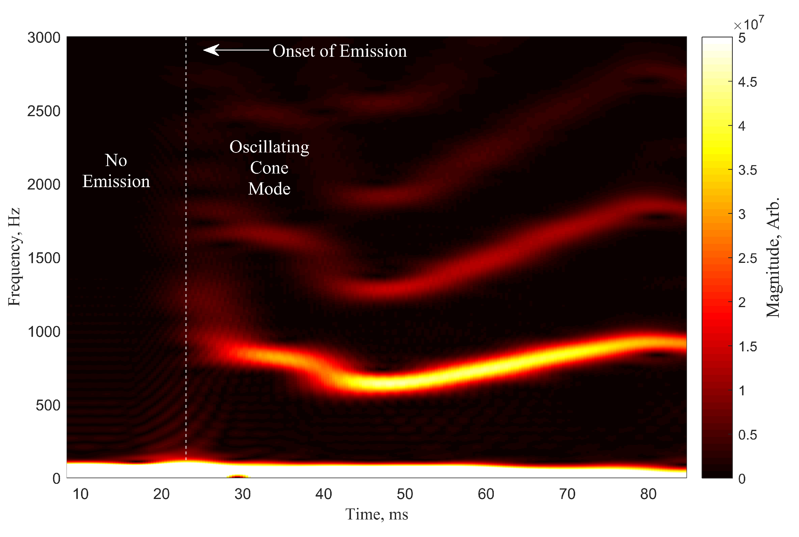
2.4. Transient Emission: Results

Transient emission experiments were performed by capturing the onset and cessation of emission during thruster startup and shutdown, which can be induced through large step-changes in either the voltage or flow rate. Flow-induced transient experiments involve maintaining a fixed 1.6 kV emitter voltage and either rapidly increasing propellant flow rate from 0 pL s−1 to 1000 pL s−1, or rapidly decreasing flow to 0 pL s−1. Voltage-induced transient experiments instead involve maintaining a steady 400 pL s−1 flow rate, while rapidly applying or removing a 1.6 kV bias voltage. Qualitative plots of the commanded flow and voltage during the described transient emission tests are shown in Figure 6. The flow-induced and voltage-induced transients replicate nominal and off-nominal thruster start/stop conditions, respectively.
Results for flow-induced startup are shown in Figure 7a. As propellant flows from the capillary, the resulting meniscus deforms into a conical shape due to the applied electric field. Eventually, the meniscus height reaches a point where the stresses at the tip permit formation of a steady cone-jet. A slight overshoot in cone height is observed during the emission-onset transient. The emission reaches a quiescent height approximately 150 μs after the onset of emission, yet remains in steady cone-jet mode throughout the transient relaxation period.
Flow-induced shutdown results are shown in Figure 7b. When flow is cut off to the emitter, the jet continues to extract propellant from the cone until the volume can no longer sustain emission. The jet ceases emission within 375 μs, but the meniscus continues to recede over the next 1000 μs to 2000 μs. Voltage-induced shutdown shown in Figure 7c appeared to behave identically to the flow-induced shutdown case, where shutdown occurred rapidly once the voltage bias was removed.
Voltage-induced startup exhibited extremely unstable behavior, transitioning through several different emission modes. Due to the constant flow of propellant to the emitter prior to application of a bias voltage, a large droplet of propellant had accumulated on the side of the emitter. Images of the voltage-induced onset of emission are shown in Figure 8a. Immediately after stepping the voltage to 1.6 kV, a skewed cone-jet formed away from the capillary-axis. Approximately 10 ms after onset of the first off-axis cone-jet, a large droplet emerged from the reservoir of excess propellant, producing a secondary cone-jet emitting at an angle opposite the primary cone-jet. Approximately 5 ms later, the primary and secondary cone-jets merged into one axisymmetric emission site that immediately entered intermittent cone-jet mode pulsation. Figure 8b shows a single cycle of pulsation.
Upon entering intermittent cone-jet mode, the jet transitioned into a whipping breakup mode. Figure 8c shows an image sequence isolating the whipping jet breakup mode that grew in oscillation frequency during the relaxation phase of the pulsation cycle. Whipping jet breakup clearly causes significant overspray, with non-axial emission of large droplets observed as the jet retracted. The scale of these images was found to be 3.76 μm/pixel, so the observed droplets must be on the order of 0.1 μm to 1 μm. A one-dimensional time-domain representation of the high-speed video signal is obtained by taking the aggregate pixel intensity of each frame:
Y i ( t ) = x y I ( x , y , t ) ,
where I ( x , y , t ) is the pixel intensity at indices x and y, at time t. Figure 9 shows the time-domain signal and power spectral density of the one-dimensional pixel intensity signal. The strong peak at < 60 Hz corresponds to the vibration of the camera and chamber. The dominant frequency band from 600 Hz to 900 Hz corresponds to the intermittent cone-jet instability, where the weaker band from 1 kHz to 3 kHz corresponds to the whipping jet breakup. Figure 10 shows a spectrogram of the pixel intensity that was generated using 16.6 ms bins, and a triangular windowing function with 16.3 ms overlap. The spectrogram shows a ∼800 Hz pulsation that begins at the onset of emission at ∼23 ms, and varies by ∼200 Hz over time. Frequency variation may indicate an underdamped system response to the voltage step transient. The bands greater than 1 kHz correspond to whipping-jet breakup during the relaxation phase of pulsation. The pulsation eventually damps out after several hundred milliseconds as the accumulated propellant is cleared, and reaches stability after the presented record time.

2.5. Transient Emission: Discussion

Flow-induced startup and shutdown rapidly traverse the range of conditions that should result in unsteady EHD modes, yet emission appeared entirely steady during the experiment campaign. To address this, we will discuss the two different regimes of the intermittent cone-jet mode. The first pulsation regime, often referred to as the “choked-jet” mode, occurs when the supplied flow rate ( Q s ) is less than a minimum flow rate ( Q m ) , and the emitter bias voltage ( V e ) is greater than the minimum extraction voltage ( V m ) [15,16,53]. Chen et al. [15] showed that choked-jet pulsation frequency scales as:
f c j κ V e 2 ε r μ h 2 L ρ d n 5 γ 1 / 2 ,
where L is the emitter length, and h is the extractor-to-emitter separation distance. Inserting the emitter dimensions and fluid properties for EMI-Im in Equation (13), the choked-jet pulsation mode frequency is greater than 825 kHz. Therefore, it is possible that choked-jet pulsation emission occurs during flow-induced startup and shutdown at higher frequencies than are resolvable with the given diagnostics. A lower bound of 300 kHz on any pulsation frequency during the startup transient is concluded. Improved high-speed diagnostics are necessary to determine whether the thruster enters a brief period of pulsating choked-jet emission. To observe possible choked-jet emission, the presented analysis suggests a spatial resolution on the order of ∼1 nm and temporal resolution of <10 ns is required.
The second pulsation regime, known as the “oscillating cone” mode, occurs when Q s > Q m and V e < V m [20,27]. Marginean et al. [20] derived a relationship between the oscillating cone pulsation frequency and the Rayleigh limit charge fraction:
f o c = 2 γ ( 1 β 2 ) π 2 ρ r c 3 ,
where r c is the radius of the cone’s tip during the relaxation period of pulsation, and β is the ratio of charge to the theoretical Rayleigh-limit. For flow-induced startup and shutdown, the conditions for oscillating cone mode are not met. However, in the case of the voltage-induced startup, a droplet of accumulated propellant on the emitter has a negligible hydraulic resistance. Therefore, the local effective flow rate during the voltage-induced startup is very high, satisfying the Q s > Q m condition for oscillating cone pulsation. Once pulsation begins, the meniscus envelopes the emitter’s tapered edge, so r c is taken to be approximately the capillary’s outer radius. To explore the approximate scaling of f o c , we substitute an assumed range of β between 0 and 1. Equation (14) is plotted in Figure 11 over several values for r c . At the observed oscillation frequency, β lies between 61% and 88%, which is reasonable in the context of other published pulsating cone-jet charge measurements [20,54]. The good agreement between the observed behavior during voltage-induced startup in EMI-Im electrosprays and the frequency scaling derived by Marginean et al. [20] indicates that the thruster’s behavior fits the oscillating cone mode classification.

3. Conclusions

Identifying electrospray thruster emission modes is critical to estimating the lifetime and performance of colloid electrospray thrusters. The results of our parametric stability study of an EMI-Im electrospray show optimal behavior (i.e., axisymmetric, steady cone-jet mode) between emitter bias voltages of 1.5 kV to 1.7 kV. Tilted emission caused by skewed cone-jet mode, where the conical meniscus exhibits steady off-axis tilt of up to 15°, was observed increasingly below (1.3 kV to 1.5 kV) and above (1.7 kV to 2.0 kV) the optimal bias range of 1.5 kV to 1.7 kV, and was most pronounced at the highest voltages. Emission tilt was essentially independent of flow rate over the full range of 400 pL s−1 to 1300 pL s−1, which is significant since thrust is often controlled by propellant flow rate.
The observation of skewed cone-jet mode motivated our definition of “tilted emission” to describe deviation of the emission site axis away from the thrust axis, which represents an additional distinct mechanism that should be considered when determining grid impingement. Tilted emission may have additional consequences beyond lifetime considerations for electrospray thrusters. For example, skewed cone-jet mode can cause asymmetric plume profiles, off-axis thrust, and potentially increased spacecraft interactions.
Regarding transient emission modes, during flow-induced startup and shutdown conditions, a steady cone-jet emerges and undergoes a slight overshoot without exhibiting unstable modes, settling to a constant height after approximately 150 μs. During voltage-induced shutdown conditions, the steady cone-jet is extinguished within 375 μs. While no unsteady behaviors were observed during these commanded transients, improved resolution of diagnostics could resolve possible unsteady modes. Our analysis indicates a spatial resolution on the order of ∼1 nm and temporal resolution of <10 ns is required.
Voltage-induced startup exhibits extremely unstable emission, with both unsteady oscillating-cone mode and whipping-jet breakup mode present. Unstable behavior during voltage-induced startup is likely attributed to the accumulation of excess propellant at the capillary tip. The hydraulic resistance of a stagnant droplet is negligible, so it can produce an arbitrarily high flow rate when the bias voltage is applied. The forced-voltage response of the system suggests that electrosprays using ionic liquids with high viscosity and conductivity exhibit stable cone-jet emission over a much wider range of flow rates. It is notable that even when forcing the thruster into unsteady modes through large perturbations, the system quickly settles to a steady cone-jet emission state.

Author Contributions

Conceptualization, N.M.U., A.L.C., A.T., P.L.W., D.Q.E., J.Z. and R.E.W.; Data curation, J.Z. and R.E.W.; Formal analysis, N.M.U., A.L.C. and P.L.W.; Funding acquisition, D.Q.E., J.Z. and R.E.W.; Investigation, N.M.U., A.L.C. and A.T.; Methodology, N.M.U., A.L.C., A.T., P.L.W., D.Q.E., J.Z. and R.E.W.; Project administration, D.Q.E., J.Z. and R.E.W.; Resources, D.Q.E., J.Z. and R.E.W.; Software, N.M.U. and A.L.C.; Supervision, D.Q.E., J.Z. and R.E.W.; Validation, N.M.U., A.L.C. and A.T.; Visualization, N.M.U., A.L.C., A.T. and P.L.W.; Writing—original draft, N.M.U. and A.L.C.; Writing—review & editing, N.M.U., A.L.C., A.T., P.L.W., D.Q.E., J.Z. and R.E.W. All authors have read and agreed to the published version of the manuscript.

Funding

This research was funded by grants from NASA/JPL award number 1580267:3, the Air Force Research Laboratory award number 16-EPA-RQ-09, and NASA Space Technology Research Fellowship grant 80NSSC18K1194. A portion of the research was carried out at the Jet Propulsion Laboratory, California Institute of Technology, under a contract with the National Aeronautics and Space Administration (80NM0018D0004). Distribution Statement A: Approved for Public Release; Distribution is Unlimited, PA Clearance 20356.

Acknowledgments

The authors would like to thank Colleen Marrese-Reading, David Conroy, and Stephanie Leifer from NASA JPL, Daniel Courtney and Nathaniel Demmons from Busek, and Michael Natisin from AFRL for their insights. The authors would also like to thank undergraduate researchers Tim Simka and Josue Castillo for their efforts in helping perform experiments.

Conflicts of Interest

The authors declare no conflict of interest. The funders had no role in the design of the study; in the collection, analyses, or interpretation of data; in the writing of the manuscript, or in the decision to publish the results.

Abbreviations

The following abbreviations are used in this manuscript:
EHDElectrohydrodynamic
CMTSColloid Microthruster System
UCLAUniversity of California, Los Angeles
HOAGIEHighly Optimizable Apparatus for Groundbreaking Investigations in Electrosprays
EMI-Im1-ethyl-3-methylimidazolium bis(triflouromethylsulfonyl)amide
DRSDisturbance Reduction System
ST-7Space Technology 7
LDMLong-Distance Microscope
POFPressure-over-fluid
QCMQuartz Crystal Microbalance

References

  1. Legge, R.S.; Lozano, P.C. Electrospray Propulsion Based on Emitters Microfabricated in Porous Metals. J. Propuls. Power 2011, 27, 485–495. [Google Scholar] [CrossRef]
  2. Mennesson, B.; Kiessling, A.; Warfield, K. HabEx: Habitable Exoplanet Observatory Interim Report; Technical Report; Astronomy, Physics and Space Technology Directorate, Jet Propulsion Laboratory: Pasadena, CA, USA, 2018. [Google Scholar]
  3. Demmons, N.R.; Lamarre, N.; Ziemer, J.K.; Parker, M.; Spence, D. Electrospray Thruster Propellant Feedsystem for a Gravity Wave Observatory Mission; American Institute of Aeronautics and Astronautics: Reston, VA, USA, 2016. [Google Scholar] [CrossRef]
  4. Hruby, V.; Spence, D.; Demmons, N.; Roy, T.; Ehrbar, E.; Zwahlen, J.; Martin, R.; Ziemer, J.; Connolly, W.; Rhodes, S. ST7-DRS colloid thruster system development and performance summary. In Proceedings of the 44th AIAA/ASME/SAE/ASEE Joint Propulsion Conference & Exhibit, Hartford, CT, USA, 21–23 July 2008; pp. 1–32. [Google Scholar] [CrossRef]
  5. Ziemer, J. Performance of Electrospray Thrusters. In Proceedings of the International Electric Propulsion Conference, Ann Arbor, MI, USA, 20–24 September 2009. [Google Scholar]
  6. Ziemer, J.; Marrese-Reading, C.; Dunn, C.; Romero-Wolf, A.; Cutler, C.; Javidnia, S.; Li, T.; Li, I.; Franklin, G.; Barela, P.; et al. Colloid Microthruster Flight Performance Results from Space Technology 7 Disturbance Reduction System. In Proceedings of the International Electric Propulsion Conference, Atlanta, GA, USA, 8–12 October 2017. [Google Scholar]
  7. Amaro-Seoane, P.; Audley, H.; Babak, S.; Baker, J.; Barausse, E.; Bender, P.; Berti, E.; Binetruy, P.; Born, M.; Bortoluzzi, D. Laser interferometer space antenna. arXiv 2017, arXiv:1702.00786. [Google Scholar]
  8. Chiu, Y.H.; Dressler, R.A. Ionic Liquids for Space Propulsion; ACS Symposium Series; American Chemical Society: Washington, DC, USA, 2007; Volume 975, pp. 138–160. [Google Scholar] [CrossRef]
  9. Thuppul, A.; Wright, P.L.; Collins, A.L.; Ziemer, J.K.; Wirz, R.E. Lifetime Considerations for Electrospray Thrusters. Aerospace 2020, 7, 108. [Google Scholar] [CrossRef]
  10. Ziemer, J.K.; Randolph, T.M.; Gamero-Castañ, M.; Hruby, V.; Connolly, W.; Demmons, N.; Ehrbar, E.; Martin, R.; Roy, T.; Spence, D.; et al. Flight Hardware Development of Colloid Microthruster Technology for the Space Technology 7 and LISA Missions. In Proceedings of the 30th International Electric Propulsion Conference, 2007, IEPC-2007-288, Florence, Italy, 17–20 September 2007. [Google Scholar]
  11. Grifoll, J.; Rosell-Llompart, J. Continuous droplets’ charge method for the Lagrangian simulation of electrostatic sprays. J. Electrostat. 2014, 72, 357–364. [Google Scholar] [CrossRef] [Green Version]
  12. Davis, M.J.; Collins, A.L.; Wirz, R.E. Electrospray Plume Evolution Via Discrete Simulations. In Proceedings of the 36th International Electric Propulsion Conference, 2019, EPC-2019-590, Vienna, Austria, 15–20 September 2019. [Google Scholar]
  13. Verdoold, S.; Agostinho, L.L.F.; Yurteri, C.U.; Marijnissen, J.C.M. A generic electrospray classification. J. Aerosol. Sci. 2014, 67, 87–103. [Google Scholar] [CrossRef]
  14. Juraschek, R.; Rollgen, F. Pulsation phenomena during electrospray ionization. Int. J. Mass Spectrom. 1998, 177, 1–15. [Google Scholar] [CrossRef]
  15. Chen, C.H.; Saville, D.A.; Aksay, I.A. Scaling laws for pulsed electrohydrodynamic drop formation. Appl. Phys. Lett. 2006, 89, 124103. [Google Scholar] [CrossRef] [Green Version]
  16. Bober, D.B.; Chen, C.H. Pulsating electrohydrodynamic cone-jets: From choked jet to oscillating cone. J. Fluid Mech. 2011, 689, 552–563. [Google Scholar] [CrossRef] [Green Version]
  17. Cloupeau, M.; Prunet-Foch, B. Electrostatic spraying of liquids in cone-jet mode. J. Electrostat. 1989, 22, 135–159. [Google Scholar] [CrossRef]
  18. Hohman, M.M.; Shin, M.; Rutledge, G.; Brenner, M.P. Electrospinning and electrically forced jets. I. Stability theory. Phys. Fluids 2001, 13, 2201–2220. [Google Scholar] [CrossRef] [Green Version]
  19. Hohman, M.M.; Shin, M.; Rutledge, G.; Brenner, M.P. Electrospinning and electrically forced jets. II. Applications. Phys. Fluids 2001, 13, 2221–2236. [Google Scholar] [CrossRef] [Green Version]
  20. Marginean, I.; Nemes, P.; Parvin, L.; Vertes, A. How much charge is there on a pulsating Taylor cone? Appl. Phys. Lett. 2006, 89, 064104. [Google Scholar] [CrossRef] [Green Version]
  21. Jaworek, A.; Krupa, A. Jet and drops formation in electrohydrodynamic spraying of liquids. A systematic approach. Exp. Fluids 1999, 27, 43–52. [Google Scholar] [CrossRef]
  22. Zeleny, J. On the conditions of instability of electrified drops with applications to the electrical discharge from liquid points. Proc. Camb. Philo. Soc. 1915, 18, 71–83. [Google Scholar]
  23. Ziemer, J.K.; Randolph, T.; Hruby, V.; Spence, D.; Demmons, N.; Roy, T.; Connolly, W.; Ehrbar, E.; Zwahlen, J.; Martin, R. Colloid microthrust propulsion for the space technology 7 (ST7) and LISA missions. In Proceedings of the AIP Conference, Jammu, India, 17–18 April 2006; American Institute of Physics: College Park, MD, USA, 2006; Volume 873, pp. 548–555. [Google Scholar] [CrossRef]
  24. Krejci, D.; Mier-Hicks, F.; Thomas, R.; Haag, T.; Lozano, P. Emission characteristics of passively fed electrospray microthrusters with propellant reservoirs. J. Spacecr. Rocket 2017, 54, 447–458. [Google Scholar] [CrossRef]
  25. Courtney, D.G.; Dandavino, S.; Shea, H. Comparing direct and indirect thrust measurements from passively fed ionic electrospray thrusters. J. Propuls. Power 2016, 32, 392–407. [Google Scholar] [CrossRef] [Green Version]
  26. Taylor, G.I. Disintegration of water drops in an electric field. Proc. R. Soc. Lond. Ser. A Math. Phys. Sci. 1964, 280, 383–397. [Google Scholar] [CrossRef]
  27. Rayleigh, L. On the equilibrium of liquid conducting masses charged with electricity. Philos. Mag. 1882, 14, 184–186. [Google Scholar] [CrossRef] [Green Version]
  28. Demmons, N.R.; Courtney, D.; Alvarez, N.; Wood, Z. Component-Level Development and Testing of a Colloid Micro-Thruster (CMT) System for the LISA Mission. In Proceedings of the AIAA Propulsion and Energy Forum, Indianapolis, IN, USA, 19–22 August 2019. [Google Scholar] [CrossRef]
  29. Demmons, N.R.; Wood, Z.; Alvarez, N. Characterization of a High Thrust, Pressure-Fed Electrospray Thruster for Precision Attitude Control Applications. In Proceedings of the AIAA Propulsion and Energy Forum, Indianapolis, IN, USA, 19–22 August 2019. [Google Scholar] [CrossRef]
  30. Rosell-Llompart, J.; Grifoll, J.; Loscertales, I.G. Electrosprays in the cone-jet mode: From Taylor cone formation to spray development. J. Aerosol. Sci. 2018, 125, 2–31. [Google Scholar] [CrossRef]
  31. Gan, Y.; Luo, Z.; Cheng, Y.; Xu, J. The electro-spraying characteristics of ethanol for application in a small-scale combustor under combined electric field. Appl. Therm. Eng. 2015, 87, 595–604. [Google Scholar] [CrossRef]
  32. Demmons, N.; Hruby, V.; Spence, D.; Roy, T.; Ehrbar, E.; Zwahlen, J.; Martin, R.; Ziemer, J.; Randolph, T. ST7-DRS Mission Colloid Thruster Development. In Proceedings of the American Institute of Aeronautics and Astronautics, 2008, Joint Propulsion Conferences, Honolulu, HI, USA, 18–21 August 2008. [Google Scholar] [CrossRef]
  33. Wirz, R.E.; Collins, A.L.; Thuppul, A.L.; Wright, P.; Uchizono, N.M.; Huh, H.; Davis, M.J.; Ziemer, J.K.; Demmons, N.R. Electrospray Thruster Performance and Lifetime Investigation for the LISA Mission. In Proceedings of the AIAA Propulsion and Energy Forum, Indianapolis, IN, USA, 19–22 August 2019. [Google Scholar] [CrossRef]
  34. Wright, P.L.; Thuppul, A.; Wirz, R.E. Life-Limiting Emission Modes for Electrospray Thrusters. In Proceedings of the AIAA Propulsion and Energy Forum, Cincinnati, OH, USA, 9–11 July 2018. [Google Scholar] [CrossRef]
  35. Fröba, A.P.; Kremer, H.; Leipertz, A. Density, Refractive Index, Interfacial Tension, and Viscosity of Ionic Liquids [EMIM][EtSO4], [EMIM][NTf2], [EMIM][N(CN)2], and [OMA][NTf2] in Dependence on Temperature at Atmospheric Pressure. J. Phys. Chem. B 2008, 112, 12420–12430. [Google Scholar] [CrossRef] [PubMed]
  36. Schreiner, C.; Zugmann, S.; Hartl, R.; Gores, H.J. Fractional Walden Rule for Ionic Liquids: Examples from Recent Measurements and a Critique of the So-Called Ideal KCl Line for the Walden Plot. J. Chem. Eng. Data 2010, 55, 1784–1788. [Google Scholar] [CrossRef]
  37. Geppert-Rybczyńska, M.; Lehmann, J.K.; Heintz, A. Surface Tensions and the Gibbs Excess Surface Concentration of Binary Mixtures of the Ionic Liquid 1-Ethyl-3-methylimidazolium Bis[(trifluoromethyl)sulfonyl]imide with Tetrahydrofuran and Acetonitrile. J. Chem. Eng. Data 2011, 56, 1443–1448. [Google Scholar] [CrossRef]
  38. Daguenet, C.; Dyson, P.J.; Krossing, I.; Oleinikova, A.; Slattery, J.; Wakai, C.; Weingärtner, H. Dielectric Response of Imidazolium-Based Room-Temperature Ionic Liquids. J. Phys. Chem. B 2006, 110, 12682–12688. [Google Scholar] [CrossRef]
  39. Ziemer, J.; Marrese-Reading, C.; Cutler, C.; Dunn, C.; Romero-Wolf, A.; Javidnia, S.; Li, T.; Li, I.; Barela, P.; Demmons, N.; et al. In-Flight Verification and Validation of Colloid Microthruster Performance; American Institute of Aeronautics and Astronautics: Reston, VA, USA, 2018. [Google Scholar]
  40. Ziemer, J.K.; Marrese-Reading, C.; Arestie, S.; Demmons, N.R.; Wirz, R.E.; Collins, A.; Gamero, M. Progress on Developing LISA Microthruster Technology. In Proceedings of the AIAA Propulsion and Energy 2020 Forum, Virtual Event, 24–28 August 2020. [Google Scholar] [CrossRef]
  41. Carmain, A.; Dunn, C.; Folkner, W.; Hruby, V.; Spence, D.; Demmons, N.; Roy, T.; McCormick, R.; Gasdaska, C.; Young, J.; et al. Space Technology 7 disturbance reduction system—Precision control flight validation. In Proceedings of the 2006 IEEE Aerospace Conference, Big Sky, MT, USA, 4–11 March 2006; p. 7. [Google Scholar]
  42. Thuppul, A.; Wright, P.L.; Uchizono, N.M.; Collins, A.L.; Wirz, R.E. Spatially-Resolved Mass Flux and Current Measurements for Electrospray Plumes. In Proceedings of the 36th International Electric Propulsion Conference, 2019, IEPC-2019-571, Vienna, Austria, 15–20 September 2019. [Google Scholar]
  43. Uchizono, N.M.; Collins, A.L.; Thuppul, A.; Wright, P.L.; Eckhardt, D.Q.; Ziemer, J.Z.; Wirz, R.E. Electrospray Steady-State and Transient Emission Behavior. In Proceedings of the 36th International Electric Propulsion Conference, 2019, IEPC-2019-368, Vienna, Austria, 15–20 September 2019. [Google Scholar]
  44. Hayati, A.; Bailey, A.I.; Tadros, T.F. Mechanism of stable jet formation in electrohydrodynamic atomization. Nature 1986, 319, 41–43. [Google Scholar] [CrossRef]
  45. Shtern, V.; Barrero, A. Striking features of fluid flows in Taylor cones related to electrosprays. J. Aerosol. Sci. 1994, 25, 1049–1063. [Google Scholar] [CrossRef]
  46. Shtern, V.; Barrero, A. Instability nature of the swirl appearance in liquid cones. Phys. Rev. E 1995, 52, 627–635. [Google Scholar] [CrossRef]
  47. Shtern, V.; Barrero, A. Bifurcation of swirl in liquid cones. J. Fluid Mech. 1995, 300, 169–205. [Google Scholar] [CrossRef]
  48. Barrero, A.; Gañán-Calvo, A.M.; Davila, J.; Palacios, A.; Gomez-Gonzales, E. The Role of the Electrical Conductivity and Viscosity on the Motions inside Taylor Cone. J. Electrostat. 1999, 47, 13–26. [Google Scholar] [CrossRef]
  49. de la Mora, J.F.; Loscertales, I.G. The current emitted by highly conducting Taylor cones. J. Fluid Mech. 1994, 260, 155–184. [Google Scholar] [CrossRef]
  50. Chen, D.R.; Pui, D.Y.H. Experimental Investigation of Scaling Laws for Electrospraying: Dielectric Constant Effect. Aerosol. Sci. Technol. 1997, 27, 367–380. [Google Scholar] [CrossRef]
  51. Gamero-Castaño, M.; de la Mora, J.F. Direct measurement of ion evaporation kinetics from electrified liquid surfaces. J. Chem. Phys. 2000, 113, 815–832. [Google Scholar] [CrossRef] [Green Version]
  52. Nayak, R.; Padhye, R.; Kyratzis, I.L.; Truong, Y.B.; Arnold, L. Effect of viscosity and electrical conductivity on the morphology and fiber diameter in melt electrospinning of polypropylene. Text. Res. J. 2013, 83, 606–617. [Google Scholar] [CrossRef]
  53. de la Mora, J. On the Outcome of the Coulombic Fission of a Charged Isolated Drop. J. Colloid Interface Sci. 1996, 178, 209–218. [Google Scholar] [CrossRef]
  54. Deng, W.; Gomez, A. Full transient response of Taylor cones to a step change in electric field. Microfluid. Nanofluid. 2012, 12, 383–393. [Google Scholar] [CrossRef]
Figure 1. (a) Propellant flux contributors in an electrospray thruster, adapted from Ref. [9]. Most emitted propellant (i.e., over 90%) exits the device through the accelerator grid (1) [23,24,25]. Thruster lifetime is decreased by emitted propellant impinging on the accelerator grid (2) and extractor grid (3), which is caused by overspray (4 and 5) and plume expansion (6 and 7). (b) Illustration of the presented concept of “tilted emission,” which describes coaxial misalignment of the emission site and ideal thrust axis. The entire emission site is shown shifted by angle θ t i l t . The ideal thrust axis is represented by the dashed black line in both images, which is the axis of alignment for the emitter, extractor, and accelerator.
Aerospace 07 00141 g001
Figure 2. Highly Optimizable Apparatus for Groundbreaking Investigation of Electrosprays (HOAGIE), configured for the presented experiments. (a) Schematic of setup and diagnostics; (b) photograph of apparatus.
Aerospace 07 00141 g002
Figure 3. Images of the EMI-Im electrospray emission site with flow setpoints between 400 pL s−1 and 1300 pL s−1, and emitter voltage setpoints from 1.3 kV to 2.0 kV. The blue line indicates the center axis of the capillary. The orange line indicates the angle of the cone’s apex with respect to the center axis. Image labels corresponding to the following flow rates: (a) 400 pL s−1, (b) 700 pL s−1, (c) 1000 pL s−1, and (d) 1300 pL s−1. Figure modified from Ref. [43]
Aerospace 07 00141 g003
Figure 4. Parameter map of cone-jet tilt angle with respect to the center axis, θ c , for an EMI-Im electrospray. No unsteady EHD modes were observed over the entire flow-voltage map. Instead, skewed cone-jet mode was observed over the range of voltages, with steady cone-jet residing from 1.5 kV to 1.7 kV. Figure modified from Ref. [43].
Aerospace 07 00141 g004
Figure 5. Mass flux as a function of half angle for varying (a) emitter flow rate at 1.6 kV and (b) emitter bias voltage at 600 pL s−1. The plume measurements are reproduced from Ref. [42].
Aerospace 07 00141 g005
Figure 6. Qualitative plots of voltage and flow rate that describe the startup and shutdown of an electrospray thruster. Flow-induced startup (a) and flow-induced shutdown (b) represent the nominal method of thruster operation. Voltage-induced startup (c) and voltage-induced shutdown (d) represent off-nominal methods of thruster operation.
Aerospace 07 00141 g006
Figure 7. Transient stability test image sequences. The red line represents the initial edge of the meniscus, and is plotted in each subsequent frame as a reference. The green line represents the instantaneous meniscus edge. (a) Flow-induced startup, 0 pL s−1 to 1000 pL s−1, 1.6 kV emitter bias. (b) Flow-induced shutdown, 1000 pL s−1 to 0 pL s, 1.6 kV emitter bias. (c) Voltage-induced shutdown, 400 pL s−1, 1.6 kV to 0 kV emitter bias. The black mark seen in the series of images near the cone’s contour is an imaging artifact, and not part of the cone. Figure modified from Ref. [43].
Aerospace 07 00141 g007
Figure 8. Voltage-induced startup image sequences, 400 pL s−1 flow, 0 kV to 1.6 kV emitter bias; voltage is switched on at 0 ms. (a) Onset of emission transient. Two highly off-axis cone-jets merge into a single emission site that immediately enters intermittent cone-jet mode. (b) Single cycle of pulsation after onset of emission. (c) Whipping jet breakup that occurs during relaxation period of the pulsation cycle. Figure modified from Ref. [43].
Aerospace 07 00141 g008
Figure 9. (Left): Time-domain representation of normalized, aggregate pixel intensity obtained from the voltage-induced startup of an EMI-Im electrospray. (Right): Power spectral density of the time-domain signal. Figure modified from Ref. [43].
Aerospace 07 00141 g009
Figure 10. Narrowband spectrogram of aggregate pixel intensity for the video of an EMI-Im electrospray during voltage-induced startup. The approximately 100 Hz frequency bands correspond to vibration of the setup. Onset of emission is denoted by the vertical dotted line at ∼23 ms. The ∼800 Hz band corresponds to the characteristic frequency of the intermittent cone-jet mode. Bands above 1 kHz correspond to whipping-jet breakup that occurs during the relaxation phase of pulsation. The pulsation band appears to deviate by ∼200 Hz over time.
Aerospace 07 00141 g010
Figure 11. Oscillating cone frequency predicted by Equation (14). Meniscus radius, r c is taken to lie between 0.8 and 1.2 times the capillary diameter, r 0 .
Aerospace 07 00141 g011
Table 1. Material properties for EMI-Im.
PropertySymbolValue at 298 KReference
Density ρ 1518.48 kg m−3[35]
Viscosity μ 0.03246 Pa s[36]
Surface Tension γ 0.0359 N m−1[37]
Electrical Conductivity κ 0.921 S m−1[36]
Relative Permittivity ε r 12.25[38]
Table 2. Cone Tilt Reconstruction Values.
Extraction VoltageCone Tilt AngleReconstructed Angle
ImagePlume ProfilePolar AngleAzimuthal Angle
1.8 kV10°10°11°
1.9 kV13°15°31°

