1. Introduction
The complexity of innovative aerospace products leads to new organizational and technological challenges. In particular, the management of data and information about product manufacturing processes, and the interoperability of the information technology (IT) infrastructure supporting them, are issues of primary importance for the entire product life cycle.
Many of present common challenges faced by manufacturing industries using computer numerical control CNC machines can be reduced or eliminated by adopting numerical control (NC) programming automations. Examples of business challenges that can be addressed using a computer-aided manufacturing (CAM) automation are: the loss of knowledge caused by the staff turnover, the high costs associated with maintaining and updating corporate standards, the inability to effectively capture and reuse best practices and the inability to improve productivity, while reducing costs.
Specifically, referring to engineering departments, where CNC programs are written, the most common problems are related to redundant programming effort for similar types of parts and misinterpretation of 2D drawings and tables. Moreover, the shop floors are often characterized by incorrect CNC programs (missing features, wrong tool selection, etc.) and incorrect documentation. The dependence on paper-based processes and standards is very common and often they are not even followed correctly. For both engineering departments and shop floor, a further problem is the excessive training time required for less experienced staff.
CNC programming automation can be a valuable solution for most of these problems: it significantly minimizes time-consuming manual programming effort and reduces repetitive tasks, streamlining program development, reducing the number of actions needed to complete CNC program code and above all, increasing program accuracy through the minimization of required input and selection errors [
1].
Companies achieve quantifiable benefits, such as a reduction of the programming time and errors, a reduction of machines set-up times, a better productivity and the ability to capture and reuse demonstrated processes in the form of best practices and standards.
The adoption of Feature Based Machining (FBM) approaches allows amplifying these benefits, enabling the geometric recognition of manufacturing features and the automatic generation, for each of them, of the best (or preferred) machining process. These automations are made possible through the definition of rules that define exactly, uniquely and in a machine-readable language, how parts have to be machined.
FBM requires often a standardization and the definition of rules too rigorous for real machining practices, ending up being used only for simple parts (e.g., hole making) or still in an exploratory and evaluation phase in simple and repetitive tasks as 2D milling and drilling [
1]. Because of the variety of CNC process parameters and the complexity of setting them, the path pattern and the adopted process parameters can vary significantly from one engineer to another leading to different standards, which is likely to cause chaotic management [
2].
Until now, most of efforts have been done in investigating the use of knowledge-based methodologies in the field of production management. Many existing studies analyze the automation of CNC programming and the critical issues of feature recognition and feature-based machining, but they do not address the management of data and rules. Moreover, the impacts caused by the industrial application of these approaches have not yet been adequately investigated.
A valuable application of this approach in an industrial scenario requires a revision of the Product Lifecycle Management (PLM) environment extending it to manufacturing rules data management, in addition to the redesign of FBM software modules in easy-to-use systems, in which knowledge engineers can formalize best practices and define standard rules, and CAM technologists can customize them for specific production requirements and needs.
Based on these premises, the paper starts from a previous work [
3], extending and placing in a PLM environment a knowledge-based methodology supporting manufacturing processes in an FBM scenario. The main aim is to develop and test in an industrial case study a new method to manage manufacturing data and rules needed for CNC programming automation and for the definition of optimum machining toolpath strategies. An information system, supporting the proposed methodology implementation, and able to capture the knowledge of the manufacturing engineers and experts, is also proposed. The final result is the evaluation of the overall impact on PLM data model.
These results have been achieved during the Italian Research Project SPIA (Innovative Aeronautical Bearing Structures) by the researchers of the Collaborative hOlistic Research Environment Laboratory (CORE Lab) of University of Salento and an Italian manufacturing company, operating in the aeronautical industry. One of the aims of the project is to dramatically improve production process performance through the design, development and testing of smart factory methods and technologies, such as the results treated in this paper.
The next section of the paper is a background section exploring state of the art of main topics related to this research and describing the main relevant potential benefit in the Knowledge Based Engineering (KBE)–FBM–PLM technological scenario. A further section describes the research methodology and the industrial and technological context in which requirements for the proposed solution emerged. Then, the new framework composed by a methodology, based on KBE–FBM practices, and the tool supporting it, are described. Considerations on the impacts on PLM Data Model follow. A final section of conclusions ends the paper.
2. Manufacturing Data Management Background
2.1. Manufacturing Data Management in Product Lifecycle
Product Lifecycle Management (PLM) is a strategic business approach that support the collaborative creation, management, dissemination, and use of product definition information within and across the extended enterprise, integrating people, processes, and technologies [
4]. Providing a unique and timed product data source PLM assures information consistency, traceability, and long-term archiving [
5]. It is the business activity of managing, in the most effective way, company’s products all the way across their lifecycle, from concept to end of life.
Product lifecycle modeling is a critical aspect of PLM research. The product model must describe, categorize and trace all data involved in each stage in product lifecycle; this model should be unified, but also extensible to support the full range of PLM needs [
6]. Many scholars and researchers have presented various PLM models and lots of literature has investigated product data modeling. Some authors discussed ontology-based PLM data modeling ([
7,
8,
9]). Li et al. [
10] proposed a domain-based product data model for PLM covering from concept design domain to “Sales & Service” domain and defining relationship for data historical traceability. Wang et al. [
6] described a PLM multidimensional data model, while Le Duigou and Bernard [
11] suggested a simple model including three views: product, process, and organization. The International Organization for Standardization [
12] proposed instead a product information model including geometry, structure, assembling, and tolerances.
Making specific reference to manufacturing field, Zhou et al. [
13] developed a data model for manufacturing execution system (MES) with the aim to create an abstraction useful from a system integration point of view. Borja et al. [
14] described a product model and a manufacturing data model to support design for manufacture. Zhao et al. [
15] defined an object-oriented manufacturing data model that can provide a consistent data structure for the construction of a manufacturing collaboration model in a virtual enterprise.
Most of the existing studies aim to define a common information infrastructure that can provide reliable sharing of information between organization departments and outside the organization with partners. These models do not consider the formalization of good practices or the conversion of knowledge in manufacturing rules.
Manufacturing is the product lifecycle phase in which PLM technology application has the greatest potential benefits. Once the product has been designed, the manufacturing engineering department has to determine how to build it. The design is analyzed and the bill of process developed specifying what operations have to be executed and in what sequence to create the desired part [
16]: this is one of the time-consuming activities of manufacturing the first product. Once the first product is realized, the next activities are to ramp up production, and then build the rest of products. In “making the first one”, manufacturing engineering and product engineering are involved. The benefits of PLM adoption include the ability to share information between these two areas such that we can avoid the circular and iterative path of specifying the product, trying to determine how to build it, then to determine the product cannot be built, and having to revise the specifications [
17].
A variety of technologies and methods to support manufacturing process design have been developed and utilized over the past several years, but they typically have not been fully integrated into the broader PLM environment that supports product development [
18]. Today, Digital Manufacturing is considered as the technology and discipline within PLM that provides a comprehensive approach for the development, implementation, and validation of all elements of the manufacturing process; it is foreseen by researchers and engineers to be one of the primary competitive differentiators for manufacturers [
19]. Westkämper [
20] mentioned Digital Manufacturing as the core technology and key modernized tool for engineering and control, supervision, and management in the global manufacturing age. Digital Manufacturing application ranges from simple machining applications, to manufacturing planning and control support [
19].
2.2. Knowledge Management in CAD–CAM
In machining applications, manufacturing engineers use computer-aided design (CAD)–computer-aided manufacturing (CAM) tools to program CNC machines. These systems were originally developed as two separate disciplines with no apparent link between them [
21]. CAD is mainly used in the design phase to create the part model. This model, which contains only geometric information, is then imported into the CAM environment and enriched with the technological information required for manufacturing. The benefits of integrating CAD–CAM systems include decreased time to market, lower development and design costs, and the ability of translating rapidly ideas into products [
22].
The demand of exploiting engineering knowledge beyond simple geometry generation has resulted in the introduction of the “feature” concept that plays a key role in achieving CAD–CAM integration. Features can be viewed as sets of information related to specific aspects of form or other attributes of a part, such that these sets can be used in reasoning about the product design and for integrating design with downstream applications, i.e., engineering analysis, process planning, machining, and inspection [
23,
24]. Feature models are used in manufacturing applications for associating feature types with manufacturing process models. For example, the process model for a machining process would indicate the process resources (machines, tools, fixtures, auxiliary materials), process kinematics (e.g., tool access direction), process constraints (interference, spindle power), process parameters (feed, speed), and other information such as time and cost [
25].
“Machining feature” are a combination of a feature and the relevant manufacturing semantics [
10,
26]. A machining feature is typically defined as a collection of geometric elements which, as a whole, correspond to a particular machining method or process [
24]. Features are also used for tolerancing [
27] and Environmental Impact/Cost analysis, assigning non-geometric data to the geometric model [
28,
29]. Miao et al. [
30] instead demonstrated the use of features in automating process planning tasks, combining feature recognition and knowledge-based methods. Typical machining features indicate machinable shapes, such as holes, slots, and pockets [
31]. Manufacturing features represent the volumes to be removed from the material stock of a part, and can be classified into surface features and form features: surface machining features refer to any surfaces that have removal volumes, from the stock, but do not belong to any recognized form feature of a part [
32].
In the feature recognition approach, features are automatically or interactively recognized from a model of the object under consideration [
23]. Some approaches have been already proposed in literature [
33], however they mainly focus on analyzing the geometric information of the mechanical part, ignoring the technological data (e.g., dimensional tolerance, geometrical tolerance, and roughness).
In recent years, Huang et al. [
34] have addressed the limit of current approaches and proposed a NC machining process reuse approach for similar subparts, pointing out how the existing approaches require the support of experts to populate, in advance, the database containing the NC machining know-how; the detailed process knowledge is then reused by manual editing and evaluating. According to the authors, flexible and effective implementation approaches still not exist to automatically evaluate and reuse the associated NC process of similar feature/subpart.
Other authors have addressed the issue of CAD/CAM integration focusing on product data representation and knowledge exchange by mean of the STandard for the Exchange of Product model data (STEP standard), used as a transfer mechanism between different computer aided systems [
26,
35].
In Computer-aided technologies (CAx) environments, Knowledge Based Engineering (KBE) also plays a key role. KBE is generally regarded as an umbrella term describing the application of knowledge to automate or assist the engineering tasks [
36]. KBE is considered a valuable enabling technology for the next generation of design tools [
37]. KBE systems work in conjunction with traditional CAD and CAM software to create an efficient framework for capturing engineering knowledge and for integrating the entire design process in a single data model.
As pointed out by Yao et al. [
38], the objective of KBE is to guide the designer who lacks experience towards the upmost design by decreasing the repeated design work, that represent about 80% of engineering activity [
39,
40,
41]. In this respect, Cooper and La Rocca [
42] observed that KBE is the ultimate substitute to automate the non-creative and repetitive tasks in the design phase of a product by integrating the multidisciplinary concepts. In addition to design, the scope of KBE comprises Computer-Aided Engineering (CAE), manufacturing, and support fields [
43].
For managing, safeguarding and upgrading knowledge for the development and maintenance of knowledge-based systems (KBS), some methodologies have been developed. One of these is MOKA (Methodology and tools Oriented to Knowledge based Applications) [
40] whose main scope is to provide a framework for capturing and representing the knowledge. MOKA can be treated as a bridge between raw knowledge and KBE platforms [
43]. Another example is KOMPRESSA (Knowledge-Oriented Methodology for the Planning and Rapid Engineering of Small-Scale Applications) whose main scope was to develop KBE implementation methodologies for small organizations [
44]. The major shortcoming of these and other KBE methodologies is a lack of implementation examples [
45]. Methodologies such as MOKA, concentrating on knowledge capture, formalization and delivery, do not focus on the way in which the KBE applications are actually used in the design process. KBE techniques allow to organize data flows and architectures to effectively implement automated variant design solutions [
46].
3. Research Design
3.1. Research Methodology
Starting from an exploration of the feature-based manufacturing issues in an Italian manufacturing company the paper presents the solution developed and applied to improve the whole CNC manufacturing programming process through the realization of a case study. The main research questions that the study wants to address are: What are the practical challenges faced by a manufacturing company dealing with the complexity of CAM programming automation? How can the complexity associated to the adoption of FBM technologies be decreased? Which are the impacts on PLM data model?
These questions emerged as objective of an action research, conducted during the Italian Research Project SPIA, in which the CORE Lab of University of Salento was involved with an industrial partner, operating in the aeronautical field. The scope of SPIA project was to investigate innovative solutions optimizing the design and the related manufacturing process of complex aeronautical components. One of the aims of the project was to dramatically improve production process performance through the design, development and testing of “smart factory” methods and technologies. In particular, one of the objectives was to define knowledge-based methodologies to support the manufacturing process through the application of FBM (Feature Based Manufacturing) approaches.
The paper presents an industrial case study based on the results of an action research. Action research is the act of making research for problem solving [
47] and it is based on a learning by doing practices [
48]. In the study, problems have been faced, during frequent moments of comparison, thanks to the collaboration among the academic and industrial teams. The case study has been guided by the pragmatic knowledge claim: it is problem-centric and oriented toward real-world practice; the attention is therefore placed on the problem and how to solve it in a real organizational setting [
49]. The study is not aimed at defining new theories but rather to discuss and share a real practice, fairly relevant for manufacturing companies, and to develop an innovative solution for improving the new product development process, both in terms of time reduction and quality improvement.
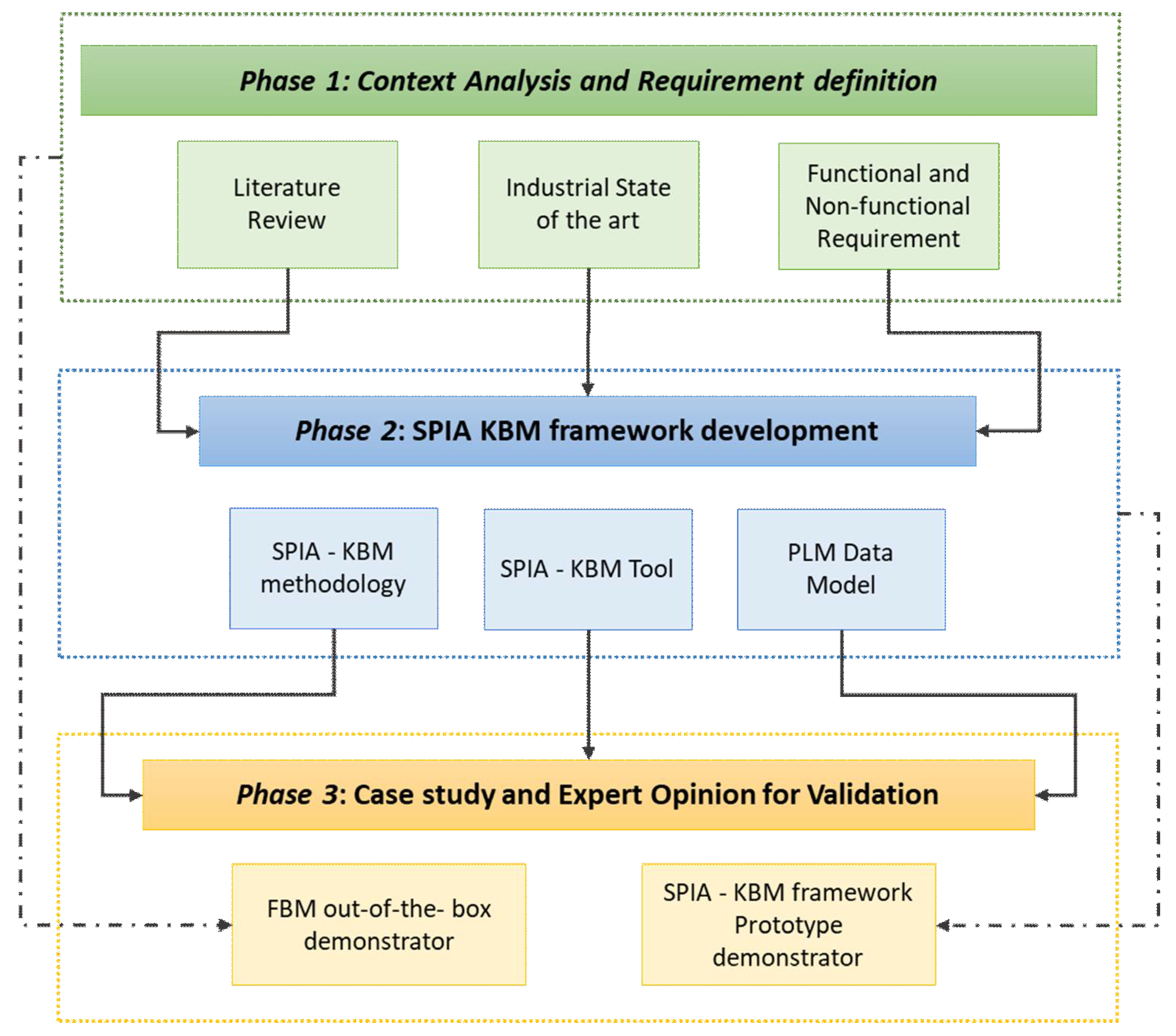
The research methodology employed in this study is presented in
Figure 1.
In phase one, literature was analyzed and the company know-how on design and manufacturing was captured by means of semi-structured interviews; these have been conducted with domain experts as product designer, manufacturing process engineers and CAM operators. A team of University researchers, in collaboration with the industrial partner, analyzed for several months the FBM approach. These analyses included the study of the industrial state of the arts, in terms of actual processes and functionalities provided by Siemens NX FBM module (the CAM tool used by the involved company). The feasibility of using this technology for manufacturing one of company’s products has been evaluated, and the limits of this tool have been analyzed. This preliminary exploration activities allowed the research team to fully understand the complexities of CAM programming automation, to detect open issues in implementing FBM approaches and to define (functional and non-functional) requirements for implementing them in the industrial scenario in an easier and more effective way.
In the second phase of the research study, the framework was formulated: this includes a methodology (Knowledge Based Manufacturing methodology) and a supporting software tool realized to overcome the limits identified. Furthermore, the PLM data model was reviewed and extended. The overall solution was named the SPIA Knowledge-Based Management (SPIA-KBM) framework.
Thanks to the case study implementation, phase three allowed to capture experts’ opinions and to validate the framework identifying strengths and limitations. Interviews and workshops with company staff were used for this purpose. The CAM operator, responsible for the product manufacturing on which the case study focused, actively participated and supported the research team in the implementation of two demonstrators that allowed to compare, in the industrial scenario, the FBM approach with and without the proposed SPIA-KBM framework. The other CAM operators, together with product engineers and manufacturing process engineers, participated in the validation phase.
3.2. Industrial Scenario
Referring to the technological system involved, the industrial case study scenario complies all the prerequisites that are necessary for implementing the proposed solution:
CAD–CAM systems are used as authoring tool for product and manufacturing processes design data;
Machining processes are performed on Numerical Control (NC) machines;
Product lifecycle information are managed by a PLM tool.
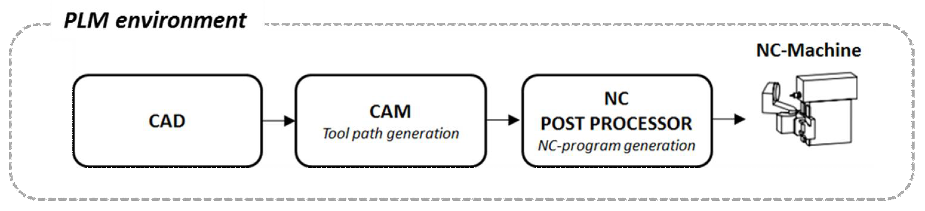
The tool chain adopted in the company is represented in
Figure 2.
The aerospace company uses Siemens NX10 as the CAD–CAM system and Siemens Teamcenter as PLM. However, the use of these specific tools not seems to be a strict requirement. The proposed methodology is conceptual and its implementation could be performed in every company adopting the tool chain described before, and in every CAD–CAM environment, by mean of the right standards for product data transfer (i.e., STEP (Standard for the Exchange of Product) model data).
The engineering and the manufacturing departments work in concurrency and use a PLM system to share data and information. In the product development process, engineering designs the product from the functional and the geometrical point of view, realizing the 3D model and the relative 2D drawing; manufacturing engineers, starting from the 3D model, develop and optimize machining cycles and cutting tools library and create CNC part programs.
The case study has involved turning and milling operations. For both processes, the part CAD model, only containing geometric information, is imported into the CAM environment and enriched with the technological information (e.g., tolerances) needed to obtain the workpiece dimensions and the expected surface quality of the final product. In traditional CAM programming, where tool path are created manually step by step by the operator, after the first activity of workpiece definition, the engineer has to repeat the following steps for each operation to be created: (1) select geometry; (2) select tool; (3) specify cutting and non-cutting parameters; (4) define feeds and speeds; (5) add UDEs (user defined elements); (6) generate the tool path. After creating the different operations, the manufacturing engineer simulate, verify and post process the tool path to obtain the NC-code.
The research project has analyzed the potential of FBM approaches, demonstrating how they can significantly improve productivity, reducing the time needed to create NC programs, reducing the amount of mistakes and supporting the standardization of cutting tools and processes. These improvements are made possible by automating tool paths generation thanks to geometric features recognition and best practices rules application. Recognition of geometric features is done after creation of model in CAD system. Recognition can be made in CAD/CAM systems considering two types of data, i.e., geometrical and topological. This data is stored in specific features libraries. The recognition of features is done by searching and comparing stored information and the model itself [
50].
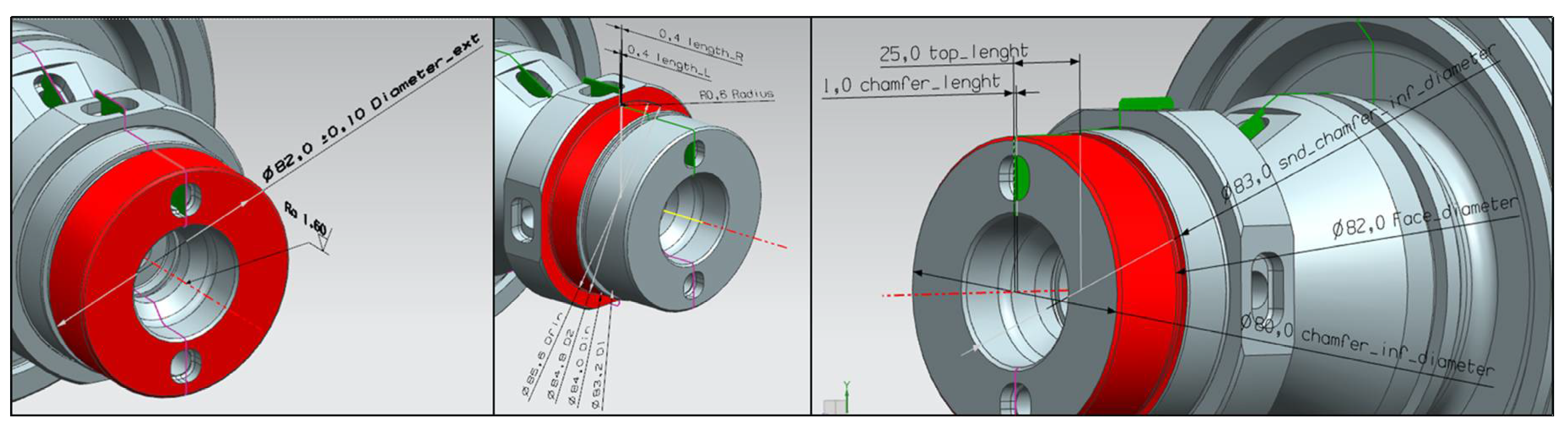
Figure 3 represents a feature and its parameters.
3.3. Requirement Analysis for SPIA-KBM Framework Development
Research activities have been led by the analysis of CAM programming automation complexity characterizing the case study company. Both the rules for machining process creation and the open issues in implementing FBM approaches have been analyzed. These have been translated into requirements of the solution to be developed. Thirty requirements have been defined on turning and milling facing, roughing and finishing operations, regarding: tolerances and roughness, tools choices, materials, machine parameters, etc. As an example, a simplified version of five of such requirements are reported in
Table 1.
The first four expressed requirements reflect the conventions that the CAM operators has to follow, during CNC programming, in defining the tool paths. Sometimes some of these conventions are formalized in company best practices; others are in form of tacit knowledge of the company, closely related to the degree of experience of the personnel.
On the basis of these requirements, manufacturing rules have been defined in the Machining Knowledge Editor (MKE); MKE is a NX stand-alone application where the rule for machining process definition can be edited and saved. Manufacturing engineers with appropriate knowledge and administrative rights can use it to (a) create and modify machining rules libraries; (b) define in-process features; (c) define the alternative processes to be used when the tool required for the preferred process is not available.
The fifth requirement, instead, refers to the need for the CAM operators to customize the defined rules. Indeed, in current industrial environment, machining process are generally developed by CAM specialists that, according to their knowledge and company best practices, define machining processes and implement them in CAM systems to generate the tool path for NC-machines. Current FBM approaches, in which predefined rules are created for toolpath automatic generation, do not consider the possibility, for CAM operator, to modify the pre-determined process. However, in real industrial context, this is something that happens quite often because of different reasons. Among them:
minor differences, between the piece to be worked and the standard one used to create the rules, that allow to apply the generic rules but with some modifications;
unavailability of a specific tool at the moment when the process has to be launched on the NC-machine;
adaptation of some operations to specific machines;
attempts to optimize the cutting strategy.
Nevertheless, using MKE (both to define and edit rules) requires computer and programming skills that CAM operators often do not have. Moreover, in their daily working practice, they need to easily customize the set of parameters within the rules (e.g., feed cut, spindle maximum revolutions per minute, etc.). The standardization required by MKE is therefore too rigorous and not flexible enough for real industrial machining practices, where the expertise of manufacturing engineers is the determiner of tool path quality.
The knowledge synthesized in the rules defined in the FBM tool can be considered as an object associated with the life cycle of the product, in order to ensure information traceability between best practices and manufacturing processes in which they are applied. Based on the need of the company to adopt this strategy an analysis of impacts on the PLM data model has been also necessary. In particular, to solve case study issues, research partners proposed a PLM data model that could allow industrial companies to manage FBM items and trace and document standard rules modifications.
4. Knowledge-Based Manufacturing Framework
From the analysis of current FBM methods, the limits of their application in the industrial scenario and the consequent requirements, as described in the previous section, the ”SPIA Knowledge-Based Manufacturing framework“ (SPIA-KBM) has been formulated and proposed. It is composed by a methodology (KBM Methodology) and a supporting new tool (KBM tool) for data and manufacturing rules management; it allows to transform the current approach defining a data and manufacturing rules management environment, in which knowledge engineers can define the rules, on the basis of industrial best practices, and CAM technologists can customize them for production requirements.
Standard rules made available by FBM modules of out-of-the-box CAM software do not permit to manage exceptions (e.g., unavailability of a specific cutting tool or of a specific CNC machine) that often occur in real industrial scenario, and this make them not fully applicable.
This limitation suggested the design of the proposed methodology and the adjustment of the FBM process: PHASE 2 has been added to facilitate the customization of rules when specific production needs arise.
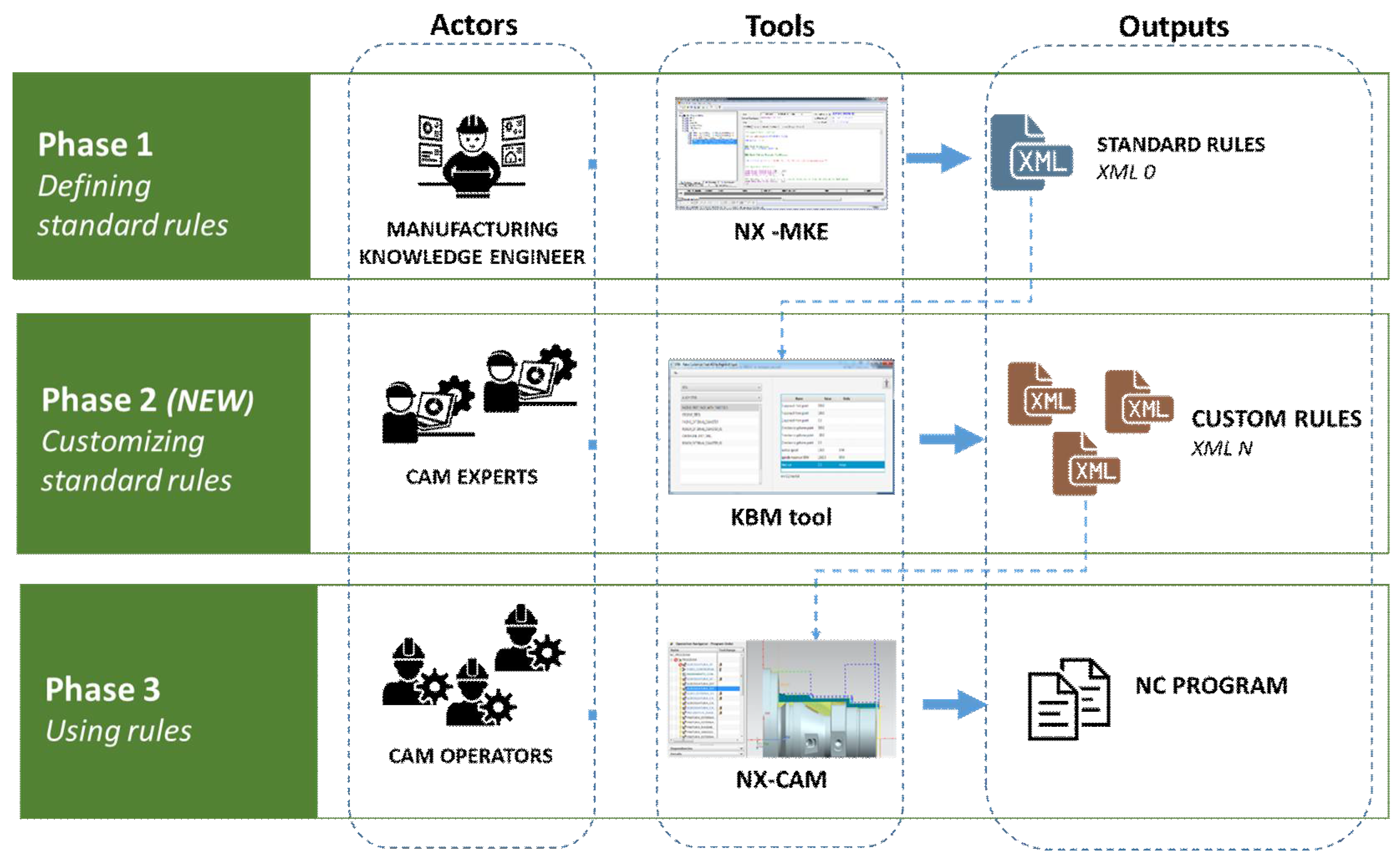
In
Figure 4 the new SPIA-KBM methodology is represented. It consists of three phases.
PHASE 1—Defining standard rules. By means of NX-MKE, the Machining Knowledge Engineer defines machining standard rules, specifying for each of them, the relevant editable parameters (exposed parameters).
PHASE 2—Customizing standard rules. In this phase the CAM Expert can customizes, by mean of the KBM tool, the machining standard rules in order to fit operational needs. The CAM Expert can only edit the value of the exposed parameters.
PHASE 3—Using customized rules. The CAM Operator uses the custom rules, which may be the same as the standard ones if no changes have been made by CAM Expert, to generate the tool path, and subsequently the NC-program, by means of NX-CAM.
The KBM methodology requires to distinguish three roles among the participants in the manufacturing process according to their competences:
Manufacturing Knowledge Engineer: Engineer characterized by a deep expertise in the product and the relative manufacturing processes that has all privileges on the system; he can modify machining rules and develop new ones by mean of NX-MKE. By adding specific comments to the MKE code, he defines which rules parameters can subsequently be changed by the CAM Experts (i.e., exposed parameters). He should have general programming skills even if editing machining and mapping rules does not require knowledge or competences in specific programming language.
CAM Experts: Technologists that can edit the rules defined by Manufacturing Knowledge Engineer entering custom values for the exposed parameters (i.e., speeds, feed rate, tool, starting point of the tool, etc.). In the developed KBM tool, different professional experience levels have been defined: senior technologists (Level 5) can edit all the exposed parameters while other users, with a lower level (level 1 correspond to a new hire), can edit only a part of them.
CAM Operators: They are the final user of the process since they use the custom rules to generate NC program by mean of NX-CAM.
The standard rules, defined by the Manufacturing Knowledge Engineer, are managed in NX through XML files. Any change made by CAM Experts to one of these files (
XML 0 in
Figure 4), using the developed KBM tool, generates new XML files (
XML N in
Figure 4), whose owners are the CAM Experts.
Each standard rule, reported in the XML file, is characterized by a set of information such as the name; operation class and its parameters that determine the motions of the tool during the operation, priority, input and output features (corresponding to the shape of the feature at the beginning and at the end of the operation), the tool typology, application conditions (i.e., tool, operation parameters, tolerance and roughness target, etc.), materials and machines for which the rule is valid, and finally additional information such as cycles, containments, etc.
To implement the KBM methodology, a method to characterize editable parameters has also been created. In NX-MKE [
51], each rule is written through a proprietary programming language for which a line starting with ‘REM’ is considered as remark only and does not have any effect on the behavior of the program. The programmer can use remarks to include short explanations or observations. Remarks have been used to expose editable parameters and to associated them to a minimum CAM expert access level required to access and edit them. These lines are recognized and interpreted by the KBM tool.
Each comment line is composed by the following elements and data types:
Nicename: unique self-explanatory name of the parameter;
User level: minimum user professional level necessary to fix custom parameter value;
Comment: comment string containing useful information for the CAM Experts (optional);
Bounds: boundary values accepted for the parameter (optional);
Unit: unit of measurement (optional);
Value: the standard value of the parameter that can be edited by the CAM Expert.
For instance, the line
REM VAR 1 “feed cut” “min 0.2 max 0.4” “mmpr”
allows the CAM experts, with minimum level 1, to edit the feed rate of the cutter, suggesting, by mean of a comment, that it should vary from a minimum of 0.2 mmpr (millimeters per revolution) to a maximum of 0.4 mmpr.
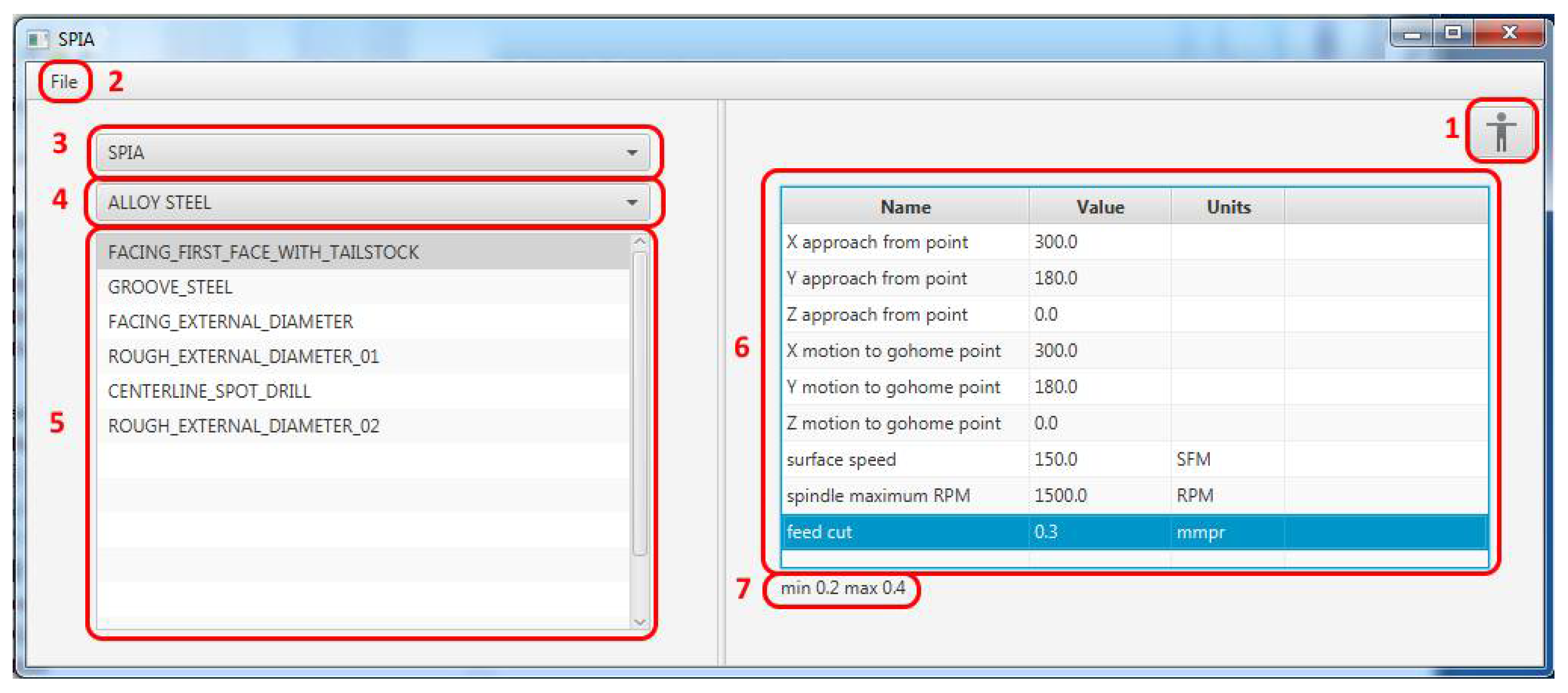
Once editable parameters have been defined by the Manufacturing Knowledge Engineer they are recognized by the tool and exposed to the CAM Expert through the KBM tool user interface represented in
Figure 5.
The CAM Expert login to the system (section 1 in
Figure 5). Then he chooses the XML file to edit (section 2); this can be the standard one or an already customized version of it. Through drop down menus, then he selects the rules sub-set (section 3) and the part material (section 4). All the rules, defined for that material, are shown (section 5).
Selecting a specific rule (e.g., FACING_FIRST_FACE_WITH_TAILSTOCK), the parameters editable, filtered according to CAM Expert professional experience level, are exposed (section 6). For each parameter (e.g., feed cut) a comment is visible in the lower part of the window (section 7) if it has been previously defined by the Manufacturing Knowledge Engineer.
KBM tool allows CAM Experts to customize rules parameters, previously defined by Manufacturing Knowledge Engineers in order to adapt them to specific operating conditions and needs (i.e., necessity to adopt a different tool, to adapt the operation to specific machines, etc.). Furthermore, the tool allows to set specific geometrical parameters (like containment) that cannot be automatically interpreted by the CAM software because they do not belong to the final feature.
The main focus in the KBM tool design and development was to provide a tool extremely easy to use and able to show, to technologists, only the strictly necessary information. Through the tool, it is possible to read the rules from NX-MKE, edit them according to specific conditions and needs and return the updated rules to NX-CAM. This tool is very easy to use and install, and has been developed to communicate, in input, with NX-MKE, in order to read the defined rules, and in output with NX-CAM, in order to send customized rules, defined by technologist. It allows user profile management and allows different users to save different customized rules. In the next release, it will contain check on customized parameters.
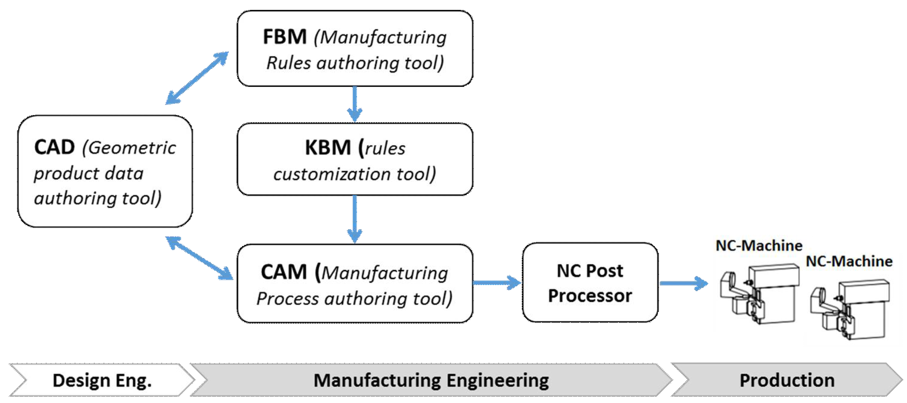
The proposed methodology is applicable in a generic industrial scenario, with similar characteristics of the case study’s one but with different IT systems. Those involved in the proposed methodology, and reported in
Figure 6, are:
CAD system as product data authoring tool;
FBM as manufacturing rules authoring tool;
KBM tool as rules customization tool. In this research the tool that has been developed for Siemens NX;
CAM system as manufacturing processes authoring tool.
Nevertheless, even if most of commercial software are supposed to be compliant with the proposed KBM methodology, further researches are necessary to investigate the interoperability between the different systems involved.
The tool has been developed and tested in close cooperation with company engineers and technologists. The test in the industrial scenario has shown quantitative benefits in terms of time and cost savings, both depending on product complexity: greater complexity leads to greater benefits. During the testing phase, the measured times and costs were comparable to those obtained without the application of the KBM framework due to the need to create the rules database from scratch. When the framework is fully operational (upon completion of the rules database) cost and time savings will be maximized.
Also, qualitative benefits emerged in terms of the degree of standardization obtainable and codification and reuse of the tacit knowledge of experienced engineers.
5. Impacts on PLM Data Model Revision
A PLM model defines and structures the information concerning a product during its entire lifecycle and through the extended enterprise [
11]. Defining the data model is the first step in many PLM implementations. The ability to model engineering and manufacturing data as well as processes is very important; in many cases, information modeling and process formalization are the main difficulties, but they set the success of the PLM system implementation [
11,
52]. Since the topic of modeling is about company products and processes, it is always coming as something unique in the organization. In the past, systems were not flexible and required physical change (re-build) to handle specific product and process data. Nowadays, product data/lifecycle management (PDM/PLM) systems offer flexible data modeling capabilities and enable customers to adapt them to specific needs and situation. However, the cost of this adaption is sometimes very expensive [
53].
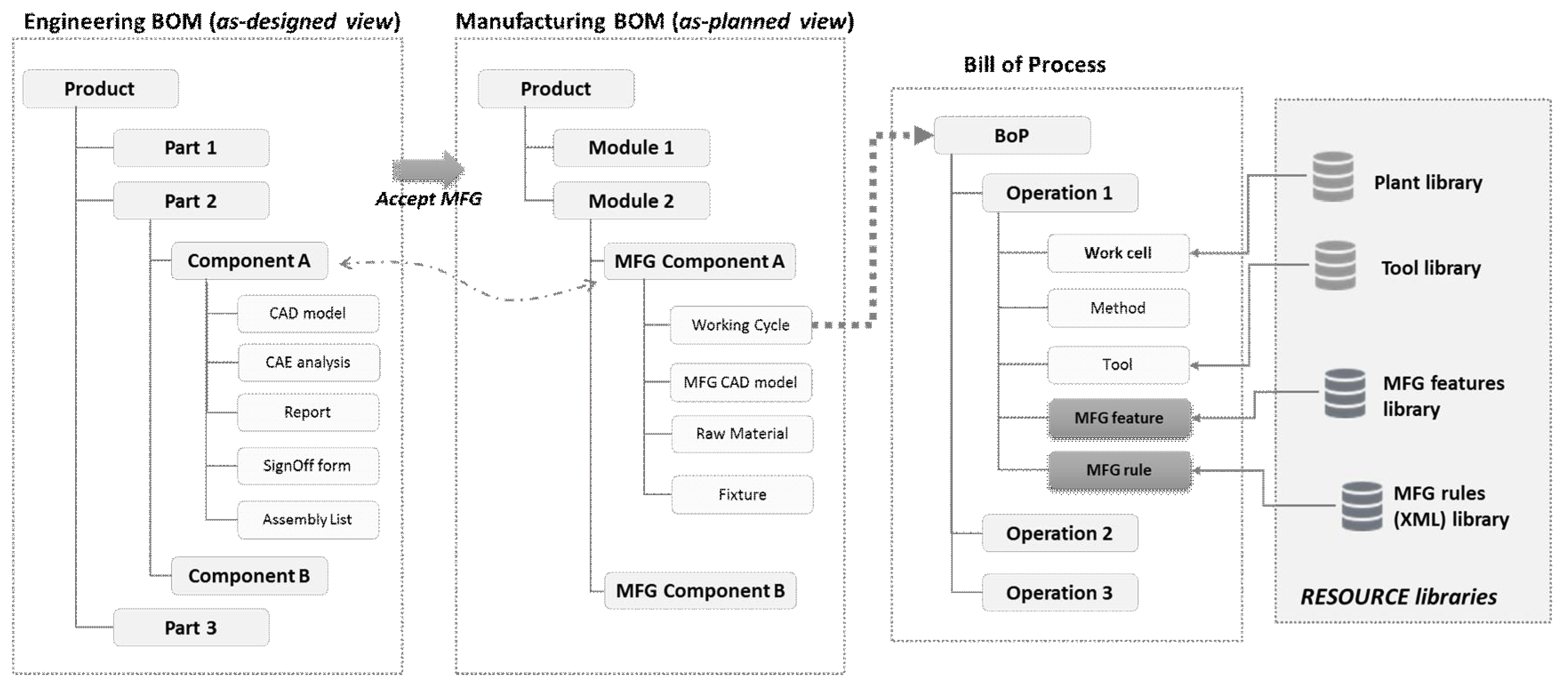
Figure 7 shows the impacts of the FBM methodology on a generic PLM data model. It refers only to the middle stages of the product life cycle:
as-designed and
as-manufactured (also named
as-planned) views that respectively correspond to engineering and manufacturing BOMs (Bill of Material).
The As-designed view reflects the way a product is functionally designed. During product development engineers can design (or reuse) assemblies (parts) and add new components and assemblies to the design. The As-designed view is used for product certification and approval, and it must therefore be maintained congruent with other views (i.e., as-built and as-maintained). It is composed by engineering items structured hierarchically and it is configurable for effectiveness. The main elements of the engineering product structure are CAD models that represent every part from the geometric point of view, CAE analysis results and report, and sign-off forms resulting from approval workflows.
The As-planned view drives manufacturing planning activities and reflects the way a product and its parts will be fabricated, assembled, and installed. It is therefore the reference configuration for production scheduling and plant and manufacturing facilities management. The parts accepted in the engineering view can be reorganized into independent structures. The main changes from engineering bill of materials (EBOM) to manufacturing bill of materials (MBOM) are for example the removal of components that do not exist in the physical world, e.g., a grouping of two sub-assemblies which are logically grouped by the designer, but as a group do not make sense for manufacturing, and in the addition of non-design items which are instead needed for manufacturing the product. Manufacturing engineers also add information in MBOM related to fixtures, tooling, raw materials, or semi-finished products.
NC programming is created from the CAD geometry information of part in MBOM. BoP (Bill of Process) is the detailed operations sequence to produce a given part or product. It is created in MBOM context and BOM component can be related to one or more operation in BoP. The BoP defines the resources needed, the operation to be performed with these resources and the sequence of operations to create the desired part. An operation defines a material removal action, containing all the information needed to generate tool paths for the operation. Cutting tool information and basic machining parameters are specified.
Adopting the KBM methodology enables to extend the above described PLM data structure. Two new items can be considered related to operations: the manufacturing features (created by the Manufacturing Knowledge Engineer) to which the operation refers and the manufacturing rule item, related to the specific XML file modified by CAM Expert and used to automatically determine, based on organizational knowledge, machining methods and parameters, cutting tools, etc. Moreover, this enables to ensure information traceability between best practices and manufacturing processes in which they are applied.
PLM systems involve libraries that enable to store and retrieve data about resources (e.g., tools, fixtures, machinery, and process templates) from a common database accessible to the entire organization. In addition to the plant and tools libraries already existing, libraries for the management of feature and rules XML files need to be managed. As all items managed in the PLM data model, the proposed new ones need to be subjected to specific approval and review processes.
6. Conclusions
The aim of the research activity has been to define a Knowledge Based Manufacturing Framework, implementing and testing a methodology and a supporting tool that could improve the management and customization of machining rules. To integrate it with the Product Lifecycle Management environment, the impacts of the proposed methodology on the PLM data model have been analyzed.
An action research approach has been followed by authors: the industrial case study and the collaboration among academic and industrial teams have played a central role in the study. It has been led by the concrete need to develop a solution for a concrete industrial problem.
The achieved results do not propose a revision of the company modus operandi; rather, they offer methods and tools to support engineers and technologists, facilitating and speeding up their daily operations. The industrial actors who contributed in defining machining rules and their customization are compatible with professionals of the industrial partner as well as the proposed new operating process is compatible with existing procedures.
The main benefits achieved by the research are the reduction of complexity in adopting FBM tools, and the overcoming of some of their limitations. In particular, the ability to customize machining rules parameters fostered the use, within the involved industrial company, of Feature Based Manufacturing approaches.
Even if the research has been conducted in a NX-centered scenario, the proposed methodology, which is general for each manufacturing industry facing FBM problems, could be implemented in every company adopting a CAD–CAM–CNC tools chain, if necessary using standards for product data exchange.
The generalization of the SPIA-KBM, however, requires further research to be able to propose a complete set of procedure that are platform-independent and detailed for each possible use case. Referring to the tool, in a future release, a new function for checking the customized parameters will be introduced.
With the proposed methodology, the structured manufacturing rules become an item of knowledge to be handled along all the product life cycle. For such a reason, manufacturing features need to be managed in PLM libraries. The best strategy is to create a model for each feature, adding product and manufacturing information (PMI) and archiving model in the PLM in order to be able to retrieve it and the related knowledge.
The assessment of these impacts was built based on the experiences of the partners involved in the project and requires further analysis and insights: e.g., considering the relationship between the model with what has been presented by international standards (such as STEP, International Organization for Standardization—ISO, etc.). Moreover, the data model implementation in a PLM system needs to be tested and defined from a technological point of view.


