Axial Ratio and Gain Enhancement of a Circular-Ring Slot Antenna Using a Pair of Asymmetrical Rectangular Slots and a Parasitic Patch for a Radio Beacon on a Nanosatellite

 and
and
Abstract
:1. Introduction
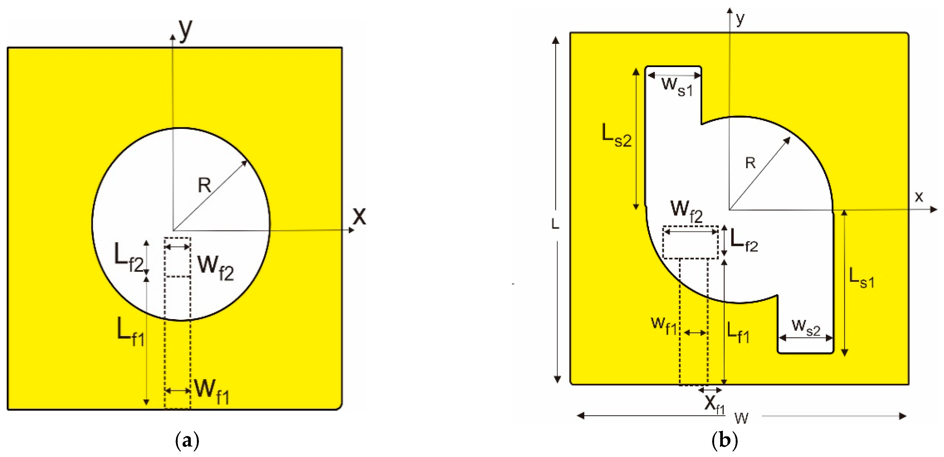
2. Circular-Slotted Antenna
3. A Pair of Rectangular Slots and Parasitic Patch for the 3 dB ARBW and the Gain Enhancement
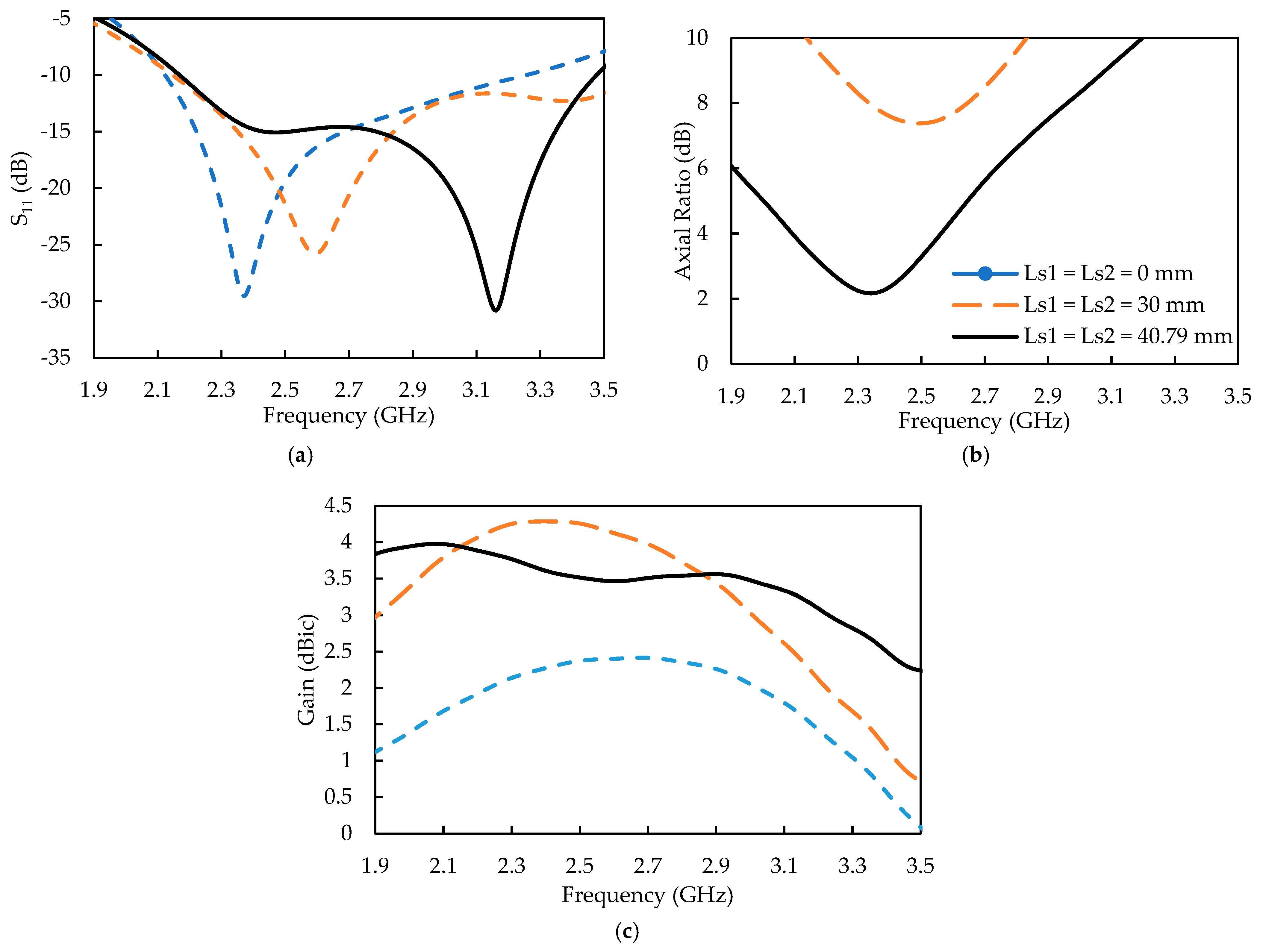
3.1. A Pair of Symmetrical Rectangle Slots (Model 1)
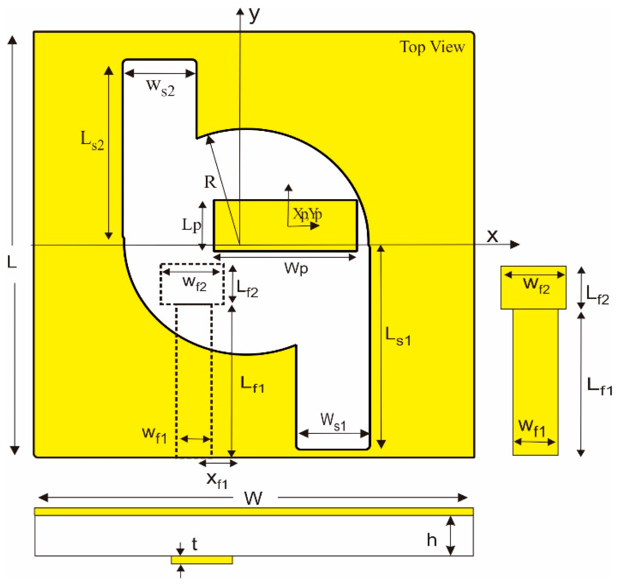
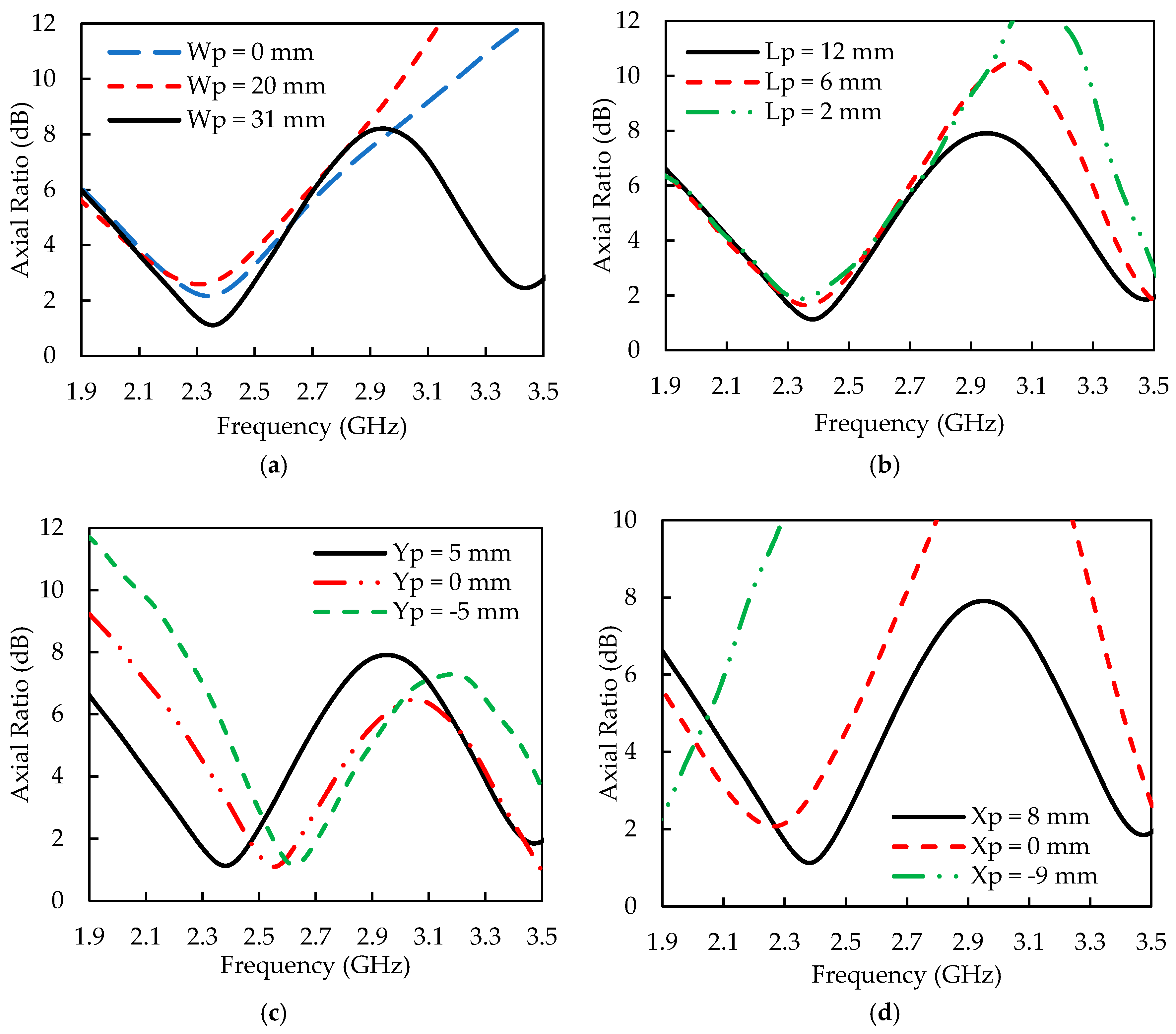
3.2. A Rectangular Parasitic Patch (Model 2)
4. Results and Discussion
5. Conclusions
Author Contributions
Funding
Acknowledgments
Conflicts of Interest
References
- Sri Sumantyo, J.T.; Imura, N. Development of GNSS-RO and EDTP sensors onboard microsatellite for Ionosphere monitoring. In Proceedings of the 2015 IEEE International Geoscience and Remote Sensing Symposium (IGARSS), Milan, Italy, 26–31 July 2015. [Google Scholar]
- Sri Sumantyo, J.T. Development of Microsatellites for Atmospheric and Land Deformation Observation. In Proceedings of the Asia Oceania Geoscience Symposium (AOGS), Hokkaido, Japan, 28 July–1 August 2014; p. 219. [Google Scholar]
- Nugent, R.; Munakata, R.; Chin, A.; Coelho, R.; Puig-Suari, J. The cubesat: The picosatellite standard for research and education. Aerosp. Eng. 2008, 805, 756–5087. [Google Scholar]
- Pansomboon, R.; Phongcharoenpanich, C.; Phudpong, R. Design of a Dual-Band Quadrifilar Helical Antenna for Radio Beacon Receiver. In Proceedings of the 2011 International Symposium on Intelligent Signal Processing and Communications Systems (ISPACS), Chiang Mai, Thailand, 7–9 December 2011. [Google Scholar]
- Bernhardt, P.A.; Siefring, C.L. New satellite-based systems for ionospheric tomography and scintillation region imaging. Radio Sci. 2006, 41. [Google Scholar] [CrossRef]
- Sze, J.Y.; Hsu, C.-I.G.; Chen, Z.-W.; Chang, C.-C. Broadband CPW-fed circularly polarized square slot antenna with lightening-shaped feed-line and inverted-L grounded strips. IEEE Trans. Antennas Propag. 2010, 58, 973–977. [Google Scholar] [CrossRef]
- Chen, Z.-N.; Qing, X. Symmetric-aperture antenna for broadband circular polarization. IEEE Trans. Antennas Propag. 2011, 59, 3932–3936. [Google Scholar]
- Row, J.S. The design of a squarer-ring slot antenna for circular polarization. IEEE Trans. Antennas Propag. 2005, 53, 1967–1972. [Google Scholar] [CrossRef]
- Wong, K.L.; Wu, J.Y.; Wu, C.K. A circular-polarized patch loaded square slot antenna. Microw. Opt. Technol. Lett. 1999, 23, 363–365. [Google Scholar] [CrossRef]
- Tseng, L.Y.; Han, T.Y. Microstrip-fed circular slot antenna for circular polarization. Microw. Opt. Technol. Lett. 2008, 50, 1056–1058. [Google Scholar] [CrossRef]
- Xu, Z.; Liu, J.; Huang, S.; Li, Y. Gain-enhanced SIW cavity-backed slot antenna by using TE410 mode resonance. Int. J. Electron. Commun. 2019, 98, 68–73. [Google Scholar] [CrossRef]
- Wong, K.L.; Huang, C.C.; Chen, W.S. Printed ring slot antenna for circular polarization. IEEE Trans. Antennas Propag. 2002, 50, 75–77. [Google Scholar] [CrossRef]
- Sze, J.Y.; Chen, W.H. Axial-ratio-bandwidth enhancement of a microstrip-line-fed circularly polarized annular-ring slot antenna. IEEE Trans. Antennas Propag. 2011, 59, 2450–2456. [Google Scholar] [CrossRef]
- Qing, X.M.; Chia, Y.W.M. Circularly polarized circular ring slot antenna fed by stripline hybrid coupler. Electron. Lett. 1999, 35, 2154–2155. [Google Scholar] [CrossRef]
- Zhang, J.L.; Yang, X.Q. Integrated compact circular polarization annular ring slot antenna design for RFID reader. Prog. Electromagn. Res. Lett. 2013, 39, 133–140. [Google Scholar] [CrossRef]
- Chang, T.N.; Lin, J.M. Circularly polarized antenna having two linked slot-rings. IEEE Trans. Antennas Propag. 2011, 59, 3057–3060. [Google Scholar] [CrossRef]
- Aziz, M.Z.A.A.; Mufit, N.A.D.A.; Rahim, M.K.A.; Kamaruddin, M.R. Design X-circular polarized with slant rectangular slot by using single port. In Proceedings of the 2012 International Symposium on Antennas and Propagation, Nagoys, Japan, 29 October–2 November 2012; pp. 555–558. [Google Scholar]
- Lu, H.J.; Tang, C.L.; Wong, K.L. Single-feed slotted equilateral-triangular microstrip antenna for circular polarization. IEEE Trans. Antennas Propag. 1999, 47, 1174–1178. [Google Scholar]
- Ellis, M.S.; Zhao, Z.; Wu, J.; Ding, X.; Nie, Z.; Liu, Q. A novel simple and compact microstrip-fed circularly polarized wide slot antenna with wide axial ratio bandwidth for C-Band applications. IEEE Trans. Antennas Propag. 2016, 64, 1552–1555. [Google Scholar] [CrossRef]
- Sung, Y. Bandwidth enhancement of a microstrip line-fed printed wide-slot antenna with a parasitic center patch. IEEE Trans. Antennas Propag. 2012, 60, 1712–1716. [Google Scholar] [CrossRef]
- Fu, S.; Kong, Q.; Fang, S.; Wang, Z. Broadband Circularly Polarized Microstrip Antenna with Coplanar Parasitic Ring Slot Patch for L-Band Satellite System Application. IEEE Antennas Wirel. Propag. Lett. 2014, 13, 943–946. [Google Scholar]


| Models | (mm) | (mm) | (mm) | (mm) | (mm) | (mm) | (mm) | (mm) | (mm) | (mm) |
|---|---|---|---|---|---|---|---|---|---|---|
| Conventional | 26.5 | - | - | 4 | 4 | 0 | - | - | - | - |
| Model 1 | 26.5 | 40.79 | 40.79 | 4 | 4 | −9 | - | - | - | - |
| Model 2 | 26.5 | 48 | 40 | 4 | 10 | −9 | 12 | 31 | 8 | 5 |
| Model | (GHz) | Impedance Bandwidth IBW (GHz), % | (GHz) | 3 dB ARBW (GHz), % | Gain (dBic) |
|---|---|---|---|---|---|
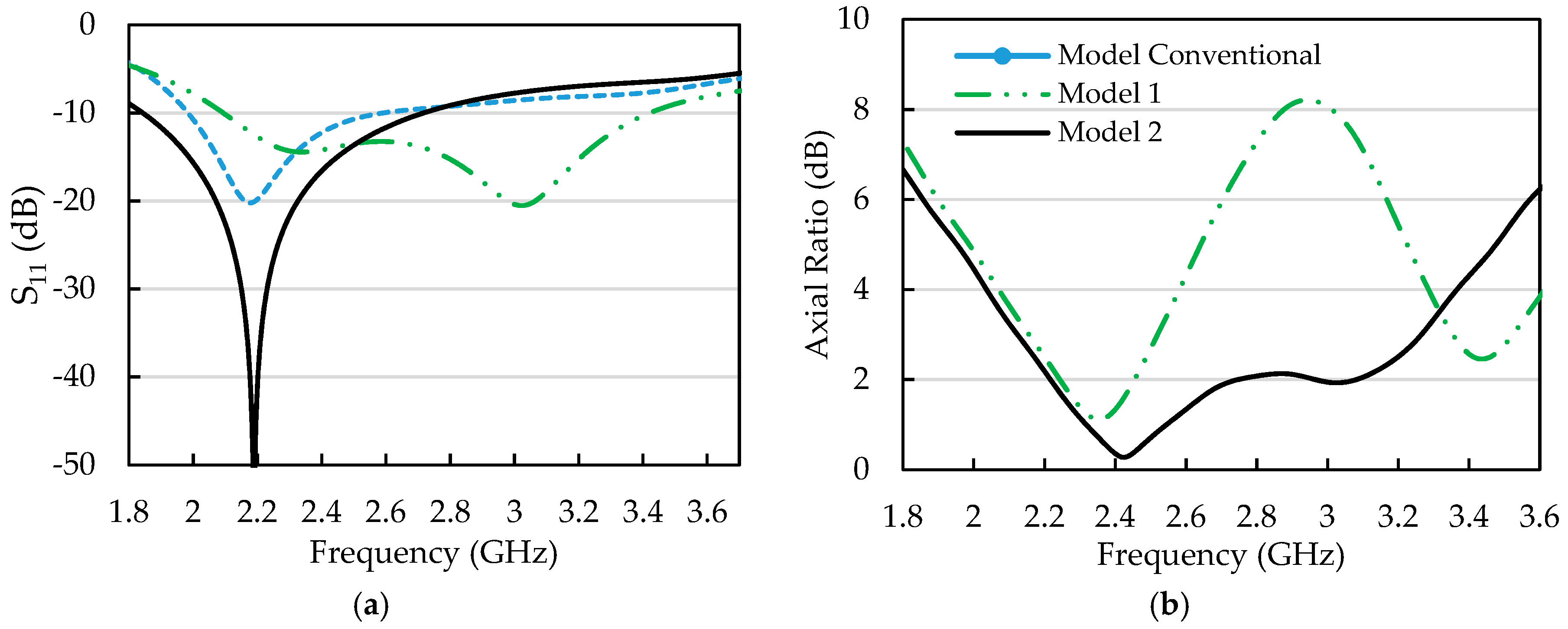
| Conventional | 2.17 | 1.98–2.58 (27.26%) | - | - | 1.85 |
| Model 1 | 3.02 | 2.10–3.41 (43.43%) | 2.36 | 2.16–2.52 (15.25%) | 3.65 |
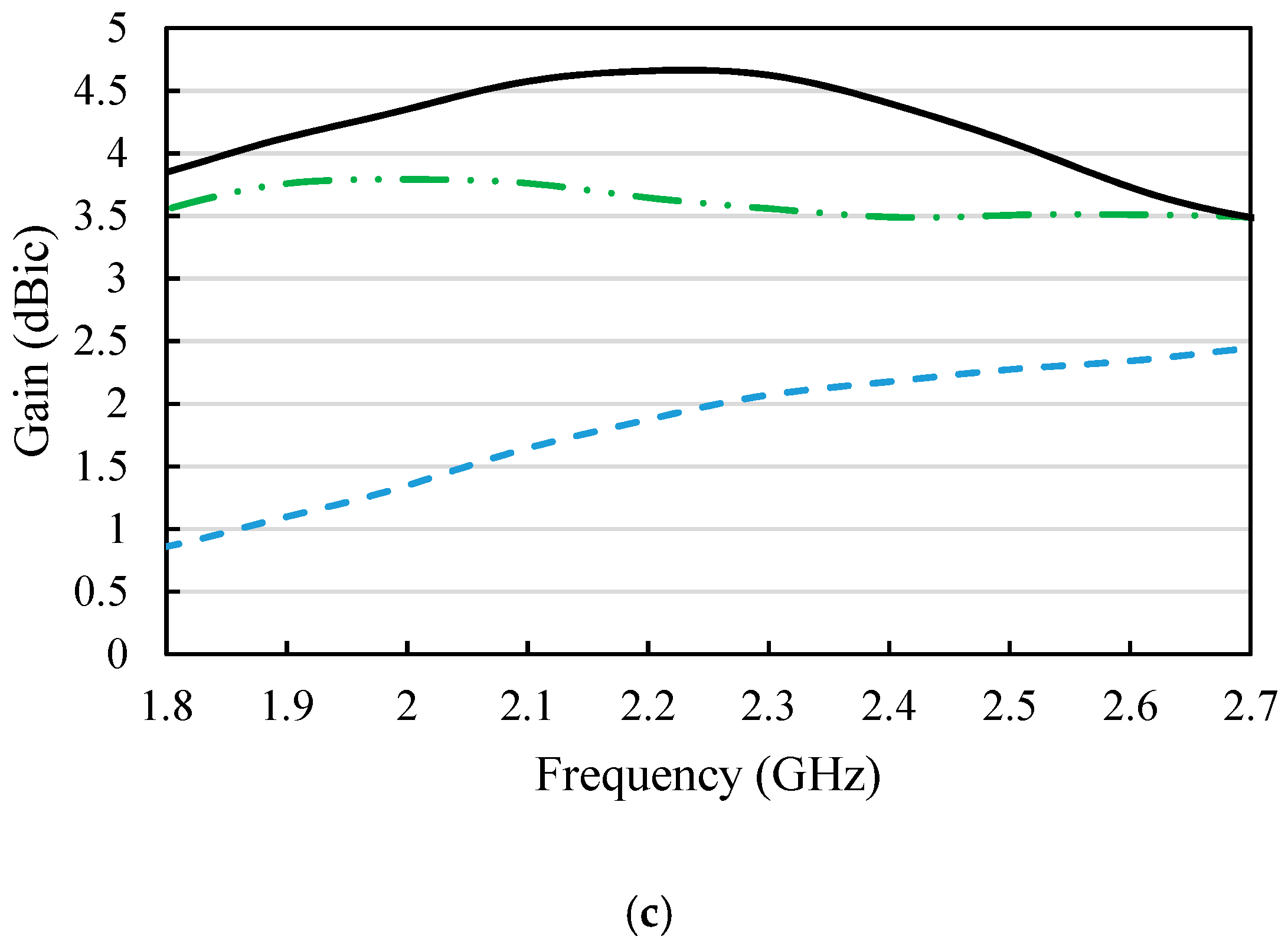
| Model 2 | 2.18 | 1.84–2.71 (39.62%) | 2.42 | 2.13–3.26 (46.69%) | 4.66 |
| Reference | 3 dB Axial Ratio Bandwidth (ARBW) (%) | Impedance Bandwidth (IBW) (%) | Peak Gain (dBic) | Dimension (mm) | |
|---|---|---|---|---|---|
| [6] | 2745 | 48 | 51 | 4.2 | 60 × 60 × 0.8 |
| [7] | 3625 | 68 | 107 | 4 | 60 × 60 × 1.6 |
| [8] | 1590 | 6.3 | 14.7 | 3.6 | 54 × 54 × 1.6 |
| [10] | 2375 | 12 | 39 | 5.5 | 120 × 120 × 33 |
| Proposed | 2200 | 35.79 | 47.27 | 5 | 95 × 100 × 1.6 |
© 2019 by the authors. Licensee MDPI, Basel, Switzerland. This article is an open access article distributed under the terms and conditions of the Creative Commons Attribution (CC BY) license (http://creativecommons.org/licenses/by/4.0/).
Share and Cite
Sitompul, P.P.; Sri Sumantyo, J.T.; Kurniawan, F.; Nasucha, M. Axial Ratio and Gain Enhancement of a Circular-Ring Slot Antenna Using a Pair of Asymmetrical Rectangular Slots and a Parasitic Patch for a Radio Beacon on a Nanosatellite. Aerospace 2019, 6, 39. https://doi.org/10.3390/aerospace6040039
Sitompul PP, Sri Sumantyo JT, Kurniawan F, Nasucha M. Axial Ratio and Gain Enhancement of a Circular-Ring Slot Antenna Using a Pair of Asymmetrical Rectangular Slots and a Parasitic Patch for a Radio Beacon on a Nanosatellite. Aerospace. 2019; 6(4):39. https://doi.org/10.3390/aerospace6040039
Chicago/Turabian StyleSitompul, Peberlin Parulian, Josaphat Tetuko Sri Sumantyo, Farohaji Kurniawan, and Mohammad Nasucha. 2019. "Axial Ratio and Gain Enhancement of a Circular-Ring Slot Antenna Using a Pair of Asymmetrical Rectangular Slots and a Parasitic Patch for a Radio Beacon on a Nanosatellite" Aerospace 6, no. 4: 39. https://doi.org/10.3390/aerospace6040039