Article

Static and Dynamic Performance of a Morphing Trailing Edge Concept with High-Damping Elastomeric Skin

1
Department of Industrial Engineering—Aerospace Division, University of Naples “Federico II”, Via Claudio, 21, 80125 Napoli (NA), Italy
2
Fraunhofer Institute for Manufacturing Technology and Advanced Materials, Wiener Straße 12, D-28359 Bremen, Germany
3
Smart Structures Division Via Maiorise, The Italian Aerospace Research Centre, CIRA, 81043 Capua (CE), Italy
*
Authors to whom correspondence should be addressed.
Aerospace 2019, 6(2), 22; https://doi.org/10.3390/aerospace6020022
Submission received: 18 November 2018 / Revised: 7 February 2019 / Accepted: 14 February 2019 / Published: 19 February 2019
(This article belongs to the Special Issue Adaptive/Smart Structures and Multifunctional Materials in Aerospace)

Abstract

:
Nature has many striking examples of adaptive structures: the emulation of birds’ flight is the true challenge of a morphing wing. The integration of increasingly innovative technologies, such as reliable kinematic mechanisms, embedded servo-actuation and smart materials systems, enables us to realize new structural systems fully compatible with the more and more stringent airworthiness requirements. In this paper, the authors describe the characterization of an adaptive structure, representative of a wing trailing edge, consisting of a finger-like rib mechanism with a highly deformable skin, which comprises both soft and stiff parts. The morphing skin is able to follow the trailing edge movement under repeated cycles, while being stiff enough to preserve its shape under aerodynamic loads and adequately pliable to minimize the actuation power required for morphing. In order to properly characterize the system, a mock-up was manufactured whose structural properties, in particular the ability to carry out loads, were also guaranteed by the elastic skin. A numerical sensitivity analysis with respect to the mechanical properties of the multi-segment skin was performed to investigate their influence on the modal response of the whole system. Experimental dynamic tests were then carried out and the obtained results were critically analysed to prove the adequacy of the adopted design approaches as well as to quantify the dissipative (high-damping) effects induced by the rubber foam on the dynamic response of the morphing architecture.

1. Introduction

Over the next few years, a new generation of air vehicles characterized by high aerodynamic efficiency and low environmental impact could dramatically contribute to achieving the objectives set by the Advisory Council for Aviation Research and Innovation in Europe (ACARE), such as greening and noise reduction. Next-generation aircraft require wings able to reconfigure themselves in multiple shapes in order to match specific flight conditions and reduce fuel waste resulting from non-optimal flight dynamics. Aircraft wings capable of such in-flight reconfiguration are referred to as morphing wings [1,2].
One of the key challenges to developing a successful morphing wing is the development of a flexible skin, a continuous layer of material that stretches over a stiff structure, preserving a smooth external surface. Compliant structures are designed to achieve large deformations by relying upon elastic straining of their inner elements. This property would require a high load-carrying capability to sustain aerodynamic pressures, and sufficient flexibility to implement target shapes by the actuation system under the concurrent action of the same external forces. In [3], the authors discuss how compliant deformation and stiffness concepts, albeit contrasting, are important for a morphing structure. Such a study, carried out about 10 years ago, showed that both the structural and material concepts found in the literature at that time did not fulfil all those characteristics. In other words, the level of maturity of morphing skins was still low and the proposed concepts were still unclear. Indeed, combining adequate flexibility and stiffness concepts into a single skeleton is a real design challenge. Kinematic architecture, made of rigid bodies connected to each other, should nevertheless rely on a skin that envelops the skeleton and guarantees the preservation of a regular geometry during shape change. A significant tendency in implementing adaptive surfaces in the rotorcraft field is also taking place. Investigations into the potential of Continuous Trailing-Edge Flaps (CTEF) for enhanced helicopter primary flight control were described in [4]. The CTEF idea encompassed airfoil-embedded active materials to deform the trailing edge section in a static or dynamic way while keeping the target geometry. Solutions to overcome those issues, with a particular focus on the state of the art of morphing technologies for rotor blades, were instead reported in [5].
Over the years, different solutions have been proposed to create smooth surfaces for morphing wings. Anisotropy is essential for corrugated laminates’ suitability. A structure combining a corrugated skin and a honeycomb-reinforced elastomer was suggested in [6]. The skin could stretch and resist vertical aerodynamic loads thanks to differential behaviour along the in-plane and normal directions. Elastomeric-coated composite corrugated panels were proposed in [7], addressing shape optimization for an augmented performance of the morphing skin, even considering manufacturing constraints. A similar concept was reported in [8], where structural elements with in-plane tuneable stiffness were introduced. The design of composite skins with silicone rubber matrix and CFRP rods reinforced by Kevlar layers was studied in [9]; the prototype could attain ±30° pure shear morphing. In [10], an Adaptive Aspect Ratio (AdAR) wing was presented, coupling a compliant skin (the dominant component) with a kinematic internal structure consisting of sliding ribs over a telescopic main spar, to create a morphing aerodynamic surface capable of significant changes in span and aspect ratio. Again, it was necessary to balance in-plane and out-of-plane stiffness. In [11], a further camber morphing concept (FishBAC) was introduced. The effects of such a technology on a straight, rectangular wing architecture were discussed with reference to a 25-kg UAV (speed range, weight penalties, max allowable span retraction, and so on). Camber morphing appeared to favour larger weight configurations at high speeds, while combination of camber with span morphing provided the largest aerodynamic efficiency improvements for missions with both low and high-speed phases. In [12], a skin technology based on a combination of an elastomeric outer skin, a flexible honeycomb, and a fiberglass laminate was presented to realize a hybrid morphing trailing edge control surface of a UAV, also addressing camber variation.
Currently, many activities aim at implementing “intelligent” performance inside the skin—for instance, in order to measure the deformation state or to monitor structural conditions. In [13], one of the first works on this topic, a distributed sensor system developed at NASA Langley Research Center was placed on a morphing wing surface to collect strain field information. Deformation map was first reduced into a distribution of local slopes over a flat surface under the hypothesis of linearity; then, the morphed curved surface could be approximated by a collection of individual flat surfaces of different slope and used as a reference for an active shape control system. Feasibility studies to realize a carbon nanotubes-based strain sensor system were described in [14,15]. In [16], the authors presented a 3D shape sensing of flexible morphing wing using arrays of Fiber Bragg Grating (FBG) sensors. The maximum error between 3D-visual and FBG measurements was proven to be less than 5%, and the proposed method was effective for deformed surface reconstruction. In [17], embedded sensors were introduced to measure the surrounding flow and give a reference to control the actuators’ action. Therein, it was also demonstrated that significant power consumption reductions were possible by exploiting inherent hysteretic properties of SMA and appropriately tailoring the control strategy. In [18], conceptual design and modelling of a distributed sensor system based once more on FBG was reported, aimed at measuring span-wise and chord-wise variations of an adaptive trailing edge. The sensor system was made of two integrated technological solutions for detecting spanwise and chord-wise strains, forming a closed grid network that revealed the complete deformed shape.
An extensive review of actuation morphing concepts, applied to unmanned aircraft, may be found in [19]. In the already mentioned kinematic morphing (rigid body architectures), distributed electromechanical actuation have shown significant advantages compared to conventional shafted arrangements, due to their ability to move individual components either synchronously or independently. In [20], a quick-return mechanism for chord-wise camber variations was reported. Motion was transmitted from servo-rotary actuators to adaptive trailing edge device elements. Both inherent rotation sensors associated to each actuator (encoders) and an FBG-based distributed sensor network were used to synchronize the different movements. However, although such a mechanism showed high accuracy and compactness, the potential failure ratio increased because of the larger number of requested motors to withstand external aerodynamic loads. Design, simulation, and control of a miniature linear actuator for morphing wing actuation was proposed in [21]. In that case, the actuator consisted of a miniature brushless direct current (BLDC) motor, a gearing system, and a trapezoidal screw, and was verified as of to managing the high force field appearing under the morphing skin during wind tunnel tests. A wide discussion of the main features of shape memory alloys (SMA) for compliant morphing aircraft was reported in [22]. Particular emphasis was given to camber and twist motions, while the system design tried to maximize the actuation bandwidth and minimize the power consumption. Along the same line, the effectiveness of an SMA thin film actuator to modify an airfoil shape for performance improvement was presented in [23]. Lately, the scientific and technological community is showing growing interest in bi-stable morphing concepts, thanks to the expected benefit of reducing the complexity of servo-activated control systems [24,25].
Studies of morphing control systems have been often referred to as UAV, particularly micro air vehicles (MAV). In [26], the authors worked on the aerodynamic shape optimization to obtain basic wing geometrical properties that would have allowed maximum range and endurance. A detailed study of MAV design is reported in [27]. A design framework was introduced for enhancing roll control authority through morphing wing deployments for non-symmetric twist distribution. A co-simulation strategy for modelling unsteady dynamics of biologically-inspired flapping-wing MAV was developed and reported in [28]. Preliminary control pulse flight-test campaigns were completed for a prototype gull-wing morphing aircraft and described in [29]. The investigated vehicle demonstrated augmented longitudinal and lateral dynamic stability performance. In [30], the same authors proved the lateral dynamics control authority improvement by morphing wings.
The present paper deals with an innovative structural concept development, tested on a two-bay trailing edge segment that was made of three articulated finger-like ribs and covered by a multi-material hyper-elastic skin. The goal was to understand and evaluate how morphing skin could affect the adaptive structural system dynamic response, with particular reference to damping increase and modal characteristics’ deviation. Both aspects are essential for aeroelastic assessment, because an augmented DOF system has a reasonably higher modal density than a usual one, leading to more critical behaviour. It should be properly considered that an elastomeric morphing skin has important mass and stiffness contributions. For typical materials, skin may attain almost 30–40% of the global weight, while normal chord-wise stiffness should be in the range of about 10% with respect to the overall value. Skin-added bending rigidity can be neglected with respect to the basic overall structural one, both spanwise and chord-wise. As far as the authors know, the presented analyses are not common in the literature, with some minor exceptions [31]. Moving from those preliminary results, this research aims at drafting another step for assessing a methodology for defining morphing structure properties and, particularly, morphing skin specs. This work was carried out within the framework of SARISTU (Smart Intelligent Aircraft Structures), an EU FP7 project that ended in 2015. It involved the design and integration of a full-scale morphing wing section including multiple adaptive structural devices: a droop nose, a morphing winglet and an adaptive trailing edge, designed on a new-generation jet aircraft specifications. Prior the ultimate system manufacture, the authors focused on a dummy, a 2-bay segment of the final 5-bay ATED demonstrator (Figure 1) [32].

2. Summary and Investigation Strategy

The load-bearing capability of a morphing trailing edge, as well as its ability to reproduce target shapes under the action of aerodynamic and inertial loads, was already discussed in previous works [33,34]. Similar investigations of a more conventional and segmented skin suitable for a morphing aileron were detailed in [35]. Numerical simulations by finite element analysis were elaborated to support these investigations; numerical models’ reliability as well as the overall structural concept functionality and performances were finally proven through experimental tests on a full-scale test article. In this work, the influence of the mechanical properties of a multi-component skin on the modal response of a morphing trailing edge was investigated. Trade-off analyses were carried out to assess the change in the most relevant natural frequencies upon the variation of the elastic properties of the multi-material skin. Most of the issues related to the skin integration, such as temperature and environmental effects, fatigue and chemical resistance, were investigated with reference to the stand-alone skin specimen. Moreover, vibration tests on a two-bay test article proved the amount of damping measured on the single sample of elastomeric material. These dynamic tests made it possible to highlight the damping effect of the highly deformable foam-based skin, potentially leading to improved wing aeroelastic stability. The trailing edge was in fact designed for the outboard sections of both wings, which are usually very sensitive to vibratory phenomena and prone to aeroelastic instabilities. Hence, a localized increase of damping was regarded as a valuable contribution to the overall structural safety.

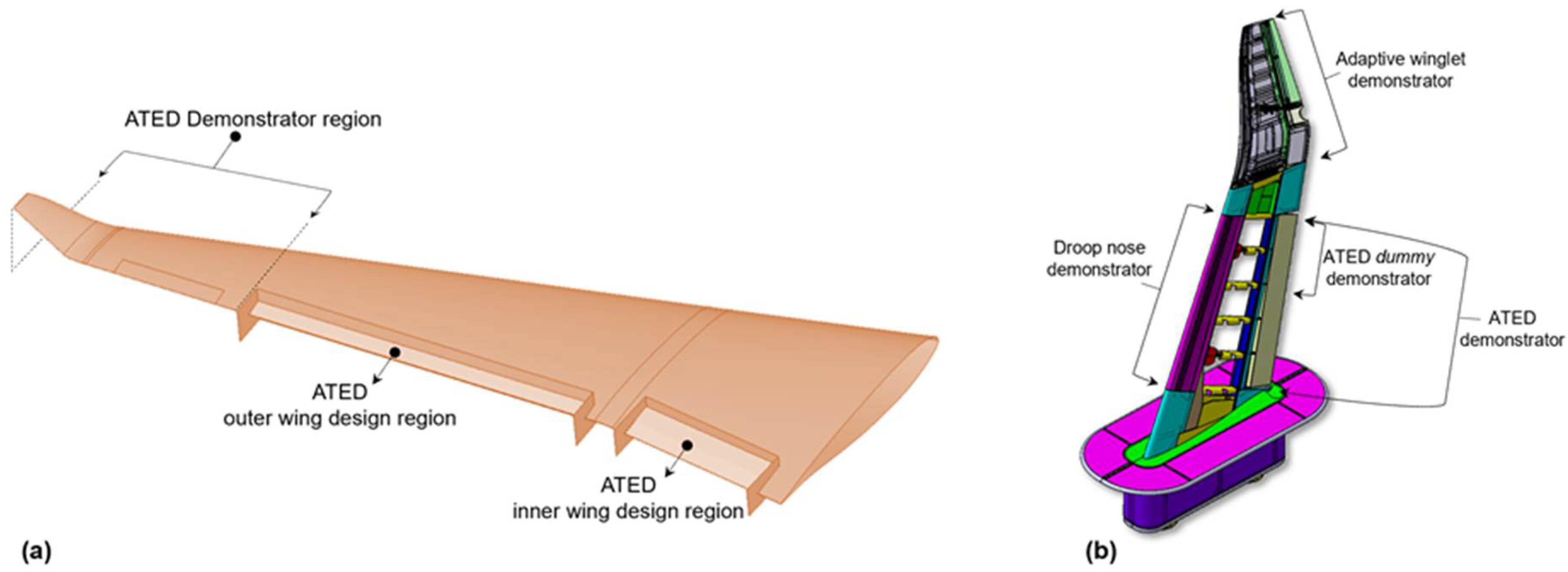
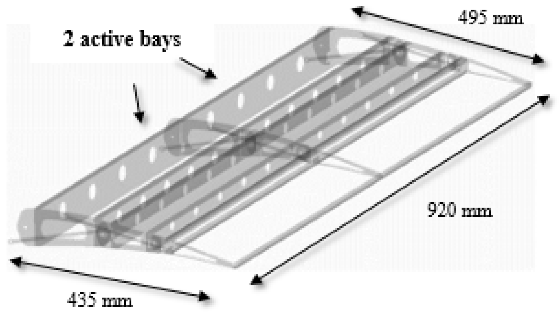
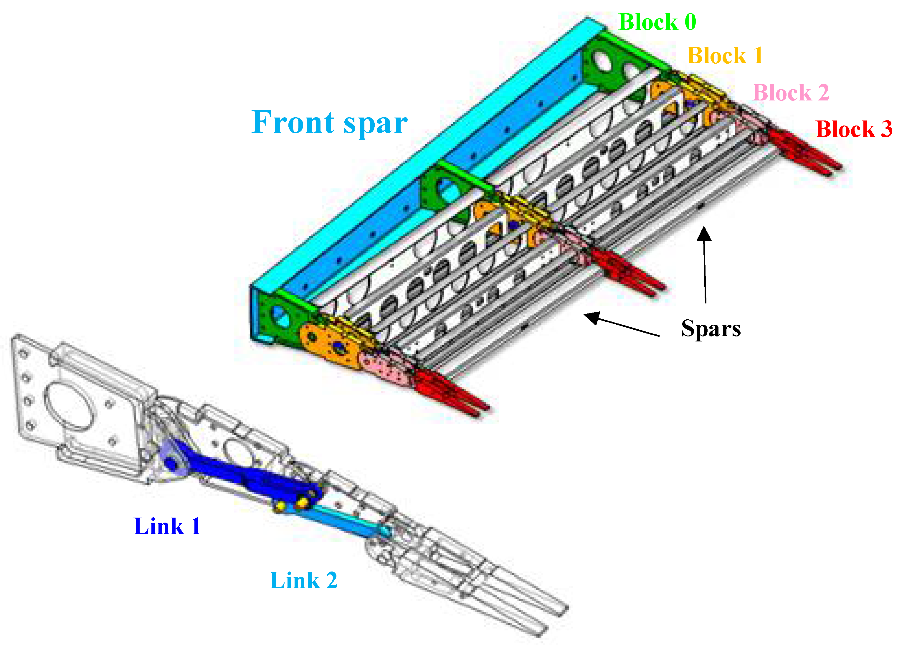
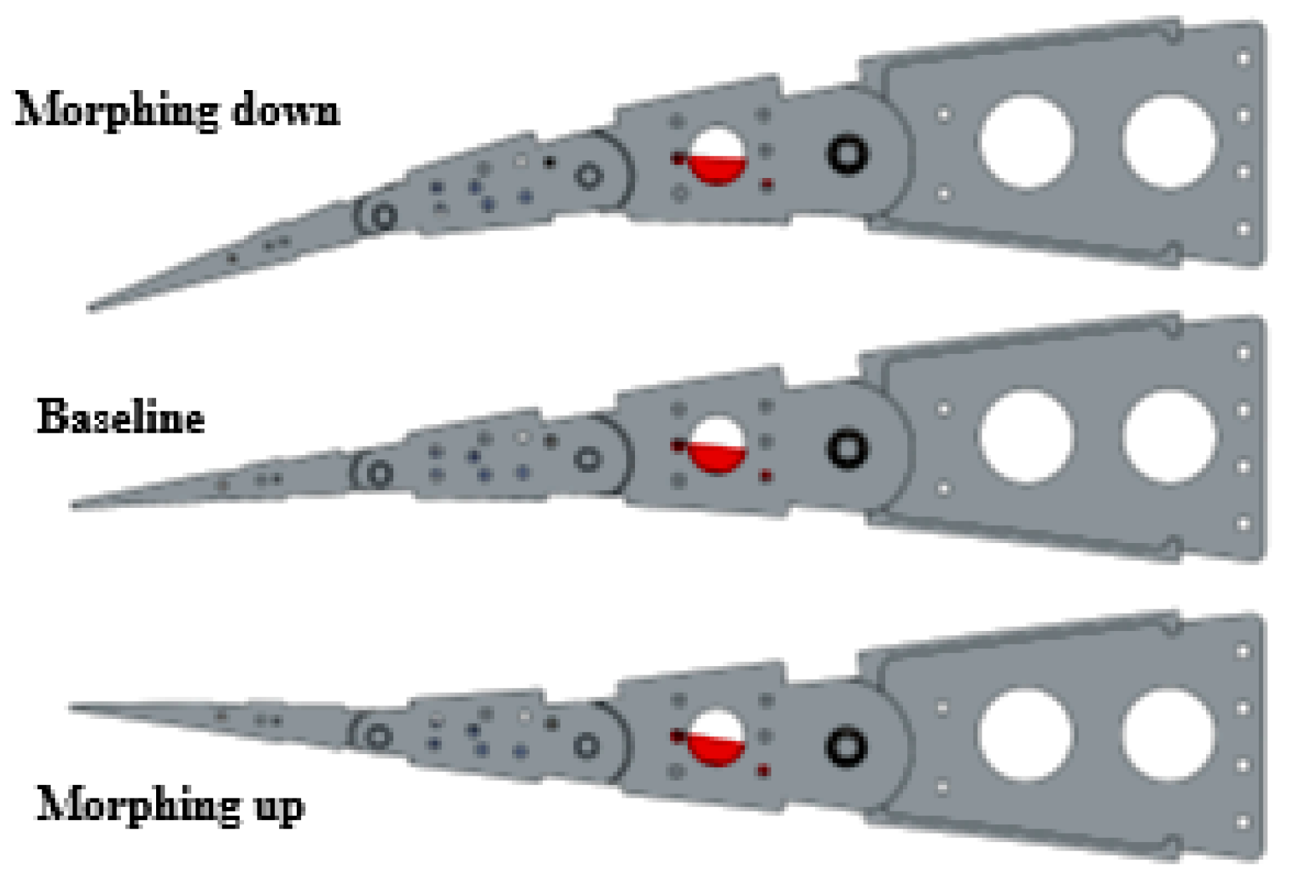
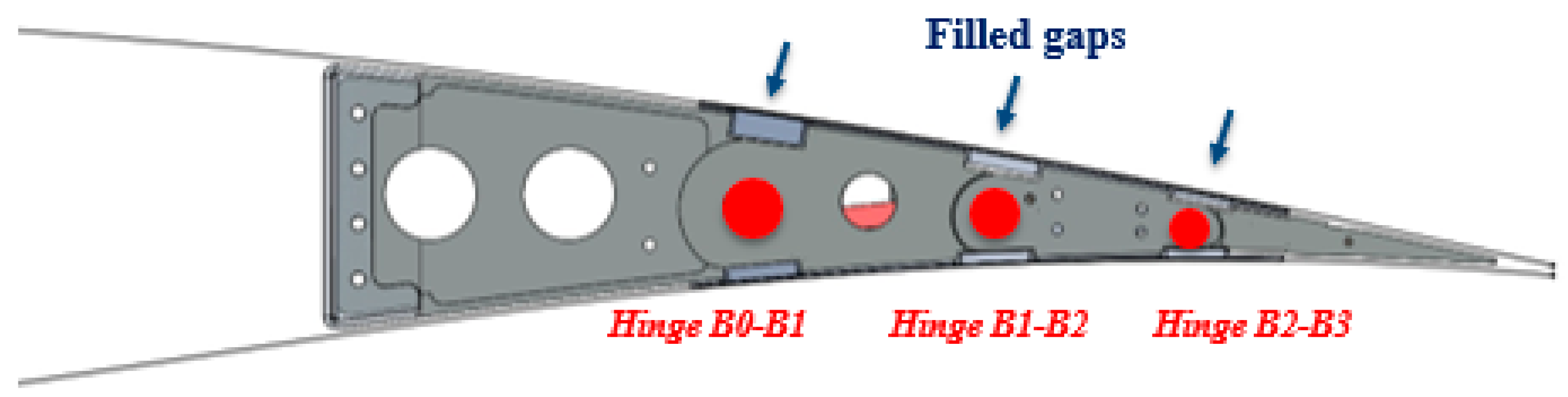
3. Morphing Architecture Description

The two-bay Adaptive Trailing Edge Device (ATED) consists of a finger-like mechanism and a multi-box arrangement (see Figure 2). Each adaptive rib was divided into four sequential blocks (B0, B1, B2, B3) jointed by hinges positioned along the aerodynamic camber line (hinge A, B, C). Block B0 is assumed to be constrained to the rear spar of the wing; the rotation of the other blocks around the respective hinge lines physically transforms the camber line into an articulated layout of consecutive parts (see Figure 3). The blocks rotations are limited by rigid links (L1, L2)—hinged to non-adjacent blocks—which induce the camber line segments to rotate according to pre-defined gear ratios. The linking elements make each rib a single-DOF mechanism: if the motion of any one of the blocks is prevented, no shape change can be achieved. On the other hand, if an actuator moves any of the blocks, the kinematic chain follows the rotation consequently. The segments can move synchronously along the span-wise direction both upwards (morphed up mode) and downwards (morphed down mode), as in Figure 4.
The finger-like mechanism of the rib thus transforms the camber line into an articulated geometric line, which can exhibit different configurations depending on the relative angles between the adjacent blocks. The choice of the number of blocks is crucial to ensure that the shape is as close as possible to the design targets. A larger number of small blocks certainly guarantees a more accurate reproduction of the camber-morphing trajectories. However, this solution could significantly increase the manufacturing costs (due to a higher number of parts) and have detrimental effects on system reliability and safety. Conversely, a reduced number of blocks can lead to a strong simplification of the structural arrangement—at the expense, however, of the shape accuracy requested by high-fidelity aerodynamic predictions.

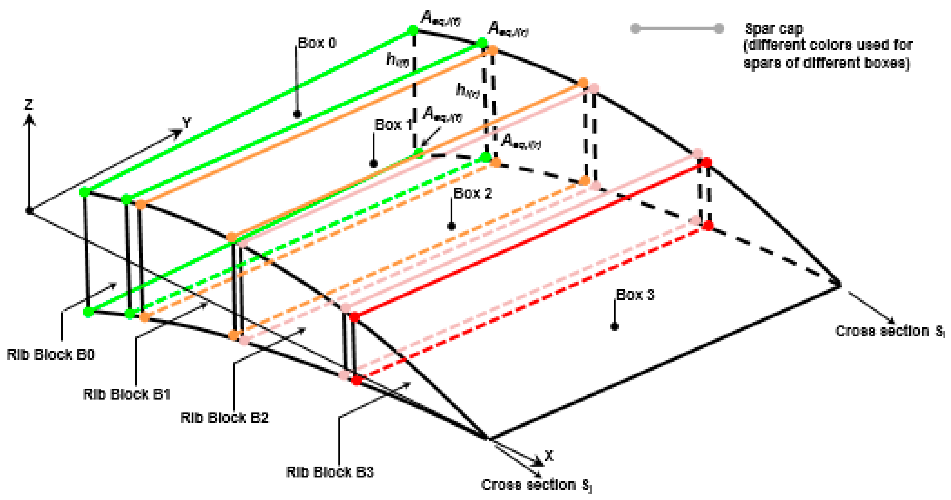
4. Skeleton Structural Sizing

As seen in the previous paragraph, the proposed architecture enables the shape morphing through an articulated arrangement of consecutive blocks connected to each other by hinges located along the trailing edge camber. For structural sizing purposes, the presence of the hinges was neglected and the structural layout of the generic bay was assumed to be an assembly of single-cell sectors, rigidly interconnected to each other, in a multi-box arrangement (Figure 5). Each cell is delimited along the span-wise direction by homologue blocks of consecutive ribs, and along the chord by longitudinal stiffening spars.
The structural sizing of each cell was performed by referring to the classical theory of the thin-walled section beams [36], under the following hypotheses:
  • Al2024-T5 alloy for all primary elements comprising rib plates, spars and skin panels;
  • limit load condition associated to a trimmed flight symmetric manoeuvre, at dive speed, limit load factor and maximum take-off weight);
  • no coupling among the hinged blocks along the chord-wise direction (in more detail, each cell of the multi-block arrangement was analysed independently);
The three-dimensional un-viscid vortex lattice method was used to calculate the pressure distribution along the wing. The aerodynamic model was obtained by meshing the wing into 16 flat panels further subdivided into 1860 boxes (Figure 6, panels boundaries are represented by means of thick lines); higher mesh density was used along the trailing edge in order to better estimate the pressure trend along the ATED chord). After some sensitivity analysis, the enveloping load condition in terms of highest internal loads induced along the ATED was found to be a trimmed symmetric manoeuvre at dive speed (VD = 206 m/s, Mach = 0.65), limit positive load factor (2.5) and maximum take-off weight (60,000 Kg). Pressure distributions (upper and lower) evaluated along the centre lines of the aerodynamic strips were interpolated along ATED rib planes (Figure 7); at each rib plane, the interpolated distributions were conveniently replaced by linear piecewise distributions characterized by constant average values of (upper/lower) pressure along the chord of each rib segment block. The piecewise distributions, related to the two bays of the dummy demonstrator, are recapped in Figure 8. In compliance with EASA CS-25 airworthiness requirements, ultimate pressure distributions were obtained by multiplying the limit ones by a contingency factor equal to 1.5.
The limit (/ultimate) aerodynamic pressure was then integrated along the span-wise and chord-wise directions to get the principal solicitations components, i.e., torque, bending moment and shear along each cross section of the ATED.
The main dimensions of the structural arrangement (namely, spars and skin panel thickness, spar caps area) were determined in order to assure adequate margins of safety with respect to permanent deformations at limit load (material plasticization) and local failures at ultimate load.

5. Hyperelastic Compliant Skin
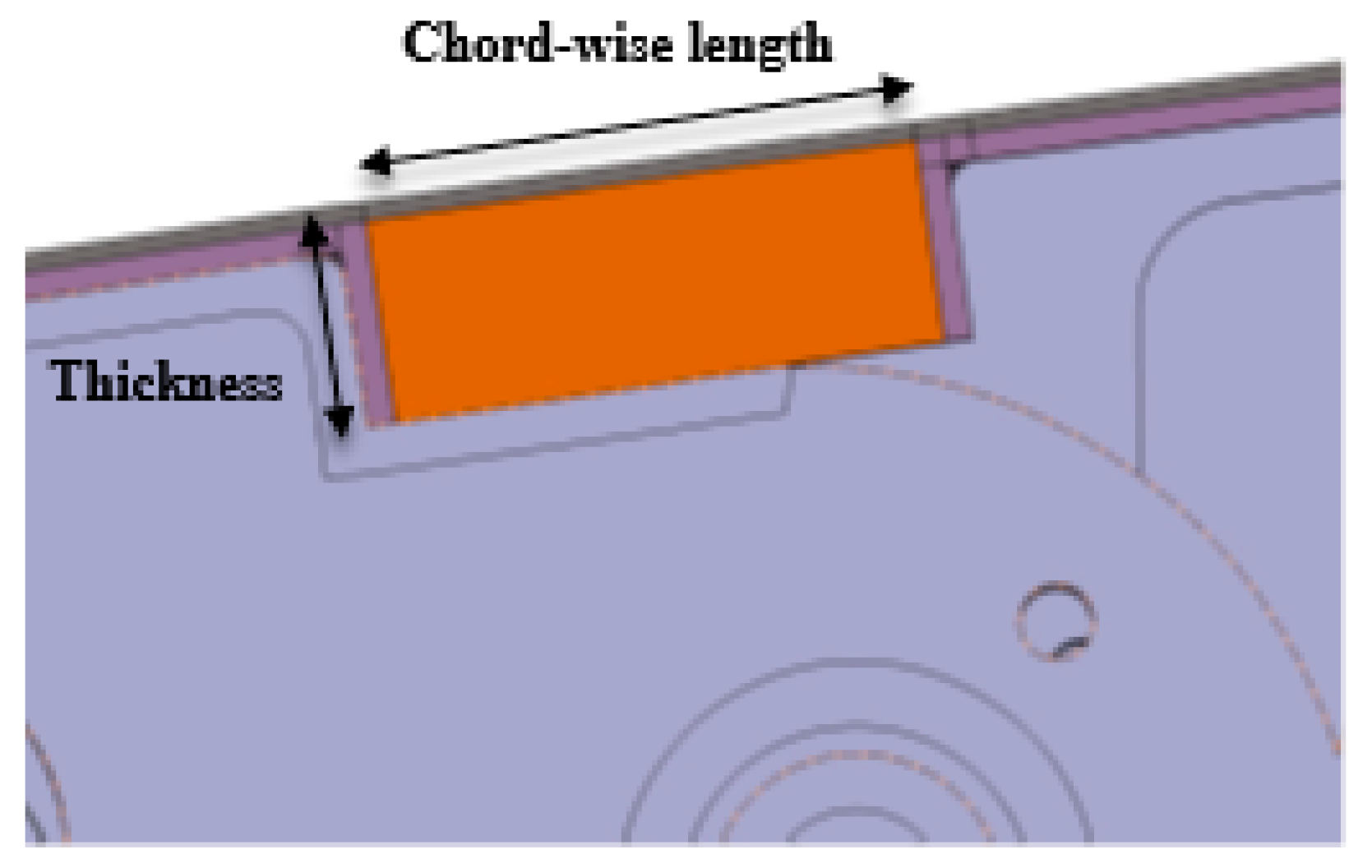
5.1. Design Aspects

In order to overcome one of the biggest challenges posed by elastomer-based morphing skins [3]—maintaining stiffness against air pressure and in-plane flexibility at the same time—a compliant skin consisting of alternating stiff and soft segments was developed. The functional principle is that soft segments take up the in-plane strains generated by trailing edge morphing, while stiff segments provide stability against air pressure. Soft segments were placed on the top and below the hinge lines, which are the regions where the highest deformations occur (see Figure 9). Conversely, almost no deformation is generated between the hinge lines due to the relatively stiff rib segments. Therefore, stiff skin segments were placed above and below the ribs.
The stiff segments of the compliant skin consist of an aluminium alloy. The space between them was filled by flexible foams, forming the soft segments. Foam and aluminium segments are covered with a protective layer of elastomer. The use of aluminium simplified also the mechanical fastening of the compliant skin to the ribs. The finalized cross section of the upper and lower skins is shown in Figure 10. The thickness of the soft segments is between 4 mm and 12 mm and the chord-wise length is between 25 mm and 30 mm, depending on thickness. These values are due to different amounts of space locally available on the primary structure and to the different air pressure levels to be counteracted along the chord-wise direction (Figure 11).

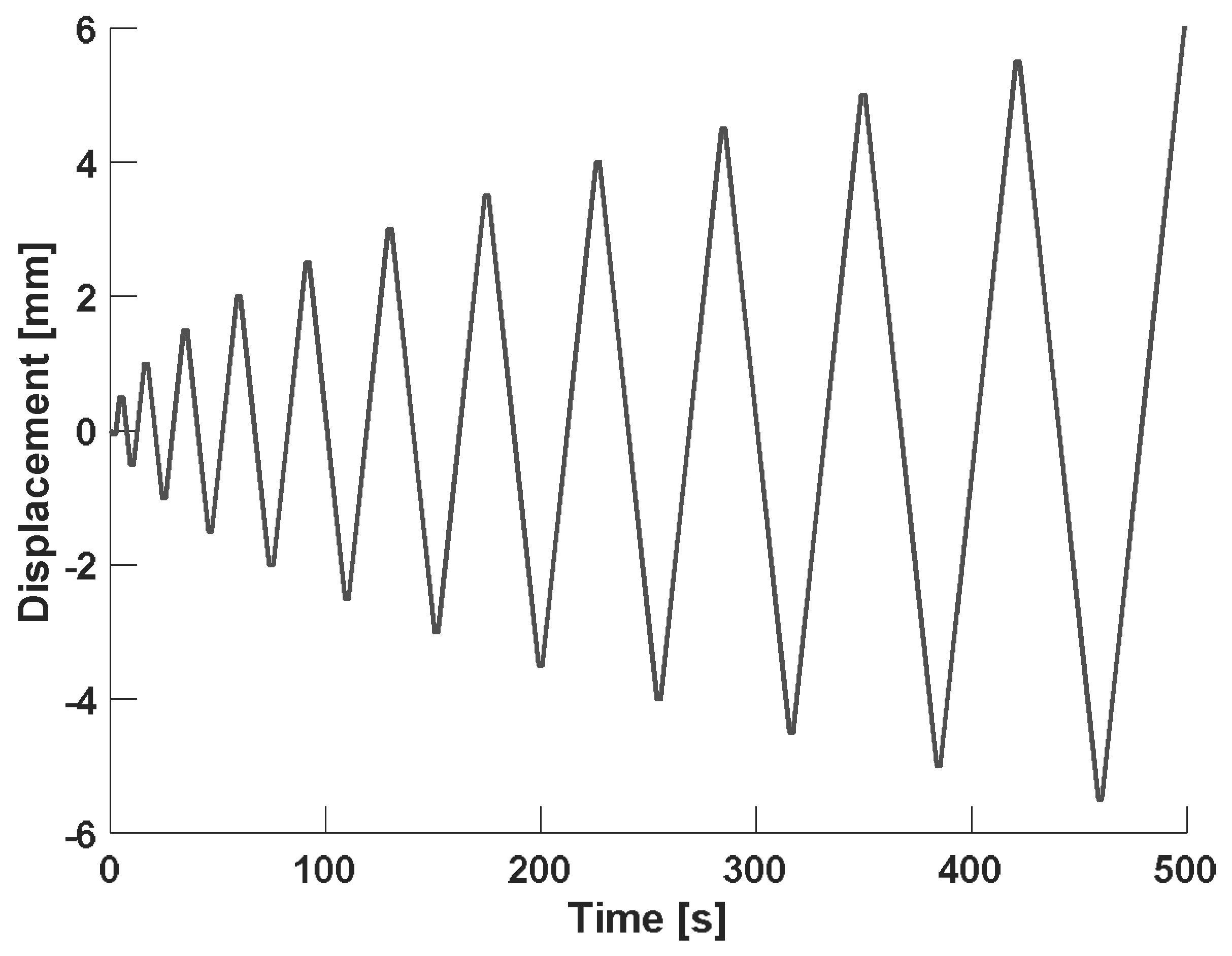
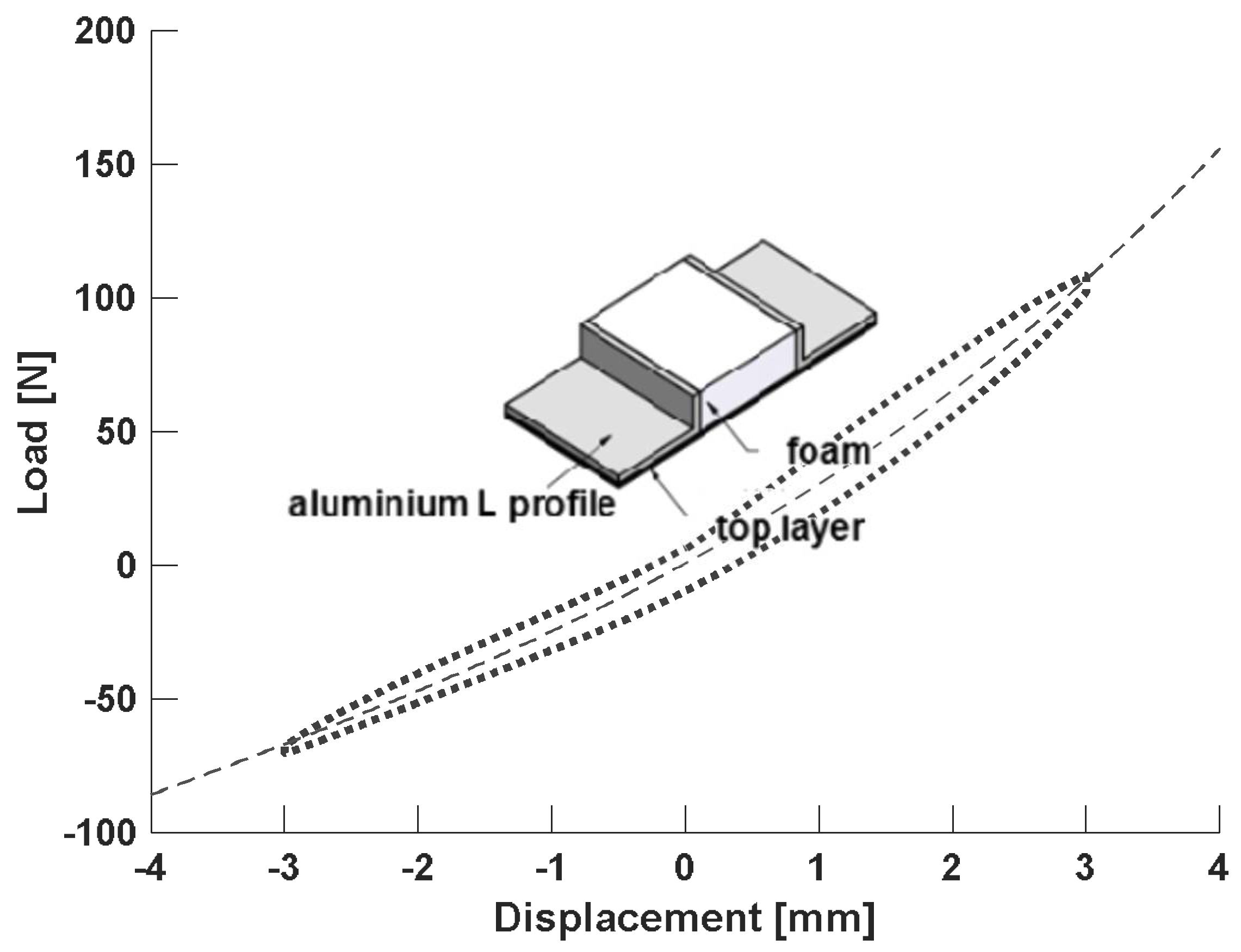
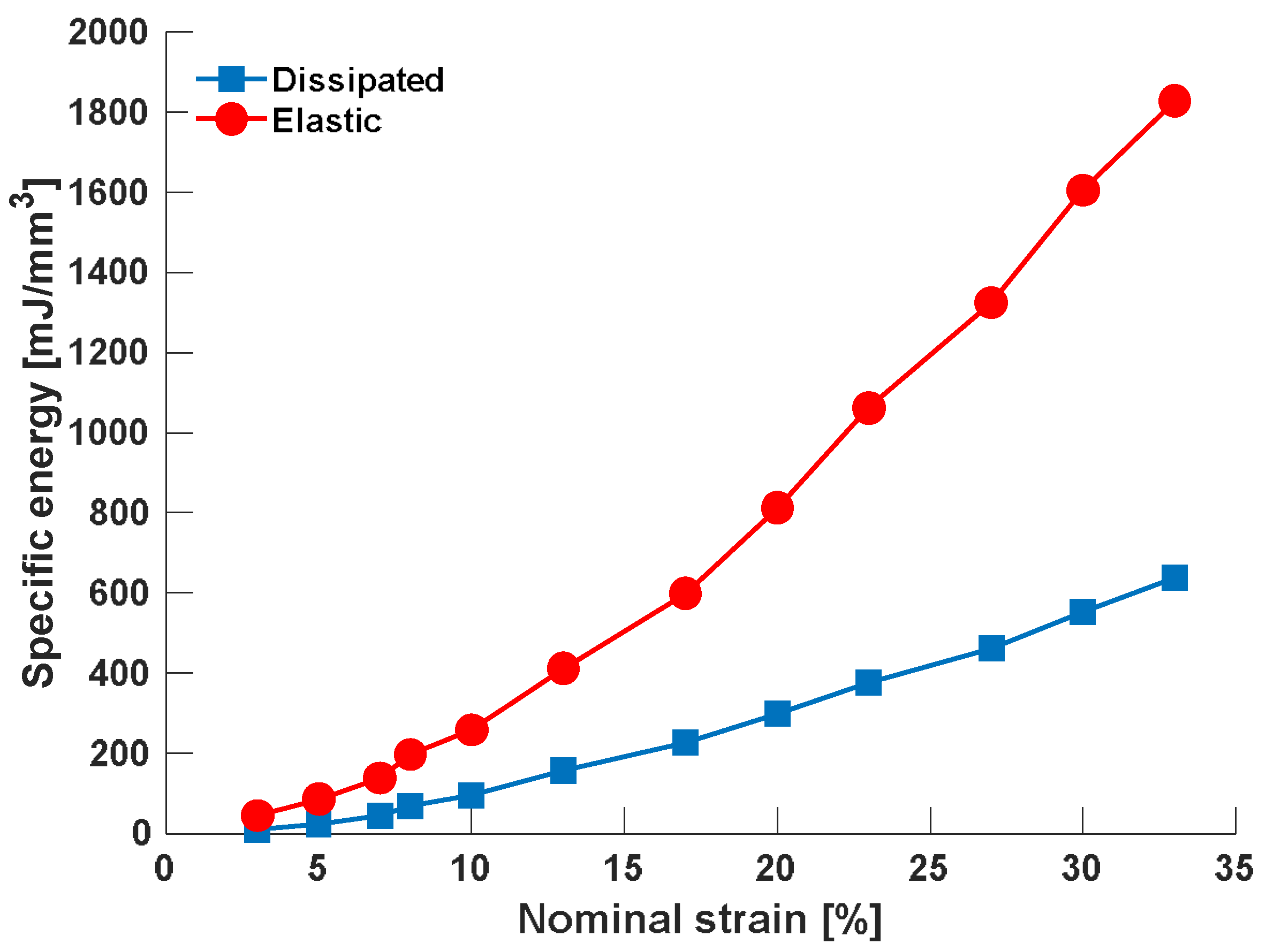
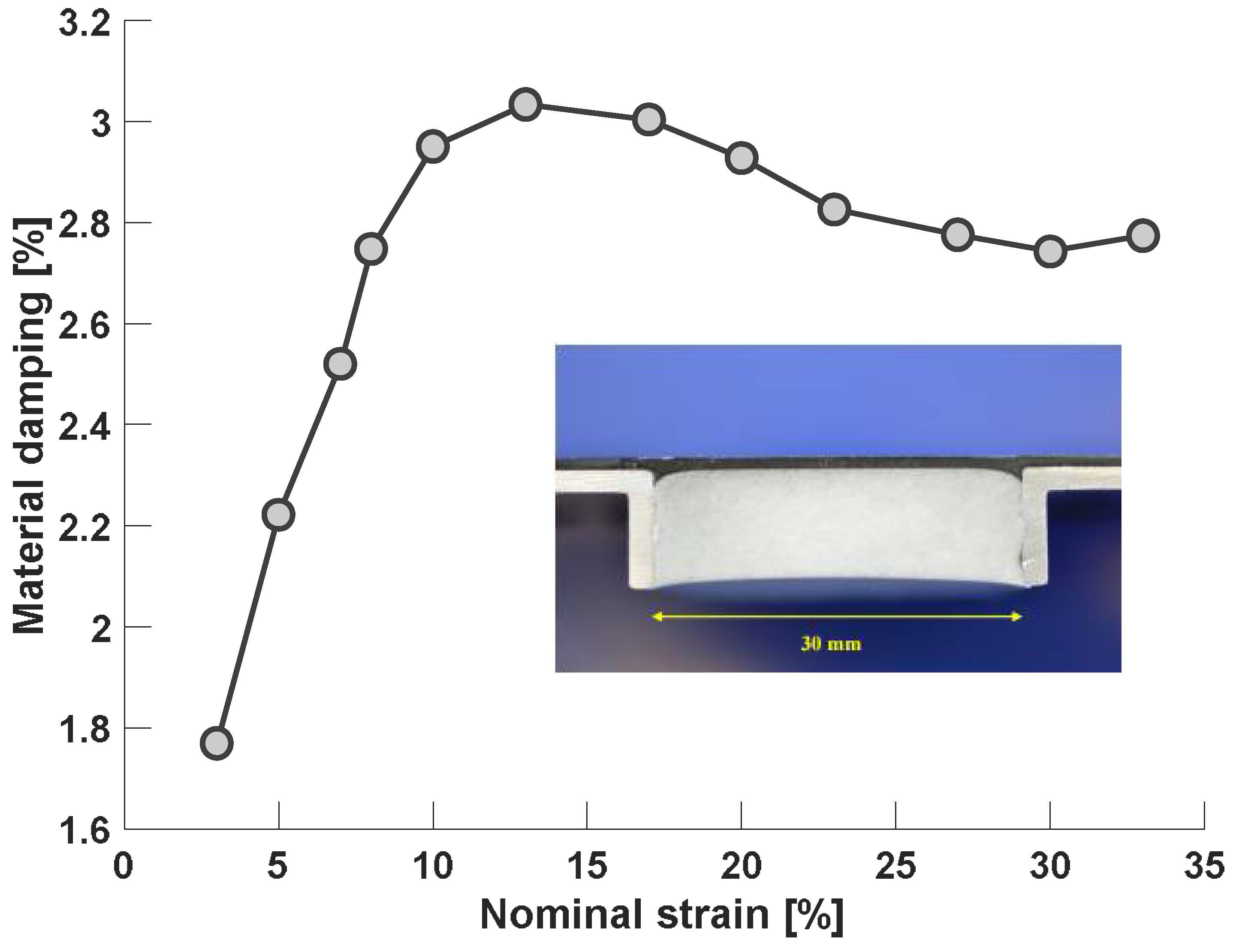
5.2. Damping Properties’ Characterization

The soft materials of the morphing skin were designed to provide adequate flexibility across the operative temperature range. Since polydimethylsiloxane (PDMS) or polytrifluoropropyl methylsiloxane lose their flexibility below −40 °C due to cold crystallization, the compliant skin material was based on polydimethyldiphenylsiloxane (PDMDPS). In this material, crystallization is effectively hindered by bulky phenyl groups. Since unfilled silicone elastomer has poor mechanical properties, the tensile strength, elongation at break and tear strength were improved by adding a filler material [37]. Flexible foam was produced from the base material by using a foaming agent that releases gas after reaching a critical temperature. The tailoring of the material was a difficult process because curing reaction and foaming reactions occurred at the same time [37]. A tailored process was also developed to perform curing, foaming, and adhesive bonding of different reactive silicones and aluminium profiles at once. The whole manufacturing process is detailed in [38]. The structural robustness of the skin was appraised through mechanical tests and wind tunnel tests [39]. Within the selected temperature range, the compliant skin showed excellent fatigue resistance and stability of interfaces (polymer‒polymer and polymer‒aluminium) [39,40]. Also, good stability against moisture and hydraulic fluid was confirmed by testing [39]. The measured initial elastic moduli of the flexible foam were between 2.30 MPa and 3.97 MPa within the operational temperature range. Poisson’s ratio values ranged between 0.15 and 0.24 [38]. The given spans represent the average of the tabulated values plus/minus one standard deviation. The initial elastic moduli of the skin were between 1.83 MPa and 2.30 MPa [38], with the span representing the average of the tabulated values plus/minus one standard deviation. Poisson’s ratio was between 0.46 and 0.47, representing the physically meaningful range of the measured values given in [38]. The damping properties of the compliant skin were investigated by exposing T-joints samples to fully reversed, cyclic loads at room temperature. Each T-joint contained a compliant skin material volume of 30 × 35 × 10 mm3 (chord length × span × thickness) and was loaded in the chord-wise direction. More details of the T-joint geometry have been published in [39,40]. A displacement-controlled, ramped cyclic test with a constant crosshead speed of 0.3 mm/s was chosen in order to match the specific operating conditions (see Figure 12). Each test was run until the sample failed. Load and displacement data were recorded throughout the test. Closed load-displacement hysteresis loops were obtained for each full cycle. A typical hysteresis loop is shown in Figure 12. The reason for the non-elliptic shape is the nonlinear behaviour of the sample, which is predominantly caused by material non-linearity.
The material damping was calculated on the basis of the mechanical energy dissipated in each cycle: this energy (Ud) is equal to the area enclosed by the hysteresis loop (see Figure 13), and was calculated by numerical integration [41]. The elastic part of the deformation energy, Uel, was estimated as the area beneath the elastic load-deflection curve, which was assumed to be linear, as depicted in Figure 12. Tensile and compressive half-cycles were considered separately. The material loss factor η was then obtained as a ratio:
η = U d 2 π U e l .
Calculated values of dissipated energy, deformation energy and damping are given in Table 1 as a function of the displacement amplitude. It can be seen that the material damping is high and ranges between 1.8% and 3%.
In order to enable the estimation of the material contribution to the overall damping of the structure, specific measures were considered necessary. The specific dissipated energy was calculated as the dissipated energy Ud per volume of compliant material contained in the T-joint, V = 10,500 mm3.
In the same way, the specific elastic energy was determined. Furthermore, the nominal strain was calculated by dividing the displacement amplitude u by the chord length of 30 mm. These quantities are given in the last three columns of Table 1. A graphical representation is shown in Figure 14. These data can be used to estimate the contribution of the compliant material to the total damping of the structure by scaling with the total volume content.
The damping ζ, assumed as:
ζ = η 2 ,
is shown as a function of the nominal strain in Figure 15. It can be seen that the damping is dependent on strain. It starts at 0.23 at 3% strain and goes up to a maximum of 0.38 at 15% strain. The decrease in damping observed at strain values higher than 15%, is a consequence of the linearity assumption drawn in the data evaluation. Since the operational strain values are below 15%, the exact damping curve is only needed up to this value.

6. Numerical Model Overview

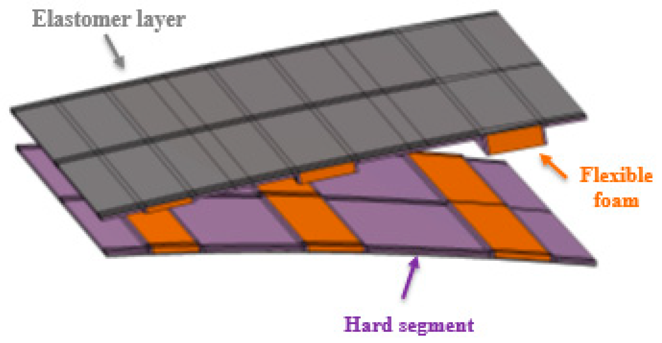
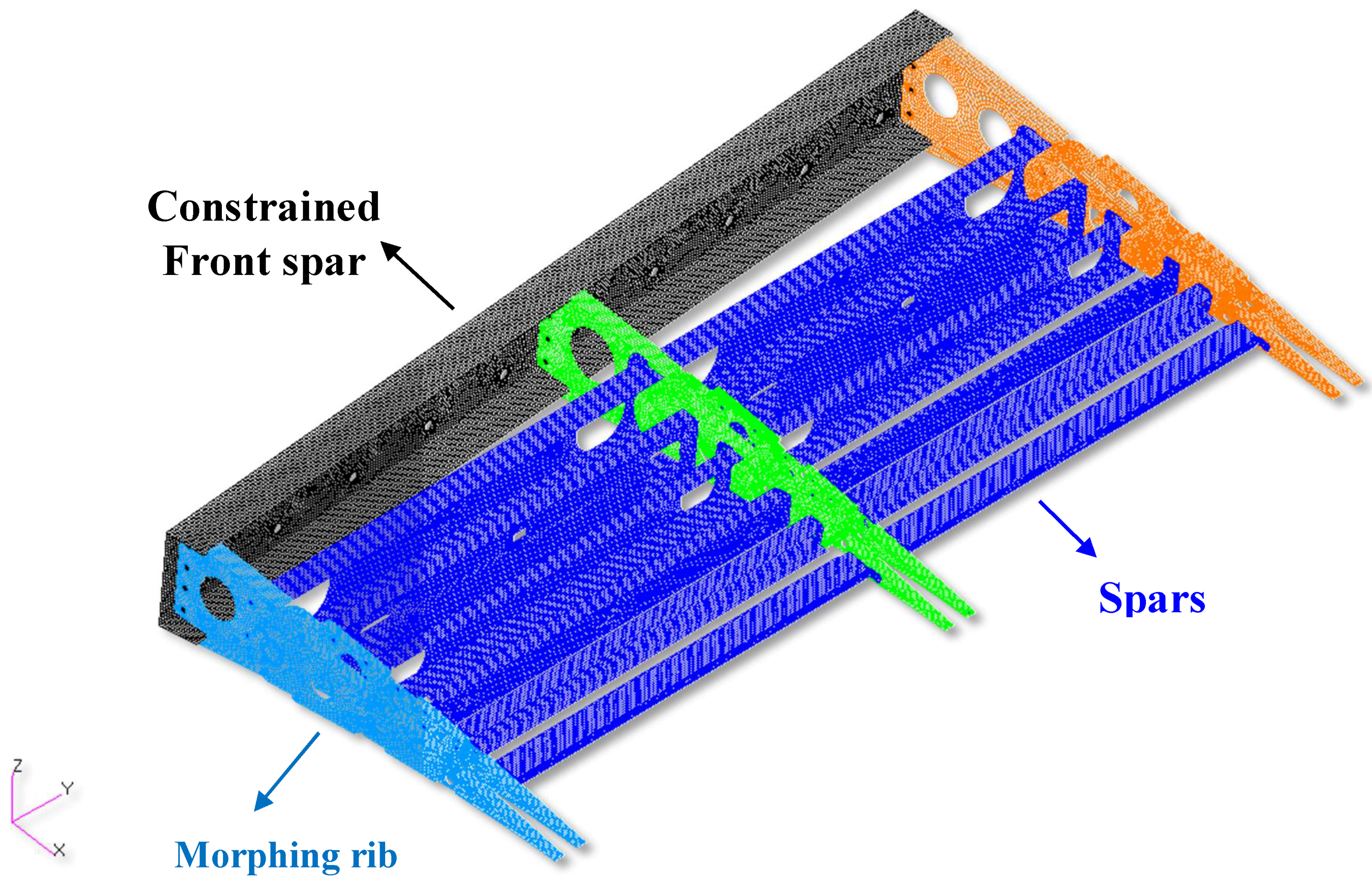
6.1. Structural Modelling

The detailed modelling of a morphing system involves a proper schematization of several components and subassembly items, such as the ribs, connected by spherical and cylindrical joints, the actuator chains, including motor shaft, the skin and the spars, among the others. All elements are fastened and must be compliant with the operative and safety loads (Limit and Ultimate Loads) [33,34]. In this work, the load-bearing actuation system is not covered by the analyses in order to characterize the single contribution of the skin on the generalized stiffness of the morphing structure. FE analyses were all carried out in MSC Nastran® environment [42]. The model includes the primary structure (morphable and un-morphable boxes) and the skin segments: aluminium panels as well as hyperelastic sheets and foam segments along the morphing regions. The internal hinges (spherical and cylindrical) are modelled with the usual scheme of rigid body connections (rbe2), with independent nodes located to an ideal centre of rotation [42]. For each hinge, a local coordinate system defying internal rigid body is defined. The hinges kinematics is modelled by coupling the DOF of master independent node and slave nodes: pin release at the end-nodes of bar-cbeam elements to allow the relative rotation between the connected items has been imposed [42]. All the grids of the trailing edge front spar were constrained in all six degrees of freedom (see Figure 16).
The global finite element model consisted of a high number of nodes and elements, necessary to properly represent the trailing edge geometrical layout. All the components of the morphing device, apart from the steel links and actuation chains, were made of aluminium (Al2024-T3). The morphing skin (shown in Figure 17) is composed of a three-level structure:
  • An aluminium sheet (plate-cquad4), connected to the rib;
  • A hyperelastic sheet (plate-cquad4), covering all the structure;
  • Foam strips (solid-chexa8), applied in span-wise direction and located close to the hinges to guarantee the morphing capability to the skin.
The mechanical properties assumed for the adopted materials are listed in Table 2, while the model mesh data are recapped in Table 3.

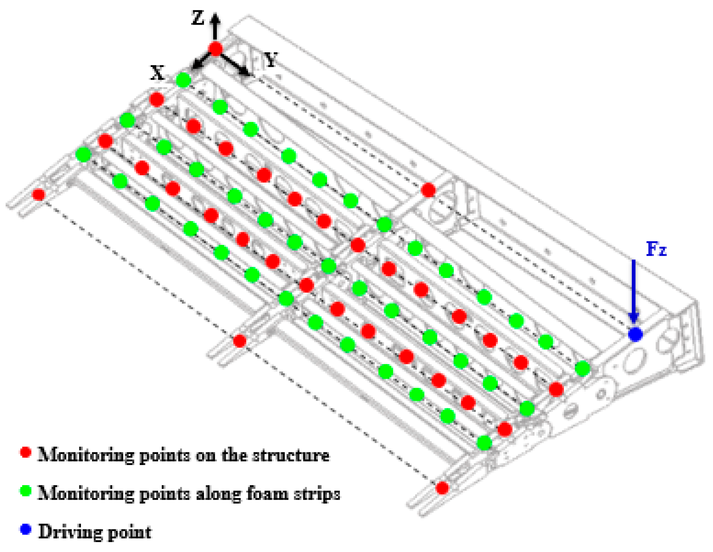
6.2. Parametric Normal Modes Analysis

A modal analysis was carried out to predict the dynamic behaviour of the structure for different values of stiffness and inertial parameters. The modal parameters were extracted by varying the mechanical properties of the skin in the range between the minimum and the maximum values listed in Table 1. Considering the spectral range [0, 200 Hz], the main resonance frequencies of the system changed consequently, Figure 18. The (undamped) modal shapes of interest are shown in Figure 19. The compliant skin contribution to the generalized stiffness of the global morphing system was then characterized. The morphing mode, which is predominantly a kinematic rigid movement at zero frequency, is here characterized by a not-null vibrating frequency. In the absence of the actuation system, the rigid motion of the morphing structure is indeed prevented by the compliant skin, which makes a unique contribution to the (not-null) modal deformation energy.

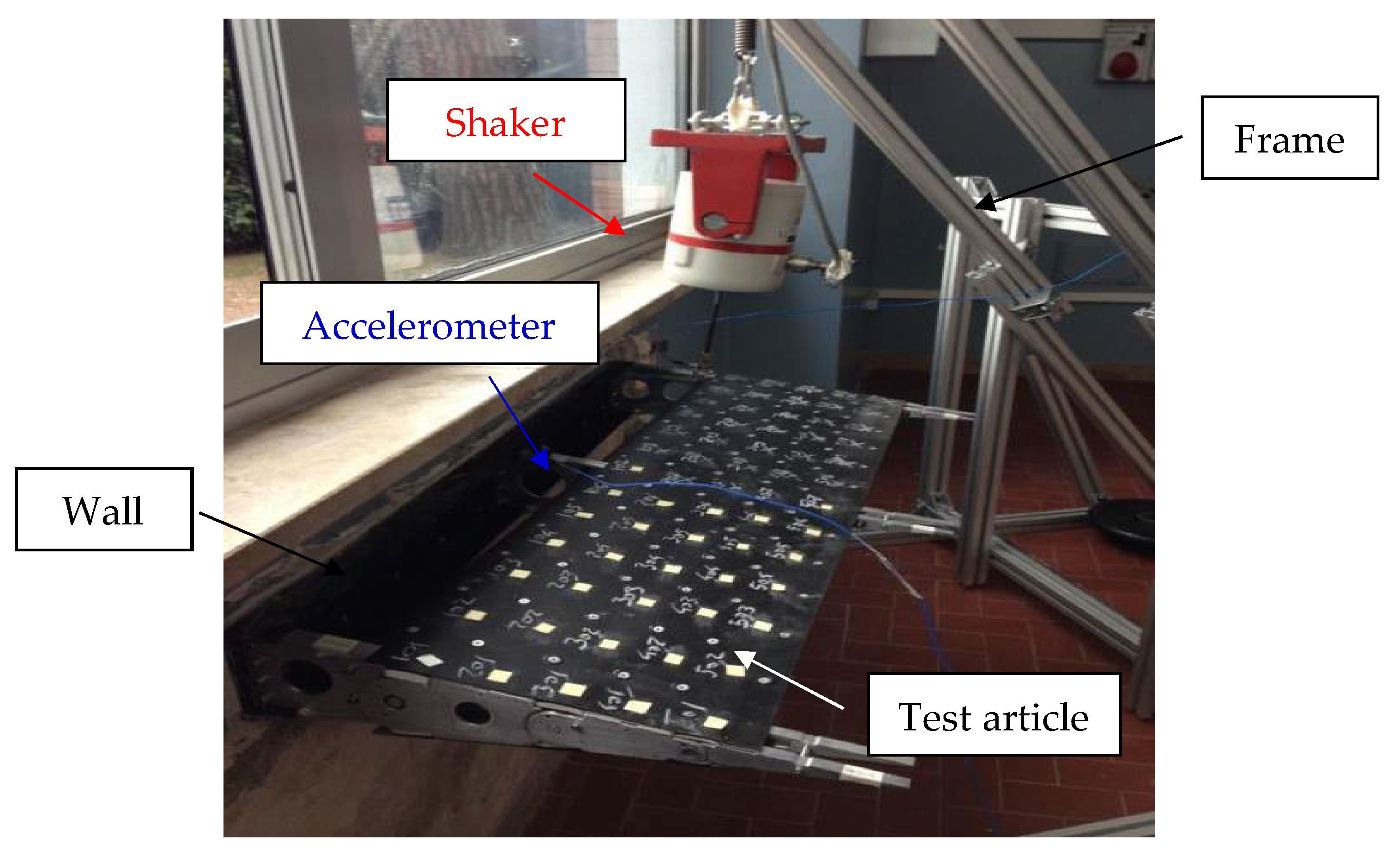
7. Experimental Investigation of Dummy Device

7.1. Test Setup Description

Frequency response functions (FRFs) were used to measure and characterize the dynamic behaviour of the structure. It was clamped at its front spar but free at the other end (Figure 20). The excitation system consisted of a shaker, which was connected by a rigid stringer to the structure in correspondence of the block 0 of the rib 1. A purely random signal was used in the range 0–200 Hz for the appropriation of the resonance frequencies. An experimental grid of 71 acquisition points was used to reconstruct the mode shapes. Five span-wise stations were monitored (corresponding to each of the three ribs, and in the middle of each bay); at each station, three reference points were selected chord-wise, at the edges and at the middle of each foam strip.
A schematic of the acquisition layout and a photo of the test setup are shown in Figure 21 and Figure 22, respectively. The adopted reference system is a Cartesian orthogonal one and was originated on the block 0 of rib 3 in the point O. The X-axis was placed along the rib on intermediate surface; the Y-axis was placed along the foam strip orthogonal to X-axis. The tests were carried out by placing the accelerometer on the first point and rowing it step-by-step on all grid points, recording datasets at each step.

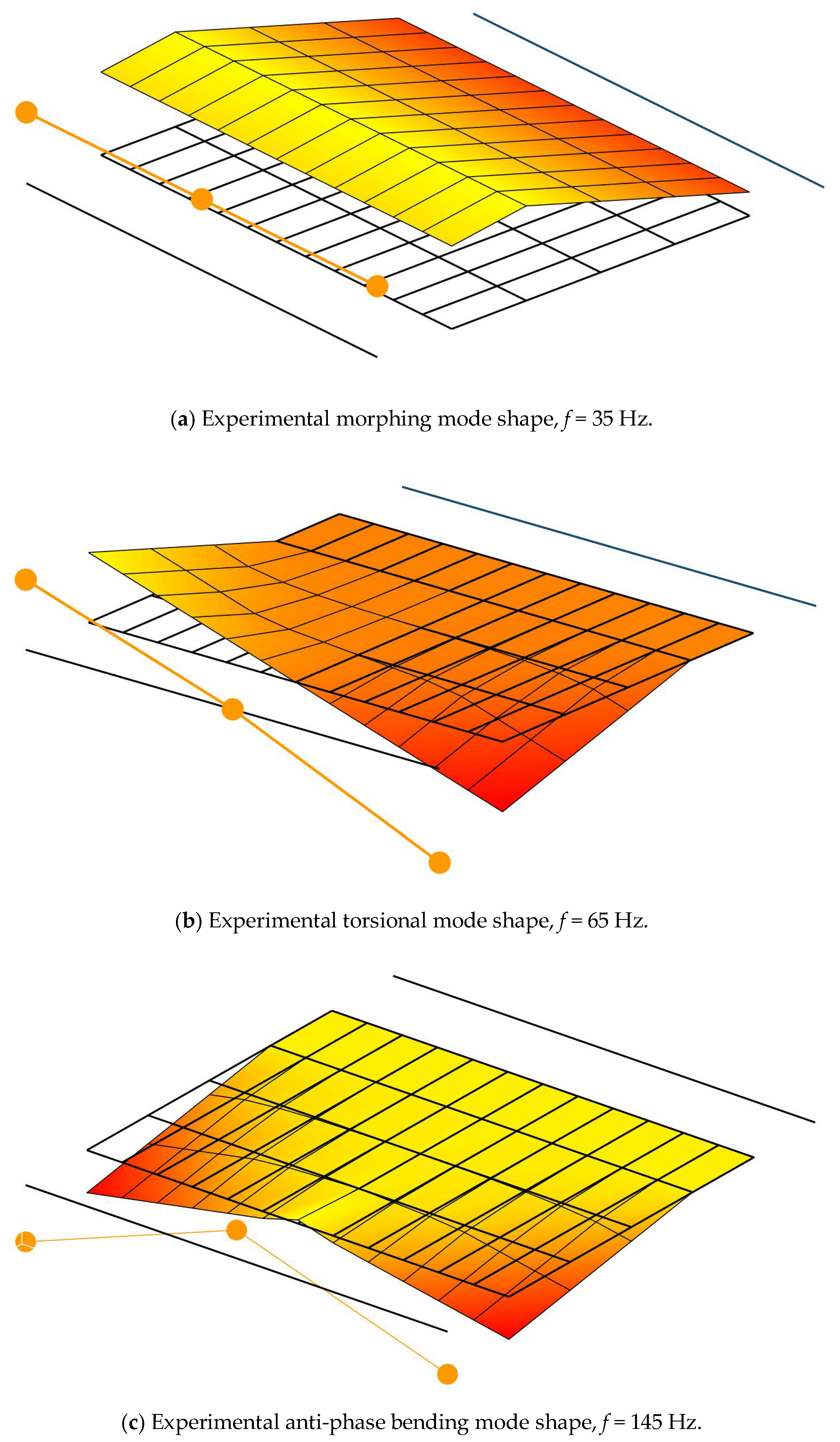
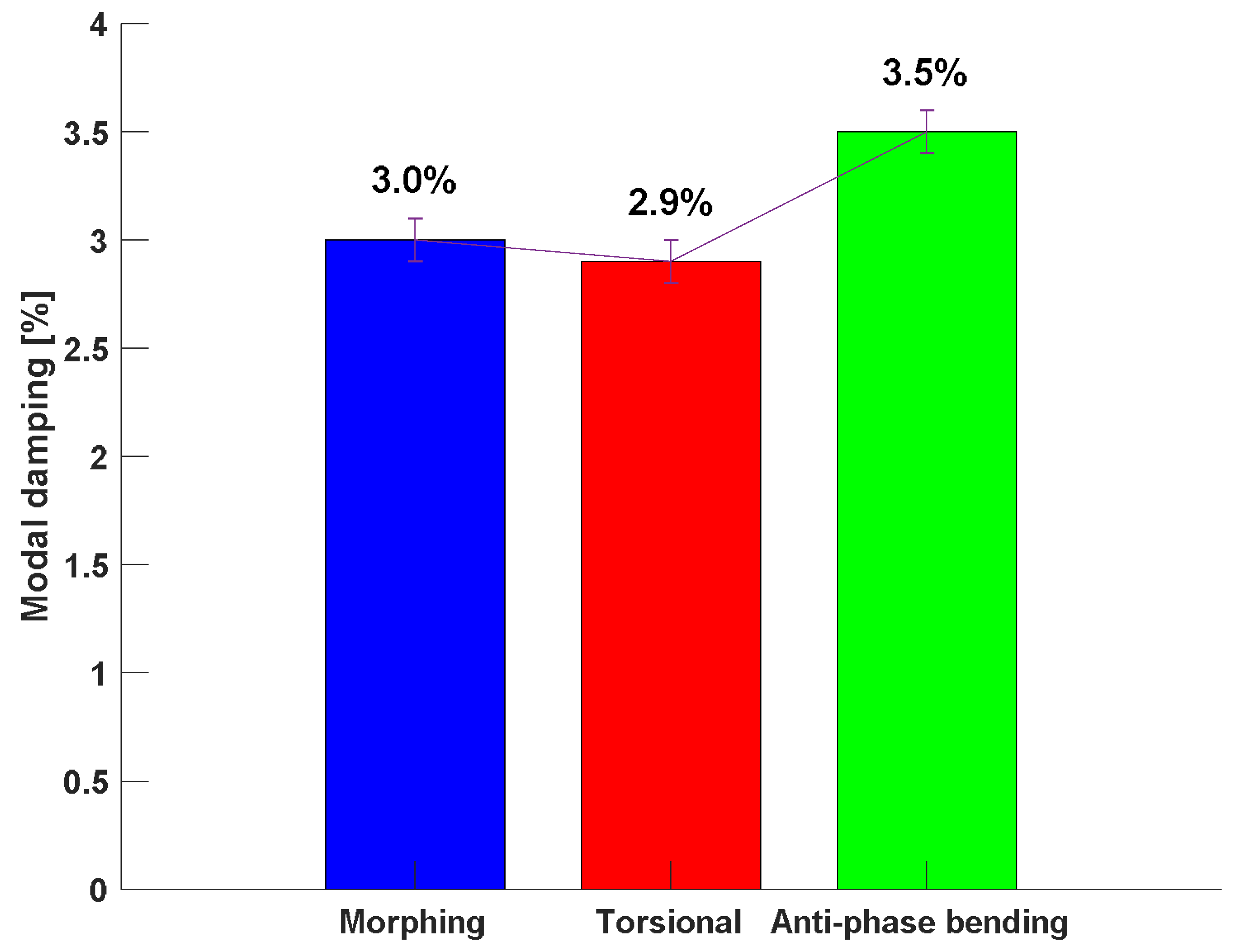
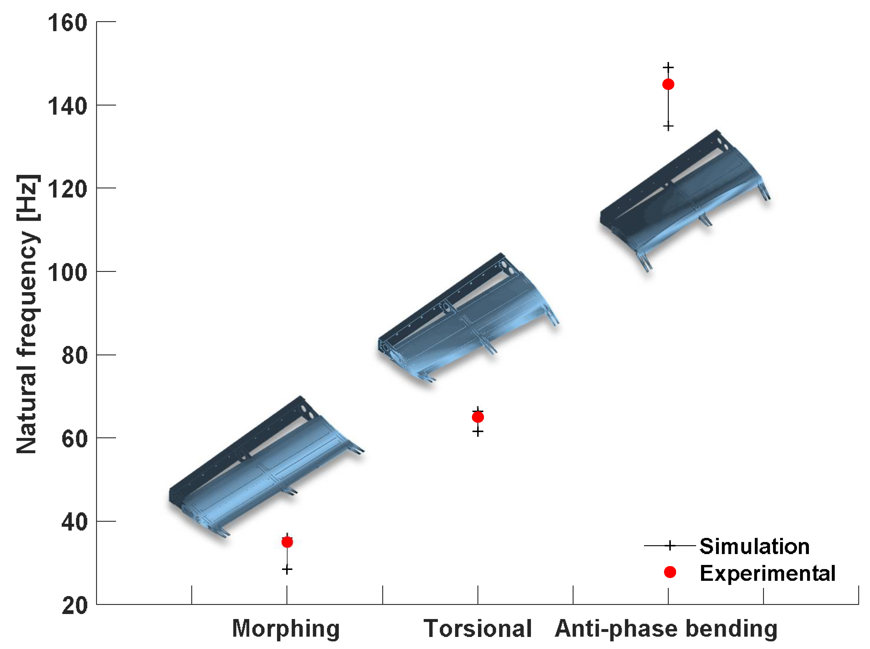
7.2. Ground Vibration Test Results

The experimental modal analysis was carried out for two main purposes: a modal correlation with the numerical results and the estimation of the damping coefficient. The test results confirmed an interesting behaviour of the device: the damping levels were much higher than those typical of metal structures (generally about 1–1.5%) starting from the very first mode shapes. This mechanism, in line with what has already been observed on the single sample, increases the dissipation of energy, which resulted in a higher damping coefficient. In particular, modal damping increased to 3.5% as the frequency grew because of the actual boundary condition, which affected skin compression and stretching to a significant extent during the modal deformations. The experimental mode shapes are represented in Figure 23. These remarkable outcomes confirmed that the morphing skin increased the generalized stiffness of the adaptive structure, as already foreseen by the simulations, by playing the function of a dynamic energy dissipator (Figure 24).
Figure 25 shows for each mode the deviation between experimentally measured and numerical evaluated frequencies. It is worth noting that the test data are within the predicted numerical range.

8. Conclusions

Adaptive structures are a topic of growing interest in the aviation industry since they can bring several benefits to next-generation aircraft. An adaptive trailing edge concept is herein presented by combining conventional parts and innovative concepts, as for the morphing skin, all assembled into a new structural system. The structure selected for the benchmark problem is a two-bay portion of an outboard wing trailing edge, consisting of three articulated (finger-like) rib covered by a multi-material hyperelastic skin. The authors have investigated some important aspects for the design and validation of the adaptive system. Focus has been given to the integration issues of a multi-block structure with a high-elasticity compliant skin. The skin influences the global structural dynamics in terms of its mass, damping and stiffness. On the one hand, the inclusion of a compliant skin contributes to make the morphing structure more stable, thanks to its stiffness. The rigid motion of the mechanical structure, necessary to morph the shape of the system, is in fact “counteracted” by the multi-segment skin deformation. Both numerical and testing outcomes highlighted that the morphing frequency, typically representative of a multi-body rigid mode close to 0 Hz, is instead about 35 Hz, even in the absence of the actuation system, which generally affects such a mode by introducing torsional stiffness. On the other hand, the increased weight due to the skin, which could also be a relevant percentage of the complete system, leads to a further increment of the modal density at low frequency, thereby introducing more elastic modes in the bandwidth where flutter instabilities are more likely to occur. The outcomes have demonstrated an intrinsically higher damping coefficient than the standard metallic systems: the elastomeric skin increases the system global property to disperse vibrational energy, reducing the resonance amplitudes. In the preliminary experimental investigations, carried out on a simplified mock-up of the final SARISTU demonstrator, this damping trend has been well assessed in several percentage units, in line with the expectations. The outcomes of the dynamic test have de facto confirmed those levels investigated on stand-alone skin samples by means of mechanical tests only. In more detail, the morphing skin contributes decisively to the modal damping of the entire structure by ensuring 3–3.5% damping compared to 1–1.5% of the aluminium structure alone. Further studies are planned to assess the behaviour of the structure by also taking into account the contribution of the actuators and transmission chains to the overall stiffness of the morphing device.

Author Contributions

Conceptualization: M.A., R.P., O.S., and A.C.; Methodology: M.A., R.P., and C.N.; Software: M.A. and C.N.; Validation: M.A., C.N., and I.D.; Formal analysis: All; Investigation: All; Resources: R.P., O.S. and A.C.; Data curation: M.A. and C.N.; Writing—original draft preparation: M.A. and C.N.; Writing—review and editing: R.P., I.D., A.C.; Visualization: M.A. and C.N.; Supervision: R.P., O.S. and A.C.; Project administration: R.P., O.S., A.C. and I.D.

Funding

The research outlined in this paper exploits concepts and technologies developed in the framework of the SARISTU project (under Grant Agreement n° 284562 of FP7/2007-2013).

Acknowledgments

The authors wish to thank all SARISTU partners involved in the design and validation of the morphing trailing edge device.

Conflicts of Interest

The authors declare no conflict of interest.

References and Note

  1. Sofla, A.Y.N.; Meguid, S.A.; Tan, K.T.; Yeo, W.K. Shape morphing of aircraft wing: Status and challenges. Mater. Des. 2010, 31, 1284–1292. [Google Scholar] [CrossRef]
  2. Barbarino, S.; Bilgen, O.; Ajaj, R.M.; Friswell, M.I.; Inman, D.J. A review of morphing aircraft. J. Intell. Mater. Syst. Struct. 2011, 22, 823–877. [Google Scholar] [CrossRef]
  3. Thill, C.; Etches, J.; Bond, I.; Potter, K.; Weaver, P. Morphing skins. Aeronaut. J. 2008, 112, 117–139. [Google Scholar] [CrossRef]
  4. Thornburgh, R.P.; Kreshock, A.R.; Wilbur, M.L.; Sekula, M.K.; Shen, J. Continuous Trailing-Edge Flaps for Primary Flight Control of a Helicopter Main Rotor. In Proceedings of the 20th American Helicopter Society (AHS) Annual Forum, Montreal, QC, Canada, 20–22 May 2014. [Google Scholar]
  5. Wilbur, M.L.; Mistry, M.P.; Lorber, P.E.; Blackwell, R., Jr.; Barbarino, S.; Lawrence, T.H.; Arnold, U.T.P. Chapter 24—Rotary Wings Morphing Technologies: State of the Art and Perspectives, Morphing Wing Technologies Large Commercial Aircraft and Civil Helicopters; Elsevier: Amsterdam, The Netherlands, 2018; pp. 759–797. [Google Scholar]
  6. Qiu, J.; Wang, C.; Huang, C.; Ji, H.; Xu, Z. Smart skin and actuators for morphing structures, 23rd International Congress of Theoretical and Applied Mechanics. Procedia IUTAM 2014, 10, 427–441. [Google Scholar] [CrossRef]
  7. Ermakova, A.; Dayyani, I. Shape optimisation of composite corrugated morphing skins. Compos. Part B Eng. 2017, 115, 87–101. [Google Scholar] [CrossRef]
  8. Airoldi, A.; Crespi, M.; Quaranti, G.; Sala, G. Design of a Morphing Airfoil with Composite Chiral. Struct. J. Aircr. 2012, 49, 1008–1019. [Google Scholar] [CrossRef]
  9. Wu, R.; Sun, J.; Chang, Z.; Bai, R.; Leng, J. Elastic composite skin for a pure shear morphing wing structures. J. Intell. Mater. Syst. Struct. 2014, 26, 352–363. [Google Scholar] [CrossRef] [Green Version]
  10. Woods, B.K.S.; Friswell, M.I. The Adaptive Aspect Ratio Morphing Wing: Design Concept and Low Fidelity Skin Optimization. Aerosp. Sci. Technol. 2015, 42, 209–217. [Google Scholar] [CrossRef]
  11. Beaverstock, C.S.; Woods, B.K.S.; Fincham, J.H.S.; Friswell, M.I. Performance Comparison between Optimised Camber and Span for a Morphing Wing. Aerospace 2015, 2, 524–554. [Google Scholar] [CrossRef] [Green Version]
  12. Gurses, E.; Tuncoz, I.O.; Yang, Y.; Arslan, P.; Kalkan, U.; Tıras, H.; Sahin, M.; Ozgen, S.; Yaman, Y. Structural and aerodynamic analyses of a hybrid trailing edge control surface of a fully morphing wing. J. Intell. Mater. Syst. Struct. 2016, 28, 979–991. [Google Scholar] [CrossRef]
  13. Tai, H. Shape sensing a morphed wing with an optical fiber Bragg grating. In Proceedings of the SPIE Conference on Smart Structures and Materials, Nondestructive Evaluation and Health Monitoring, San Diego, CA, USA, 19 May 2005. [Google Scholar]
  14. Viscardi, M.; Arena, M.; Barra, G.; Vertuccio, L.; Ciminello, M.; Guadagno, L. Piezoresistive strain sensing of carbon nanotubes-based composite skin for aeronautical morphing structures. In Proceedings of the SPIE 10599, Nondestructive Characterization and Monitoring of Advanced Materials, Aerospace, Civil Infrastructure, and Transportation, Denver, CO, USA, 27 March 2018. [Google Scholar]
  15. Viscardi, M.; Arena, M.; Guadagno, L.; Vertuccio, L.; Barra, G. Multi-functional nanotechnology integration for aeronautical structures performance enhancement. Int. J. Struct. Integr. 2018, 9, 737–752. [Google Scholar] [CrossRef]
  16. Sun, G.; Wua, Y.; Lia, H.; Zhua, L. 3D shape sensing of flexible morphing wing using fiber Bragg grating sensing method. Optik 2018, 156, 83–92. [Google Scholar] [CrossRef]
  17. Jodin, G.; Scheller, J.; Rouchon, J.F.; Braza, M. On the multidisciplinary control and sensing of a smart hybrid morphing wing. In Proceedings of the IEEE International Workshop of Electronics, Control, Measurement, Signals and their Application to Mechatronics (ECMSM), Donostia-San Sebastian, Spain, 24–26 May 2017. [Google Scholar]
  18. Ciminello, M.; Ameduri, S.; Concilio, A.; Dimino, I.; Bettini, P. Fiber Optic Shape Sensor System for a Morphing Wing Trailing Edge. Smart Struct. Syst. 2017, 20, 441–450. [Google Scholar]
  19. Gomez, J.C.; Garcia, E. Morphing unmanned aerial vehicles. Smart Mater. Struct. 2011, 20, 103001. [Google Scholar] [CrossRef]
  20. Dimino, I.; Diodati, G.; Concilio, A.; Volovick, A.; Zivan, L. Distributed electromechanical actuation system design for a morphing trailing edge wing. In Proceedings of the SPIE—The International Society for Optical Engineering, Las Vegas, NV, USA, 20–24 March 2016. [Google Scholar]
  21. Botez, R.M.; Tchatchueng Kammegne, M.J.; Grigorie, L.T. Design, numerical simulation and experimental testing of a controlled electrical actuation system in a real aircraft morphing wing model. Aeronaut. J. 2015, 119, 1047–1072. [Google Scholar] [CrossRef]
  22. Barbarino, S.; Flores, E.S.; Ajaj, R.M.; Dayyani, I.; Friswell, M.I. A review on shape memory alloys with applications to morphing aircraft. Smart Mater. Struct. 2014, 23, 063001. [Google Scholar] [CrossRef] [Green Version]
  23. Roh, J.H.; Kim, K.S.; Lee, I. Shape adaptive airfoil actuated by a shape memory alloy and its aerodynamic characteristics. Mech. Adv. Mater. Struct. 2009, 16, 260–274. [Google Scholar] [CrossRef]
  24. Scarselli, G.; Nicassio, F.; Maffezzoli, A. Mechanical characterization of bistable laminates for very small aircraft morphing applications. In Proceedings of the SPIE 10600, Health Monitoring of Structural and Biological Systems, Denver, CO, USA, 27 March 2018. [Google Scholar]
  25. Scarselli, G.; Nicassio, F.; Pinto, F. A novel bistable energy harvesting concept. Smart Mater. Struct. 2016, 25, 055001. [Google Scholar] [CrossRef]
  26. Nabawy, M.R.A.; ElNomrossy, M.M.; Abdelrahman, M.M.; ElBayoumi, G.M. Aerodynamic shape optimisation, wind tunnel measurements and CFD analysis of a MAV wing. Aeronaut. J. 2012, 116, 685–708. [Google Scholar] [CrossRef]
  27. Ahmed, M.R.; Abdelrahman, M.M.; ElBayoumi, G.M.; ElNomrossy, M.M. Optimal wing twist distribution for roll control of MAVs. Aeronaut. J. 2011, 115, 641–649. [Google Scholar] [CrossRef]
  28. Roccia, B.A.; Preidikman, S.; Balachandran, B. Computational Dynamics of Flapping Wings in Hover Flight: A Co-Simulation Strategy. AIAA J. 2017, 55, 1806–1822. [Google Scholar] [CrossRef]
  29. Abdulrahim, M.; Lind, R. Flight testing and response characteristics of a variable gull-wing morphing aircraft. In Proceedings of the AIAA Guidance, Navigation, and Control Conference and Exhibit, Providence, Rhode Island, 16–19 August 2004; p. 5113. [Google Scholar]
  30. Abdulrahim, M.; Garcia, H.; Lind, R. Flight characteristics of shaping the membrane wing of a micro air vehicle. J. Aircr. 2005, 42, 131–137. [Google Scholar] [CrossRef]
  31. Concilio, A.; Dimino, I.; Diodati, G.; Pecora, R.; Magnifico, M.; Schorsch, O. Damping levels induced by morphing skin on an adaptive trailing edge device (ATED). In Proceedings of the 24th AIAA/AHS Adaptive Structures Conference, San Diego, CA, USA, 4–8 January 2016. [Google Scholar]
  32. Wölcken, P.C.; Papadopoulos, M. Smart Intelligent Aircraft Structures (SARISTU); Springer: Berlin, Germany, 2016. [Google Scholar] [CrossRef]
  33. Pecora, R.; Concilio, A.; Dimino, I.; Amoroso, F.; Ciminello, M. Structural design of an adaptive wing trailing edge for enhanced cruise performances. In Proceedings of the 24th AIAA/AHS Adaptive Structures Conference AIAA SciTech, San Diego, CA, USA, 4–8 January 2016. [Google Scholar]
  34. Pecora, R.; Amoroso, F.; Magnifico, M.; Dimino, I.; Concilio, A. KRISTINA: Kinematic rib-based structural system for innovative adaptive trailing edge. In Proceedings of the SPIE—The International Society for Optical Engineering, Las Vegas, NV, USA, 20–24 March 2016. [Google Scholar]
  35. Arena, M.; Noviello, M.C.; Rea, F.; Amoroso, F.; Pecora, R.; Amendola, G. Modal stability assessment for a morphing aileron subjected to actuation system failures: Numerical analysis supported by test evidence. In Proceedings of the 7th International Conference on Mechanical and Aerospace Engineering, London, UK, 18–20 July 2016; pp. 437–442. [Google Scholar]
  36. Bruhn, E.F. Analysis & Design of Flight Vehicle Structures; Chapter A19; Tri-State Offset Company: Cincinnati, OH, USA, 1969. [Google Scholar]
  37. Nagel, C.; Fiedler, A.; Schorsch, O.; Lühring, A. Design, manufacture, and testing of a seamless morphing concept for a smart aircraft wingtip. In Proceedings of the 7th ECCOMAS thematic conference on smart structures and materials (SMART 2015), Ponta Delgada, Azores, Portugal, 3–6 June 2015. [Google Scholar]
  38. Schorsch, O.; Nagel, C.; Lühring, A. Morphing Skin: Foams Morphing Wing Technologies; Elsevier: Amsterdam, The Netherlands, 2018; pp. 207–230. [Google Scholar]
  39. Schorsch, O.; Lühring, A.; Nagel, C. Elastomer-Based Skin for Seamless Morphing of Adaptive Wings, Smart Intelligent Aircraft Structures (SARISTU); Springer Nature Switzerland: Basel, Switzerland, 2016; pp. 187–197. [Google Scholar]
  40. Nagel, C.; Fiedler, A.; Schorsch, O. Seamless Morphing Concepts for Smart Aircraft Wing Tip Smart Intelligent Aircraft Structures (SARISTU); Springer Nature Switzerland: Basel, Switzerland, 2016; pp. 275–291. [Google Scholar]
  41. Sarlin, E.; Liu, Y.; Vippola, M.; Zogg, M.; Ermanni, P.; Vuorinen, J.; Lepistö, T. Vibration damping properties of steel/rubber/composite hybrid structures. Compos. Struct. 2012, 94, 3327–3335. [Google Scholar] [CrossRef]
  42. MSC-MD/NASTRAN®; Software Package, Ver. R3–2006, “Reference Manual”.
Figure 1. Reference wing (a) and technology demonstrator developed within SARISTU (b) [18].
Aerospace 06 00022 g001
Figure 2. Multi-segment structure concept.
Aerospace 06 00022 g002
Figure 3. Two-bay trailing edge architecture: hidden skin.
Aerospace 06 00022 g003
Figure 4. Trailing edge morphing shapes.
Aerospace 06 00022 g004
Figure 5. Multi-box structural discretization for the sizing purpose.
Aerospace 06 00022 g005
Figure 6. Aerodynamic mesh adopted for the reference wing (plan view).
Aerospace 06 00022 g006
Figure 7. Pressure distribution along the strips of the aerodynamic model (left wing).
Aerospace 06 00022 g007
Figure 8. Pressure distribution values along the trailing edge and relative colormaps.
Aerospace 06 00022 g008
Figure 9. Compliant morphing rib concept: 2D view with detail of hinges and blocks.
Aerospace 06 00022 g009
Figure 10. Functional segments of morphing skin: structural layer, elastomer and flexible gapless foam.
Aerospace 06 00022 g010
Figure 11. Detail of the gap at the hinge: assembly of the flexible foam.
Aerospace 06 00022 g011
Figure 12. Displacement vs. time function used in ramped cyclic test. The crosshead speed is ±0.3 mm/s.
Aerospace 06 00022 g012
Figure 13. Load‒displacement hysteresis loop from ramped cyclic test at crosshead speed ±0.3 mm/s.
Aerospace 06 00022 g013
Figure 14. Dissipated and elastic parts of the specific deformation energy as function on the nominal strain.
Aerospace 06 00022 g014
Figure 15. Damping factor, computed as the ratio between dissipated and elastic deformation energy, as function on the nominal strain.
Aerospace 06 00022 g015
Figure 16. FEM representation of the trailing edge segment.
Aerospace 06 00022 g016
Figure 17. FEM details: skin modelling.
Aerospace 06 00022 g017
Figure 18. Parametric normal modes analysis: natural frequencies of the first three elastic modes.
Aerospace 06 00022 g018
Figure 19. First three elastic mode shapes.
Aerospace 06 00022 g019
Figure 20. Test article in clamped conditions.
Aerospace 06 00022 g020
Figure 21. Ground vibration test: acquisition map and driving point.
Aerospace 06 00022 g021
Figure 22. GVT setup: boundary conditions and electromechanical exciter.
Aerospace 06 00022 g022
Figure 23. Experimental mode shapes.
Aerospace 06 00022 g023
Figure 24. Damping ratio for each modal deformation.
Aerospace 06 00022 g024
Figure 25. Test—FEM results deviation.
Aerospace 06 00022 g025
Table 1. Material damping properties obtained from ramped cyclic T-joint test.
AmplitudeDissipated EnergyElastic EnergyLoss FactorNominal StrainSpecific Dissipated EnergySpecific Elastic Energy
uUdUel η ε Ud,specUel,spec
(mm)(mJ)(mJ)(--)(--)(mJ/mm3)(mJ/mm3)
1.010450.03540.039.71 × 10−44.29 × 10⁻³
1.524860.04440.052.26 × 10−38.19 × 10⁻³
2.0441390.05040.074.16 × 10−31.32 × 10⁻²
2.5681970.05500.086.48 × 10−31.88 × 10⁻²
3.0962590.05900.109.12 × 10−32.47 × 10⁻²
4.01574120.06070.131.50 × 10−23.92 × 10⁻²
5.02265990.06010.172.15 × 10−25.70 × 10⁻²
6.02998130.05860.202.84 × 10−27.74 × 10⁻²
7.037710620.05650.233.59 × 10−21.01 × 10⁻¹
8.046213250.05550.274.40 × 10−21.26 × 10⁻¹
9.055316050.05490.305.26 × 10−21.53 × 10⁻¹
10.063718280.05550.336.07 × 10−21.74 × 10⁻¹
Table 2. FEM materials.
MaterialE (MPa)ρ (Kg/m3)νItems
Al 2024-T370,00027800.33Ribs; Spars
Hyperelastic layer1.83–2.30100.46–0.47Skin
Foam2.30–3.97 100.15–0.24Skin
Table 3. Model data.
FEM EntityNumberItems
Node177,548All
Bar255Pins, fasteners, links
Plate177,221Ribs, spars, skin
MPC226Hinges, holes

