Article

Manufacturing Process of High Performance–Low Cost Composite Structures for Light Sport Aircrafts

by
Mauricio Torres
1,*,
Saúl Piedra
1,
Saúl Ledesma
2,
Carlos A. Escalante-Velázquez
1 and
Giovanni Angelucci
3
1
National Council of Science and Technology (CONACYT)—National Center for Aeronautics Technologies—Center for Engineering and Industrial Development (CENTA-CIDESI), Colón, Querétaro 76269, Mexico
2
National Centre for Aeronautics Technologies (CENTA), Colón, Querétaro 76270, Mexico
3
Horizontec S. A. de C. V., 01700 Ciudad de Mexico, Mexico
*
Author to whom correspondence should be addressed.
Aerospace 2019, 6(2), 11; https://doi.org/10.3390/aerospace6020011
Submission received: 13 December 2018 / Revised: 23 January 2019 / Accepted: 24 January 2019 / Published: 1 February 2019
(This article belongs to the Special Issue 8th EASN-CEAS Workshop on Manufacturing for Growth and Innovation)

Abstract

:
This work describes the technological and scientific efforts on designing, manufacturing and testing validation for high performance-low cost composite structures for Light Sport Aircrafts (LSA). A Mexican initiative to conceive, manufacture and assembly a Light Sport Aircraft has been developed by using Computational Fluid Dynamics (CFD), Finite Element Analysis (FEA) and Liquid Composite Manufacturing (LCM). These consolidated techniques are used to characterize novel approaches to manufacturing and assembly carbon-fiber based structural components. As large structures are manufactured via Vacuum Assisted Resin Infusion (VARI), impregnation strategies are studied to minimize inner flaws and also to improve the manufacturing time and surface quality of each component. The first case of study, to validate this methodology, involves non-structural components such as the cowling. Control surfaces (ailerons, rudder, elevator and flaps) have been manufactured, each of them having common issues but also unique challenges. As an example, a second case of study, the aileron main beam is analyzed. Furthermore, test portfolio will be developed with the goal to perform 1-to-1 scale mechanical tests for validation in compliance with ASTM standards.

Graphical Abstract

1. Introduction

In the frame to develop small aircraft technology in Mexico, the company Horizontec in a joint venture with CENTA propose the design, manufacturing and test-in-fly of Light Sport Aircrafts (LSA). Halcon 1 airplane (Falcon 1) was developed using aeronautic wood and glass fiber reinforced plastics (GFRP). Nowadays, it is a full certified aircraft, under mandatory circular for Mexican light and experimental aircrafts [1].
The Halcon 2 project (Falcon 2) aims at designing and manufacturing a LSA made out of carbon fiber reinforced plastics (CFRP). The goal is the certification of the aircraft in accordance with the mandatory circular for Mexican light and experimental aircrafts [1] and the ASTM Standard F2245 [2].
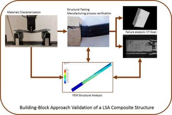
Like any aircraft structure, the Halcon 2 project is designed and manufactured under the “Building-Block Approach,” known as the Pyramid of Tests [3,4]. This design methodology deals with several questions on the comprehension of new structural concepts that are not still fairly answered. As an example, the major causes of in-service damage of composite structures are manufacturing process miscues and low velocity impacts [5,6]. These flaws can promote visible induced damage (BVID), which is the prime source of components debonding, delamination, ply fracture and fiber cracking in composite structures. These failure mechanisms are much more complex than those of conventional metallic materials, leading to new problems for maintenance tasks and repair procedures. Even when numerous analytical, experimental and numerical efforts have been done with the aim to forecast stress, strain and failure mechanics for composite structures, the majority of these studies have been carried out at laboratory scale, where analytic accuracy is still reasonable although budget and infrastructure restrictions [7,8,9,10].
The pyramid of tests deals with five levels of mechanical tests [1]. In the first step, simple coupons are tested in order to obtain basic properties for new and/or modified materials. The second level is conceived to design structural basic elements such as plates, shells, beams and stiffeners. The third level is defined by structural details such as plates with drop-offs, stiffened panels or wing-boxes. The fourth level is dedicated to analyze complete components like a wing, elevator or fuselage. Finally, the fifth level considers testing of the whole aircraft.
The higher the level is accomplished, the bigger the operational and financial risks are taken. Normally, the analysis of singularity details on composite structures, such as ply drop-offs, bolted/fastened/glued joints or edge effects, takes place at the third and fourth levels. At those stages, if a concept or material problem is detected, it is difficult and costly to change the complete design [4].
In the case of the Halcon 2, the key challenge is to manufacture all main components of the aircraft by Vacuum Assisted Resin Infusion (VARI). Other efforts for manufacturing aircraft components in “single step” have become reliable in recent years [11,12,13,14]. Meredith et al. [10] have studied the performance versus cost analysis of carbon fiber reinforced plastics (CRFP), for a specific requirement such as specific energy absorption (SEA). By comparing autoclave versus conventional oven cures, they were found to have identical SEA, providing a cost benefit for massive production. Another example was reported by Verma et al. [11] by analyzing the challenges in a cocured wing test box by vacuum enhanced resin infusion technology (VERITy). They focused on four major technological challenges: 1) selection of materials and optimization of process parameters; 2) design and development of tools; 3) layup of dry layers and assembly preforms; and 4) design of infusion strategy. They concluded the importance of following the Building-Block Approach to get a proper infusion, as well as to improve the numerical tools to evaluate the flow front and to describe the uncertainties associated with complex components. Finally, on the same order of ideas, Komarov et al. [12] evaluated shape distortion during all stages of the vacuum infusion production of composite aerospace structures. They cited that high quality numerical tools (FEA and CFD) for molding products is important for achieving the required accuracy of manufactured products.
Within this framework, the Building-Block Approach is applied to the H2 aircraft as follows. For Level 1, coupon level, a series of test for each material used on the LSA must be done. An extensive materials characterization was performed for obtaining the elastic constants for the composite materials. For Level 2, elements level, performance of sandwich structures is required, since most key elements of the fuselage and wings will use this configuration. These properties have been used in the FEA as input, for taking decisions on the configuration of the different Halcon 2 components and to describe the baseline structural performance. For levels 3 and 4—components and subsystems level—the design of mold and components relies on CFD approaches to calculating the flow front behavior and the resin infusion strategy [13]. Here, surface controls (ailerons, rudder, elevator and flaps) have been manufactured, as well as non-structural components (cowling). Efforts are now devoted to the manufacturing and assembly of the wing and fuselage. Moreover, at Level 5, aircraft level, test frames are now being developed with the goal to perform 1-to-1 scale mechanical tests on the assembled aircraft.
In the present paper, two case studies: 1) cowling and 2) aileron main beam are described to show the engineering processes and the technological challenges encountered in manufacturing high performance-low cost composite structures for Light Sport Aircrafts.

2. Materials and Methods

The main goal of this work is to describe the use of computational and engineering tools for confronting the challenges of manufacturing low cost composite components for a light sport aircraft. It is well known that any aeronautical development must comply with a series of specific stages in order to get an airworthiness certification. These stages are prescribed by the so-called Building-Block Approach [3,4]. After product design, manufacturing processes must be implemented and also validated through experimental tests. Here, two different case studies are shown about the design and verification of the manufacturing processes which is being developed by Horizontec Company. Firstly, it is shown how Computational Fluid Dynamics simulations can be performed to simulate the impregnation process of an aircraft component. The development of simple but consistent CFD models to simulate the VARI process are discussed in the next sections. Also, experimental observations were carried out in order to calculate relevant input parameters for the CFD simulations to increase the reliability of the results. Once the manufacturing process is developed and the component is fabricated, the performance must be validated through mechanical testing. For composite materials, this verification stage is more complex than for traditional materials. Although in the preliminary design and detailed engineering stages, the configuration of materials for each component is determined by computer simulations; the effect of the manufacturing process on the mechanical performance must be studied by means of mechanical tests of each component. The second case study presented in this work shows how it is possible to compare the results from a simple mechanical testing with a computational simulation and use the results of such comparison to verify if the manufacturing process has any effect on the mechanical performance of a structural element of the Light Sport Aircraft.

2.1. Materials

Materials employed for the manufacturing of H2 aircraft are listed in Table 1, Table 2 and Table 3. For the cowling, AS4 Spreadtow carbon fibers by Hexcel® (Seguin, TX, USA) are used. For the aileron main beam, IM7 carbon fibers (unidirectional (UD) and biaxial fabric) by Hexcel® and PVC foam core by 3D Core® (Herford, Germany) are used. In both cases, EPOLAM 2019 epoxy resin by Axson® (San Luis Potosi, Mexico) is employed.

2.2. Manufacturing of CFRP and Sandwich Coupons

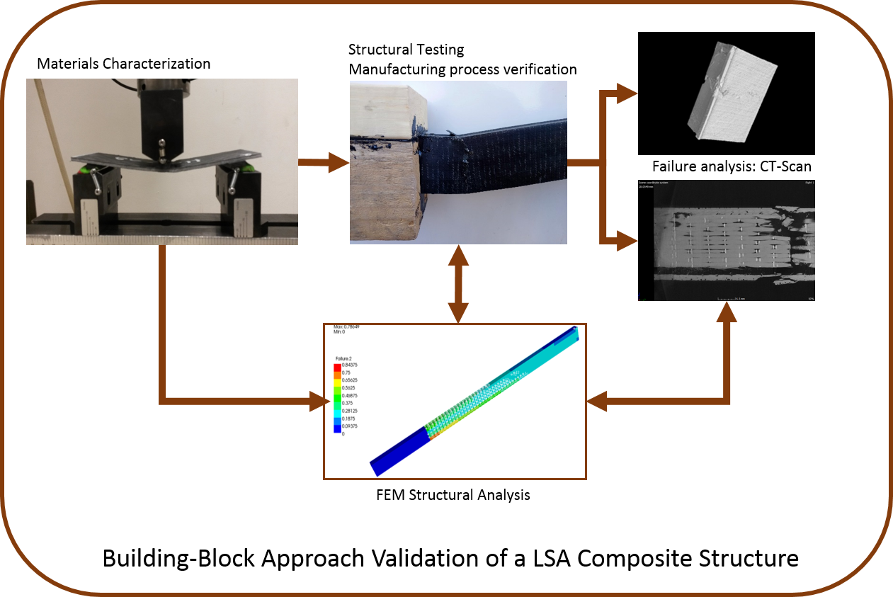
CFRP and sandwich plates are manufactured by Vacuum Assisted Resin Infusion (VARI) (Horizontec-CENTA, Queretaro, Mexico) (Figure 1a). For characterizing AS4 and IM7 CFRP, UD and [±45]4 coupons are employed. For characterizing CFRP-PVC sandwiches, the [02/PVC/02] layout is used.
The vacuum pressure is fixed at 0.25 bar for 2 h, till gelation of the resin is evident. The polymerization reaction takes place for 16 h at 25 °C. For the CFRP, post-curing of 2 h at 60 °C, then 2 h at 80 °C and finally 4 h at 100 °C, following the recommended recipe by Axson® (Figure 1b) [17]. Sandwich structures were post-cured for 2 h at 60 °C [17].

2.3. Mechanical Characterization of CFRP and Sandwich Coupons

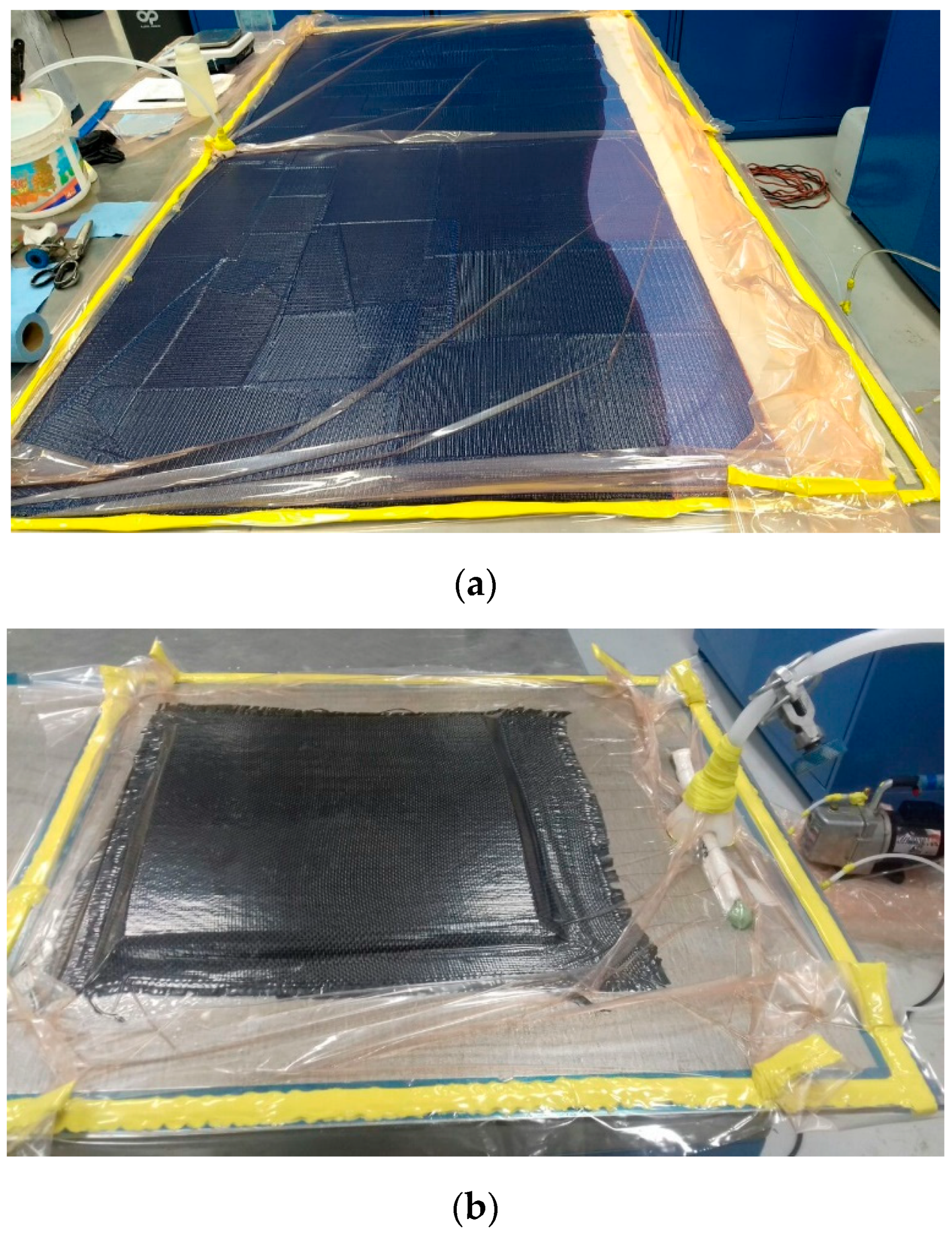
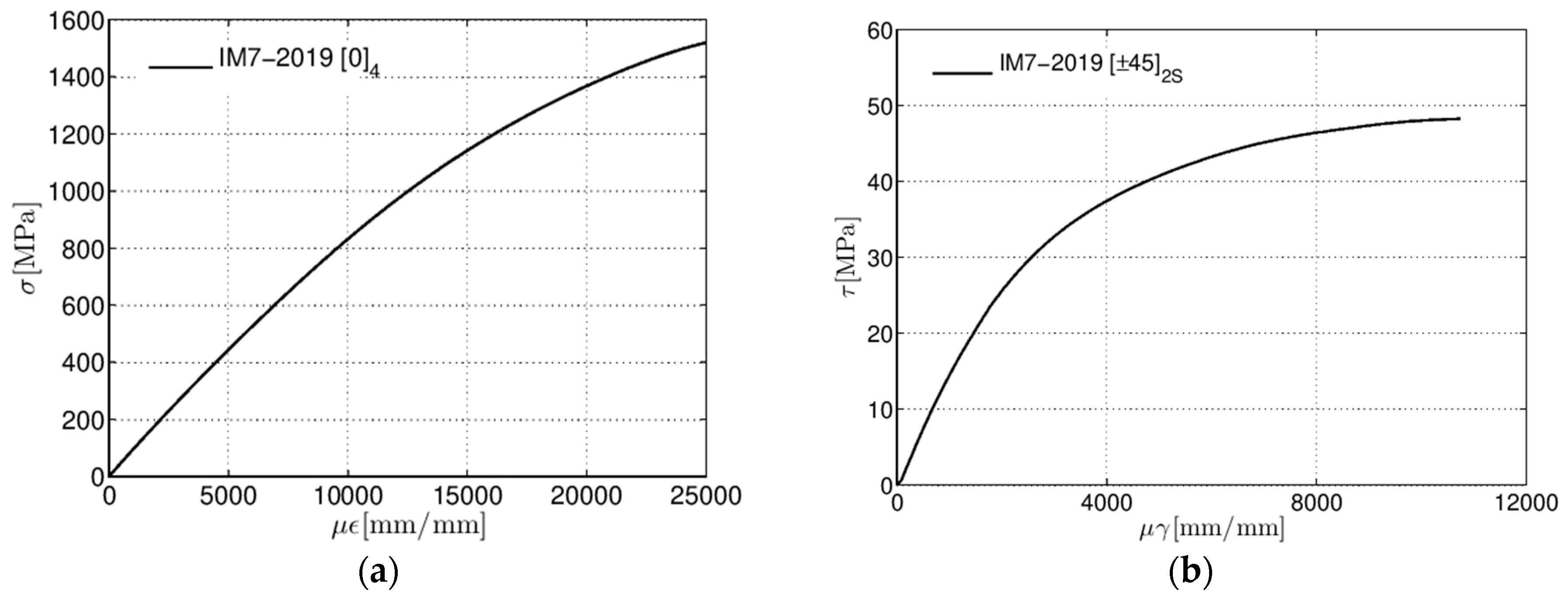
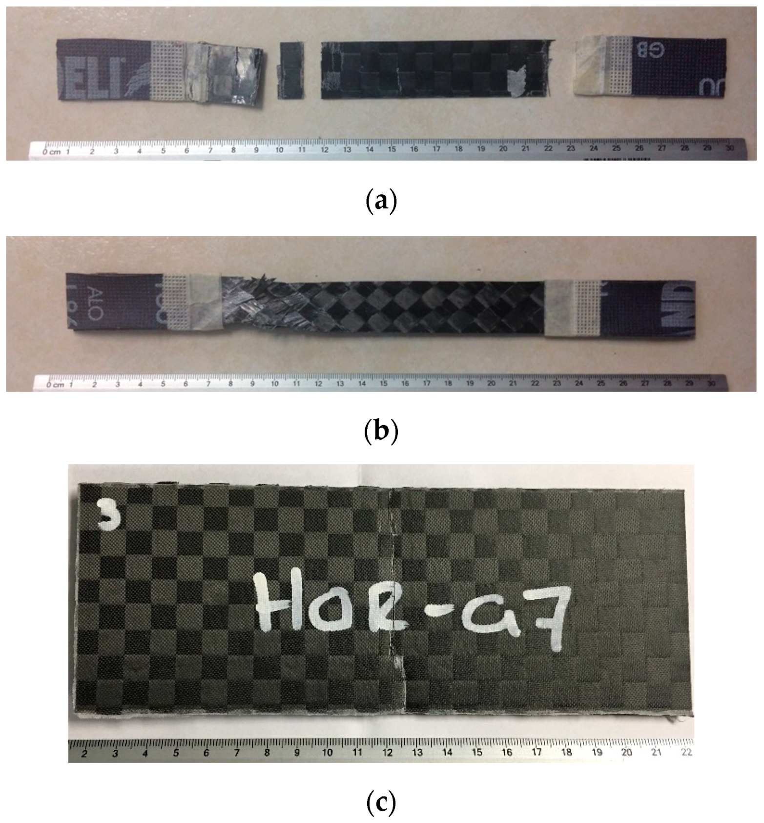
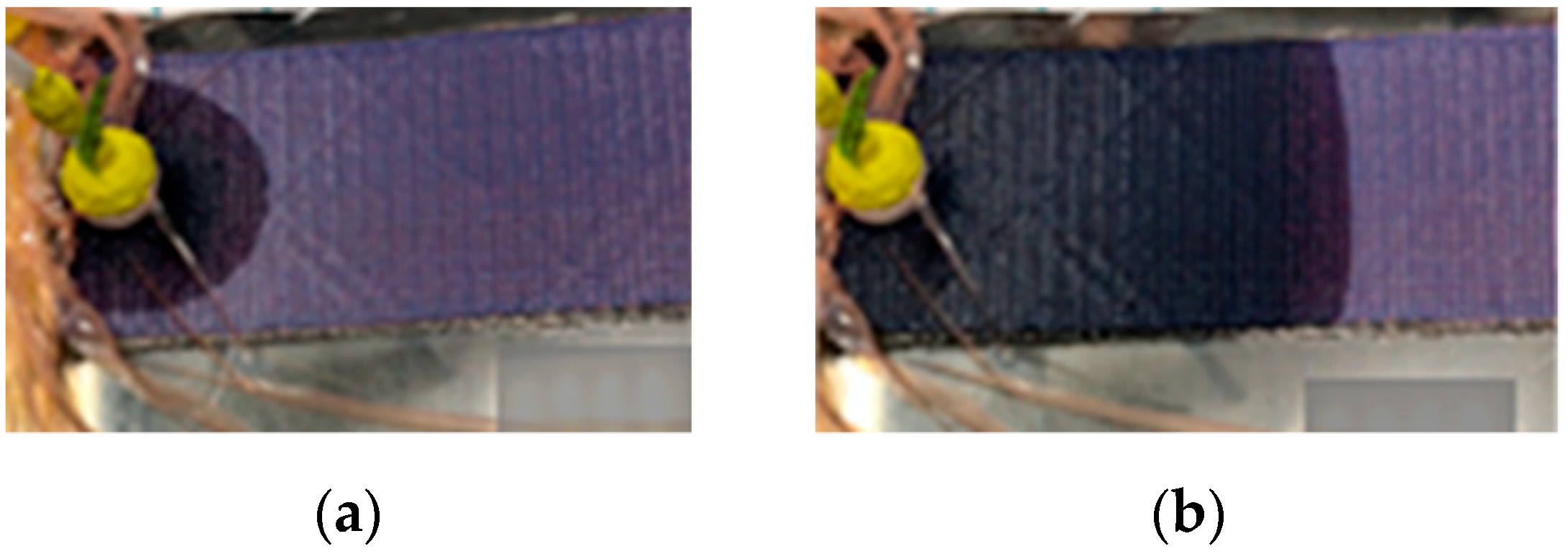
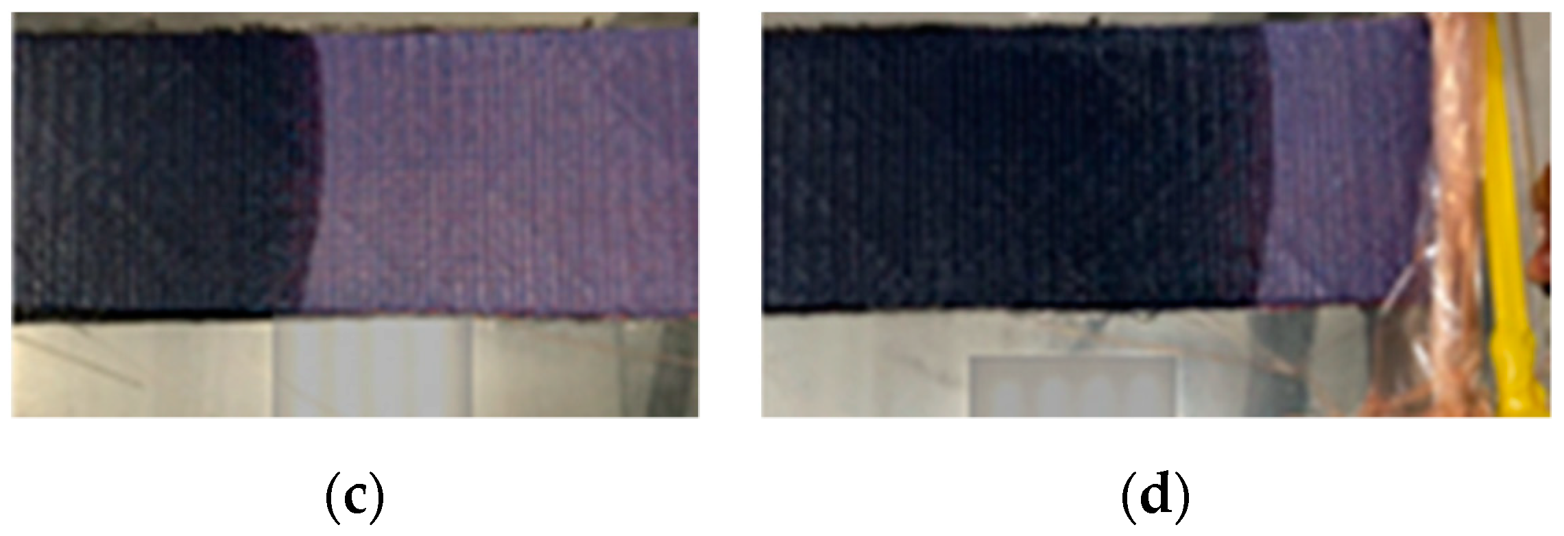
For the CFRP, mechanical characterization was carried out following ASTM D3039 and ASTM D3518 standards [19,20]. Nominal dimensions for the carbon-epoxy coupons were 250 × 25 × 1 mm with a testing zone restricted to 150 mm. All specimens were instrumented with strain gauges at the surface. For tabs, 60 grain gridding paper was used. For the tensile tests, MTS Insight 100kN Universal Testing Machine (CENTA, Queretaro, Mexico) was employed. The crosshead rate was set to 1mm/min until coupon failure is reached (Figure 2a).
For the CFRP-PVC sandwich, flexural tests according to ASTM C393 standard [21] were performed. Nominal dimensions for the sandwich were 200 × 75 mm. The average thickness for the sandwich samples was 3.5 mm. The span length was fixed in 150 mm. For the flexural tests, an Instron 8872 Servohydraulic Testing Machine (CENTA, Queretaro, Mexico) was employed. The crosshead rate was set to 6mm/min until the coupon failure is reached (Figure 2b).

2.4. CFD Modeling for the Impregnation Process of the Aircraft Upper Cowling

The quality of any composite component manufactured by VARI process depends strongly on the impregnation stage. During this stage, the resin flows through the preforms of carbon fiber and the pores must be fully filled by the resin in order to avoid defects in the final product. In this case study, we present the implementation of CFD simulations to compute the global behavior of the resin flow, estimate the filling time of the component and verify if the resin inlet and outlet gates are appropriate to carry out the VARI process. For this purpose, the analysis of the resin flow through the upper cowling of a light sport aircraft is developed. In recent years, CFD models to predict the resin flow through different technical fabrics have been studied in order to use them as a manufacturing process design tool, for instance [22,23,24]. There are multiscale models that can take into account different effects during the resin impregnation stage, however, as an engineering tool, the CFD models must be as simple as possible in order to be used for testing different configurations of the VARI process and selecting the impregnation strategy for manufacturing the component.
The CFD model for the resin flow through the cowling fibers preform is based on the solution of the porous media equations in ANSYS Fluent. The Volume-of-Fluid (VOF) technique was implemented in order to solve the equations for a two-phase flow (air-resin) including the interface and to track the advance of the resin front as a function of time [
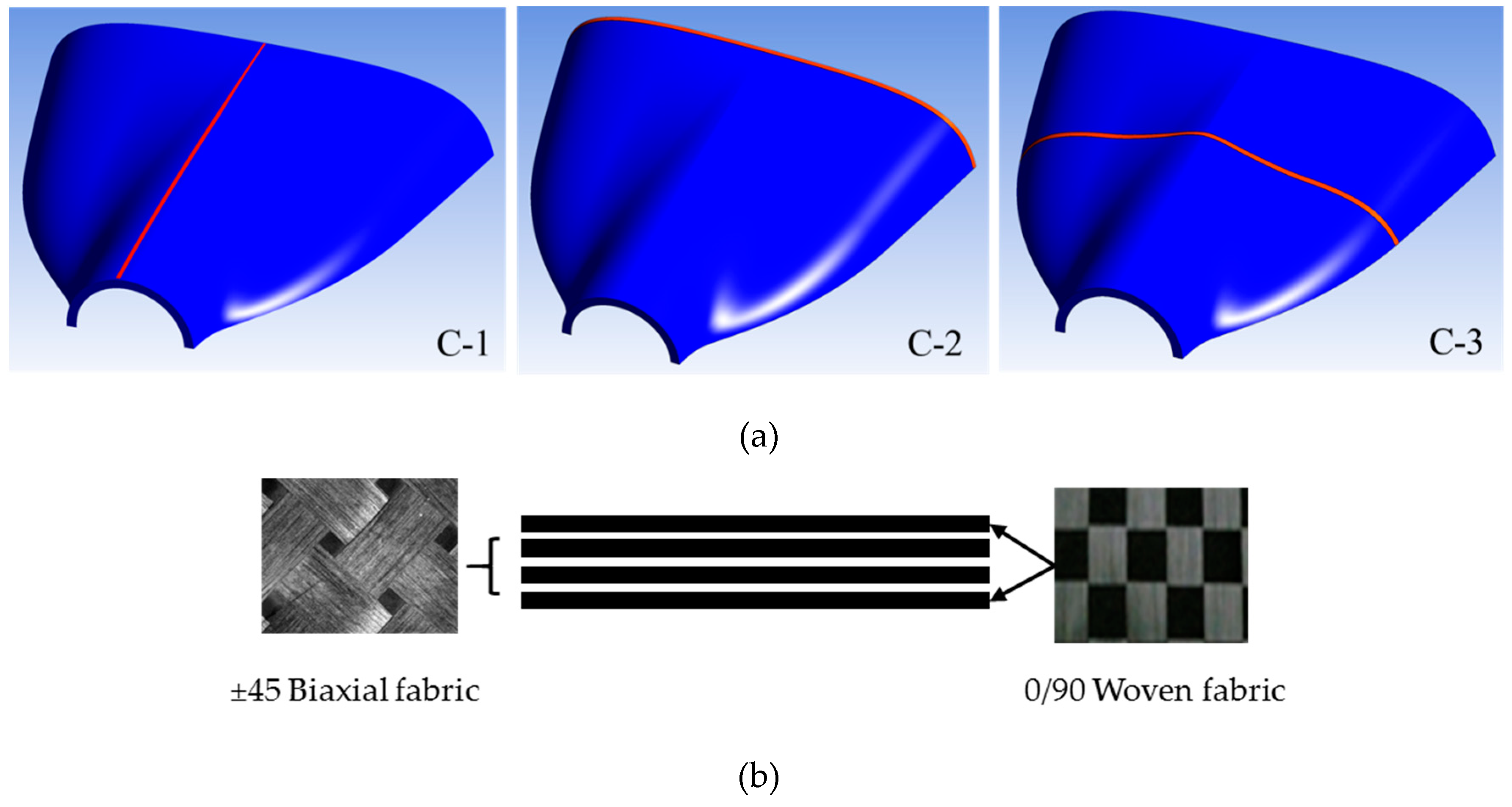
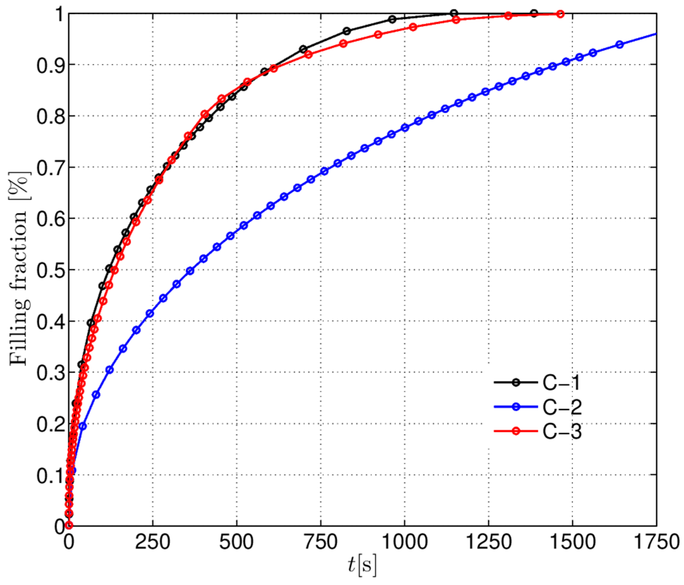
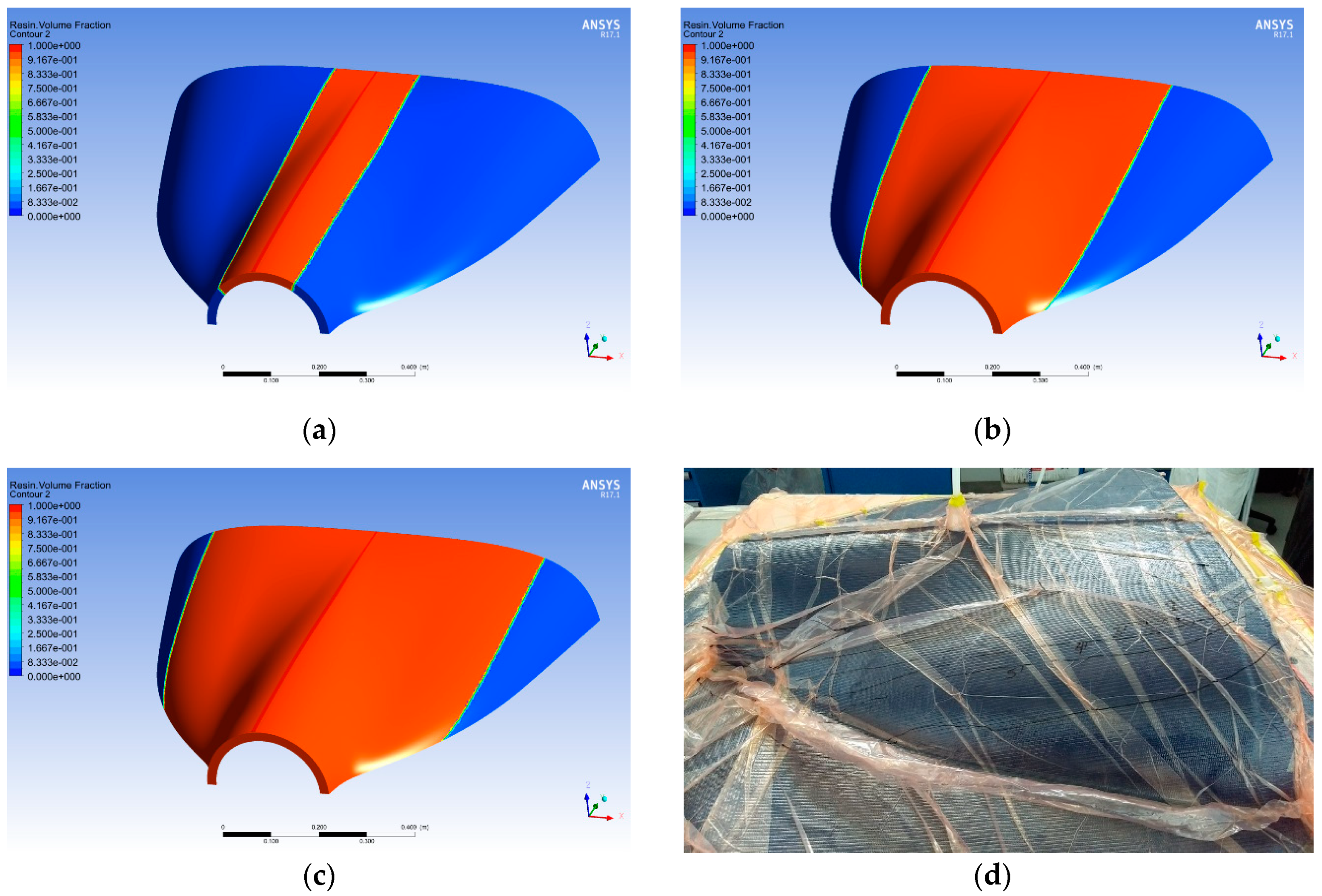
25]. An unstructured tetrahedral mesh was built to discretize the conservation equations. The time step was adjusted throughout the simulation in order to obtain a Courant number less than 1 during the entire simulation. The boundary conditions implemented in the model were based on the vacuum pressure that the company has fixed for its VARI processes. The geometry of the aircraft upper cowling is shown in Figure 3a. Three different configurations for the inlet and outlet gates were simulated, C-1, C-2 and C-3. The inlet gate for each case is plotted in red color in Figure 3a, the resin outlet was simulated in the lateral edges of the cowling. The laminate code for manufacturing the upper cowling is shown in Figure 3b.
The critical part for simulations of these kinds of flows is the calculation of the porosity and permeability of the preform laminate configuration. As was commented, since in the CFD model the preforms are solved as a porous medium, the porosity and permeability tensor must be incorporated into the numerical model. The porosity of the medium can be found through fiber volume fraction experiments for individual layer specimens of each kind of fiber that comprises the laminate. Once the porosity of each ply is calculated, the effective porosity of the laminate is computed as an average of the porosity of the individual layers weighted by their thickness.
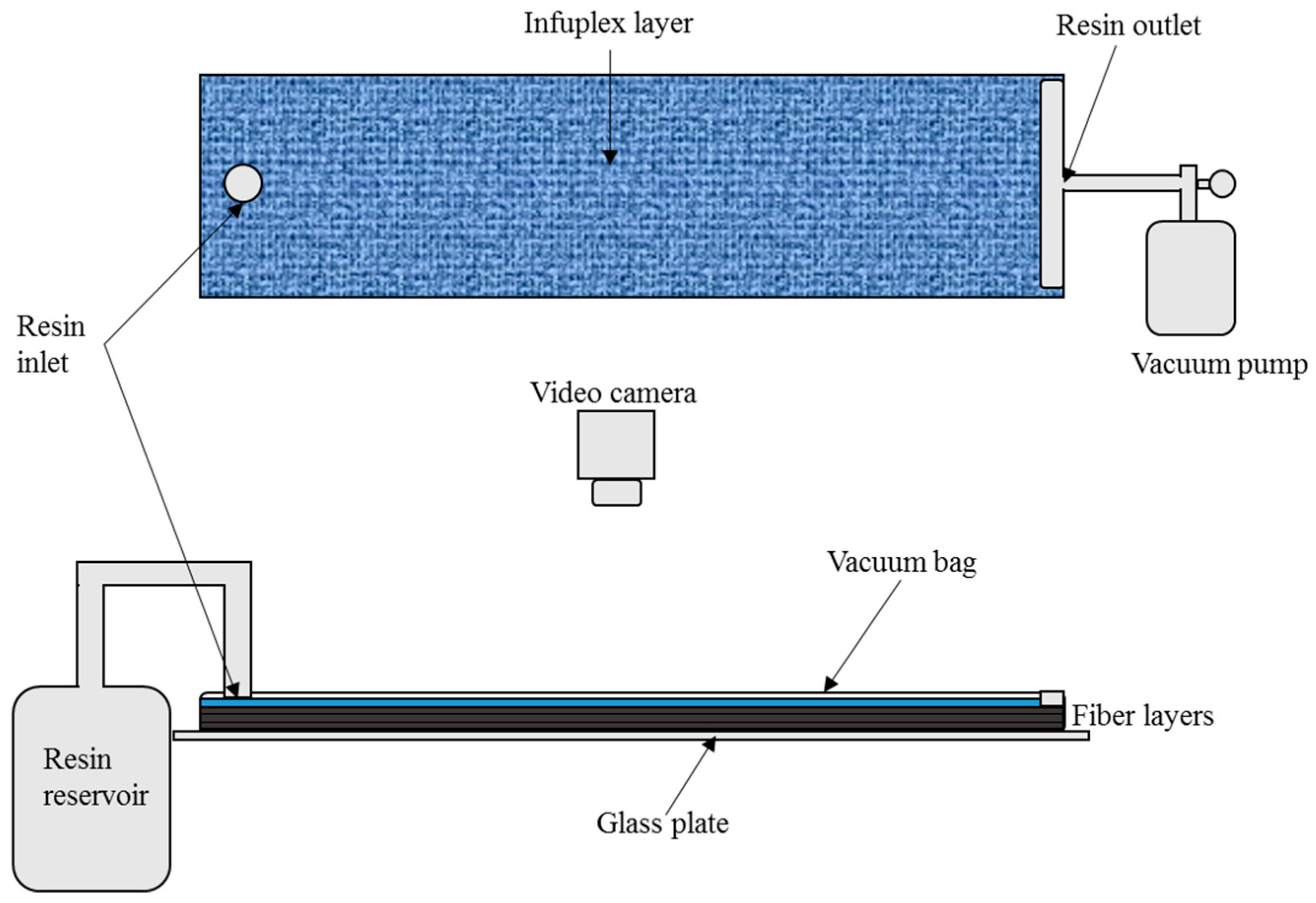
The permeability tensor is very difficult to compute; almost all the simulations reported in the literature are solved using the permeability found through theoretical models or experimental observations. The theoretical models to compute the permeability using the geometrical characteristics of the fiber have been developed to provide this information to numerical simulations; however, the permeability depends in many parameters that involves the geometrical features but also the fluid that moves through the porous medium. As a result, the models reported do not predict accurately the permeability of a laminate. In this work, experimental observations were carried out to estimate the permeability of each individual ply of the laminate. Once the individual permeability was calculated, the effect permeability of the preform was computed by averaging the individual values. The experiments used to calculate the effective permeability of the porous medium are based on a vacuum assisted resin transfer (VARTM) setup as shown in Figure 4 [26]. The rigid part of the mold is made from a rectangular 1.2 × 1.5 × 0.01 m3 glass plate on which preforms up to 0.2 × 1 m2 in area were laid up. Given the high degree of repeatability that can be achieved, a linear channel flow experiment driven by a constant pressure gradient was chosen for the measurement of permeability [23]. Moreover, the preform width was chosen to be about 16 times the inlet hose diameter. In this manner, good practices for permeability measurement are observed [27].
The mold and preform preparation proceeded as follows. First, the glass plate was treated with mold cleaning (acetone) and release agents (demolding wax). Next, carbon fiber fabrics were cut to 0.1 × 0.9 m2 and laid up on the glass. An infuplex layer (high permeability layer, HPL) was placed on top of the carbon fiber fabrics in order to promote a uniform resin flow along the laminate. Afterwards, a point injection source and a linear sink were placed on the glass plate in such a manner that the resin would flow along the longest preform dimension. After the vacuum bag was placed and sealed, the linear sink and the injection source were connected to the vacuum pump and resin reservoir, respectively. Finally, a digital video camera was mounted above the glass plate to monitor the flow front progression with time. The vacuum pump maintained a pressure of 3.07 kPa throughout the resin transfer process. The results obtained are shown in the following section.

2.5. Experimental Test and FEM Simulation for Aileron Main Beam

For structural elements of the aircraft components, it is mandatory to verify the manufacturing process and then the quality of each element. Following the ASTM standards applicable for this kind of aircraft, a road map of the experimental tests for the elements of the structural components was developed [
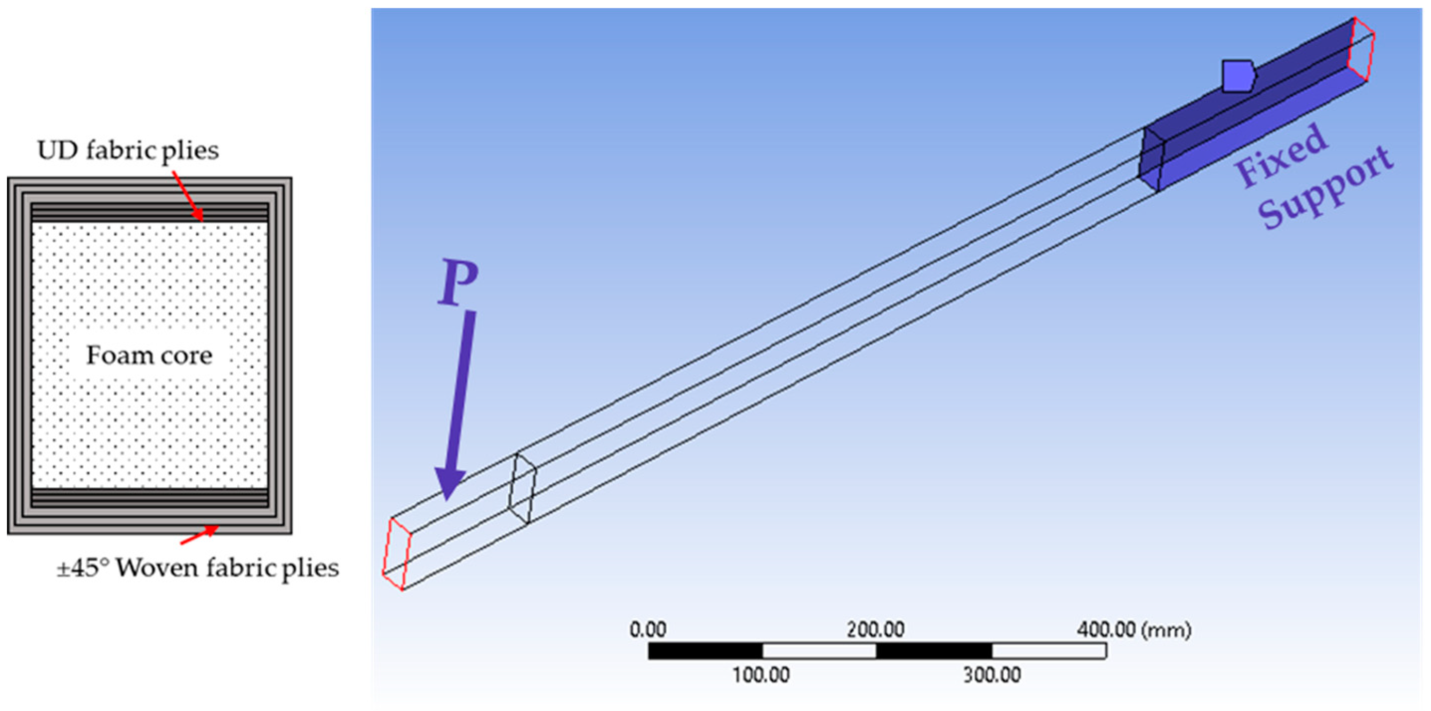
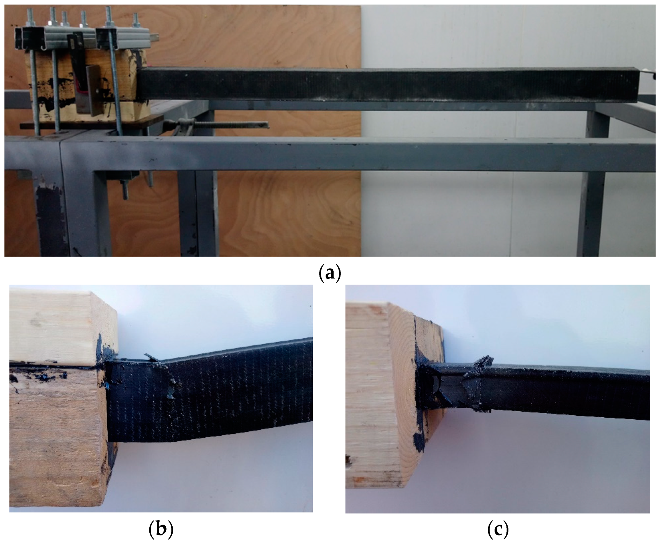
2]. The first structural component manufactured was the aileron and as it is well known, the critical element of this component is the main beam. The beam was designed with a rectangular cross-section using two different fiber fabrics and a foam core. In Figure 5, the materials configuration and the cross-section of the beam are shown. The layout configuration for the aileron beam consists in a central PVC foam core, three unidirectional layers in each beam flange (top and bottom) and two [±45] fabrics around them.
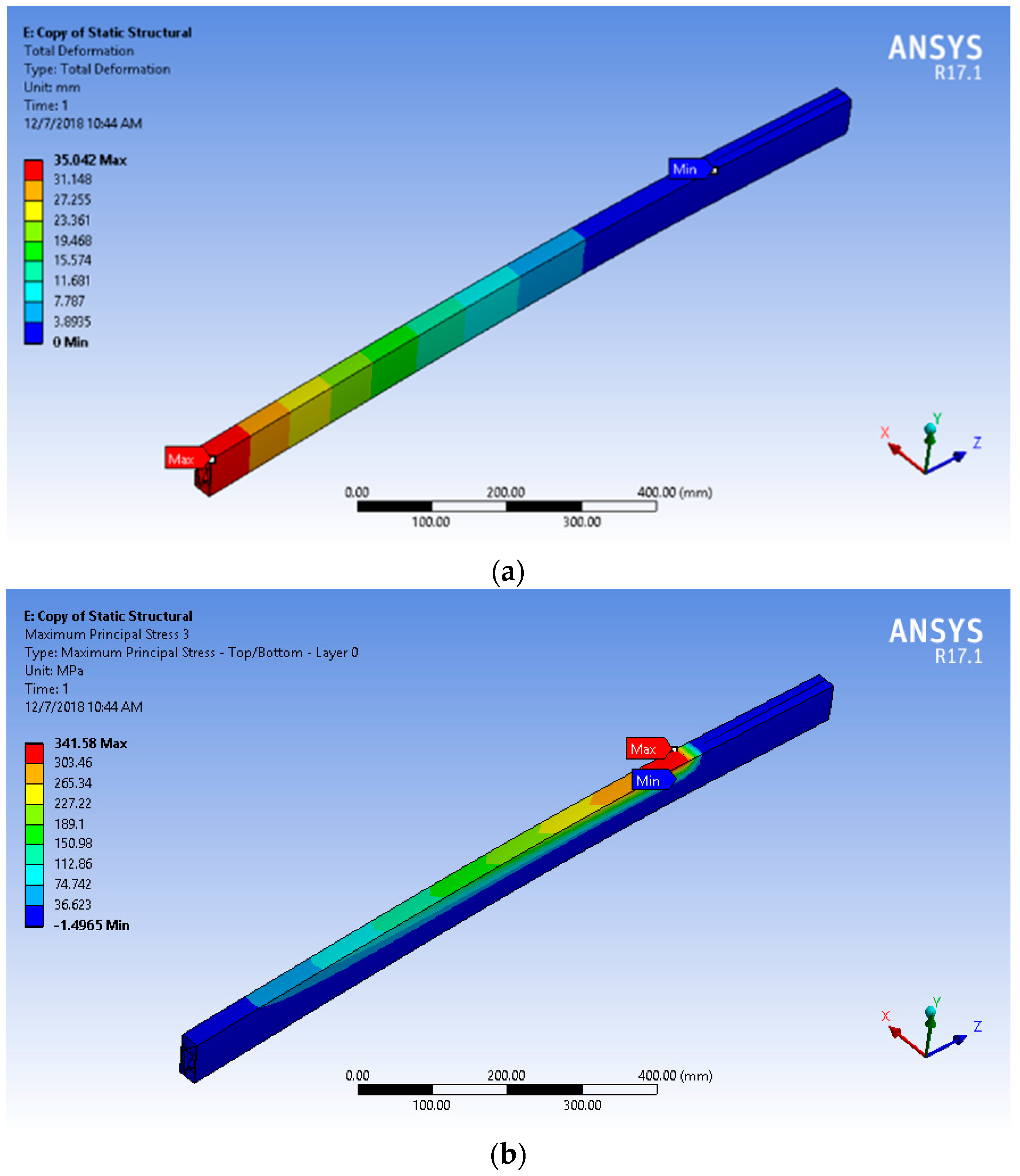
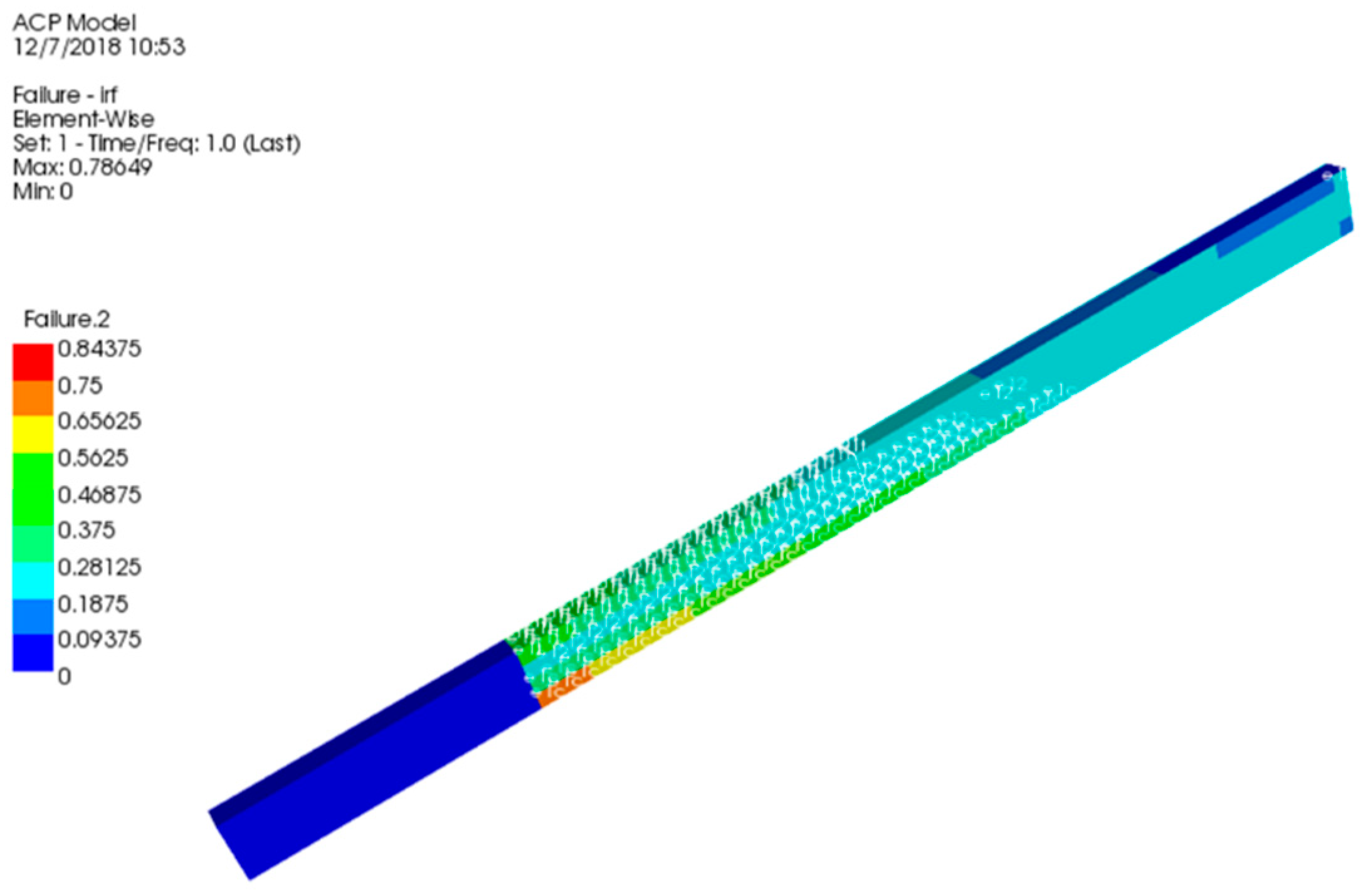
The performance of the aileron main beam was evaluated in cantilever conditions and the results were compared with the ones predicted by a Finite Element Method (FEM) simulation (CENTA, Queretaro, Mexico). The experimental test consisted of a fixed cantilever beam and an applied localized load, P, which was increased until the beam failed. The FEM simulation was implemented using ANSYS ACP utilizing the mechanical properties obtained from the level 1 tests. A total mesh of 8640 elements was constructed for the fiber-core assembly. Shell type elements were used for fiber layers and Solid type elements for the PVC foam core.

3. Results

3.1. Mechanical Testing for Materials Characterization

Mechanical characterization for both CFRP and CFRP-PVC sandwiches will provide the elastic properties to evaluate the performance of structural components for the H2 aircraft. The elastic properties of the CFRP and CFRP-PVC foam core sandwich are given in Table 4, Table 5, Table 6 and Table 7.
For all CFRP coupons, the coordinate systems referred is the following: x: direction of the tensile load, y: transverse direction of the tensile load and z: through-the-thickness direction of the laminate. Young’s Modulus was calculated by using the chord modulus equation in the linear portion of the stress-strain curve, between 1000 με and 3000 με [19]. Shear Modulus was calculated using the chord modulus equation in the linear portion of the stress-strain curve, below 4000 με [20].
For the sandwich coupons, the coordinate systems referred is the following: x: direction of the sandwich span, y: direction of the sandwich width and z: through-the-thickness direction of the sandwich. Core shear ultimate strength and facing stress were calculated by using the proper equations of the ASTM C393 standard [21].
Figure 6 shows the IM7/EPOLAM 2019 CFRP stress-strain curves from tensile test following ASTM D3039 standard. As expected, on one side, stress-strain curves for UD coupons show a linear elastic behavior at the beginning of the plots, below 6000 με, where mechanical properties are calculated (Figure 6a). Nonetheless, above 10,000 με, the material exhibits a notable elastoplastic behavior, prior to failure. On the other side, stress-strain curves for [±45]2s coupons, above 3000 με, exhibit a more evident elastoplastic behavior (Figure 6b).
On one hand, the failure mode for UD and biaxial coupons is on sudden fracture type LGV (Lateral, Gage, Various, Figure 7a). The fracture was explosive, where most of the CFRP fragments fell down inside the protection chamber. On the other hand, failure mode for [±45] coupons is warp-weft sliding, type SGT (Splitting, Gage, Top, Figure 7b). Both failure modes are according to typical codes of ASTM D3039. The failure mode for the CFRP sandwich with PVC core was in the compressed facing type FGT (Facing failure, Gage, Top facing, Figure 7c), with barely visible core crushing.

3.2. Cowling Impregnation Process

Before the CFD implementation, the permeability characterization was performed for the laminate configuration selected for manufacturing the upper cowling of the aircraft. Using the experimental setup described in Section 2.1, analysis of resin flow through each type of fiber was carried out. An image processing algorithm was used to compute the advance of the front as a function of time. Knowing the pressure gradient and the viscosity of the resin, the permeability of the fiber was calculated through the integration of the Darcy’s Law [28]. The same procedure is being implemented for all the components of the Light Sport Aircraft, so that the experiments to characterize the resin flow through the fiber selected to manufacture each component of the aircraft were performed through this kind of observations. In Figure 8, one can see the resin front advance as function of time for the ±45 biaxial fiber. At the beginning of the impregnation process, a radial flow is developed through the carbon fiber plies according to the point source configuration in the injection gate. However, the lateral boundary constraints force the radial flow to evolve into a linear flow in about 90 seconds. From that point and until the fiber laminate is totally impregnated by resin, the flow advance is linear and a Darcy Law in one direction can be applied to compute the permeability.
Once the permeability of each ply of the laminate was determined, the average effective permeability and porosity were calculated for being included as an input parameter of the CFD model. The effective permeability resulting from the experiments for the cowling laminate was keff = 3.8641 × 10⁻¹². The details with respect to the permeability calculation from the experiments for each ply of the laminate can be found in Reference [26]. Fiber volume fraction tests were performed for each ply of the laminate in order to compute the porosity. The effective porosity of the laminate was calculated as the average porosity weighted with the thickness of each ply, resulting equal to ϕeff = 0.479. The filling process simulation were carried out for the three configurations C-1, C-2 and C-3, presented in Figure 3. In order to analyze quantitatively the filling process of the component, the integral of the resin volume fraction as function of time was computed during the simulations and is plotted in Figure 9 for the three configurations. The curves of the resin volume fraction can give relevant information about the evolution of the impregnation process. As can be observed, with the C-1 configuration the cowling fills faster than with the others. The filling process with C-2 configuration lasts much more time that the C-1 and C-2 and after 1750 s in the simulation, the cowling was not completely filled of resin. On the other hand, the resin volume fraction as a function of time behaves in a very similar way to the beginning of the process for C-1 and C-3 configurations, however, in the final part of the process, the resin impregnation of the preform slows down in C-3 with regarding C-1. From this information, the C-1 configuration can be considered the best choice in order to minimize the filling time. For this configuration, the resin flows and fills around 40% of the component very quickly until the flow considerably slows down due to the pressure balance inside the porous medium.
In Figure 10, the filling process of the upper cowling is shown, through the contour map of the resin volume fraction for C-1 configuration. As it can be appreciated, the resin flows very fast at the beginning of the process and the velocity of the resin front decreases as the preform is filled. The results of the simulation shows that using this configuration, the component fills uniformly and symmetrically with respect to its longitudinal axis. The total filling time for the component was about 1180 s. In Figure 10d, the VARI process implemented in the laboratory for the cowling using the C-1 configuration is shown, it is important to highlight that the component successfully manufactured with good surface quality results.

3.3. Verification of the Manufacturing Process of the Aileron Main Beam

For level 4 structural testing, mechanical tests of an aileron main beam were carried out. Master mold of aileron main beam was fabricated with MDF by CNC machining. After that a composite mold using twill carbon fiber and EPOLAM 2019 was fabricated. Manufacturing process of the aileron main beam follows the same VARI procedure described in Section 2.2. Layout of the beam is the same as described in Section 2.5. Post-curing for 2 h at 60 °C was the same as the sandwich coupons [17].
The manufacturing processes of the aileron main beam of the light sport aircraft were verified by comparison between the mechanical performances exhibited in testing and the results obtained from the FEM simulation. In Figure 11a, the experimental set up for the cantilever beam test of the aileron main beam is shown. The beam was fixed at one end and loaded at the opposite end. Load was applied manually by using sand bags. The beam was instrumented with two strain gauges at the fixed end in the upper and bottom surface respectively. Load was applied till the beam failure was reached.
The maximum deflection of the beam exhibited at the free edge in the experiment was 34 mm. The beam failed with a load of 35 kg. As can be observed in Figure 11b,c, the beam failed close to the fixed constraint. The results from the computational simulation showed a similar qualitative behavior respect the experimental test. The simulation was performed imposing a load of 343.35 N (35 kg) showing a maximum deformation of 35.02 mm (Figure 12a). With this deformation, the maximum value of the principal stress σ1 is placed at the same position as the failure occurred during the mechanical testing (see Figure 12b). In Figure 13, the maximum strain failure criterion is plotted, as it is displayed, the maximum value of the failure criterion is 0.8437, indicating that the beam is able to support this load. However, the mechanical test showed the failure of the beam at these load conditions. The lack in the performance of the beam can be attributed to the intrinsic errors during the manufacturing process. As reported in literature [29], stiffened structure commonly fails at components interface. For woven composites, warp-weft sliding, fabric distortion and fiber decohesion are expected. In the case of sandwich structures, core crushing and compressed facing are also expected mainly for compression-tension stress state. For the aileron main beam, deflection due to the aerodynamic forces is expected, therefore, attention on fiber crushing and core crushing on the compression face shall be avoided.
In order to visualize in detail the internal structure of the beam and capture the manufacturing miscues, a computerized tomography analysis (CT-Scan) was carried out. In Figure 14b, the results from the three-dimensional reconstruction of the beam using the CT-Scan equipment are shown. A lateral and top slices at the middle planes of the beam structure are presented in Figure 14a. It can be seen the hexagonal PVC foam core on the left and the top and bottom fiber layers on the right side. The presence of pores is easily identified in the fibers and the hexagonal PVC foam core, the lack of resin in those zones can promote the premature failure of the beam with respect to the results obtained from the FEM simulation. In Figure 14c, a top slice at one of the UD fiber layer is shown, the pores and the fracture path in this fiber layer can be observed.

4. Discussion and Conclusions

The manufacturing process development and validation for components of a light sport aircraft were presented. The VARI process was chosen to fabricate the composite components of the Horizontec aircraft to reduce the manufacturing cost versus an autoclave or RTM procedure [10,30,
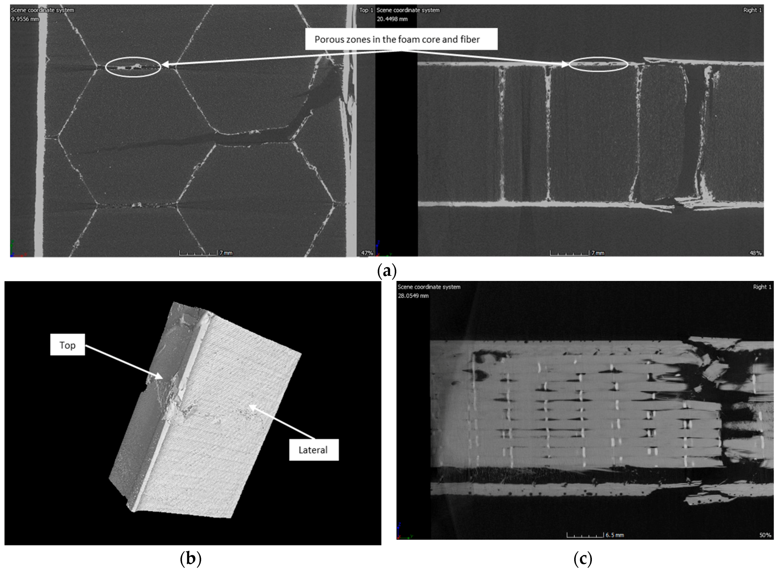
31]. The cost analysis of the VARI process was carried out by Horizontec when the project requirements were stablished. In order to show how the engineering and computational tools are utilized during the development of these manufacturing processes, two cases of study were presented. Firstly, the impregnation stage was analyzed for the upper cowling using CFD simulations. For this purpose, the permeability of the fibers was characterized to be used as input parameters of the simulation. CFD model was performed and the transient behavior of the resin flow during the filling process was computed. It is important to highlight that the CFD model was developed as simple as possible in order to reduce the computational time. It is expected to compute the global features of the flow and use these kind of CFD models as a fast engineering tool to design the impregnation strategy for each component of the aircraft. Here, three different inlet-outlet configurations to perform the impregnation process for the upper cowling were analyzed. From the simulations results, the filling time for each configuration was computed through the calculation of the resin volume fraction as a function of time. Then, the inlet-outlet configuration was selected in order to reduce the filling process. It is important to mention that with this model, it could be possible to propose a pressure or flow rate control methods to optimize the impregnation process. As a second case study, the mechanical testing and computational simulation for the aileron main beam was presented. Once the component is fabricated and in order to validate the manufacturing process, the component was tested and its mechanical performance was compared with results obtained from FEM simulation under the same load conditions. In order to develop robust simulations and model as well as possible the mechanical behavior of the aileron main beam before implementing the FEM simulation, the composite materials were characterized through coupons mechanical testing to feed the FEM simulation with the measured material properties. It was shown that for the case of the aileron beam manufactured by VARI process and in cantilever beam scenario, the beam has a performance of 85% with respect to the simulation results. Since all the mechanical properties for the corresponding materials were included into the FEM model and from the porosity zones identified from the CT-Scan analysis, it can be concluded that the 15% difference in performance is due to manufacturing errors.
For manufacturing LSA, the Building-Block Approach describes an excellent path for validating aircraft components. In both cases, cowling and aileron main beam, elastic properties of carbon fiber based structures were determined and fulfill the materials requirements according to LSA standards. The implementation of sandwich structures for both cases solves economic and engineering constraints. However, components must meet 1-to-1 scale mechanical tests to assure the certification type of Halcon 2 aircraft.

Author Contributions

Conceptualization, G.A. and M.T.; methodology, M.T., S.P., S.L. and C.A.E.-V.; software, S.P. and S.L.; validation, M.T. and S.L.; formal analysis, S.P., M.T. and S.L.; investigation, M.T., S.P., S.L. and C.A.E.-V.; resources, G.A. and M.T.; data curation, M.T. and C.A.E.-V.; Writing—Original Draft preparation, S.P., M.T. and S.L.; Writing—Review and Editing, M.T. and S.P.; visualization, S.P. and S.L.; supervision, G.A.; project administration, M.T. and G.A.; funding acquisition, G.A.

Funding

This research was funded by the Nacional Council of Science and Technology of Mexico (CONACYT) and the Ministry of Economy of Mexico (SE) through the Technological Innovation Fund (FIT), grant number ECO-2015-C01-260587. Experimental characterization was funded by CONACYT through the Research Fund for the Development of Space Activities (FIDAE), grant number 275783.

Acknowledgments

Mauricio Torres, Saul Piedra and Carlos A. Escalante-Velázquez convey their special appreciation to the “CONACYT Research Fellow Program (Cátedras CONACYT).” All of the authors convey their appreciation to Aaron Burgos, Miguel Vergara, Ricardo Lozada and Rodrigo Pérez for their technical support, as well as, Marco Paredes and Marc Emile Preud’homme from the CENTA NDT Laboratory.

Conflicts of Interest

The authors declare no conflict of interest.

References

  1. DGAC CO AV-27/12. Mexican mandatory circular for technical requirement regulation for ultralight and experimental aircrafts to obtain an approval and technical requirement regulation for light sport aircraft to obtain a certification. In Dirección General de Aeronáutica Civil; SCT: Mexico City, Mexico, 2012. [Google Scholar]
  2. ASTM F2245-16c. Standard Specification for Design and Performance of a Light Sport Airplane; American Society for Testing and Materials International: Philadelphia, PA, USA, 2016. [Google Scholar]
  3. Baker, A.; Dutton, S.; Kelly, D. Aircraft applications and design issues. In Composite Materials for Aircraft Structures, 2nd ed.; Schetz, J.A., Ed.; AIAA Education Series: Washington, DC, USA, 2004; pp. 435–475. ISBN 1-56347-540-5. [Google Scholar]
  4. Rouse, M.; Jegley, D.C.; McGowan, D.M.; Bush, H.G.; Waters, W.A. Utilization of the Building-Block Approach in Structural Mechanics Research; NASA: Greenbelt, CA, USA, 2005; pp. 105–116.
  5. Park, J.; Ha, S.; Chang, F.K. Monitoring impact events using a system-identification method. AIAA J. 2009, 47, 25–36. [Google Scholar] [CrossRef]
  6. McCarthy, C.T.; Gray, P.J. An analytical model for the prediction of load distribution in highly torque multi-bolt composite joints. Compos. Struct. 2010, 93, 17–27. [Google Scholar]
  7. Crouzeix, L.; Davila, Y.; Collombet, F.; Douchin, B.; Grunevald, Y.H.; Zitoune, R.; Cénac, F. Study of double step lap composite repairs on CFRP evaluators. In Proceedings of the 15th European Conference on Composite Materials, Venice, Italy, 24–28 June 2012. [Google Scholar]
  8. Lamkanfi, E.; Van Paepegem, W.; Degrieck, J. Shape optimization of a cruciform geometry for biaxial testing of polymers. Polym. Test. 2014, 41, 7–16. [Google Scholar] [CrossRef]
  9. Torres, M.; Crouzeix, L.; Collombet, F.; Douchin, B.; Grunevald, Y.H. Numerical and experimental value added of multi-instrumented technological evaluator for the analysis of thick monolithic composite structures with singularity details. Compos. Struct. 2015, 127, 41–50. [Google Scholar] [CrossRef]
  10. Meredith, J.; Bolson, E.; Powe, R.; Collings, E.; Kirwan, K. A performance versus cost analysis of prepreg carbon fiber epoxy energy absorption structures. Compos. Struct. 2015, 124, 206–213. [Google Scholar] [CrossRef]
  11. Verma, K.K.; Dinesh, B.L.; Singh, K.; Gaddikeri, K.M.; Sundaram, R. Challenges in processing of a cocured wing test box using vacuum enhanced resin infusion technology (VERITy). Procedia Mater. Sci. 2014, 6, 331–340. [Google Scholar] [CrossRef]
  12. Komarov, V.A.; Kurkin, E.I.; Spirina, M.O. Composite aerospace structures shape distortion during all stages of vacuum infusion production. Procedia Eng. 2017, 185, 39–145. [Google Scholar] [CrossRef]
  13. Romano, F.; Barile, M.; Cacciapuoti, G.; Godard, J.L.; Vollaro, P.; Barabinot, P. Advanced OoA and automated technologies for manufacturing a composite outer wing box. MATEC Web Conf. 2018, 5, 1–8. [Google Scholar] [CrossRef]
  14. Brouwer, W.D.; Van Herpt, E.C.; Labordus, M. Vacuum injection moulding for large structural applications. Compos. Part A 2003, 34, 551–558. [Google Scholar] [CrossRef]
  15. HexTow® AS4 Carbon Fiber. In Product Data Sheet; Hexcel Corporation: Seguin, TX, USA, 2018; pp. 1–2.
  16. HexTow® IM7 Carbon Fiber. In Product Data Sheet; Hexcel Corporation: Seguin, TX, USA, 2018; pp. 1–2.
  17. EPOLAM 2019, Epoxy laminating system by infusion. In Product Data Sheet; Axson Technologies Head Office France: Saint Ouen L’Aumone, France, 2018; pp. 1–2.
  18. PVC and XPS foam cores. In Product Data Sheet; 3D Core TM: Herford, Germany, 2018; pp. 1–2.
  19. ASTM D3039. Standard Test Method for Tensile Properties of Polymer Matrix Composite Materials; ASTM International: West Conshohocken, PA, USA, 2014. [Google Scholar]
  20. ASTM D3718. Standard Test Method for In-Plane Shear Response of Polymer Matrix Composite Materials by Tensile Test of a ±45° Laminate; ASTM International: West Conshohocken, PA, USA, 2013. [Google Scholar]
  21. ASTM C393. Standard Test Method for Core Shear Properties of Sandwich Constructions by Beam Flexure; ASTM International: West Conshohocken, PA, USA, 2016. [Google Scholar]
  22. Kang, M.K.; Jung, J.J.; Lee, W.I. Analysis of resin transfer moulding process with controlled multiple gates resin injection. Compos. Part A 2000, 31, 407–422. [Google Scholar] [CrossRef]
  23. Trochu, F.; Ruiz, E.; Achim, V.; Soukane, S. Advanced numerical simulation of liquid composite molding for process analysis and optimization. Compos. Part A 2006, 37, 890–902. [Google Scholar] [CrossRef]
  24. Laurenzi, S.; Grilli, A.; Pinna, M.; Nicola, F.; Cattaneo, G.; Marchetti, M. Process simulation for a large composite aeronautic beam by resin transfer molding. Compos. Part B 2014, 57, 47–55. [Google Scholar] [CrossRef]
  25. Tryggvason, G.; Scardovelli, R.; Zaleski, S. Direct Numerical Simulations of Gas-Liquid Multiphase Flows; Cambridge University Press: Cambridge, UK, 2011; ISBN 9780511975264. [Google Scholar]
  26. Escalante-Velazquez, C.A.; Piedra, S.; Jimenez, S.M.A.; Ledesma, S. Experimental characterization of the effect of a spray adhesive on the permeability of carbon fiber preforms utilizing the VARTM manufacturing technique. 2018. Submitted. [Google Scholar]
  27. Lundström, T.S.; Stenberg, R.; Bergström, R.; Partanen, H.; Birkeland, P.A. In-plane permeability measurements: A nordic round-robin study. Compos. Part A 2000. [Google Scholar] [CrossRef]
  28. Hoa, S.V. Principles of the Manufacturing of Composite Materials; DEStech Publications, Inc.: Lancaster, PA, USA, 2009; ISBN 9781932078268. [Google Scholar]
  29. Torres, M.; Franco-Urquiza, E.A.; Hernández-Moreno, H.; González-Villa, M.A. Mechanical behavior of a fuselage stiffened carbon-epoxy panel under debonding load. Aeronaut. Aerospace Eng. 2018, 7, 2–7. [Google Scholar] [CrossRef]
  30. Kaufmann, M.; Zenkert, D.; Mattei, C. Cost optimization of composite aircraft structures including variable laminate qualities. Compos. Sci. Technol. 2008, 68, 2748–2754. [Google Scholar] [CrossRef]
  31. Witik, R.A.; Gaille, F.; Teuscher, R.; Ringwald, H.; Michaud, V.; Månson, J.A.E. Economic and environmental assessment of alternative production methods for composite aircraft components. J. Clean. Prod. 2012, 30, 91–102. [Google Scholar] [CrossRef]
Figure 1. Vacuum Assisted Resin Infusion for (a) Carbon fiber reinforced plastic (CFRP) coupons and (b) example of CFRP-PVC foam core sandwich.
Aerospace 06 00011 g001
Figure 2. Mechanical characterization for (a) CFRP coupons, (b) CFRP-PVC foam sandwich coupons.
Aerospace 06 00011 g002
Figure 3. (a) Geometry of the aircraft upper cowling; (b) Laminate code.
Aerospace 06 00011 g003
Figure 4. Experimental set up for manufacturing the laminates.
Aerospace 06 00011 g004
Figure 5. Materials configuration sketch and computational model for the aileron main beam.
Aerospace 06 00011 g005
Figure 6. Tensile stress-strain curves for IM7-2019 composite (a) unidirectional (UD) [0]4 and (b) [±45]2S.
Aerospace 06 00011 g006
Figure 7. Failure modes for AS4-2019 composite (a) [0]4 and (b) [±45]2S and (c) CFRP-PVC sandwich.
Aerospace 06 00011 g007
Figure 8. Sequence of representative images of flow fronts in the laminate manufacturing under vacuum assisted resin transfer (VARTM) process: (a) t = 10 s; (b) t = 100 s; (c) t = 1080 s and (d) t = 2055 s.
Aerospace 06 00011 g008aAerospace 06 00011 g008b
Figure 9. Filling fraction as function of time for the different inlet gate configurations gate.
Aerospace 06 00011 g009
Figure 10. Results from the computational simulation of the resin impregnation process for the upper cowling using C-1 configuration: (a) t = 21 s; (b) t = 250 s; (c) t = 500 s and (d) resin infusion of cowling.
Aerospace 06 00011 g010
Figure 11. Mechanical test of the aileron main beam: (a) experimental set up; (b) front view and (c) top view of the beam failure.
Aerospace 06 00011 g011
Figure 12. Finite Element Method (FEM) simulation results of the aileron beam in cantilever: (a) Total deformation; (b) Maximum principal stresses σ1.
Aerospace 06 00011 g012
Figure 13. Maximum strain failure criterion for the composite beam with a load of 343.35 N.
Aerospace 06 00011 g013
Figure 14. CT-Scan inspection of the beam after the mechanical test, (a) lateral and top slices inside the beam structure; (b) Three dimensional reconstruction of the beam specimen and (c) top slice of the laminate at the fiber layers of the beam flange.
Aerospace 06 00011 g014
Table 1. Reinforcement materials employed in H2 cowling and aileron main beam.
Material 1Density (kg/m3)Tensile Modulus (GPa)Tensile Strength (MPa)Filament Diameter (micron)Carbon Content (%)
AS41.7923144007.194
IM71.7827656005.295
1 All values from material’s data sheet [15,16].
Table 2. Epoxy resin used in H2 components.
PropertyValue 1
Density cured (kg/m3)1.12
Mixing ratio by weight100/35
Tg (°C)110
Curing (h @ °C)16 @ 25 °C
Viscosity mixed at 25 °C (mPa·s)250
Pot life (500 g) at 25 °C (min)95
1 All values from material’s data sheet [17].
Table 3. PVC foam core for H2 components.
PropertyValue 1
Density (kg/m3)60
Thickness (mm)3–15
Maximum operational temperature (°C)70
Young’s Modulus (MPa)70
Compression Strength (MPa)4.5
Application for vacuum infusionVery good
1 All values from material’s data sheet [18].
Table 4. Mechanical properties of AS4 Spreadtow-EPOLAM 2019 CFRP used in H2 cowling.
Elastic PropertyMean Value 1
Young’s Modulus, Exx (GPa) 63.9
Poisson ratio, vxy0.033
Ultimate tensile strength, σx max (MPa)1233.3
Shear Modulus, Gxy (GPa)4.4
Maximum in-plane shear stress, τxy max (MPa)42.4
1 All values from experimental data following ASTM D3039 [19] and ASTM D3518 [20].
Table 5. Mechanical properties of IM7/EPOLAM 2019 CFRP used in aileron main beam.
Elastic PropertyMean Value 1
Longitudinal Young’s Modulus, Exx (GPa) 128
Transverse Young’s Modulus, Eyy (GPa)7.3
Poisson ratio, vxy0.3
Ultimate tensile strength, σx max (MPa)1500
Shear Modulus, Gxy (GPa)5.1
Maximum in-plane shear stress, τxy max (MPa)50
1 All values from experimental data following ASTM D3039 [19] and ASTM D3518 [20].
Table 6. Mechanical properties of IM7 Biax/EPOLAM 2019 CFRP used in aileron main beam.
Elastic PropertyMean Value 1
Young’s Modulus, Exx (GPa) 87
Poisson ratio, vxy0.025
Ultimate tensile strength, σx max (MPa)1100
Shear Modulus, Gxy (GPa)3.5
Maximum in-plane shear stress, τxy max (MPa)100
1 All values from experimental data following ASTM D3039 [19] and ASTM D3518 [20].
Table 7. Mechanical properties of AS4 Spreadtow-EPOLAM 2019-PVC sandwich.
Elastic PropertyMean Value 1
Core Shear Ultimate Strength, Fsult (MPa)0.8
Facing Stress, σ (MPa)480
Maximum force prior to failure, Pmax (N)420
1 All values from experimental data following ASTM C393 [21].

