Predesign Considerations for the DC Link Voltage Level of the CENTRELINE Fuselage Fan Drive Unit

 ,
,
Abstract
:1. Introduction
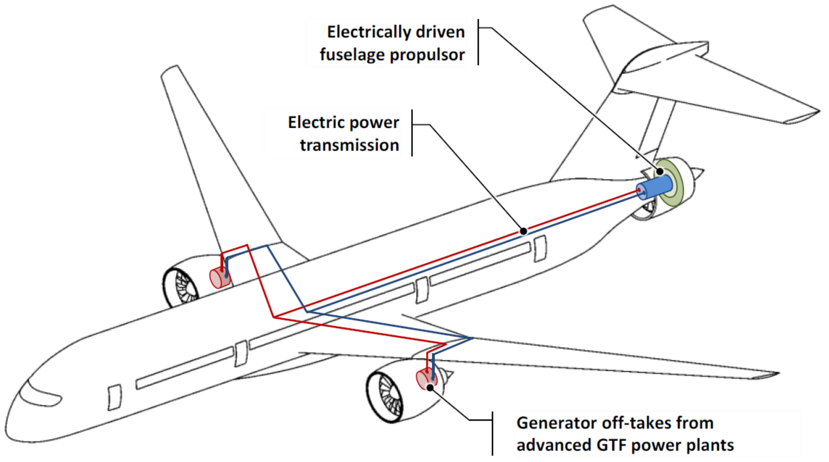
2. CENTRELINE Project Overview
3. Methodolgy
3.1. Problem Setup
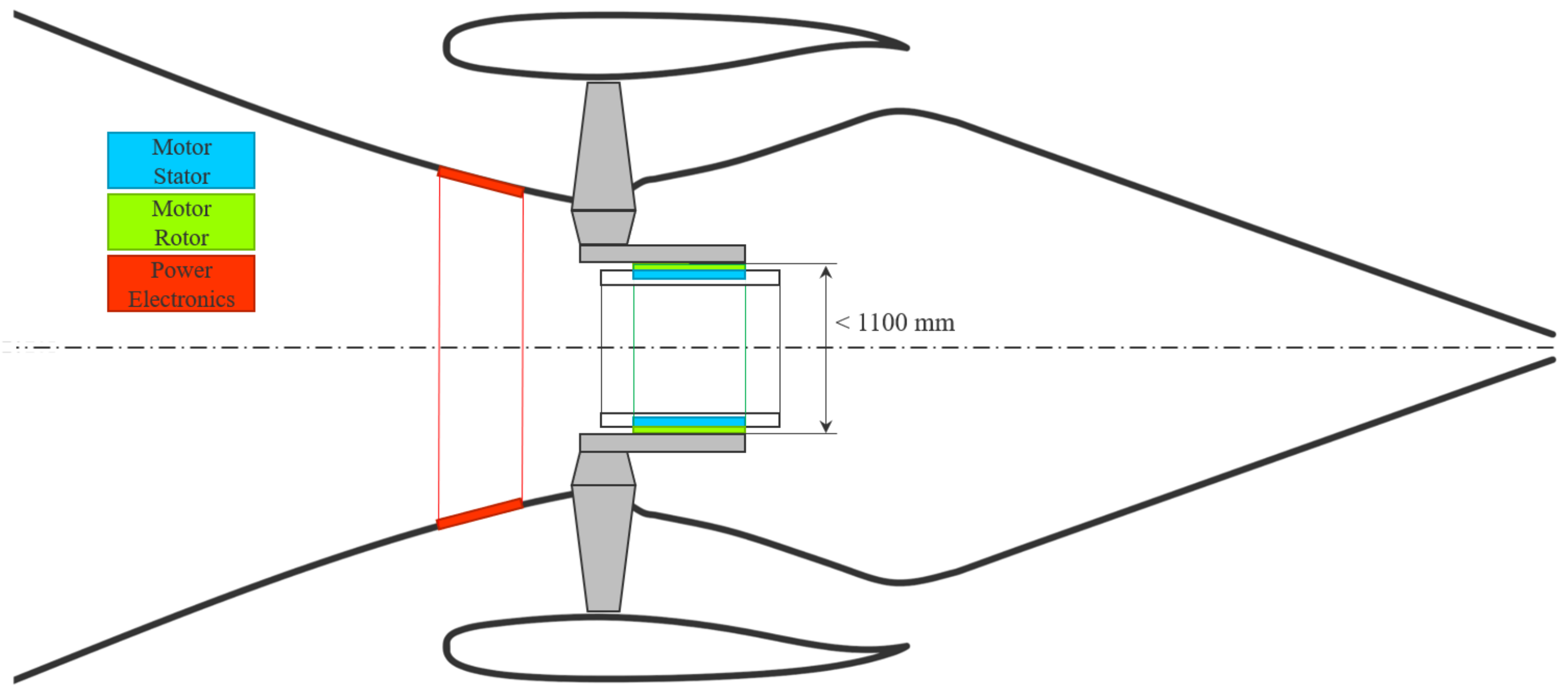
- general requirements (shaft power , rotational speed and diameter-to-length- ratio of the electric machine as well as the cable length ) which must be fulfilled by the component sizing process;
- global variation parameters which are relevant for more than one component (DC link voltage level );
- local variation parameters which only influence the design of one component (conductor current density , inverter topology , allowable chip and cable temperature );
- output/input data, i.e., results from one component sizing process which are necessary for the design process of another component (line-to-line-voltage at the motor terminal , power factor , electric frequency and the input DC current of the inverter ); and
- key performance indicators (KPI), representing relevant information, such as mass m and efficiency of the components.
3.2. Requirements, Constraints and Design Target
3.3. Detailed Description of Sizing Process of Components
3.3.1. Electric Machine
3.3.2. DC/AC Inverter
3.3.3. DC Power Transmission Cable
4. Results and Discussion of Design Space Exploration
4.1. Results for Components
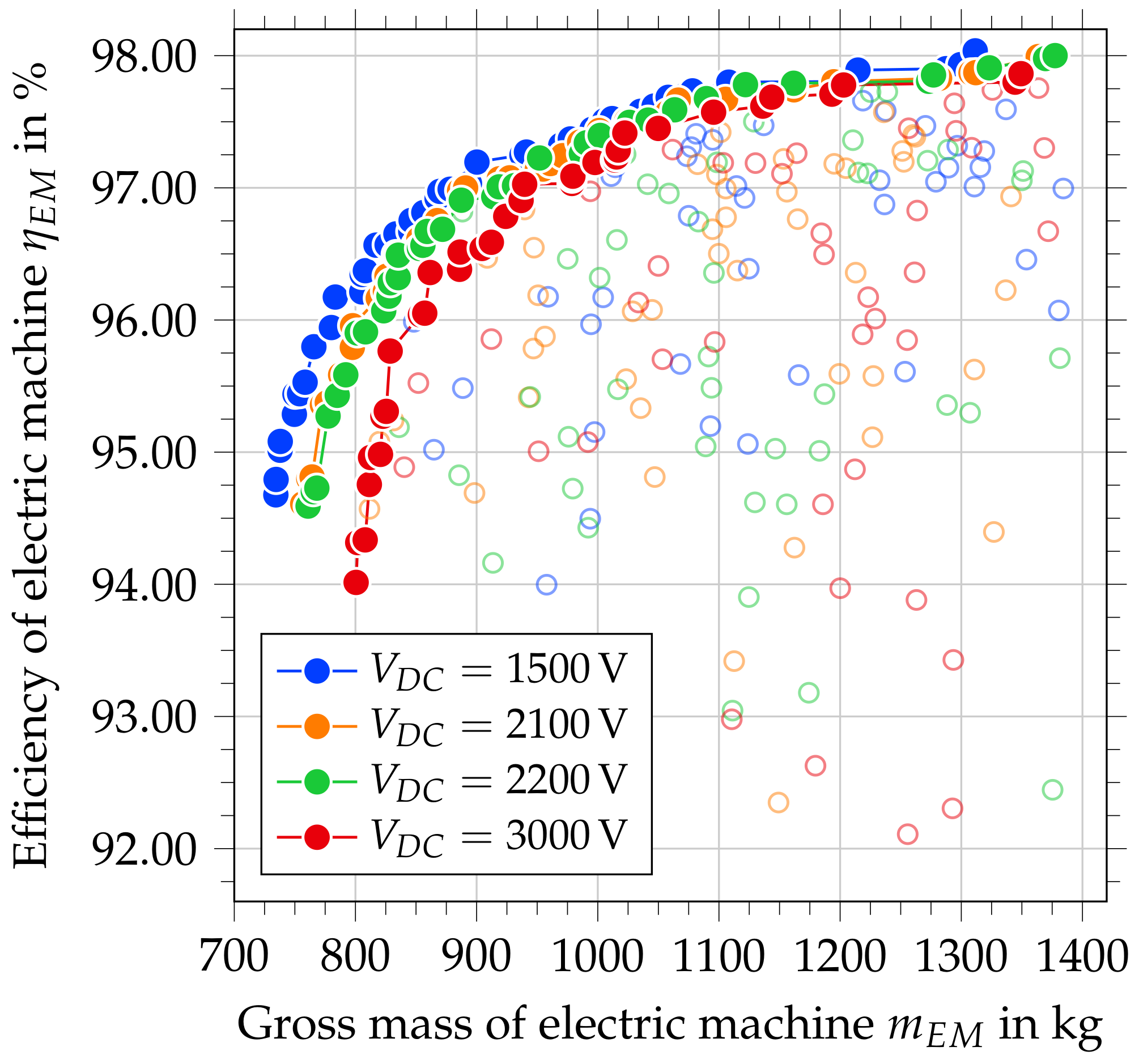
4.1.1. Electric Machine
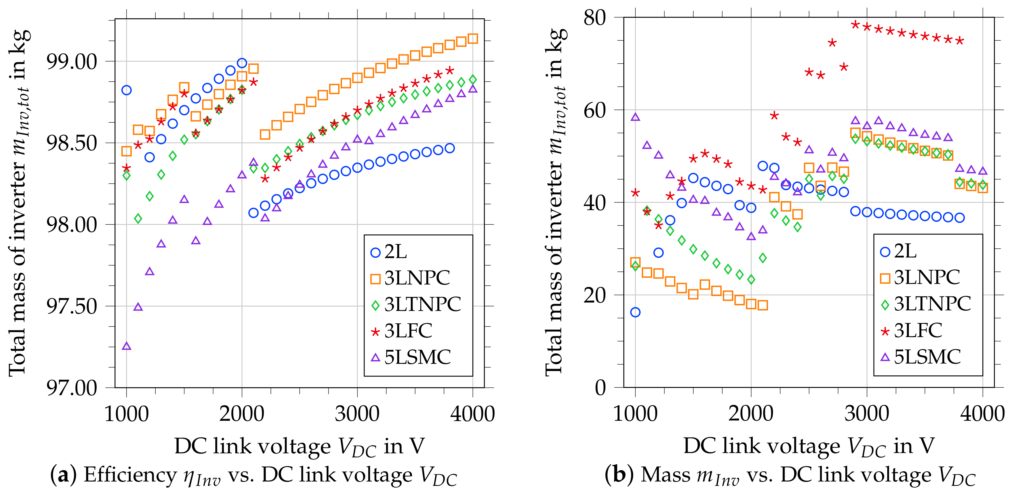
4.1.2. DC/AC Inverter
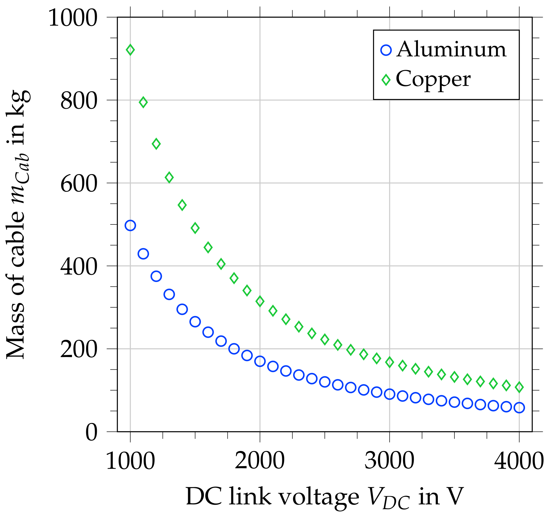
4.1.3. DC Transmission Cable
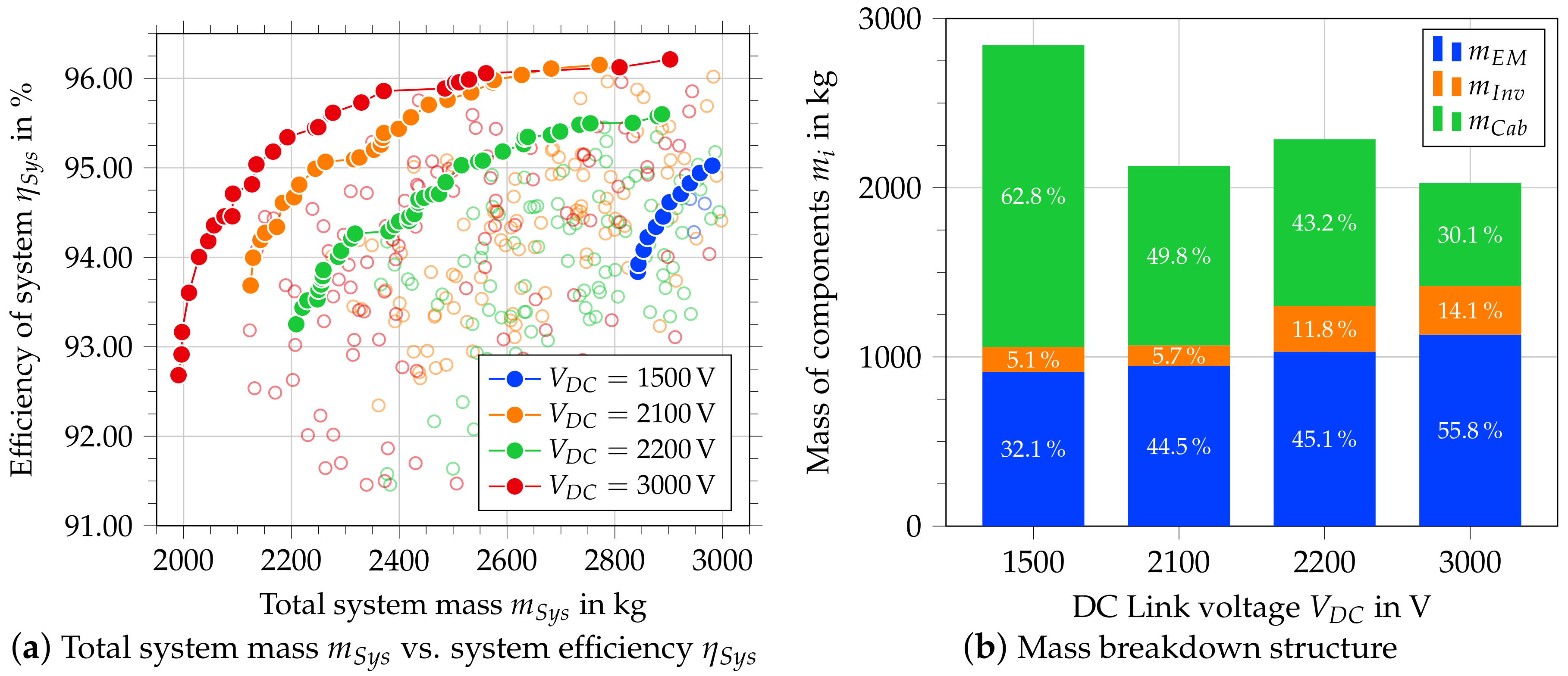
4.2. System Results
5. Conclusions
Author Contributions
Funding
Acknowledgments
Conflicts of Interest
Abbreviations
| EP | Electric Propulsion |
| DOF | Degree of Freedom |
| DSE | Design Space Exploration |
| KPI | Key Performance Indicator |
| DC | Direct Current |
| AC | Alternating Current |
| CO2 | Carbon dioxide |
| NOx | Nitrogen oxide |
| NASA | National Aeronautics and Space Exploration |
| ICAO | International Civil Aviation Organization |
| ATAG | Aviation Transport Action Group |
| MDAO | Multidisciplinary Analysis and Optimization |
| EU | European Union |
| BLI | Boundary Layer Ingestion |
| GTF | Geared Turbo Fan |
| LPT | Low Pressure Turbine |
| EM | Electric Machine |
| FF | Fuselage Fan |
| SiC | Silicon Carbide |
| PMSM | Permanent Magnet Synchronous Machine |
| THD | Total Harmonic Distortion |
| NPC | Neutral Point Clamped |
| FC | Fly Cap |
| SMC | Stacked Multi Cell |
| EMI | Electromagnetic Interference |
References
- Penner, J.E.; Lister, D.H.; Griggs, D.J.; Dokken, D.J.; McFarland, M. Aviation and the Global Atmosphere: A Special Report of the Intergovernmental Panel on Climate Change; Cambridge University Press: Cambridge, UK, 1999. [Google Scholar]
- Air Transport Action Group. Aviation: Benefit Beyond Borders; ATAG: Geneva, Switzerland, 2018. [Google Scholar]
- Follen, G.J.; Del Rosario, R.; Wahls, R.; Madavan, N. NASA’s Fundamental Aeronautics Subsonic Fixed Wing Project: Generation N+3 Technology Portfolio; SAE Technical Paper Series; SAE International: Warrendale, PA, USA, 2011. [Google Scholar]
- Guynn, M.D.; Berton, J.J.; Tong, M.J.; Haller, W.J. Advanced Single-Aisle Transport Propulsion Design Options Revisited. In Proceedings of the Aviation Technology, Integration, and Operations Conference, Los Angeles, CA, USA, 12–14 August 2013; American Institute of Aeronautics and Astronautics: Reston, VA, USA, 2013. [Google Scholar]
- International Civil Aviation Organization. Doc 10127: Independent Expert Integrated Technology Goals Assessment and Review for Engines and Aircraft; ICAO: Montréal, QC, Canada, 2019. [Google Scholar]
- International Civil Aviation Organization. Resolution A39-3: Consolidated Statement of Continuing ICAO Policies and Practices Related to Environmental Protection—Global Market-based Measure (MBM) Scheme; ICAO: Montréal, QC, Canada, 2016. [Google Scholar]
- Darecki, M.; Edelstenne, C.; Enders, T.; Fernandez, E.; Hartman, P.; Herteman, J.P.; Kerkloh, M.; King, I.; Ky, P.; Mathieu, M.; et al. Flightpath 2050: Europe’s Vision for Aviation: Report of the High Level Group; Publications Office of the European Union: Luxembourg, 2011. [Google Scholar]
- Aigner, B.; Nollmann, M.; Stumpf, E. Design of a Hybrid Electric Propulsion System within a Preliminary Aircraft Design Software Environment. In Deutscher Luft- und Raumfahrtkongress; Deutsche Gesellschaft für Luft- und Raumfahrt-Lilienthal-Oberth e.V.: Bonn, Germany, 2018; pp. 1–14. [Google Scholar]
- Brelje, B.J.; Martins, J.R.R.A. Electric, Hybrid, and Turboelectric Fixed-Wing Aircraft: A Review of Concepts, Models, and Design Approaches. Prog. Aerosp. Sci. 2019, 104, 1–19. [Google Scholar] [CrossRef]
- Voskuijl, M.; van Bogaert, J.; Rao, A.G. Analysis and Design of Hybrid Electric Regional Turboprop Aircraft. CEAS Aeronaut. J. 2018, 9, 15–25. [Google Scholar] [CrossRef]
- Gemin, P.; Kupiszewski, T.; Radun, A.; Pan, Y.; Lai, R.; Zhang, D.; Wang, R.; Wu, X.; Jiang, Y.; Galioto, S.; et al. Architecture, Voltage, and Components for a Turboelectric Distributed Propulsion Electric Grid (AVC-TeDP); NASA Glenn Research Center: Cleveland, OH, USA, 2015.
- Gesell, H.; Wolters, F.; Plohr, M. System of Turbo Electric and Hybrid Electric Propulsion Systems on a Regional Aircraft. In Proceedings of the 31st Congress of the International Council of the Aeronautical Sciences (ICAS), Horizonte, Brazil, 9–14 September 2018; pp. 9–14. [Google Scholar]
- Pornet, C. Electric Drives for Propulsion System of Transport Aircraft. In New Applications of Electric Drives; Chomat, M., Ed.; InTech: London, UK, 2015. [Google Scholar]
- Isikveren, A.T.; Seitz, A.; Vratny, P.C.; Pornet, C.; Plötner, K.O.; Hornung, M. Conceptual Studies of Universally-Electric Systems Architectures Suitable for Transport Aircraft. In Deutscher Luft-und Raumfahrt Kongress; Deutsche Gesellschaft für Luft- und Raumfahrt: Bonn, Germany, 2012. [Google Scholar]
- Andrea, J.; Buffo, M.; Guillard, E.; Landfried, R.; Boukadoum, R.; Teste, P. Arcing Fault in Aircraft Distribution Network. In Proceedings of the 2017 IEEE Holm Conference on Electrical Contacts, Denver, CO, USA, 10–13 September 2017; IEEE: Piscataway, NJ, USA, 2017; pp. 317–324. [Google Scholar]
- Nya, B.H.; Brombach, J.; Schulz, D. Benefits of Higher Voltage Levels in Aircraft Electrical Power Systems. In Proceedings of the 2012 Electrical Systems for Aircraft, Railway and Ship Propulsion Conference, Bologna, Italy, 16–18 October 2012; pp. 1–5. [Google Scholar]
- Jansen, R.; Bowman, C.; Jankovsky, A. Sizing Power Components of an Electrically Driven Tail Cone Thruster and a Range Extender. In Proceedings of the 16th AIAA Aviation Technology, Integration, and Operations Conference, Washington, DC, USA, 13–17 June 2016; p. 3766. [Google Scholar]
- Seitz, A. H2020 CENTRELINE—Project Preview. In Proceedings of the 7th EASN International Conference, Warsaw, Poland, 26–29 September 2017. [Google Scholar]
- Pornet, C.; Gologan, C.; Vratny, P.C.; Seitz, A.; Schmitz, O.; Isikveren, A.T.; Hornung, M. Methodology for Sizing and Performance Assessment of Hybrid Energy Aircraft. J. Aircr. 2015, 52, 341–352. [Google Scholar] [CrossRef]
- Riboldi, C.E.D.; Gualdoni, F.; Trainelli, L. Preliminary Weight Sizing of Light Pure-Electric and Hybrid- Electric Aircraft. Transp. Res. Procedia 2018, 29, 376–389. [Google Scholar] [CrossRef]
- Stückl, S. Methods for the Design and Evaluation of Future Aircraft Concepts Utilizing Electric Propulsion Systems. Ph.D. Thesis, TU München, Munich, Germany, 2016. [Google Scholar]
- Vratny, P.C. Conceptual Design Methods of Electric Power Architectures for Hybrid Energy Aircraft. Ph.D. Thesis, TU München, Munich, Germany, 2019. [Google Scholar]
- Vratny, P.C.; Hornung, M. Sizing Considerations of an Electric Ducted Fan for Hybrid Energy Aircraft. Transp. Res. Procedia 2018, 29, 410–426. [Google Scholar] [CrossRef]
- Isikveren, A.T.; Seitz, A.; Bijewitz, J.; Hornung, M.; Mirzoyan, A.; Isyanov, A.; Godard, J.L.; Stückl, S.; van Toor, J. Recent Advances in Airframe-Propulsion Concepts with Distributed Propulsion. In Proceedings of the 29th Congress of the International Council of the Aeronautical Sciences (ICAS), St. Petersburg, Russia, 7–12 September 2014. [Google Scholar]
- Meller, F.; Kocvara, F. Specification of Propulsive Fuselage Aircraft Layout and Design Features: Grant Agreement No. 723242, CENTRELINE Project Deliverable D1.02; Publications Office of the European Union: Luxembourg, 2018. [Google Scholar]
- Seitz, A.; Peter, F.; Bijewitz, J.; Habermann, A.; Goraj, Z.; Kowalski, M.; Castillo, A.; Meller, F.; Merkler, R.; Samuelsson, S.; et al. Concept Validation Study for Fuselage Wake-Filling Propulsion Integration. In Proceedings of the 31st Congress of the International Council of the Aeronautical Sciences (ICAS), Belo Horizonte, Brazil, 9–14 September 2018. [Google Scholar]
- Wortmann, G. Electric Machinery Preliminary Design Report: Grant Agreement No. 723242, CENTRELINE Project Deliverable D4.04; Publications Office of the European Union: Luxembourg, 2018. [Google Scholar]
- Fang, L.C.; Qin, S.Y. Concurrent Optimization for Parameters of Powertrain and Control System of Hybrid Electric Vehicle Based on Multi-Objective Genetic Algorithms. In Proceedings of the 2006 SICE-ICASE International Joint Conference, Busan, Korea, 18–21 October 2006; pp. 2424–2429. [Google Scholar]
- Cao, W.; Mecrow, B.C.; Atkinson, G.J.; Bennett, J.W.; Atkinson, D.J. Overview of Electric Motor Technologies Used for More Electric Aircraft (MEA). IEEE Trans. Ind. Electron. 2012, 59, 3523–3531. [Google Scholar]
- Hsieh, M.; Hsu, Y. A Generalized Magnetic Circuit Modeling Approach for Design of Surface Permanent- Magnet Machines. IEEE Trans. Ind. Electron. 2012, 59, 779–792. [Google Scholar] [CrossRef]
- Siemens PLM Software Inc. Simcenter SPEED: PC-BDC 13.06 User’s Manual; Siemens PLM Software Inc.: Plano, TX, USA, 2018. [Google Scholar]
- Boresi, A.P.; Schmidt, R.J. Advanced Mechanics of Materials, 6th ed.; Wiley: New York, NY, USA, 2003. [Google Scholar]
- Eslami, M.R. Theory of Elasticity and Thermal Stresses: Explanations, Problems and Solutions. In Solid Mechanics and Its Applications; Springer: Dordrecht, The Netherlands, 2013; Volume 197. [Google Scholar]
- IEC 60664-1:2007. Insulation Coordination for Equipment within Low-Voltage Systems; VDE-Verlag: Berlin, Germany, 2007. [Google Scholar]
- Golovanov, D.; Papini, L.; Gerada, D.; Xu, Z.; Gerada, C. Multidomain optimization of High-Power-Density PM Electrical Machines for System Architecture Selection. IEEE Trans. Ind. Electron. 2018, 65, 5302–5312. [Google Scholar] [CrossRef]
- Krug, D. Vergleichende Untersuchungen von Mehrpunkt-Schaltungstopologien mit zentralem Gleich- Spannungszwischenkreis für Mittelspannungsanwendungen. (German) [Comparison of Medium-Voltage Multilevel Converters with Central DC Link, Chap. 3]. Ph.D. Thesis, TU Dresden, Dresden, Germany, 2016. [Google Scholar]
- Krug, D.; Bernet, S.; Fazel, S.S.; Jalili, K.; Malinowski, M. Comparison of 2.3-kV Medium-Voltage Multilevel Converters for Industrial Medium-Voltage Drives. IEEE Trans. Ind. Electron. 2007, 54, 2979–2992. [Google Scholar] [CrossRef]
- Brückner, T. The Active NPC Converter for Medium Voltage Drives. Ph.D. Thesis, RWTH Aachen, Aachen, Germany, 2006. [Google Scholar]
- Wintrich, A.; Nicolai, U.; Tursky, W.; Reimann, T. Application Manual Power Semiconductors; ISLE Verlag: Ilmenau, Germany, 2011. [Google Scholar]
- Ilgevicius, A. Analytical and Numerical Analysis and Simulaiton of Heat Transfer in Electrical Conductors and Fuses. Ph.D. Thesis, Universität der Bundeswehr München, Neubiberg, Germany, 2014. [Google Scholar]
- Van der Geest, M.; Polinder, H.; Ferreira, J.A.; Christmann, M. Power Density Limits and Design Trends of High-Speed Permanent Magnet Synchronous Machines. IEEE Trans. Transp. Electrif. 2015, 1, 266–276. [Google Scholar] [CrossRef]
- Kolar, J.W.; Drofenik, U.; Biela, J.; Heldwein, M.L.; Ertl, H.; Friedli, T.; Round, S.D. PWM Converter Power Density Barriers. In Proceedings of the Power Conversion Conference, Nagoya, Japan, 2–5 April 2007; pp. 9–29. [Google Scholar]
- Coroplast GmbH & Co. KG. Wires and Cables for Automotive Applications; Coroplast GmbH & Co. KG: Wuppertal, Germany, 2016. [Google Scholar]


| Component | Parameter | Range/Value | Unit | Description |
|---|---|---|---|---|
| Electric machine | 8000 | mechanical shaft power | ||
| 2100 | shaft rotational speed | |||
| 6–8 | specific thrust | |||
| 1–2 | - | diameter-length-ratio rotor | ||
| p | 12–50 | - | number of polepairs | |
| Q | 36–141 | - | number of stator slots | |
| 9–12 | thickness of magnets | |||
| 17.5 | conductor current density | |||
| DC/AC Inverter | 1000 | electric output power | ||
| 8 | - | number of parallel inverters | ||
| 2L, 3LNPC, | - | topology | ||
| 3LTNPC, | ||||
| 3LFC, 5LSMC | ||||
| SiC | - | semiconductor technology | ||
| 75 | cooling inlet temperature | |||
| 150 | allowable chip temperature | |||
| 105 | area specific thermal resistance case to cooling fluid | |||
| DC transmission cable | 1000 | DC power per transmission line | ||
| 86.0 | total length | |||
| 1500–3000 | DC link voltage | |||
| 120 | allow. conductor temperature | |||
| 55 | ambient temperature |
© 2019 by the authors. Licensee MDPI, Basel, Switzerland. This article is an open access article distributed under the terms and conditions of the Creative Commons Attribution (CC BY) license (http://creativecommons.org/licenses/by/4.0/).
Share and Cite
Biser, S.; Wortmann, G.; Ruppert, S.; Filipenko, M.; Noe, M.; Boll, M. Predesign Considerations for the DC Link Voltage Level of the CENTRELINE Fuselage Fan Drive Unit. Aerospace 2019, 6, 126. https://doi.org/10.3390/aerospace6120126
Biser S, Wortmann G, Ruppert S, Filipenko M, Noe M, Boll M. Predesign Considerations for the DC Link Voltage Level of the CENTRELINE Fuselage Fan Drive Unit. Aerospace. 2019; 6(12):126. https://doi.org/10.3390/aerospace6120126
Chicago/Turabian StyleBiser, Stefan, Guido Wortmann, Swen Ruppert, Mykhaylo Filipenko, Mathias Noe, and Martin Boll. 2019. "Predesign Considerations for the DC Link Voltage Level of the CENTRELINE Fuselage Fan Drive Unit" Aerospace 6, no. 12: 126. https://doi.org/10.3390/aerospace6120126