Article

Electric Aerospace Actuator Manufactured by Laser Powder Bed Fusion

by
Borja Lizarribar
1,2,*,
Borja Prieto
1,2,
Miren Aristizabal
1,2,
Jose Manuel Martín
1,2,
Miguel Martínez-Iturralde
1,2,
Ekain San José
3,
Ione Golvano
3 and
Sergio Montes
3
1
CEIT-Basque Research and Technology Alliance (BRTA), Manuel Lardizabal 15, 20018 San Sebastián, Spain
2
Universidad de Navarra, Tecnun School of Engineering, Manuel Lardizabal 13, 20018 San Sebastián, Spain
3
Egile Mechanics S.L., Polígono Industrial Kurutz-Gain, 12, 20850 Mendaro, Spain
*
Author to whom correspondence should be addressed.
Aerospace 2023, 10(9), 813; https://doi.org/10.3390/aerospace10090813
Submission received: 20 July 2023 / Revised: 11 September 2023 / Accepted: 14 September 2023 / Published: 17 September 2023
(This article belongs to the Special Issue Metal Additive Manufacturing for Aerospace Applications)

Abstract

:
Recent advances in manufacturing methods have accelerated the exploration of new materials and advantageous shapes that could not be produced by traditional methods. In this context, additive manufacturing is gaining strength among manufacturing methods for its versatility and freedom in the geometries that can be produced. Taking advantage of these possibilities, this research presents a case study involving an electric aerospace actuator manufactured using additive manufacturing. The main objectives of this research work are to assess the feasibility of additively manufacturing electric actuators and to evaluate potential gains in terms of weight, volume, power consumption and cost over conventional manufacturing technologies. To do so and in order to optimise the actuator design, a thorough material study is conducted in which three different magnetic materials are gas-atomised (silicon iron, permendur and supermalloy) and test samples of the most promising materials (silicon iron and permendur) are processed by laser powder bed fusion. The final actuator design is additively manufactured in permendur for the stator and rotor iron parts and in 316L stainless steel for the housing. The electric actuator prototype is tested, showing compliance with design requirements in terms of torque production, power consumption and heating. Finally, a design intended to be manufactured via traditional methods (i.e., punching and stacking for the stator laminations and machining for the housing) is presented and compared to the additively manufactured design. The comparison shows that additive manufacturing is a viable alternative to traditional manufacturing for the application presented, as it highly reduces the weight of the actuator and facilitates the assembly, while the cost difference between the two designs is minimal.

1. Introduction

The trends set by more electric aircraft (MEA) aim to reduce the number of pneumatic, mechanical and hydraulic systems and replace them with electrically powered actuators [1]. This goal of electrifying the aerospace sector is also supported by the Clean Sky 2 programme, which aims to be the main contributor to the Commission’s Flightpath 2050 goals, set by ACARE. These objectives are:
  • A 75% reduction in C O 2 emissions.
  • A 90% reduction in N O X emissions.
  • The perceived noise of flying aircraft reduced by 65%.
  • Air vehicles designed and manufactured to be recyclable.
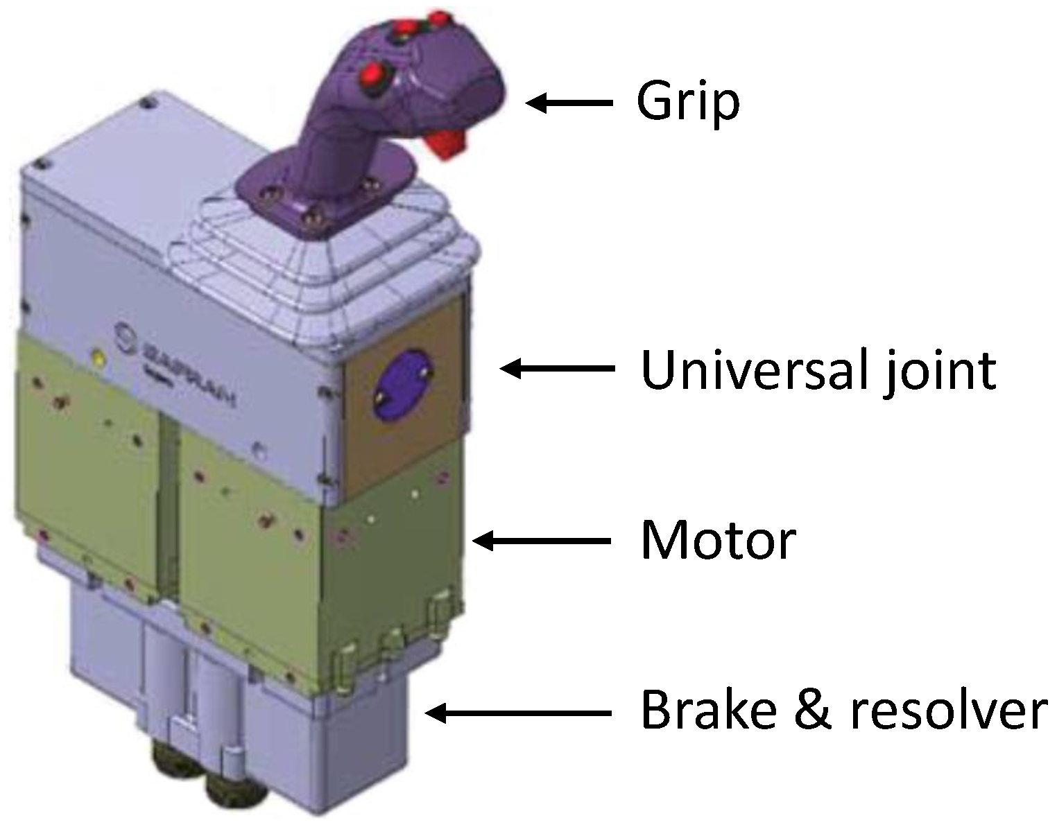
For this matter, reducing the weight of aircraft components is a key factor, as aircraft weight is one of the main contributors to fuel consumption and, hence, emissions. In this scenario, additive manufacturing (AM) is gaining strength due to the advantages it reports in terms of geometric flexibility and material savings. More specifically, AM in the aerospace sector has become a viable solution for the production of various parts, ranging from small cabin brackets [2] and hinge brackets [3], to larger and more critical components such as turbopump stators [4] and a rocket nozzles [5]. Moreover, AM has been proven effective for the construction of various aerospace components [6] and it is regarded to bring benefits over traditional manufacturing in terms of weight, lead time reduction and cost for a number of components [7].
In addition to the flexibility of the geometries that can be produced, AM also allows a wide variety of materials to be processed. A comprehensive review of the metallic materials available for AM is provided in [8], in which various materials are surveyed, such as Ni-based, Fe-based, Cu-based, Al-based, Ti-based and so on. Examples of aerospace components produced by AM can be found in [2,3,9] (Ti-based alloys), in [10] (Cu-based alloys) and in [11] (Fe-based alloys).
Not only have mechanical parts for aeronautics been produced already via AM, but also magnetic [12,13] and thermal management [14,15,16,17,18] components have been manufactured as well. It is worth highlighting the case presented in [12], in which the rotor and the shaft of a direct current (DC) motor for an UAV aircraft are manufactured via selective laser sintering (SLS) in A6 steel. Copper and aluminum alloys have been additively manufactured as well, showing promising results for electrical machine design in terms of heat extraction and loss reduction at high-frequency operation [19,20,21]. Further examples of electrical machine components made using AM and unusual magnetic materials can be found in [22,23] (Fe-Al alloy), [24] (17-4PH stainless steel) and [25] (pure Fe). In this regard, despite the wide variety of materials that can be produced by AM, the use of additively produced soft magnetic materials is not widespread. Nevertheless, various attempts at additively processing said materials can be found in [26,27,28,29,30] (FeSi alloys), [31,32] (FeCo alloys) and [33] (FeNi), for instance.
In the context of aircraft electrification, emission and weight reduction and additive manufacturing, the present work presents a case study involving the AM of an electric actuator for an active inceptor system. The Smart Active Inceptor system, developed by Safran Electronics & Defense, consists of a joystick-type control interface that provides tactile feedback to pilots for a civil tiltrotor aircraft, following a fly-by-wire concept. The aim of the present work has been to analyse the feasibility of manufacturing electric actuators using a laser powder bed fusion (LPBF) technique (also known as selective laser melting, SLM) and to evaluate the gains in terms of weight, volume, power consumption and cost over conventional manufacturing technologies. For this purpose, gas-atomised soft magnetic metallic compositions have been analysed, powder bed fusion (PBF) process parameters have been optimised and an electric actuator prototype has been manufactured.
This article is structured as follows: first, the case study is presented and the requirements for the designed actuator are briefly summarised in Section 2. The materials considered for the application and their assessment are then discussed in Section 3. Two equivalent actuator designs, one intended to be manufactured additively and the other one in traditional terms, are described in Section 4 and are compared in terms of weight, volume and cost. A brief note on the fabrication and testing of an AM actuator prototype is given in Section 5, and finally, the conclusions of the present work and some considerations regarding future work are stated in Section 6.

2. Case Study

As stated in Section 1, the case study presented in this research work involves the design and manufacturing of an electric actuator (or motor) for an active inceptor system, shown in Figure 1. As illustrated, the main elements of the system involve a handle, a kinematic joint that connects the two-axis movement of the grip to two motors/actuators and a set of safety brakes and resolvers for controlling those. The torque produced by the electric motors is what allows the user to experience controlled force-feedback when holding the sidestick. The performance requirements specified for each of the motor units are summarised in Table 1.
Regarding the AM approach for the actuator, the nearly zero speed of the inceptor application, which must provide force to the grip under no or little movement, makes it very suitable to consider the AM of the soft magnetic actuator parts. In conventional electric motors, which operate at non-zero frequencies (typically 50/60 Hz in industrial applications and 400 Hz in aircraft electrical power distribution), significant energy losses occur in the soft magnetic material parts due to induced eddy currents when subjected to variable magnetic fields. For this reason, it is common for stators and rotors in electrical machines manufactured by non-additive technologies to be made by die-cutting and stacking insulated thin silicon steel sheets (the addition of silicon increases the electrical resistivity of the material and reduces energy losses). For soft magnetic materials fabricated by AM, several techniques have been proposed to emulate the effect of lamination for reducing eddy current losses in the solid material [26,35,36].
In addition, the additive manufacturing of structural parts has also been considered in this project. The additive manufacturing of the hard magnetic parts has been discarded because, for the time being, except for very specific AM processes such as cold spray [37,38,39], the magnetic performance (coercivity, remanence) of the resulting magnets is far from that of conventional sintered rare earth magnets [40,41,42,43]. Additive manufacturing of copper coils has also not been considered due to the small size of the actuator and the high number of turns that the near-zero speed requires to achieve the desired voltage.
The result of the design exercise is shown in Section 4, after detailing the atomisation and optimisation of the additive manufacturing process.

3. Material Assessment and Testing

Additive manufacturing of stainless steels is well established in the literature [8] and metallic powder for the AM of different steel compositions is already available in the market. On the other hand, the commercial availability of magnetic alloys is much lower, so one of the main lines of research opened up by this project has been the AM of soft magnetic materials. Key highlights regarding gas atomisation of magnetic powders, LPBF processing of said materials and heat treatment (HT) optimisation for permendur test samples are provided within this section.

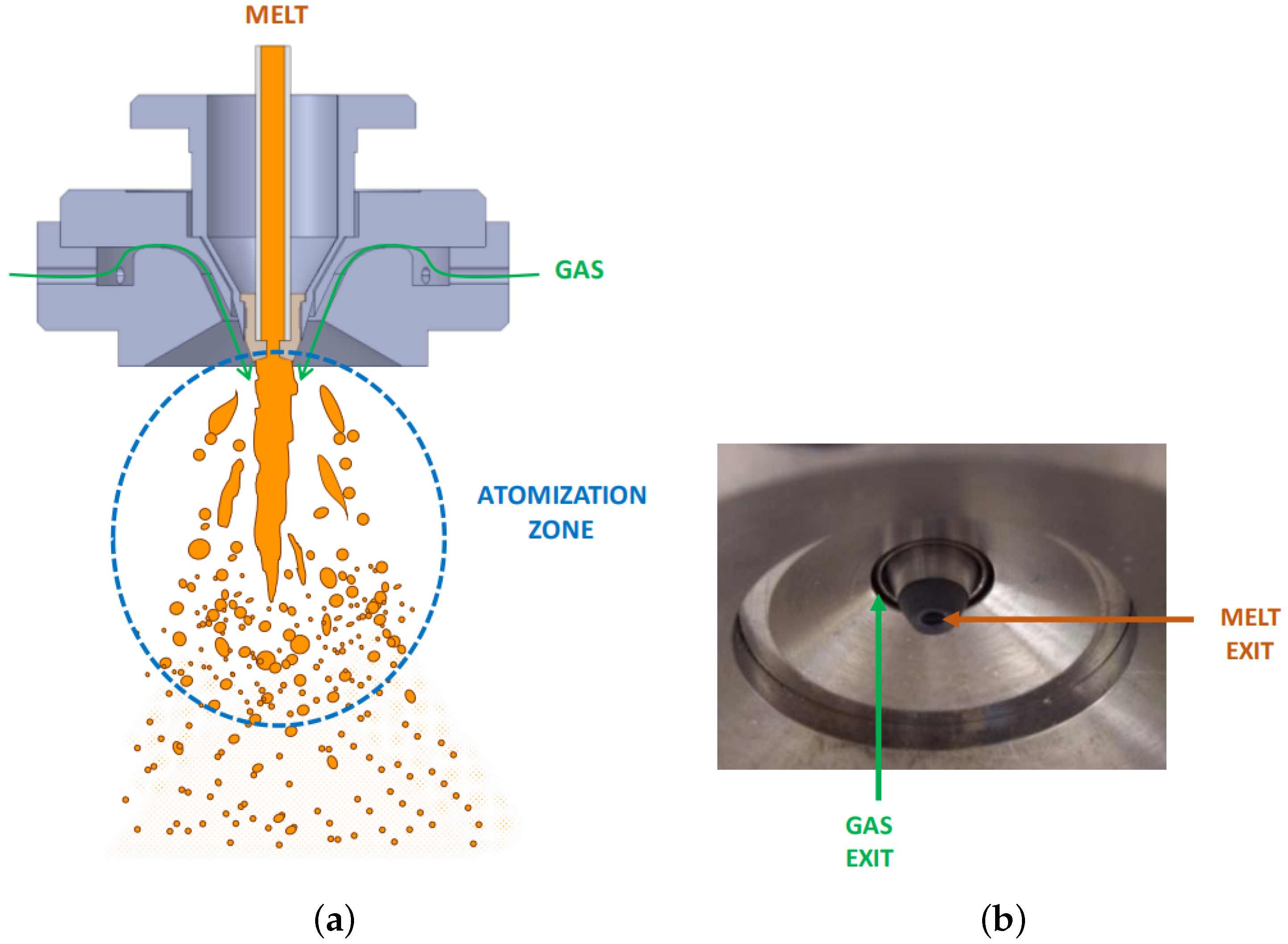
3.1. Gas Atomisation of Soft Magnetic Materials

Gas atomisation is one of the main methods to manufacture the metallic powders used by the powder metallurgy industry [44]. It is highly versatile, as it can be used with many different alloys, the control of the particle size distribution is good and the output is high. Moreover, the powder has a low oxygen content and a spherical particle shape. These features make gas atomisation the reference technology for producing powders for AM. As illustrated by Figure 2, the principle of this powder production method is to transfer kinetic energy from a high-speed gas jet to a liquid metal stream that becomes unstable. The expansion of the gas around the molten stream causes a dramatic depressurisation and the disintegration of the liquid into small droplets which solidify as powder particles. In this work, experimental atomisations have been conducted in an atomisation unit (PSI model HERMIGA 75/3VI) using a close-coupled, convergent–divergent atomiser in which the gas nozzle has the shape of an annular slot (see Figure 2). The raw materials are charged into a high purity alumina crucible and melted by induction under argon. The atomisation chamber is also evacuated and purged with argon to minimise oxidation. The plant is capable of producing about 3 kg of powder per batch. The melt is superheated to 200 °C above its liquidus temperature, injected into the atomisation chamber and atomised using an argon stream at a stagnation pressure of 5.0–5.5 MPa.
Regarding the selection of soft magnetic materials for the magnetic circuit of electric actuators, the most relevant properties are high permeability, high saturation flux density and low coercivity. Three different soft magnetic material compositions that trade these properties have been considered thus within this project:
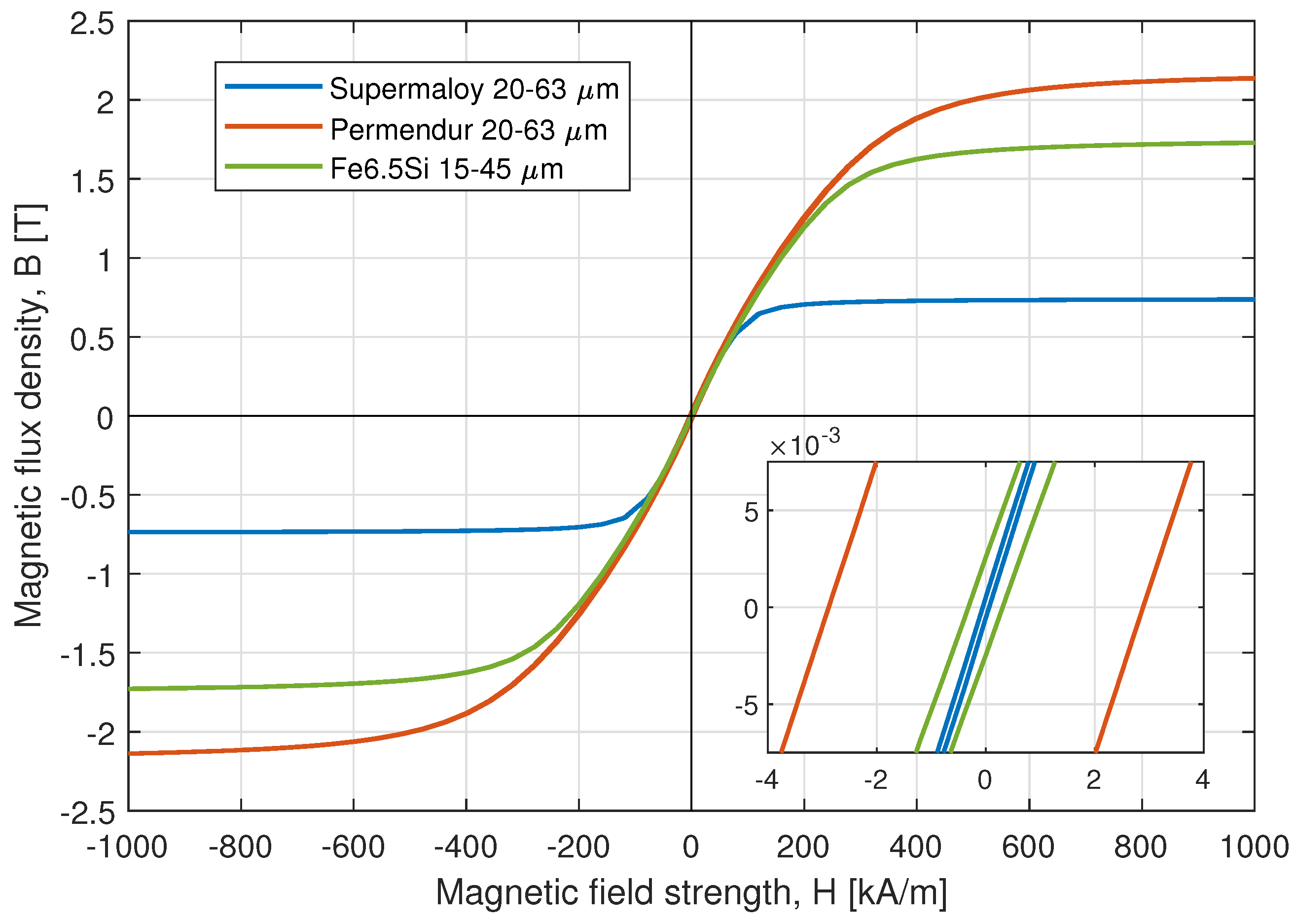
  • Supermalloy: An 80% nickel–iron–molybdenum alloy with extremely high initial and maximum permeability and minimum hysteresis loss. It is used primarily for transformer cores, tape-wound toroids, electromagnetic shielding and laminations operating at very low magnetic field strengths. Supermalloy has been manufactured via LPBF/SLM, for instance, in [46].
  • Fe6.5Si: A soft magnetic alloy with high magnetic permeability, low coercive force and low iron loss. The main advantage of this material is that it has the lowest price among the options analysed. Additionally, this material has also presented promising results in terms of magnetic properties [47,48].
  • Permendur (49Fe49Co2V): A cobalt–iron soft-magnetic alloy that stands out for its high magnetic saturation. Due to its high price, it is used in high-end applications, such as aerospace actuators, tape toroids and medium-frequency transformer laminations. Examples of LPBF processing of permendur can be found in [49].
Within this project, Fe6.5Si powder was purchased from Sandvik Osprey Ltd.(Sandviken, Sweden), in the 15–45 µm fraction, and supermalloy and permendur compositions were gas-atomised and then sieved to the appropriate fraction at CEIT’s premises. The magnetic properties of the powders at room temperature (around 22 °C) were evaluated from the hysteresis loop obtained in a Quantum Design PPMS-9T system with vibrating sample magnetometer (VSM). The magnetic characterisation of the powder is summarised in Figure 3 and Table 2. It can be observed that, as expected, supermalloy powder shows much lower magnetisation and coercivity figures. On the other hand, Fe6.5Si and permendur powder exhibit higher saturation flux density values, at the expense of a higher coercivity, which implies higher hysteresis losses.
Four different physical properties were measured for the magnetic powders: the flow rate, the apparent density, the tap density and pycnometer density. The flow rate quantifies the ability of each powder to flow, whereas the density of the powder allows one to estimate the internal porosity of the powders. The Hall flowmeter funnel method was used to measure the flow rate and the apparent density of the powders, following Metal Powder Industries Federation (MPIF) standard #4 and #28, and an AccuPyc1330 pycnometer was used for the pycnometer density. MPIF standard #46 was followed to measure the tap density of the powders. Additionally, the chemical composition, morphology and microstructure of the powders were analysed via inductive coupled plasma mass spectrometry (ICP-OES, equipment: Varian 725-ES) and scanning electron microscopy (SEM). Finally, interstitial elements within the powder were measured by means of LECO analyses. A LECO TC-400 series oxygen/nitrogen fusion analyser was used to determine the oxygen and nitrogen content of and a LECO CS-200 Series carbon/sulphur combustion analyser was employed for the carbon and sulphur contents. The main physical properties are collected in Table 3. The Hausner ratio, obtained as the ratio of the tap to apparent density, gives information about the flowability of the powder material; with a Hausner ratio greater than 1.25 being an indication of poor flowability for AM processes. As observed in the table, the three metallic compositions exhibit a suitable Hausner ratio for PBF applications.
Due to the requirements of the application (i.e., very high torque density and near-zero speed), it was decided to discard the supermalloy for further analysis, as its low saturation flux density impacts negatively on the weight reduction capability for the actuator and the magnetic losses are of little importance due to the very low frequency of operation.

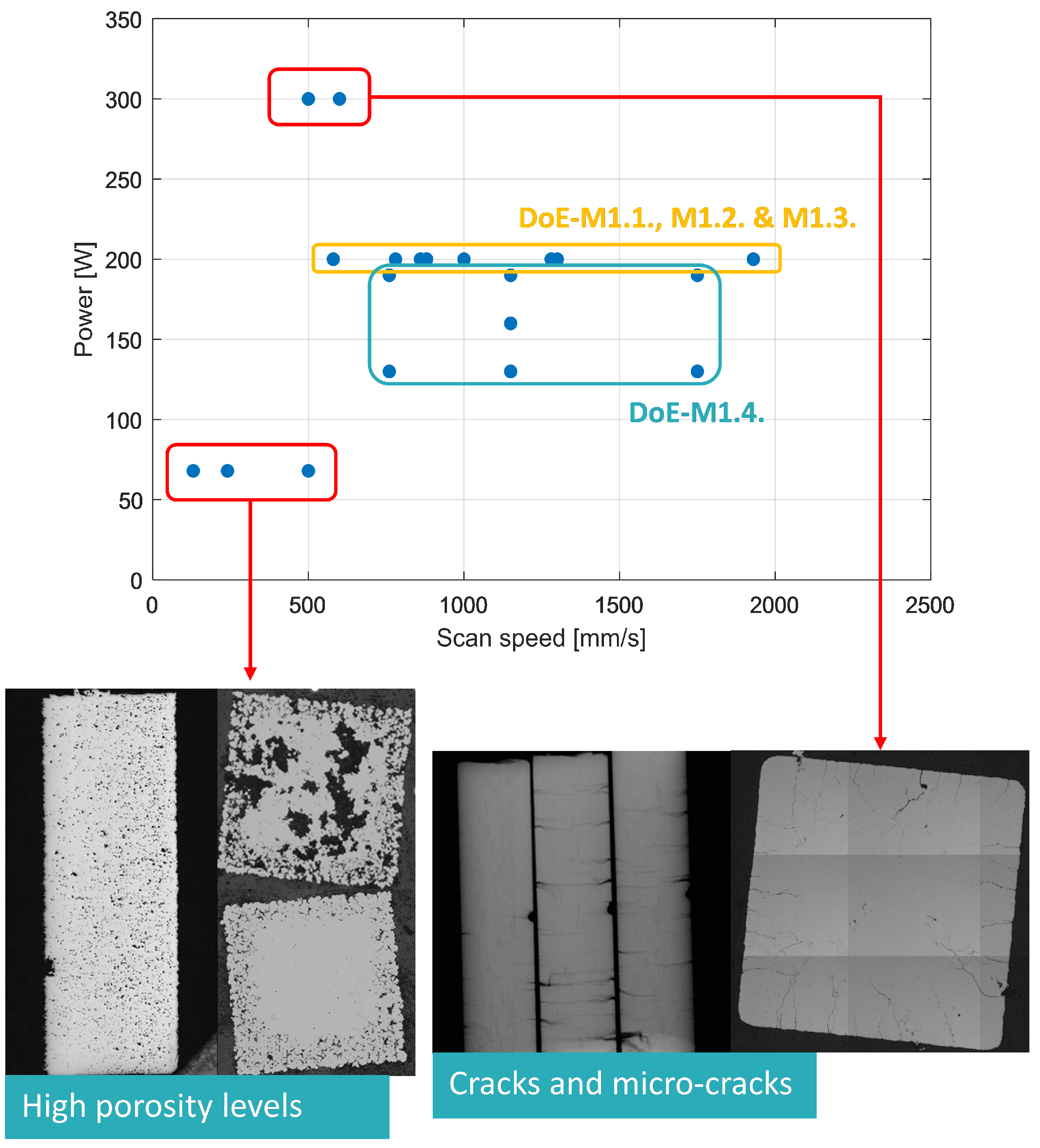
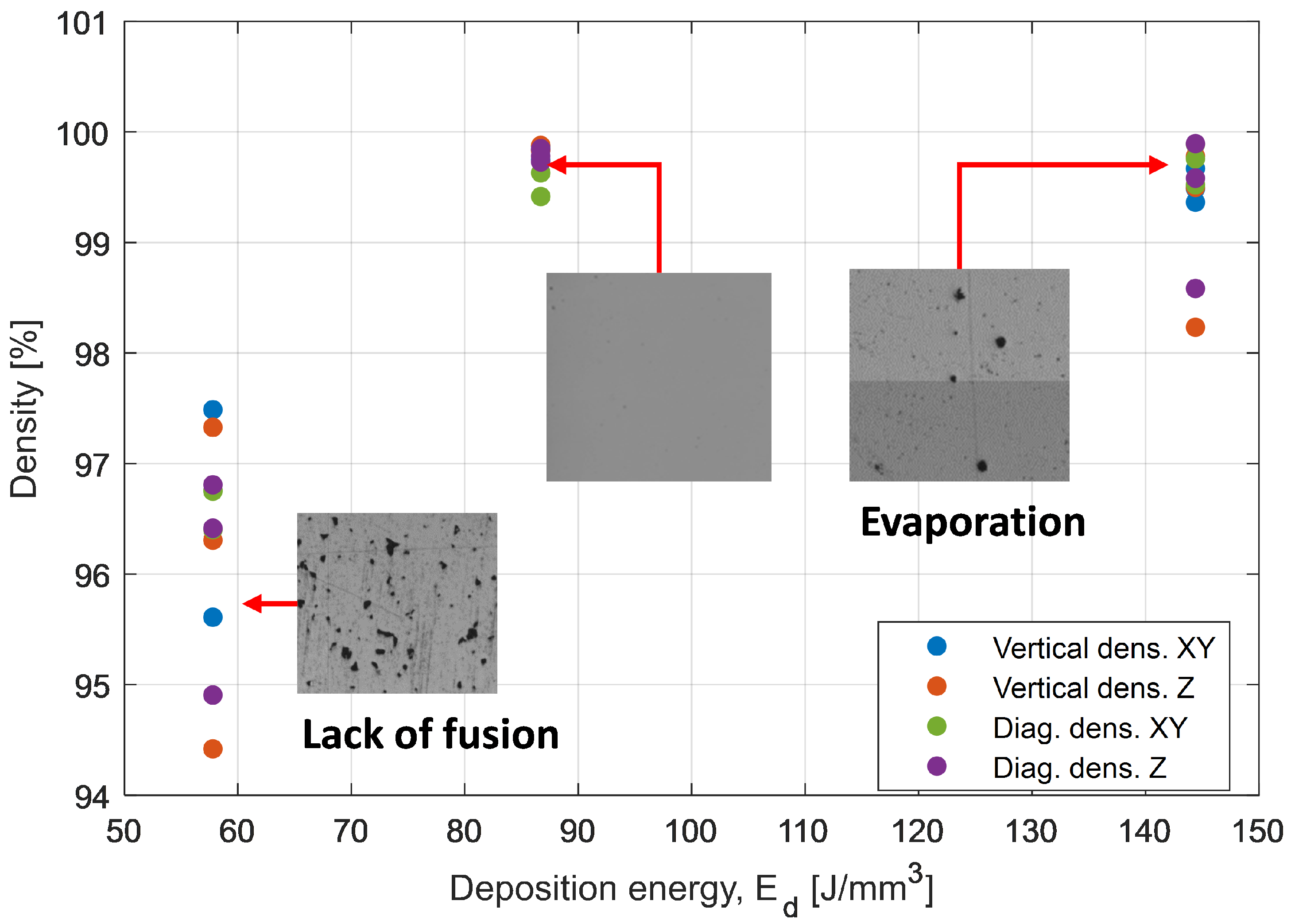
3.2. Laser Powder Bed Fusion of Test Samples

After analysing the gas-atomised powder, testable parts were produced in a Renishaw AM 400 machine. The size of the manufactured test samples is 5 × 10 × 48 mm, adequate both for mechanical and magnetic characterisation tests. The test samples were mechanically characterised in a universal testing machine (Instron 5892), whereas the DC magnetic hysteresis loop for the samples was measured using an adjustable pole electromagnet (GMW magnet systems 3470). For both AM-processed materials, Fe6.5Si and permendur, an optimisation of the LPBF process parameters, namely hatch distance, laser power and scan speed, was carried out to obtain the best combination in terms of cracks, porosity and productivity. The search for optimal process parameters was conducted through several iterations under a design of experiments (DoE) approach.
  • Fe6.5Si test samples
In the LPBF parameter development process for the Fe6.5Si alloy, four iterations were performed. Test samples manufactured during the first three iterations presented either burnt surfaces, cracks or micro-cracks. In the fourth and final iteration, test samples with no cracks and an acceptable porosity level of 1.3% were attained. The parameter optimisation process for the Fe6.5Si is illustrated in Figure 4.
Magnetic measurements on the test samples manufactured in the last DoE iteration showed average magnetisation saturation and coercivity values of 171 emu/g and 2.2 Oe, respectively; values which are not far from those obtained in the characterisation of the gas-atomised powders (see Table 2). However, despite the good magnetic properties demonstrated by the Fe6.5Si PBF specimens, all AM test samples showed an excessive brittleness and broke when machined to standardised mechanical test sample dimensions. This is due to the use of low energy densities and the tendency towards brittleness in as-built materials when using LPBF technology. At low deposition energies to avoid cracking of the samples (below 50 J/mm 3 )), there is a lack of fusion, resulting in a very porous component. Increasing the energy to densify the material eliminates porosity but introduces higher residual stresses due to higher temperature gradients.
  • Permendur test samples
Two iterations were conducted during the PBF process optimisation for permendur. The AM test samples manufactured for the best parameter set show promising results, achieving densities greater than 99% in all directions and with no presence of cracks or microcracks. The PBF process optimisation is represented in Figure 5.
Due to the good results obtained for permendur and the brittleness of the AM Fe6.5Si test samples, it was decided in the project to discard the latter and further continue the research with the permendur alloy.

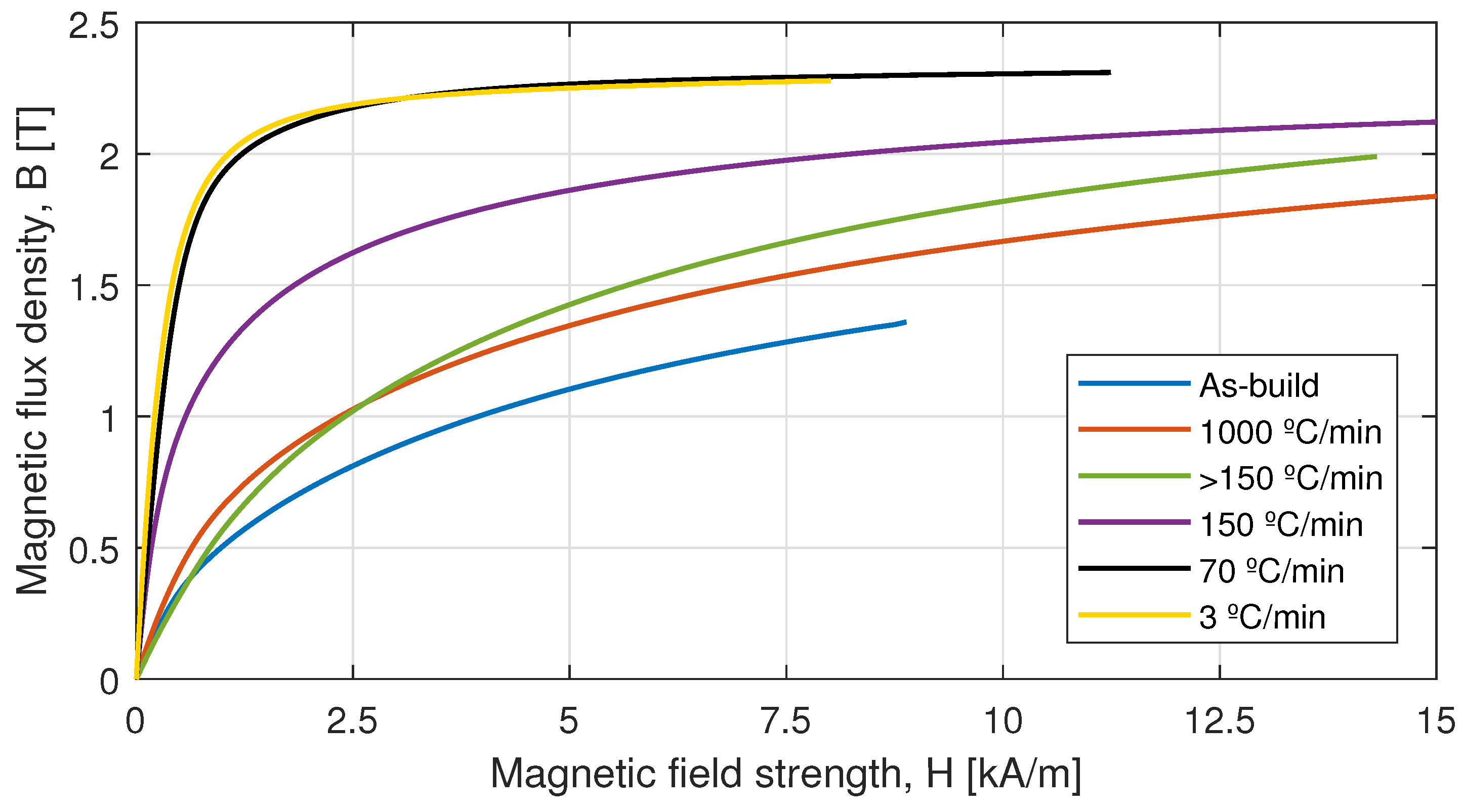
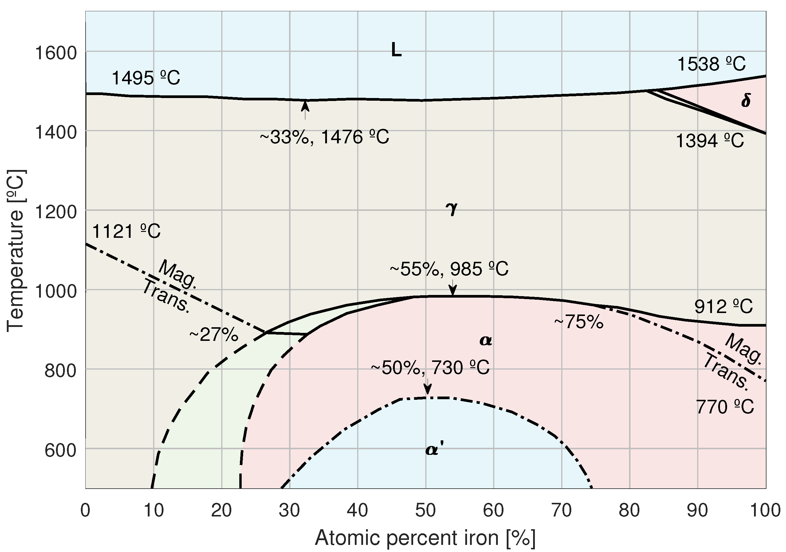
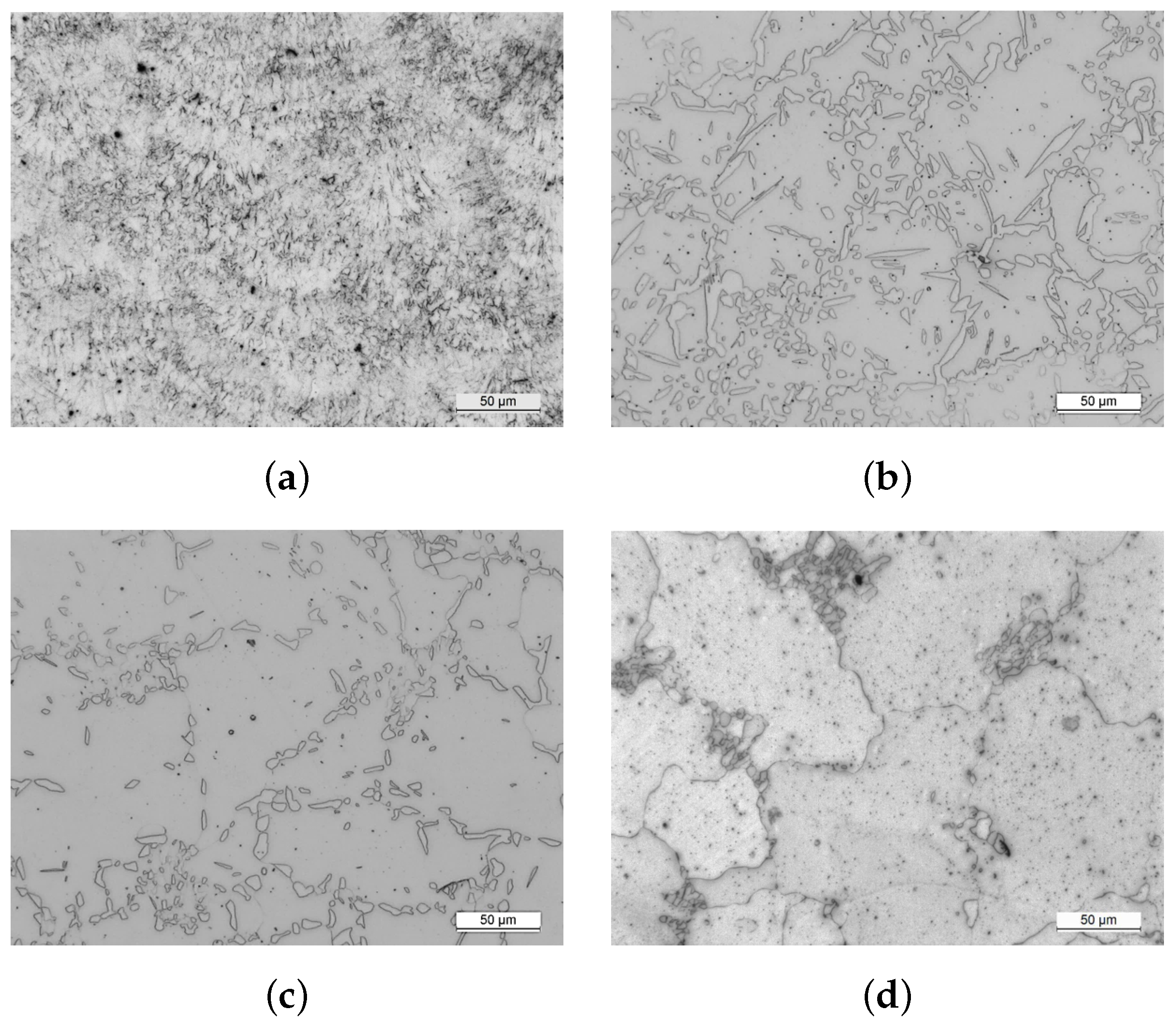
3.3. Heat Treatment Optimisation for Permendur Test Samples

This sub-section deals with the selection of the most favourable heat treatment for LPBF-processed permendur. Preliminary measurements on the AM permendur test samples confirmed that, as the literature suggests, the as-built material has excellent mechanical properties (i.e., yield strength and elongation), but poor magnetic properties. On the other hand, the reference heat treatment for iron-cobalt alloys (heating in an inert atmosphere up to 870 °C for 4 h, followed by a slow cooling of 3 °C/min [50]) resulted in excellent magnetic properties, but brittle behaviour. As the actuator parts designed in permendur are intended to have both a magnetic and a structural function, significant efforts are required to achieve a heat treatment that satisfactorily balances the magnetic and mechanical properties of the material. Specifically, the focus was placed on the cooling rate after heating the samples.
A first trial demonstrated that the holding time for the heat treatment (i.e., 12 h versus 4 h at 855 °C in an argon atmosphere) has little influence on the mechanical and magnetic properties of the permendur test samples. On the contrary, the cooling rate has a huge influence. Five different cooling rates were analysed, ranging from 3–150 °C/min (slow-cooled in furnace), to >150 °C/min with forced air cooling and around 1000 °C/min with water quenching. The results obtained for the mechanical and magnetic properties are summarised in Table 4 and Figure 6, respectively.
The variation of the magnetic and mechanical properties for permendur as a function of the cooling rate is explained by the eutectic diagram of the material, shown in Figure 7. With a composition of almost 50-50 between iron and cobalt, the significant phases for permendur are the α , with a disordered body-centred cubic (BCC) structure, and the α , with an ordered CsCl-B2 type BCC structure. The α phase has, in general terms, a very fine grain size, good mechanical properties and poor magnetic properties. The α phase, on the other hand, corresponds to a microstructure with large grains, poor mechanical properties and excellent magnetic properties.
The microstructures obtained by field emission gun scanning electron microscopy (FEG-SEM) for a number of the different applied cooling rates are shown in Figure 8. The microstructures present evident differences, with the as-built and fast-cooled (1000 °C/min) test samples exhibiting very fine grains and a disordered BCC structure, in accordance with the phase diagram. During the slow cooling (3 °C/min) process, the microstructure of the samples transforms to a fully α phase, showing larger grains. The test sample force cooled down with air at >150 °C/min presents a mix of ordered α and disordered α phases, which leads to a compromise between magnetic and mechanical properties.
In the present project, as a compromise between mechanical and magnetic properties, it was decided to continue with a cooling rate of 150 °C/min, so that the material allows for an elongation of at least 6% and the subsequent machining does not jeopardise the integrity of the additively manufactured parts.

4. Electrical Actuator Designs

This section presents two designs of the case study involving the aerospace actuator: one that has been additively manufactured and the other that is intended to be manufactured using traditional production methods for comparison purposes.

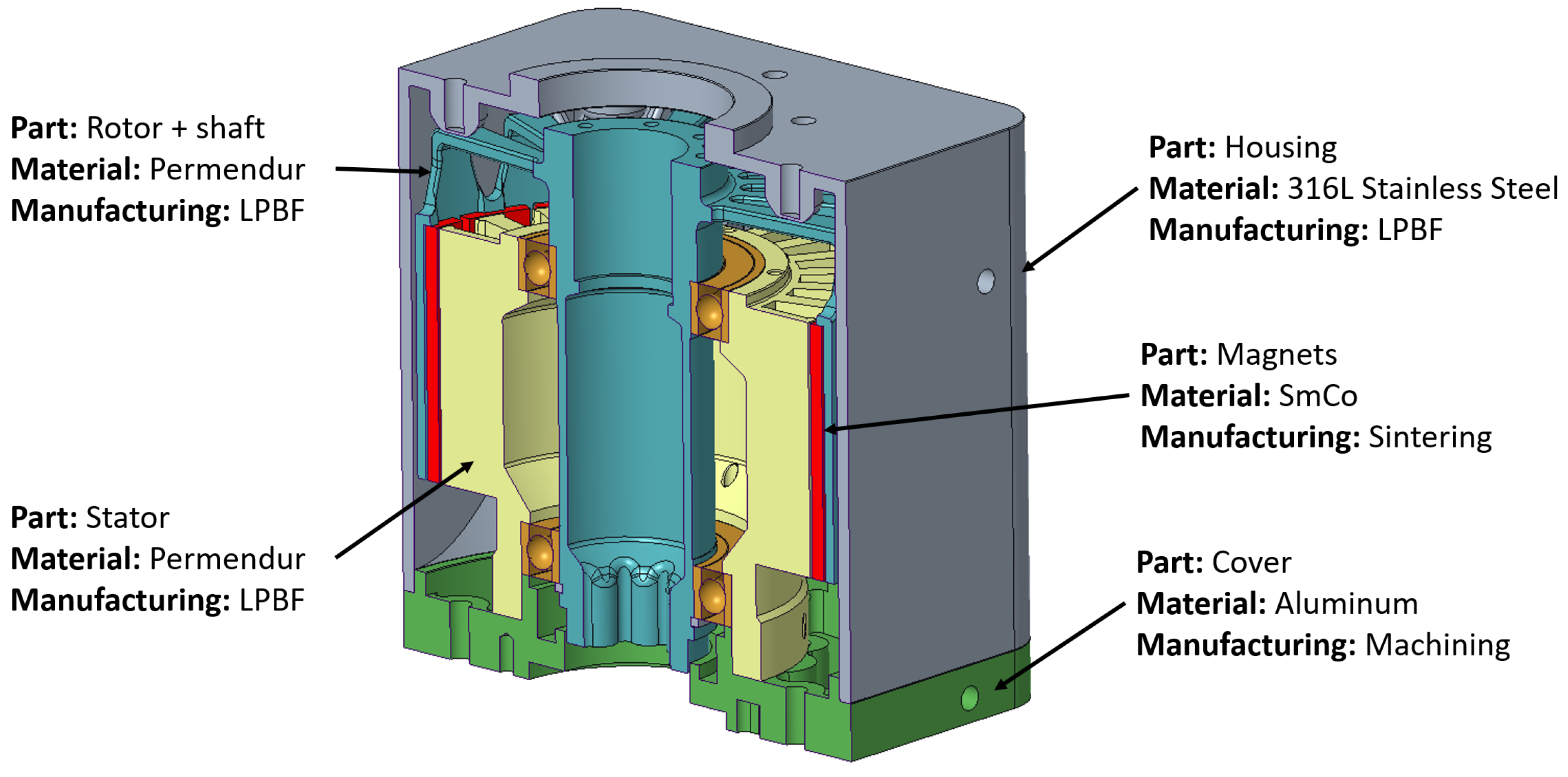
4.1. Additively Manufactured Actuator

The AM actuator design is presented in Figure 9. In this design, all parts are intended to be manufactured using LPBF, except for the rotor magnets, which are sintered; the stator coils; the bearings; and the cover, which is machined from aluminium as it has been considered that AM does not offer any advantages over conventional manufacturing for this part.
One of the advantages of AM can be appreciated in the design of the rotor and stator parts, shown in blue and yellow, respectively. Both have been designed to have a dual function, magnetic and structural, leading to a significant reduction in the number of actuator parts should the materials have just a single function. The housing was designed in 316L stainless steel, as it has no magnetic function. The resulting assembly is quite simple with just four parts, excluding the magnets and the winding.

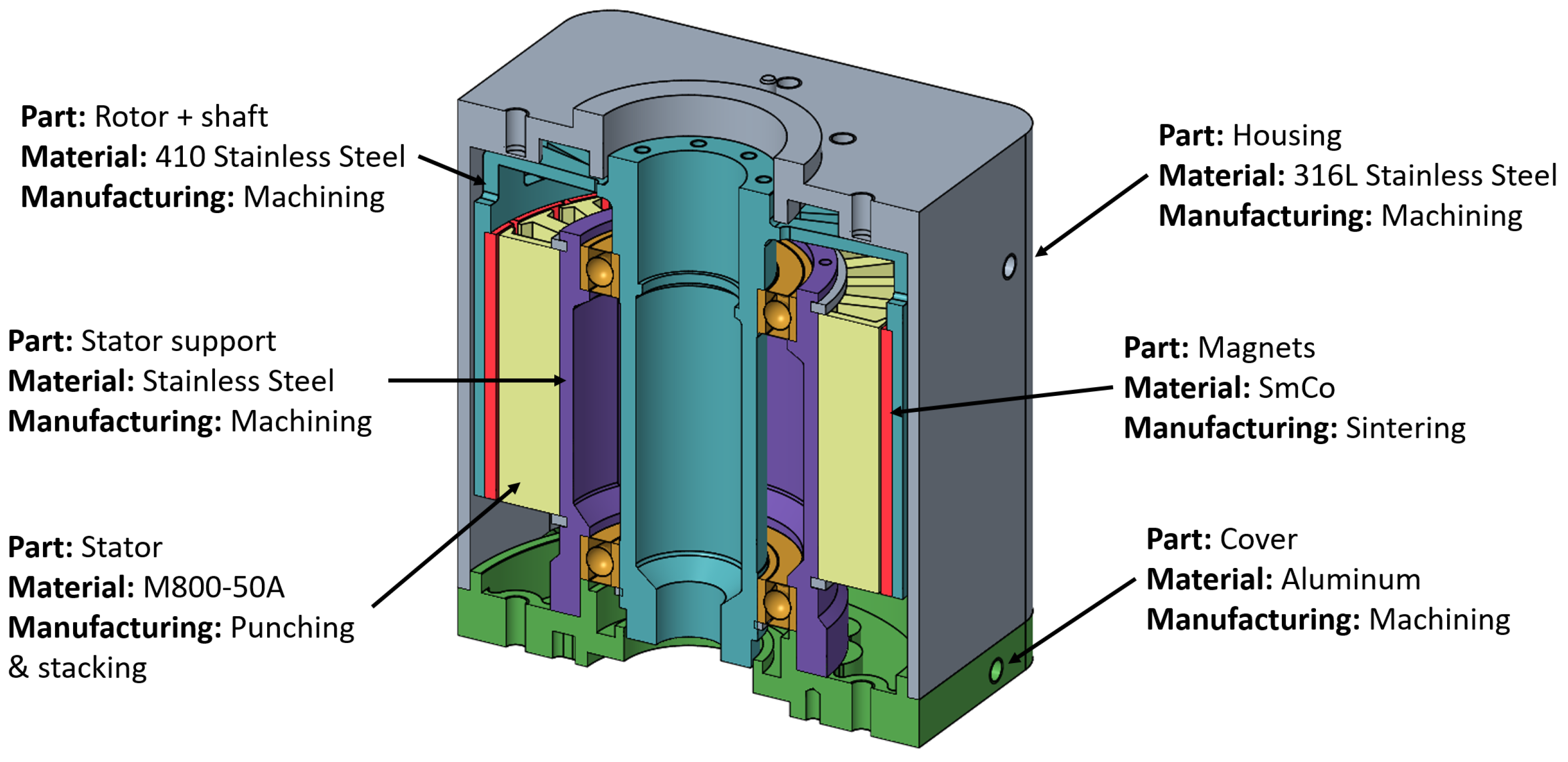
4.2. Traditionally Manufactured Actuator

In order to have a fair comparison between additive and conventional methods, a detailed model design to be manufactured by traditional methods is presented next. Firstly, the machine was designed to meet the electromagnetic requirements. Conventional high-saturation flux density M800-50A electrical steel laminations were considered for the stator part, whereas for the rotor, a 410 stainless steel was contemplated due to its reasonable magnetic characteristics and its ability to have a dual magnetic-structural function. Should a non-ferromagnetic stainless steel have been selected for the shaft, the number of parts and joints in the assembly and the level of complexity would have increased significantly. To have equivalent designs with both manufacturing methods, the traditionally manufactured actuator was designed to have the same thermal behaviour as the additively manufactured one; that is, that similar winding temperatures are achieved when providing the rated 8 N·m torque for 120 s, as required by the application (see Table 1). The thermal behaviour for both actuator models was simulated via the lumped parameter thermal network software MotorCad 2023.2.1 ® . A comparison of the winding temperatures achieved in both models is provided in Figure 10.
The reduction in the cross-sectional area of the magnetic part of the stator due to the need to include an additional support part, the lower saturation flux density of the M800-50A electrical steel compared to the permendur and the poorer axial conductivity of the laminated part as opposed to the solid permendur have required a 25% increase in the axial length of the active parts, from 44 to 55 mm, to maintain the same thermal behaviour. The final mechanical design for the traditionally manufactured actuator is presented in Figure 11.

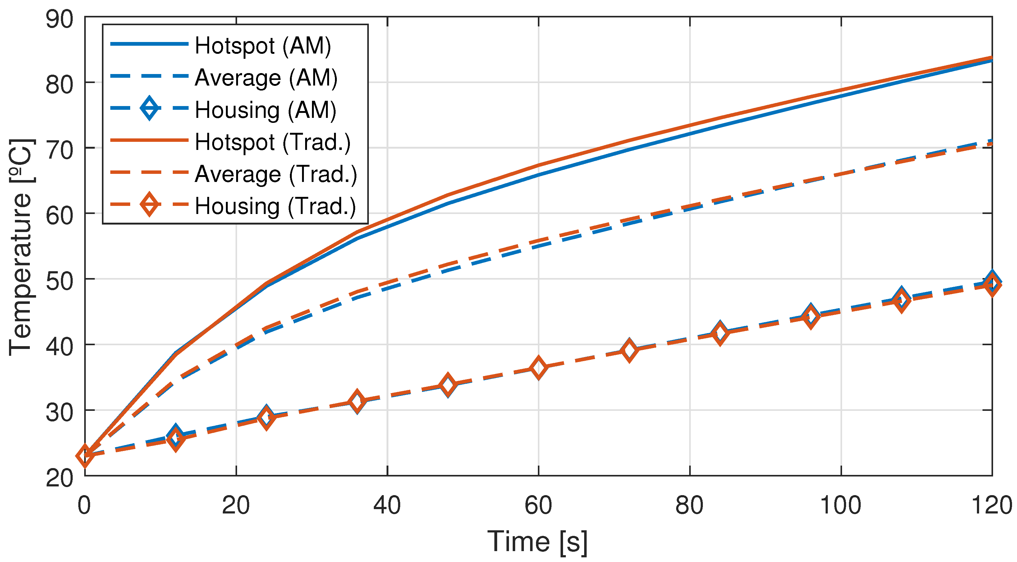
4.3. Comparative Study

The most noticeable difference between the two models is that the number of assembly parts is increased by one in the traditional design over the additively manufactured one. This aspect increases the difficulty of assembling and disassembling the actuator and reduces the reliability of the system. In addition and as mentioned above, the length of the active parts of the actuator design to be manufactured by conventional methods is 11 mm greater than that of the AM design. This implies an increase of 11% in volume and 23% in weight for the traditional concept over the AM one for the same thermal behaviour and power consumption. In fact, the actuator design intended for traditional manufacturing does not meet the application requirements in terms of design envelope. The estimated weights for the various components of both designs are given in Table 5. Although neither design meets the desired target of 3 kg, the AM design comes very close to this figure.
It is also of great interest to analyse the unitary manufacturing cost for both actuator models. The following cost analysis, presented in Table 6, is based on the assumption of having a production batch of several dozens of units per year for 10 years for both designs. Non-recurring costs have been excluded for the analysis, and due to the low number of units per year involved, a manual process instead of an automated one has been contemplated for the winding coils and magnet insertion. The costs considered in each case are the cost of materials, the cost of machine time, the machining or finishing required and the direct labour needed to assemble and complete each design. All costs are expressed as a percentage of the total manufacturing cost of a single unit of the additively manufactured actuator design.
To conclude, it is clear that the AM actuator design improves on the traditional model in terms of weight, volume and part count. Moreover, the estimated difference in cost per unit is not high, being the AM actuator design just 1.74% more expensive than the traditionally manufactured design.
The only advantage of the traditional actuator design is that there would be no torque reduction for a given current with increasing speed. While the designed actuator has a nearly zero operation speed, eddy-currents induced in the solid material at medium-to-high frequencies would make the AM design unsuitable for continuous high speed operation. A number of works in the relevant literature have tried to address the issue of iron losses in additively processed soft magnetic materials [26,35,36]. However, further advances are needed to achieve a similar performance to conventional laminated electrical steels for medium-to-high-frequency operation. Nevertheless, as this characteristic is not relevant for the application at hand as the actuator operates predominantly on standstill, the additively manufactured actuator design is regarded as superior.

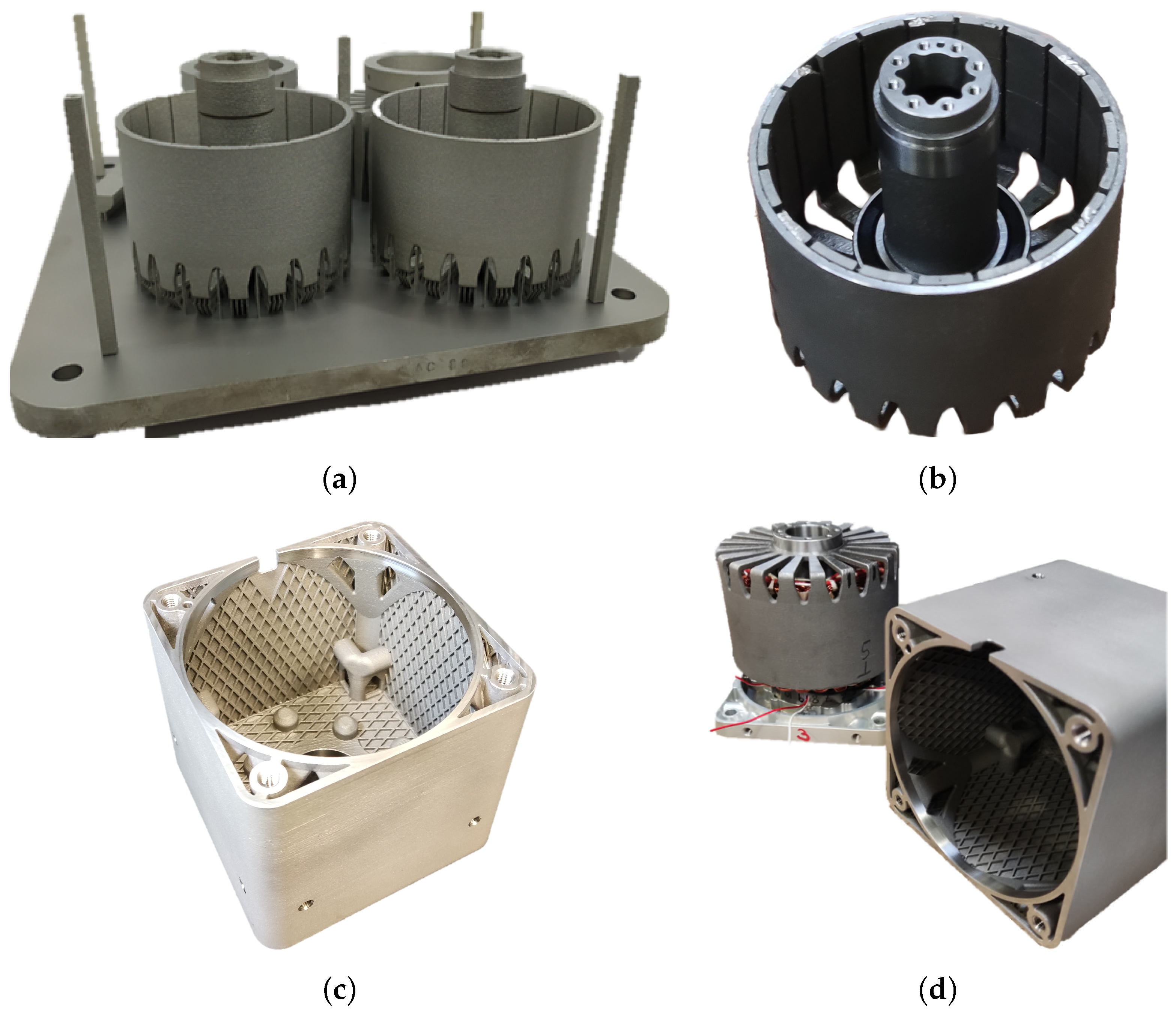
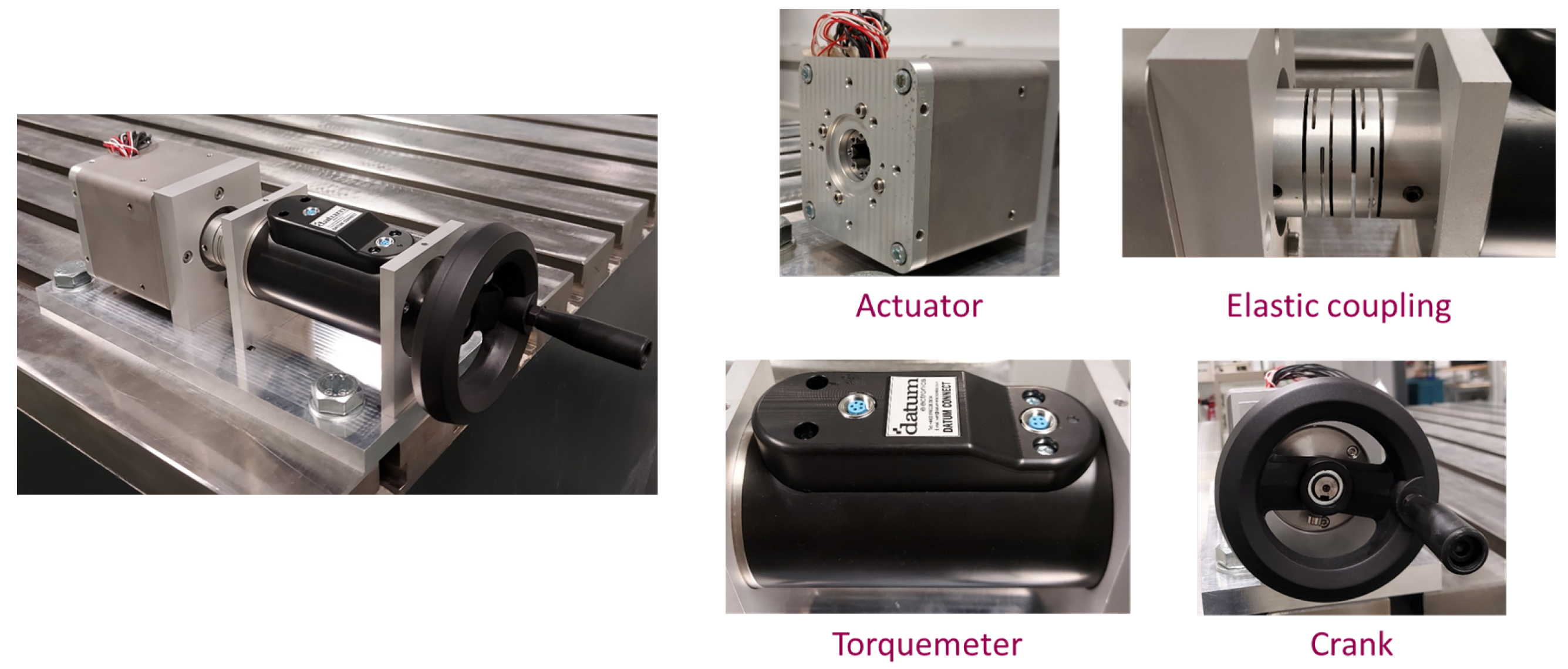
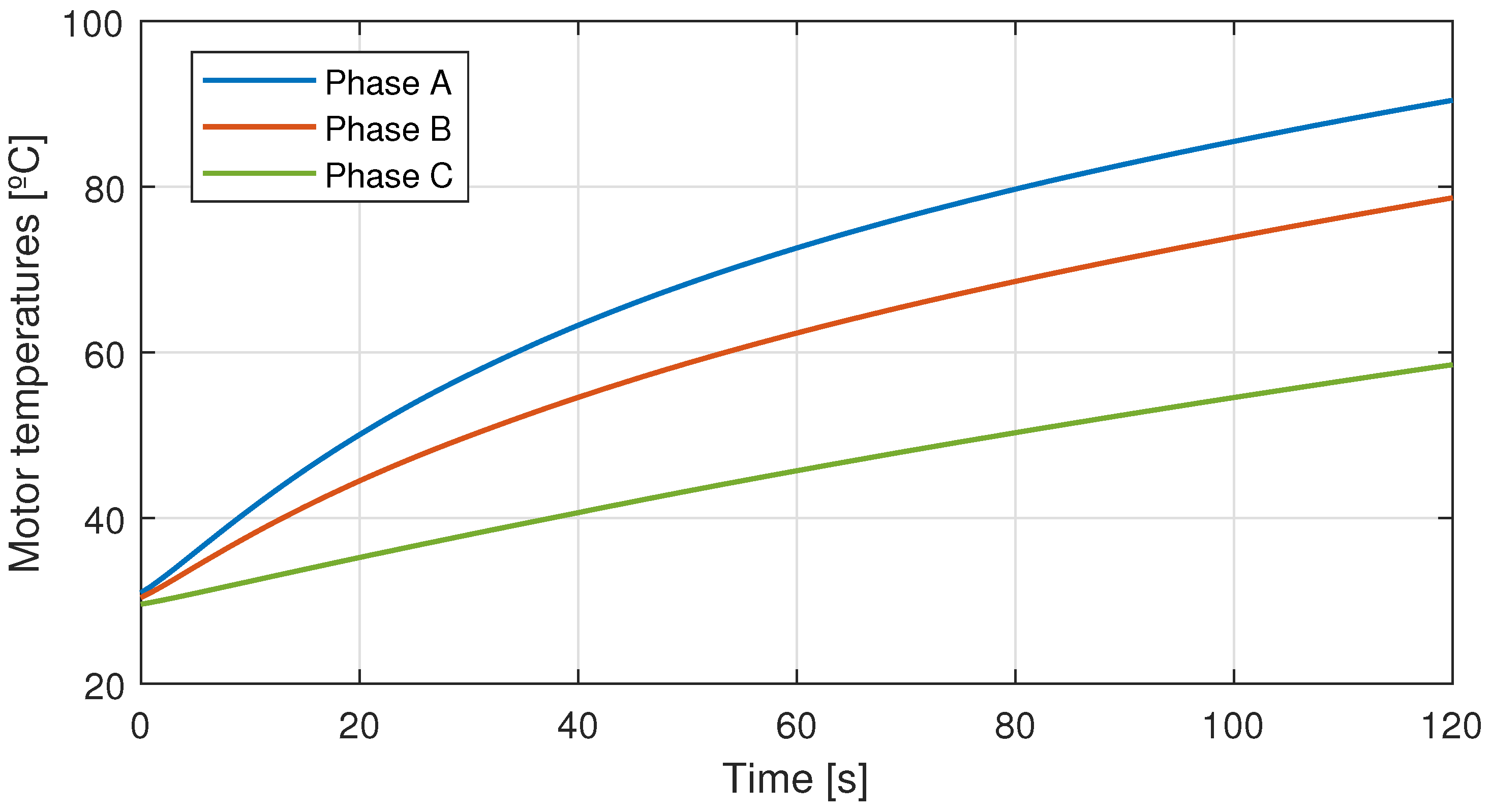
5. Manufacturing and Testing

A prototype of the AM actuator design was manufactured by Egile Mechanics via LPBF/SLM in a Renishaw AM 400 machine. After the LPBF processing of the permendur parts and the application of the heat treatment, the stator and rotor parts were separated from the corresponding baseplate via electrical discharge machining (EDM) and were sandblasted. After checking of the surface homogeneity, required machining processes such as grinding and drilling were performed and a dimensional control was established, leading to satisfactory results. Regarding the housing of the actuator, it was additively manufactured using gas-atomised 316L stainless steel powder purchased to Oerlikon. A stress relieve heat treatment according to standard AMS 2759-4 [52] was applied to the housing and, after separating it from the support, it was milled and drilled and again, compliance with required dimensions was checked. The stator part was wound with copper coils and immersed in insulating impregnation, SmCo magnets were glued to the rotor and the actuator cover was machined from an aluminium block. Finally, the full actuator prototype was assembled. The additively manufactured parts and the process of assembling the prototype are shown in Figure 12. It can be appreciated in the figure that some magnets partially broke at the outer end when removing the tooling employed to facilitate their insertion. Although this is an issue to be avoided, subsequent tests have confirmed that this fact has lead to no significant influence on the operation of the actuator, as will be discussed below.
The actuator prototype was tested in a dedicated test set up designed to verify the application requirements. This test setup is illustrated in Figure 13. Additionally, current and voltage probes to measure the power consumed by each motor phase and Pt100 temperature sensors to monitor the winding temperatures during operation were employed.
To verify the torque capability of the actuator, the rated current of 10 A R M S was supplied to the motor phases at standstill ( 2 × 10 = 14.2 A for phase A and −7.1 A for phases B and C) via a programmable switch mode DC power supply (Amrel SPS250-40). The actuator was slowly rotated by driving the crank and the readings of the torquemeter were recorded. The maximum registered value, which corresponds to the actual torque capability of the actuator for the rated current, is 8.00 N·m, which perfectly matches the design value for the actuator.
Finally, a standstill temperature test was carried out. The rated current was applied for 120 s and the temperatures in the actuator end-windings were recorded every 1 s. The results from the DC heating test are shown in Figure 14. The temperature rise for the hottest spot in the actuator is 60.4 °C, with a maximum temperature of 90.4 °C, whereas the temperature rise predicted in MotorCad ® during the design stage is of 60.8 °C, showing good agreement between the simulation models and the experimental prototype. In both cases, the maximum temperature in the actuator is well below the established maximum of 120 °C (see Table 1). During the heating test, the DC power consumption was measured as well by monitoring the current and voltage drop across each phase. The DC power consumption after the heating test is 145 W, which is 3.33% lower than the established limit of 150 W.
On completion of the performance tests on the LPBF actuator, the main requirements defined in Table 1 are considered to be fulfilled. Although the weight requisite was not satisfied, it should be noted that this requirement was considered to be very demanding from the start of the project. Nevertheless, the additively manufactured design involves a significant weight improvement over the design intended to be manufactured traditionally and over the preexisting LATM design.

6. Conclusions

This article presents the material assessment and the design of an electric aerospace actuator manufactured additively via laser powder bed fusion. Three different soft magnetic material compositions were investigated, with permendur (49Fe49Co2V) being selected as the most suitable material for the defined application. After optimising the powder bed fusion process parameters and the heat treatment that balances the mechanical and magnetic properties of the material, the designed actuator was manufactured and tested, showing good agreement between the experimental and design values and fulfilling the main design requirements. Additionally, a comparison with an actuator design intended to be manufactured via conventional means was provided. From the comparative study, it can be concluded that AM is a competitive manufacturing method for the application at hand, as the AM design improves on the traditional design in terms of weight, volume and part number, while the manufacturing cost for series production is just 1.74% higher according to a detailed cost analysis, maintaining the same performance characteristics.
The present work demonstrates that additive manufacturing can be an attractive technology for manufacturing low-frequency magnetic components (e.g., actuators, rotors) and for achieving multifunctional parts that simplify the integration and assembly of components. However, for higher-frequency applications, the losses occurring in the non-laminated materials are an issue to be addressed, as shown in previous work on the matter [26,35,36].
A limitation of the work presented is that no tests have been carried out to determine the fatigue behaviour and reliability of the parts processed by LPBF. Therefore, future work on the subject should investigate this aspect, particularly with regard to mechanical vibration and ageing due to thermal cycling. Additional points worth researching include assessing different magnetic alloys (hard and soft), testing AM technologies other than LPBF for the manufacture of electrical machines and researching into the AM of conductors.

Author Contributions

Conceptualisation, B.L., B.P. and M.A.; methodology, B.L., B.P., M.A., J.M.M., M.M.-I., E.S.J., I.G. and S.M.; software, B.L. and B.P.; validation, B.L., M.A. and I.G.; original draft preparation B.L., B.P., M.A., J.M.M., I.G. and S.M.; review and editing, M.M.-I. and E.S.J.; project administration, M.M.-I. and E.S.J.; funding acquisition, M.M.-I., B.P., M.A., J.M.M., E.S.J. and I.G. All authors have read and agreed to the published version of the manuscript.

Funding

This research was funded by the European Union’s Clean Sky 2 Joint Undertaking programme under topic JTI-CS2-2018-CfP09-SYS-02-56 and grant agreement ID 865206.

Data Availability Statement

The data presented in this study are available on request from the corresponding author. The data are not publicly available for confidentiality reasons.

Acknowledgments

The authors are grateful to Safran Electronics & Defense as Topic Manager of the corresponding Clean Sky 2 project and to Lancor 2000 S.Coop for their help in manufacturing the actuator prototype.

Conflicts of Interest

The authors declare no conflict of interest.

Abbreviations

The following abbreviations are used in this manuscript:
AMAdditive Manufacturing
BCCBody-Centred Cubic
DCDirect Current
DoEDesign of Experiments
EDMElectrical Discharge Machining
FEGField Emission Gun
HTHeat Treatment
ICPInductive Coupled Plasma
LPBFLaser Powder Bed Fusion
MPIFMetal Powder Industries Federation
OESOptical Emission Spectrometry
PBFPowder Bed Fusion
SEMScanning Electron Microscopy
SLMSelective Laser Melting
SLSSelective Laser Sintering
VSMVibrating Sample Magnetometer

References

  1. Mohamed, M.A.A.; Yeoh, S.S.; Atkin, J.; Hussaini, H.; Bozhko, S. Efficiency Focused Energy Management Strategy Based on Optimal Droop Gain Design for More Electric Aircraft. IEEE Trans. Transp. Electrif. 2022, 8, 4205–4218. [Google Scholar] [CrossRef]
  2. Orme, M.E.; Gschweitl, M.; Ferrari, M.; Vernon, R.; Madera, I.J.; Yancey, R.; Mouriaux, F. Additive Manufacturing of Lightweight, Optimized, Metallic Components Suitable for Space Flight. J. Spacecr. Rocket. 2017, 54, 1050–1059. [Google Scholar] [CrossRef]
  3. Meng, L.; Zhang, W.; Quan, D.; Shi, G.; Tang, L.; Hou, Y.; Breitkopf, P.; Zhu, J.; Gao, T. From Topology Optimization Design to Additive Manufacturing: Today’s Success and Tomorrow’s Roadmap. Arch. Comput. Methods Eng. 2020, 27, 805–830. [Google Scholar] [CrossRef]
  4. Paul, G.; Omar, M.; Nathan, A. Intro to additive manufacturing for propulsion systems. In Proceedings of the AIAA Joint Propulsion Conference, Cincinnati, OH, USA, 9–11 July 2018; p. 83. [Google Scholar]
  5. Steffen, D. Case Study: Additive Manufacturing. 3D Printing a Rocket Engine. Available online: https://www.etmm-online.com/3d-printing-a-rocket-engine-a-886960/ (accessed on 10 February 2023).
  6. Werkheiser, N. Overview of NASA Initiatives in 3D Printing and Additive Manufacturing. In Proceedings of the 2014 DoD Maintenance Symposium, Birmingham, AL, USA, 17–20 November 2014. [Google Scholar]
  7. Barroqueiro, B.; Andrade-Campos, A.; Valente, R.A.F.; Neto, V. Metal Additive Manufacturing Cycle in Aerospace Industry: A Comprehensive Review. J. Manuf. Mater. Process. 2019, 3, 52. [Google Scholar] [CrossRef]
  8. Blakey-Milner, B.; Gradl, P.; Snedden, G.; Brooks, M.; Pitot, J.; Lopez, E.; Leary, M.; Berto, F.; du Plessis, A. Metal additive manufacturing in aerospace: A review. Mater. Des. 2021, 209, 110008. [Google Scholar] [CrossRef]
  9. Chen, W.; Li, Z. Additive Manufacturing of Titanium Aluminides; Elsevier: Amsterdam, The Netherlands, 2019; pp. 235–263. [Google Scholar] [CrossRef]
  10. Woolley, S. Hot Stuff: To Build More Affordable Rocket Engines, NASA Researchers Are Using the Latest 3D Printers — And 1 Ancient Metal. Available online: https://www.ge.com/news/reports/hot-stuff-to-build-more-affordable-rocket-engines-nasa-researchers-are-using-the-latest-3d-printers-and-1-ancient-metal (accessed on 10 February 2023).
  11. 3D Print, NASA Advances New Alloys and Scale of Metal Additive Manufacturing. Available online: https://3dprint.com/278670/nasa-advances-new-alloys-and-scale-of-metal-additive-manufacturing/ (accessed on 10 February 2023).
  12. Zaharia, S.M.; Pop, M.A.; Buican, G.R.; Chicos, L.A.; Stamate, V.M.; Pascariu, I.S.; Lancea, C. Design and Testing of Brushless DC Motor Components of A6 Steel Additively Manufactured by Selective Laser Sintering. Aerospace 2023, 10, 60. [Google Scholar] [CrossRef]
  13. Wu, F.; EL-Refaie, A.M.; Al-Qarni, A. Minimization of Winding AC Losses Using Inhomogeneous Electrical Conductivity Enabled by Additive Manufacturing. IEEE Trans. Ind. Appl. 2022, 58, 3447–3458. [Google Scholar] [CrossRef]
  14. Wrobel, R.; Hussein, A. A Feasibility Study of Additively Manufactured Heat Guides for Enhanced Heat Transfer in Electrical Machines. IEEE Trans. Ind. Appl. 2020, 56, 205–215. [Google Scholar] [CrossRef]
  15. Kaur, I.; Singh, P. State-of-the-art in heat exchanger additive manufacturing. Int. J. Heat Mass Transf. 2021, 178, 121600. [Google Scholar] [CrossRef]
  16. Robinson, A.; Colenbrander, J.; Deaville, T.; Durfee, J.; Kempers, R. A wicked heat pipe fabricated using metal additive manufacturing. Int. J. Thermofluids 2021, 12, 100117. [Google Scholar] [CrossRef]
  17. Wu, F.; EL-Refaie, A.M.; Al-Qarni, A. Additively Manufactured Hollow Conductors for High Specific Power Electrical Machines: Aluminum vs Copper. In Proceedings of the 2021 IEEE Energy Conversion Congress and Exposition (ECCE), Vancouver, BC, Canada, 10–14 October 2021; pp. 4397–4404. [Google Scholar] [CrossRef]
  18. Wu, F.; EL-Refaie, A.M.; Al-Qarni, A. Additively Manufactured Hollow Conductors Integrated With Heat Pipes: Design Tradeoffs and Hardware Demonstration. IEEE Trans. Ind. Appl. 2021, 57, 3632–3642. [Google Scholar] [CrossRef]
  19. Selema, A.; Ibrahim, M.N.; Sergeant, P. Additively-Manufactured Ultra-Light Shaped-Profile Windings for HF Electrical Machines and Weight-Sensitive Applications. IEEE Trans. Transp. Electrif. 2022, 8, 4313–4324. [Google Scholar] [CrossRef]
  20. Simpson, N.; North, D.J.; Collins, S.M.; Mellor, P.H. Additive Manufacturing of Shaped Profile Windings for Minimal AC Loss in Electrical Machines. IEEE Trans. Ind. Appl. 2020, 56, 2510–2519. [Google Scholar] [CrossRef]
  21. Selema, A.; Ibrahim, M.N.; Sergeant, P. Development of Novel Semi-Stranded Windings for High Speed Electrical Machines Enabled by Additive Manufacturing. Appl. Sci. 2023, 13, 1653. [Google Scholar] [CrossRef]
  22. Hosek, M.; Krishnasamy, J.; Sah, S.; Bashaw, T. Spray-Formed Hybrid-Field Electric Motor; American Society of Mechanical Engineers: Charlotte, NC, USA, 21–24 August 2016. [Google Scholar] [CrossRef]
  23. National Science Foundation, Catalyzing Commercialization: Spray-Formed Magnetic Composite Radically Improves Electric Motor Performance. Available online: https://www.aiche.org/resources/publications/cep/2016/february/catalyzing-commercialization-spray-formed-magnetic-composite-radically-improves-electric-motor (accessed on 10 February 2023).
  24. Freeman, F.S.; Lincoln, A.; Sharp, J.; Lambourne, A.; Todd, I. Exploiting thermal strain to achieve an in-situ magnetically graded material. Mater. Des. 2019, 161, 14–21. [Google Scholar] [CrossRef]
  25. Kresse, T.; Schurr, J.; Lanz, M.; Kunert, T.; Schmid, M.; Parspour, N.; Schneider, G.; Goll, D. Additively Manufactured Transverse Flux Machine Components with Integrated Slits for Loss Reduction. Metals 2022, 12, 1875. [Google Scholar] [CrossRef]
  26. Tiismus, H.; Kallaste, A.; Naseer, M.U.; Vaimann, T.; Rassolkin, A. Design and Performance of Laser Additively Manufactured Core Induction Motor. IEEE Access 2022, 10, 50137–50152. [Google Scholar] [CrossRef]
  27. Garibaldi, M. Laser Additive Manufacturing of Soft Magnetic Cores for Rotating Electrical Machinery: Materials Development and Part Design. Ph.D. Thesis, University of Nottingham, Nottingham, UK, 2018. [Google Scholar]
  28. Kallaste, A.; Vaimann, T.; Rassalkin, A. Additive Design Possibilities of Electrical Machines; IEEE: Piscataway Township, NJ, USA, 2018; pp. 1–5. [Google Scholar] [CrossRef]
  29. Gargalis, L.; Madonna, V.; Giangrande, P.; Rocca, R.; Hardy, M.; Ashcroft, I.; Galea, M.; Hague, R. Additive Manufacturing and Testing of a Soft Magnetic Rotor for a Switched Reluctance Motor. IEEE Access 2020, 8, 206982–206991. [Google Scholar] [CrossRef]
  30. Urbanek, S.; Frey, P.; Magerkohl, S.; Zimmer, D.; Tasche, L.; Schaper, M.; Ponick, B. Design and Experimental Investigation of an Additively Manufactured PMSM Rotor; IEEE: Piscataway Township, NJ, USA, 2021; pp. 1–6. [Google Scholar] [CrossRef]
  31. Zhang, Z.Y.; Jhong, K.J.; Cheng, C.W.; Huang, P.W.; Tsai, M.C.; Lee, W.H. Metal 3D Printing of Synchronous Reluctance Motor; IEEE: Piscataway Township, NJ, USA, 2016; pp. 1125–1128. [Google Scholar] [CrossRef]
  32. Tseng, G.M.; Jhong, K.J.; Tsai, M.C.; Huang, P.W.; Lee, W.H. Application of Additive Manufacturing for Low Torque Ripple of 6/4 Switched Reluctance Motor. In Proceedings of the 2016 19th International Conference on Electrical Machines and Systems (ICEMS), Chiba, Japan, 2 February 2017; pp. 1–4. [Google Scholar]
  33. Metsä-Kortelainen, S.; Lindroos, T.; Savolainen, M.; Jokinen, A.; Revuelta, A.; Pasanen, A.; Ruusuvuori, K.; Pippuri, J. Manufacturing of topology optimized soft magnetic core through 3D printing. In NAFEMS Exploring the Design Freedom of Additive Manufacturing through Simulation; VTT Technical Research Centre of Finland Ltd.: Helsinki, Finland, 2016. [Google Scholar]
  34. Clean Sky 2 Call for Proposals 09 (H2020-CS2-CFP09-2018-02), JTI-CS2-2018-CfP09-SYS-02-56: Additive Manufacturing Magnetic Motor. Available online: https://www.cleansky.eu/calls (accessed on 10 February 2023).
  35. Plotkowski, A.; Pries, J.; List, F.; Nandwana, P.; Stump, B.; Carver, K.; Dehoff, R.R. Influence of scan pattern and geometry on the microstructure and soft-magnetic performance of additively manufactured Fe-Si. Addit. Manuf. 2019, 29, 100781. [Google Scholar] [CrossRef]
  36. Tiismus, H.; Kallaste, A.; Belahcen, A.; Rassolkin, A.; Vaimann, T.; Ghahfarokhi, P.S. Additive Manufacturing and Performance of E-Type Transformer Core. Energies 2021, 14, 3278. [Google Scholar] [CrossRef]
  37. Singh, S.; Payarou, T.; Boby, M.; Lamarre, J.M.; Bernier, F.; Ibrahim, M.; Pillay, P. Cold Spray Additive Manufacturing of a Petal Shaped Surface Permanent Magnet Traction Motor. IEEE Trans. Transp. Electrif. 2023. [Google Scholar] [CrossRef]
  38. Lamarre, J.M.; Bernier, F. Permanent Magnets Produced by Cold Spray Additive Manufacturing for Electric Engines. J. Therm. Spray Technol. 2019, 28, 1709–1717. [Google Scholar] [CrossRef]
  39. Boby, M.; Singh, S.; Lamarre, J.M.; Ibrahim, M.; Bernier, F.; Pillay, P. In-Situ Magnetization of a Cold Sprayed Permanent Magnet Rotor Using an Impulse Magnetizer. In Proceedings of the IECON 2021—47th Annual Conference of the IEEE Industrial Electronics Society, Toronto, ON, Canada, 13–16 October 2021; pp. 1–6. [Google Scholar] [CrossRef]
  40. White, E.M.H.; Kassen, A.G.; Simsek, E.; Tang, W.; Ott, R.T.; Anderson, I.E. Net Shape Processing of Alnico Magnets by Additive Manufacturing. IEEE Trans. Magn. 2017, 53, 1–6. [Google Scholar] [CrossRef]
  41. Huang, J.; Yung, K.C.; Ang, D.T.C. Magnetic properties of SmCo5 alloy fabricated by laser sintering. J. Mater. Sci. Mater. Electron. 2019, 30, 11282–11290. [Google Scholar] [CrossRef]
  42. Paranthaman, M.P.; Yildirim, V.; Lamichhane, T.N.; Begley, B.A.; Post, B.K.; Hassen, A.A.; Sales, B.C.; Gandha, K.; Nlebedim, I.C. Additive Manufacturing of Isotropic NdFeB PPS Bonded Permanent Magnets. Materials 2020, 13, 3319. [Google Scholar] [CrossRef] [PubMed]
  43. Pigliaru, L.; Rinaldi, M.; Ciccacci, L.; Norman, A.; Rohr, T.; Ghidini, T.; Nanni, F. 3D printing of high performance polymer-bonded PEEK-NdFeB magnetic composite materials. Funct. Compos. Mater. 2020, 1, 4. [Google Scholar] [CrossRef]
  44. Yule, A.; Dunkley, J. Atomization of Melts: For Powder Production and Spray Deposition; Oxford University Press: Oxford, UK, 1994. [Google Scholar]
  45. Urionabarrenetxea, E.; Martín, J.M.; Avello, A.; Rivas, A. Simulation and validation of the gas flow in close-coupled gas atomisation process: Influence of the inlet gas pressure and the throat width of the supersonic gas nozzle. Powder Technol. 2022, 407, 117688. [Google Scholar] [CrossRef]
  46. Firdosy, S.A.; Ury, N.E.; Witt, R.; Dillon, R.P.; Ravi, V.A. Laser-Deposited Soft Magnetic Fe–Ni–Mo Alloy: A Processing—Microstructure Study. Metallogr. Microstruct. Anal. 2022, 11, 108–118. [Google Scholar] [CrossRef]
  47. Ouyang, G.; Chen, X.; Liang, Y.; Macziewski, C.; Cui, J. Review of Fe-6.5 wt%Si high silicon steel—A promising soft magnetic material for sub-kHz application. J. Magn. Magn. Mater. 2019, 481, 234–250. [Google Scholar] [CrossRef]
  48. Zaied, M.; Ospina-Vargas, A.; Favergeon, J.; Fenineche, N. Additive Manufacturing of Soft Ferromagnetic Fe6.5%Si Annular Cores: Process Parameters and Magnetic Properties. IEEE Trans. Magn. 2022, 58, 1–9. [Google Scholar] [CrossRef]
  49. Kurita, H.; Lohmuller, P.; Laheurte, P.; Nakajima, K.; Narita, F. Additive manufacturing and energy-harvesting performance of honeycomb-structured magnetostrictive Fe52–Co48 alloys. Addit. Manuf. 2022, 54, 102741. [Google Scholar] [CrossRef]
  50. Carpenter Electrification: Hiperco® 50A, Specification for Heat Treatment. Original Document from Harris Semiconductor. 2020. Available online: https://www.carpenterelectrification.com/hiperco-50a-datasheet50 (accessed on 22 May 2023).
  51. Nishizawa, T.; Ishida, K. The Co-Fe (Cobalt-Iron) system. Bull. Alloy. Phase Diagrams 1984, 5, 250–259. [Google Scholar] [CrossRef]
  52. AMS2759/4; Heat Treatment, Austenitic Corrosion-Resistant Steel Parts. SAE International: Warrendale, PA, USA, 2011. Available online: https://www.sae.org/standards/content/ams2759/4/ (accessed on 19 July 2023).
Figure 1. Smart Active Inceptor concept by Safran Electronics & Defense [34].
Aerospace 10 00813 g001
Figure 2. (a) Schematic diagram of the primary atomisation of a melt stream by the rapidly expanding gas; (b) photograph showing the proximity between the gas and the melt exits [45] (reproduced with permission from the authors).
Aerospace 10 00813 g002
Figure 3. Magnetisation curves for the characterised powder at room temperature.
Aerospace 10 00813 g003
Figure 4. LPBF parameter development process for the Fe6.5Si alloy.
Aerospace 10 00813 g004
Figure 5. LPBF parameter development process for the permendur alloy.
Aerospace 10 00813 g005
Figure 6. Mean magnetisation curve (1st quadrant) for the permendur test samples according to the applied cooling rate.
Aerospace 10 00813 g006
Figure 7. Phase diagram for permendur (redrawn from data from [51]).
Aerospace 10 00813 g007
Figure 8. Microstructures exhibited by permendur test samples for different cooling rates after heat treatment: (a) as-built; (b) 1000 °C/min (water-quenched); (c) >150 °C/min (air-cooled); (d) 3 °C/min (cooled inside furnace).
Aerospace 10 00813 g008
Figure 9. Additively manufactured actuator design.
Aerospace 10 00813 g009
Figure 10. Winding temperatures in the AM (blue) and traditionally manufactured (red) actuator model estimated in MotorCad ® .
Aerospace 10 00813 g010
Figure 11. Traditionally manufactured actuator design.
Aerospace 10 00813 g011
Figure 12. Prototype manufacturing: (a) as-built parts; (b) rotor and magnets; (c) casing; (d) assembling.
Aerospace 10 00813 g012
Figure 13. Test bench configuration.
Aerospace 10 00813 g013
Figure 14. Temperatures in the stator end-windings registered during the standstill heating test on the actuator.
Aerospace 10 00813 g014
Table 1. Main requirements for the designed actuator.
Requirements
Envelope100 × 100 × 100 mm
Torque8 N·m
Max. power consumption (stall conditions)150 W
Max. temperature after 120 s operation (stall)120 °C
Max. weight3 kg
Table 2. Magnetic properties of the gas-atomised soft magnetic powders at room temperature: B s : induction saturation; H c : coercivity; H K : anysotropy field.
Sample B s (T) H c (kA/m) H K (kA/m)
Supermalloy 20–65 µm0.7460.061103.5
Fe6.5Si 15–45 µm1.7670.313273.7
Permendur 20–63 µm2.1782.928330.2
Table 3. Physical properties of the gas-atomised soft magnetic powders.
    Sample  Flow Rate
(s/50 g)
Apparent
Density
(g/cm 3 )
Tap
Density
(g/cm 3 )
Pycnometer
Density
(g/cm 3 )
  Hausner
Ratio
SupermalloyNo flow4.455.338.61.20
Fe6.5Si19.73.894.547.41.17
PermendurNo flow4.455.198.11.16
Table 4. Mechanical properties for the permendur test samples according to the applied cooling rate.
     Treatment Cooling
Rate
[°C/min]
Ultimate
Tensile
Strength
[MPa]
Yield
Strength
[MPa]
    Elongation
[%]
As-built-92485216.5
HT: 855 °C / Ar / 4 h1000 1 85454320.0
>150 2 64529610.0
150 3 6593326.0
70 3 4493023.6
3 3 3402621.7
1 Water-quenched; 2 air-cooled; 3 cooled inside furnace.
Table 5. Weight comparison between the AM and conventionally manufactured actuator designs.
PartLBPFTraditional
Stator0.82 kg0.62 kg (lamination)
0.395 kg (support)
Magnets0.22 kg0.16 kg
Endcap0.16 kg0.16 kg
Retaining rings0.00 kg0.01 kg
Ball bearings0.03 kg0.03 kg
Rotor0.56 kg0.68 kg
Casing1.11 kg1.67 kg
Winding0.36 kg0.27 kg
Total3.26 kg4.01 kg
Table 6. Cost analysis for the AM and traditionally manufactured actuator designs.
Manufact.
Method
  Material  LBPF + HTPunching
and Stacking
Machining
+ HT
  Labour  Subtotal
RotorAM1.58%22.16%0.00%4.92%0.00%28.66%
Traditional2.32%0.00%0.00%19.51%1.62%23.45%
StatorAM1.51%21.93%0.00%4.25%0.00%27.68%
Traditional0.18%0.00%7.57%0.36%0.45%8.57%
Stator
support
AM0.00%0.00%0.00%0.00%0.00%0.00%
Traditional0.60%0.00%0.00%16.66%1.40%18.66%
HousingAM0.25%14.41%0.00%3.70%0.00%18.37%
Traditional2.70%0.00%0.00%17.63%1.51%21.84%
EndcapAM0.02%0.00%0.00%0.76%0.00%0.78%
Traditional0.02%0.00%0.00%0.76%0.00%0.78%
WindingsAM0.51%0.00%0.00%0.00%7.71%8.22%
Traditional0.38%0.00%0.00%0.00%8.08%8.46%
MagnetsAM1.00%0.00%0.00%0.00%1.63%2.63%
Traditional0.80%0.00%0.00%0.00%2.04%2.83%
Integration
and testing
AM0.00%0.00%0.00%0.00%13.65%13.65%
Traditional0.00%0.00%0.00%0.00%13.65%13.65%
TotalAM100.00%
Traditional98.26%
Disclaimer/Publisher’s Note: The statements, opinions and data contained in all publications are solely those of the individual author(s) and contributor(s) and not of MDPI and/or the editor(s). MDPI and/or the editor(s) disclaim responsibility for any injury to people or property resulting from any ideas, methods, instructions or products referred to in the content.

