1. Introduction
The scramjet engine is currently the most studied air-breathing propulsion technology for hypersonic vehicle development. For the study of these vehicles, experimental and numerical studies are being actively conducted through various visualization techniques, wall pressure measurement, and efficient analysis solver development [
1,
2,
3,
4,
5]. While there are numerous studies related to scramjet, the primary challenge is achieving reliable ignition and combustion stabilization. The scramjet combustor’s flow residence time in hypersonic flight above Mach 5 is very short, ranging from 0.1 to 1.0 ms, leaving only about 1 ms for fuel injection, fuel–air mixing, and ignition. At the low end of hypersonic flight, i.e., a flight Mach number of 5.0–8.0, low stagnation temperatures at the combustor entrance can cause insufficient ignition, which is a significant problem. Therefore, proper design, analysis and experimental research according to target flight conditions are absolutely necessary.
Liu et al. have classified recent research trends in scramjet combustion stabilization technology, aimed at addressing ignition and combustion issues, into four major categories [
6]. These categories are (1) flow mixing enhancement through the generation of vortex and turbulence; (2) physical flame holding techniques, such as increasing flow residence time by applying recesses like cavity flame-holders; (3) energetic enhancement by local enhancement methods, such as plasma or spark; and (4) shock-induced combustion through the generation of radicals. Various approaches and schemes can be categorized into passive or active methods. Active methods, such as pulsed jet injection, pulsed detonation, and plasma intensified techniques, have been studied to improve mixing and stable ignition [
7,
8,
9,
10]. Conversely, a geometrical approach, such as applying recesses corresponding to cavities, steps, or struts, has been conventionally proposed as a passive method. Variables representing the shape of these cavities can usually be expressed as depth (D), length-to-depth ratio (L/D), and ramp angle (α), as shown in
Figure 1. L/D, the most basic design variable in cavity design, determines the fundamental flow characteristics of the cavity. An L/D of 7–10 is an open cavity, with the upstream shear layer reattached at the edge downstream of the cavity. When the L/D is 10–13, it is a closed cavity, and the shear layer is attached to the bottom of the middle of the cavity; it collides with the rear wall as a whole, and the shock wave increases the pressure and greatly increases the drag. In particular, in the open cavity region, there is a transition area of the oscillation mechanism. When a cavity is exposed to a flow, self-sustaining oscillations occur that cause perturbations in pressure, density, and velocity. Cavities with no ramp angle and an L/D below the range of 2–3 are controlled by the transverse oscillation mechanism, but with larger L/D, longitudinal oscillation becomes the dominant mechanism. [
11]. Davis et al. studied the effect of cavity shape change on the flow residence time and confirmed that the residence time decreased as the cavity depth decreased [
12]. Ren et al. have confirmed that the acoustic pressure level tends to concentrate in the vertical direction of the cavity when a ramp angle exists [
13]. In addition, Thakur et al. conducted research on a step-based scramjet combustor, and Li et al. conducted a numerical study on a scramjet combustor with a novel strut configuration [
14,
15].
Cavities are commonly used as flame-holders in scramjet combustors due to the recirculation zone they generate within the supersonic flow of the mainstream, which increases the overall flow residence time and creates favorable flame stabilization conditions [
16]. Meng et al. conducted an experimental study of a single-cavity flame-holder scramjet combustor using three different equivalence ratios of ethylene fuel. Based on chemiluminescence images and pressure characteristics, three different combustion modes were identified: cavity shear layer, jet wake, and jet front [
17]. Cai et al. investigated the flame stabilization process in a hydrogen-fueled scramjet combustor with a rear wall expansion cavity through optical and wall pressure measurements at a Mach 2.92 direct-connect ground test facility. They also investigated four different fuel injection methods and found that using two cascaded injectors and two parallel injectors achieved more intense and stable combustion in the combustor than using single injectors. A wedge-shaped flame was also observed, resulting from an injection 30 mm upstream of the cavity [
18].
Over time, researchers have proposed various methods for using cavity flame holders, and both numerical analyses and experimental studies have been conducted to explore the effects of the number of cavities. For example, Collatz et al. conducted an experimental study and a corresponding numerical study to compare the use of a single-cavity flame holder with that of two opposing cavities (dual cavity) in a direct-connect supersonic combustion flow facility, which simulated flight Mach numbers of 3.5~5.0. The dual cavity consistently showed higher peak pressure and combustor exit pressure ratios due to the additional heat released in combustion, indicating that the dual cavity flow path provided better combustion and performance than a single cavity. Furthermore, the dual cavity had a 72% higher stream thrust compared to the single cavity across all cases. However, the position of the shock wave was located further upstream in the isolator compared to the single cavity as the equivalence ratio increased, and the operability window of the flow path became smaller. Therefore, the operability range of the dual cavity was narrower than that of the single cavity, but the overall performance was improved in the dual cavity, which showed a higher pressure ratio and stream thrust at the same equivalence ratio [
19]. Li et al. conducted an experimental study to investigate ignition enhancement mechanisms in a scramjet combustor using a dual-cavity configuration with isolator entrance conditions of Mach 2.52, a total pressure of 1.6 MPa, and a stagnation temperature of 1486 K. The study found that the cavity flame, which is confined to the cavity recirculation and cannot penetrate the shear layer, results in relatively weak combustion. However, the combustion occurring in the cavity forms high pressure, converting the cavity shear layer flame stabilization mode and leading to the discovery of two distinct cavity-organized flames. Additionally, the study observed that intensive combustion was achieved by utilizing the rear cavity to stabilize the flame convecting downstream from the front cavity through the rear cavity [
20]. Sun et al. investigated spark ignition in a hydrogen-fueled scramjet combustor using three cavities at Mach 1.92, a stagnation temperature of 846 K, and a total pressure of 0.7 MPa, equivalent to a flight Mach number of 4. The study compared the dynamic flow fields of different injection-ignition methods and demonstrated the formation of the flame kernel. It also explained the downstream flame propagation along the cavity shear layer and interaction with the pre-combustion shock train [
21]. Yu et al. studied liquid kerosene as fuel under Mach 2.5, total pressures between 1.0 and 1.3 MPa, and stagnation temperatures ranging from 1700 to 1900 K. The study found that the configuration with both open and closed cavities outperformed the configuration with only one closed cavity [
22]. Chen et al. conducted experimental and numerical studies using ethylene fuel in a direct-connected dual cavity scramjet test facility similar to the one used in the current study. The study classified the modes according to the relationship between combustion and compression in the scramjet, identifying their characteristics at main flow Mach numbers of 1.8 and 2.5 [
23]. Wu et al. conducted an experimental study by applying various injection strategies in a combustor that had two pairs of upstream and downstream opposite cavities. The driving mode of the flame-stabilizing mode transition of the multi-cavity combustor was divided into two types: direct driving by local heat release and indirect driving by downstream back pressure. By directly adjusting the local equivalence ratio, the combustor’s combustion regime and flame stabilization mode were varied. In addition, when the local fuel equivalence ratio is relatively low, the flame stabilization mode transition is realized using the back pressure generated by downstream combustion [
24]. Yu et al. have conducted experimental studies to evaluate the flame retention and mixing enhancement characteristics of supersonic reaction flows by applying cavities with various L/D and cavities with ramp angles differently. In all cases using the cavity, it was confirmed that the combustor pressure and outlet recovery temperature increased significantly, and the volumetric heat release was improved. As a result, it was found that volumetric heat release can be increased with specific cavities strategically placed inside the combustor. In addition, among the cavity configurations used in the study, the inclined cavity (with ramp angle) and the tandem cavity configuration using two cavities at the same time showed the best performance [
25]. Sun et al. investigated the performance of the combustor through an experimental study by varying the injection location, injection stage, cavity location, and number of cavities. It was confirmed that the combustion area and heat release distribution were changed by changing the injection method near the cavity. Concentrated injection near the isolator inlet increases combustor performance but tends to easily affect the isolator condition, and moving the injection location downstream lowers the pressure rise. However, the combustor thrust performance was relatively different depending on the fuel injection and heat dissipation matching the flow path configuration. In addition, it was confirmed that it is possible to improve performance through fuel injection by increasing jet penetration by spraying into the upstream separation region induced through local combustion [
26]. Li et al., through an experimental study of combustors with tandem cavities, found two types of cavity-organized flame regimes, corresponding to cavity flames and cavity shear layer flames. In the cavity flame regime, the flame was confined within the cavity recirculation and could not pass through the shear layer, resulting in weak combustion. In addition, it was confirmed that the driving force for switching the flame stabilization mode was high pressure due to combustion occurring in the cavity. It was also confirmed that the flame holding method of the tandem cavity improves the ignition ability. The rear cavity stabilized the flame downstream of the front cavity, and concentrated combustion was achieved with the help of the rear cavity flameholder. The contraflow flame propagation process additionally suggested that contraflow flame propagation could occur if heat release from combustion was sufficient to separate the boundary layer [
20,
27].
This study was conducted at the Pusan National University-Direct Connected Scramjet Combustor (PNU-DCSC) Facility. Air heated from a small rocket-type vitiated air heater (VAH) combustor passes through a Mach 2 circular-to-rectangular shape transition (CRST) nozzle and is supplied to the isolator and scramjet combustor connected immediately after. Gaseous hydrogen, gaseous oxygen, and air supplied from the VAH are ignited and heated by a combustion wave ignitor (CWI) in the combustor of the VAH to achieve a total temperature of 1578 K and a total pressure of 1.732 MPa. Then, the flow passing through the CRST nozzle is supplied to the inlet of the isolator at a stagnation temperature of 1000 K and a pressure of 0.226 MPa by an isentropic relationship. The mole fraction of vitiated air consists of 21% O
2, 58.5% N
2, and 20.5% H
2O. This corresponds to a flight Mach number of 5 at an altitude of 22 km, which is the target design point. The facility was verified by Lee et al. in an experimental study using a wedge [
28]. At the design point, the reactive flow field achieves auto-ignition due to a sufficiently high enthalpy [
29,
30]. However, this experiment was not performed at the design point. This experiment was conducted focusing on the experimental investigation of the ignition mechanism of a scramjet combustor using a micro pulse detonation engine (μPDE) ignitor and the combustion characteristics of a tandem cavity. Therefore, it was performed under the vitiated air condition of the off-design point, which corresponds to the condition in which self-ignition is not possible. The VAH combustor ignites and heats up to a total temperature of 1000 K and a total pressure of 1.45 MPa. Then, vitiated air with a static temperature of 600 K and a pressure of 0.19 MPa is supplied to the isolator by passing through the CRST nozzle of Mach number 2. The mole fraction of the inflow supplied to the isolator is 27% O
2, 63% N
2, and 10% H
2O, which is dry compared to the design point and slightly different from the normal mole fraction (21% O
2). Therefore, the result data of this study are expected to be used as data to compare with the experimental results at the future design point in terms of the effect on the difference in the detailed composition of air.
To initiate the ignition process, μPDE was used as an initiator by operating only a single sequence. Based on the research results of Li et al. [
20], when the gaseous hydrogen fuel is equally supplied in all cases upstream before the primary cavity, the difference in combustion characteristics according to the location of the ignition source is investigated. It was confirmed that when the secondary cavity is ignited by the instantaneous high-pressure/high-temperature enthalpy of the μPDE, it shows more concentrated combustion downstream than when it is ignited in the primary cavity. As a result, the equivalence ratio of gaseous hydrogen fuel injected into the scramjet combustor and the position of the ignition source are changed to obtain wall static pressure profiles and Schlieren images as well as to identify combustion and ignition characteristics.
3. Results and Discussion
Table 1 is the test cases performed in this study. A1, A2, and A3 are when μPDE is ignited in the primary cavity (Cav A) of the scramjet combustor, and B1, B2, and B3 are when it is ignited in the secondary cavity (Cav B). In order to compare the ignition and combustion characteristics according to the equivalence ratio (Φ) for each case, gaseous hydrogen GH
2 was injected differently under three conditions and tested. Each experiment was executed three times for repeatability. This experimental study was conducted at the off-design point, which is a lower enthalpy condition than the target design point. In all cases, the applied experimental sequence is shown in
Figure 10: (1) GH
2 and GO
2 are injected into the VAH chamber. (2) VAH is ignited, and the pressure inside the VAH chamber rises first. (3) Air is injected into the VAH to create vitiated air, and the pressure inside the VAH chamber gradually increases. (4) When the VAH chamber pressure reaches a steady state, GH
2 scramjet fuel is injected. (5) As the injection pressure of GH
2 fuel reaches a steady state, the μPDE is ignited. (6) The combustion test is ended by stopping the supply of fuel and vitiated air. (7) Test termination.
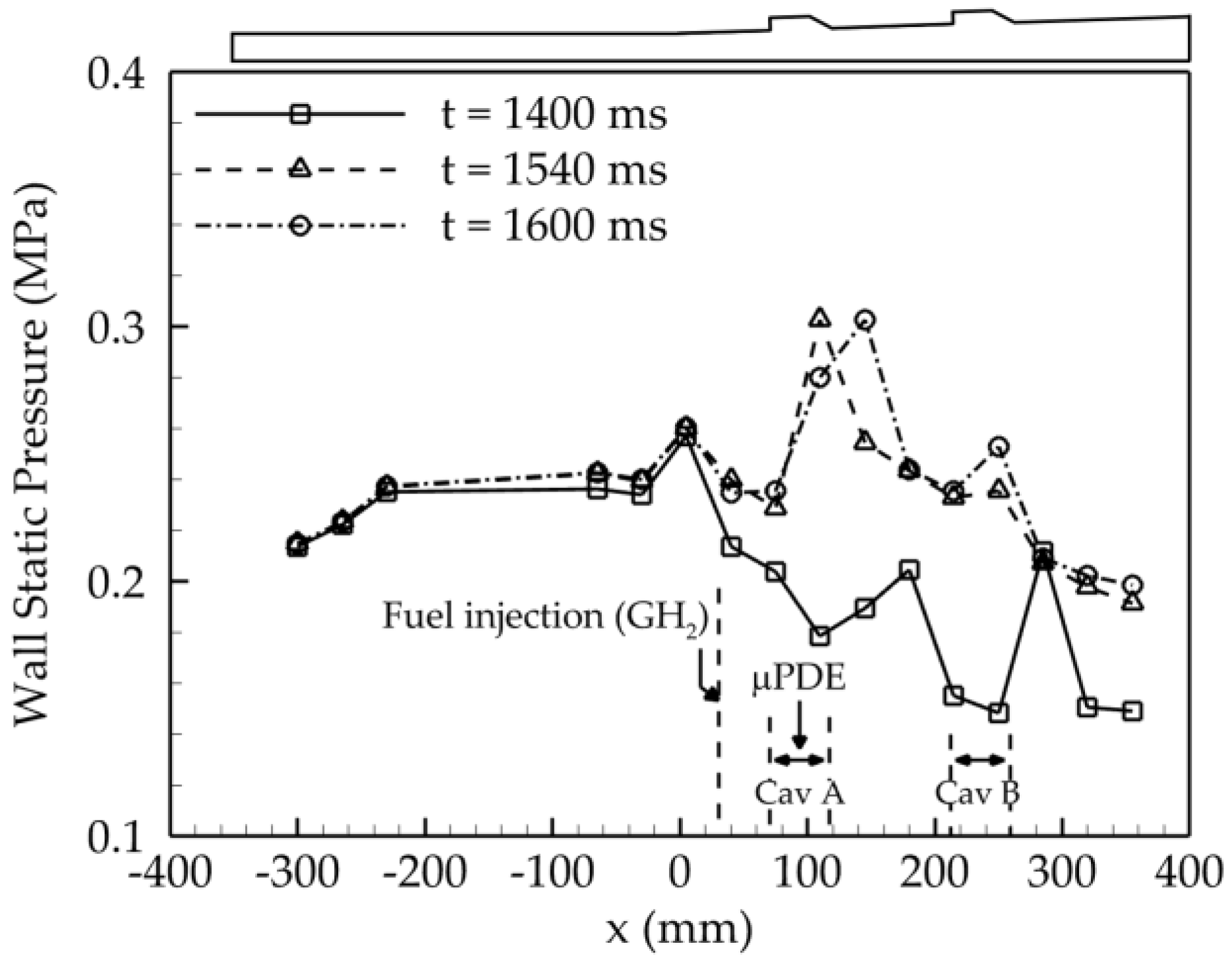
Figure 11 is the wall static pressure history of case A1 measured over time when the experiment was conducted according to the procedure shown in
Figure 10. All cases showed the same ignition process. The inlet of the isolator is located at −300 mm, and the inlet of the scramjet combustor is at 0 mm. The recording was measured at a sampling rate of 100 Hz for a total operating time of 2200 ms. At 1300 ms, fuel injection was initiated into the vitiated air mainstream, but auto-ignition did not occur. At 1400 ms, the pressure due to main flow and fuel injection was already formed in a steady state. In case A1, the peak static pressure was measured near the cavity by the propagation of the detonation wave at 1540 ms after ignition by the μPDE. After 1600 ms, the bottom wall static pressure distribution reached a steady state in all cases.
3.1. Scramjet Ignition with μPDE at Cav A
Figure 12 shows the ignition and combustion process in case A1 with Φ = 0.061. The recording condition for the corresponding Schlieren images is a sampling rate 96,000 fps, exposure time 3 μs, and acquisition resolution 1280 × 208. The numbered labels in the figure depict the ignition process. Initially, the fuel injection depth was about 0.71 mm, and oblique shock waves were induced due to the fuel jet wake in the flow of vitiated air (1). Once the flow stabilized, ignition was initiated by the μPDE (2). The detonation front produced by the μPDE was ejected from the bottom of the cavity and expanded out of the cavity, propagating upstream and downstream of the scramjet combustor (3)~(6). The detonation front took approximately 0.05 ms to reach the bottom of the scramjet combustor. The supersonic vitiated air caused the shock wave to be tilted downstream as it exited the cavity (7). The tilted shock wave reached the bottom wall before gradually reaching the leading edge of the cavity and anchoring there (8). The detonation front confined the combustion area. The oblique shock formed by the cavity leading edge was captured, and the reflected shock interacted with the boundary layer. Moreover, the combustion area decreased and became attached to the cavity leading edge (9). The subsequent labels in the figure show the combustion stabilization processes. The reflected shock interacted with the bottom boundary layer and the combustion surface (10). After the combustion front was anchored to the cavity leading edge, it was not captured between the cavity leading edge and the fuel injector. Combustion was sustained through the interaction between the cavity and the shear-layer flame (11) and (12).
Figure 13 presents Schlieren images of case A2 with Φ = 0.157, with the same recording conditions as in
Figure 12. The fuel injection depth was about 0.74 mm, inducing an oblique shock by the fuel jet wake, similar to case A1. The fuel flowing along the wall created a recirculation zone in the cavity, and a shear layer was formed between the flow inside the cavity and the scramjet combustor flow. After the ignition by μPDE, the detonation front propagated out of the cavity, and the high-temperature plume ignited the fuel. The shock wave front tilted downstream due to the main stream, and the detonation front and flame were anchored at the leading edge of Cav A, with the combustion region confined downstream of the shock wave. However, the incident oblique shock generated with the combustion front oscillated along the fuel jet wake between the fuel injector and the cavity leading edge. The induced oblique shock in the fuel injector by the fuel jet wake was reflected between the combustion surface and the bottom wall of the combustor, creating numerous oblique shock waves and a relatively distinct shock train. The combustion area created a thick boundary layer, narrowing the flow path of vitiated air. The shock train oscillated in the region between the fuel injector and the combustion surface, and when the primary shock corresponding to the incident oblique shock temporarily propagated to the fuel injector, the combustion front anchored at the leading edge of the cavity followed together. This phenomenon repeated itself, with the combustion front returning to the cavity leading edge and being maintained for a while.
Figure 14 shows the Schlieren images of case A3 with Φ = 0.282, and the recording conditions are the same as
Figure 12 and
Figure 13. The fuel injection penetrated to a depth of about 0.77 mm, increasing with injection pressure, and it induced an oblique shock by the fuel jet wake, similar to cases A1 and A2. The corresponding jet-induced shock was slightly curved by the main flow, with the fuel injection depth gradually increasing. The μPDE propagated a detonation wave out of the cavity and initiated the ignition of the scramjet combustor. Subsequently, the combustion front confined by the detonation front propagated upstream to the fuel injector, forming a jet-wake flame. However, after a certain period, the combustion front was pushed downstream to the leading edge of the cavity and anchored, leading to an unstable cavity-assisted combustion mode. The combustion area temporarily narrowed the flow path of vitiated air. Eventually, a normal shock was formed at the combustion front, which propagated upstream together with the combustion front and anchored at the fuel injector, resulting in a temporary jet wake flame mode. This oscillation between the fuel injector and the leading edge of the cavity was repeated.
Figure 15 depicts the pressure variation history along the isolator and scramjet combustor for case A1, A2, and A3. All cases showed a significant increase in wall static pressure around Cav A and Cav B. The peak static pressure due to combustion increased as Φ increased due to an increase in fuel injection pressure. In case A1 and A2, the shock train was only effective between the leading edge of the cavity and the fuel injector outlet, so the isolator wall static pressure did not increase significantly. On the other hand, the shock train in case A3 affected the upstream beyond the fuel injector outlet and the divergence section, showing a rising wall static pressure distribution in the isolator as well.
In summary, case A1 featured a cavity shear-layer flame combustion mode, while case A2 was characterized by a transient combustion mode where both the cavity shear-layer flame and the jet-wake flame were observed along a shock train. In contrast, in case A3, the shock train formed by combustion had a more widespread upstream effect, causing an unstable flame front to anchor at the leading edge of Cav A and resulting in a transient jet wake combustion mode due to shock train oscillation and normal shock propagation. Furthermore, the static pressure of the isolator drastically increased and exhibited a distribution and trend similar to the ram mode. These results were consistent with previous research by Fotia et al., who found that as Φ increased, it converted to ram mode, which was in line with the pressure distribution results of this study [
47].
3.2. Scramjet Ignition with μPDE at Cav B
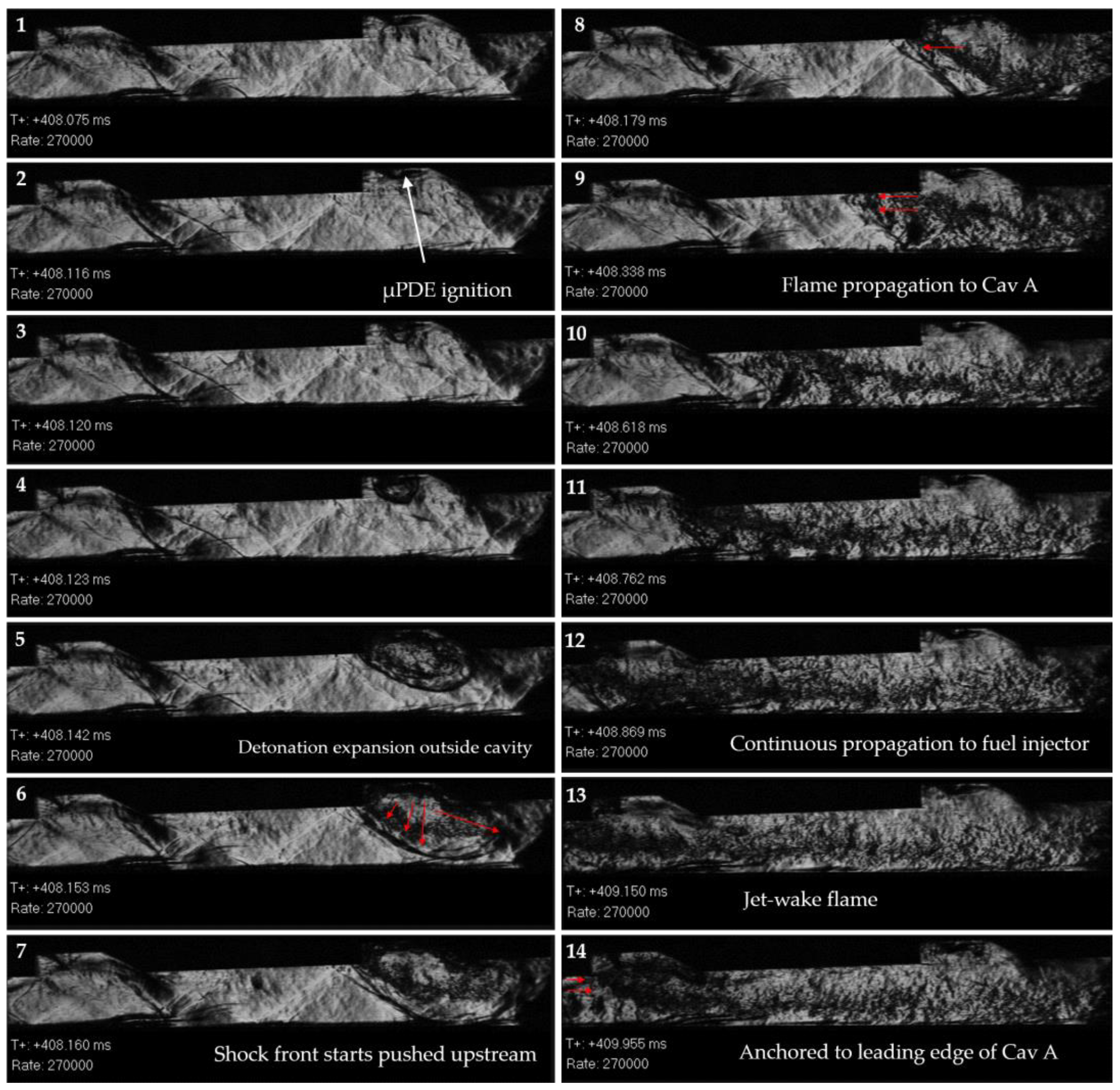
Figure 16 shows the Schlieren images of case B1 with Φ = 0.059. In the Cav B ignition experiment, the recording screen range and conditions were changed to observe all phenomena occurring in Cav A and Cav B together rather than at the exit of the fuel injector. The recording conditions correspond to a sample rate of 270,000 fps, a resolution of 640 × 112, and an exposure time of 1.0 μs. The jet-induced shock reflected and anchored at Cav B. The recirculation zone was formed inside Cav A and Cav B. The shock wave induced by the detonation propagated through the recirculation zone, followed by the high-temperature and high-pressure plume. The shock wave did not propagate upstream of Cav B and anchored at the leading edge. The combustion area propagated as the downstream shock wave exited the scramjet combustor. The shock wave did not have an impact on the upstream oblique shock. In (8)–(12) in
Figure 16, the combustion stabilization process is shown. The curved shock wave reached the downstream, and the combustion is confined within the shock wave. As the shock front was anchored at the leading edge of Cav B, the shock formed a linear oblique shock wave in front of the flame. The oblique shock reflected at the bottom wall and combustion area. The combustion was confined within the cavity shear layer and propagated downstream. The combustion did not propagate upstream, as the oblique shock wave lingered at the leading edge.
Figure 17 shows the ignition process and combustion stabilization process of case B2 with Φ = 0.156. Same as case B1, the fuel flowed into Cav B with the oblique shock corresponding to the jet-induced shock. The shock wave and high-temperature plume propagate into the cavity recirculation zone. As the shock wave came out of Cav B, the scramjet combustor was ignited. The propagation of the shock proceeded faster downstream than upstream. In addition, the shock propagated faster than the combustion area expansion. The upstream shock front was anchored at the leading edge of Cav B. The combustion area propagated downstream as the downstream shock wave exited the scramjet combustor. The shock wave reached the bottom wall of the scramjet combustor. The shock induced by the leading edge of Cav B started to curve. The curved shock wave propagated upstream of Cav B, followed by the combustion area inside the linear oblique shock attached at the upper wall. The curved shock rapidly propagated to the trailing edge of Cav A within approximately 1.5 ms. The oblique shocks were formed downstream of the curved shock and reflected under the combustion area. The flame caught up with the preceding curved shock, expanding the combustion area. The shock train formed under the Cav A combustion area. The flame was anchored at the leading edge of Cav A. Under Cav B, flames covered the scramjet combustor in a longitudinal direction. Afterwards, combustion in Cav A showed a similar trend to case A2. As in A2, the state in which the flame was anchored at the leading edge of Cav A was dominant, but the flame propagated intermittently between the outlet of the fuel injector and the leading edge of the cavity, and a jet-wake flame was temporarily seen.
Figure 18 shows the case B3 with Φ = 0.285. The fuel recirculated inside Cav B, and due to the ramp angle, the fuel exited the cavity in a vortex. The high-temperature and high-pressure shock wave and plume exited the μPDE ignitor. The shock wave propagated faster than the combustion area. As the shock wave reached the bottom wall of the scramjet combustor, the downstream shock wave expanded towards the scramjet combustor exit. The upstream shock reached the leading edge of Cav B, and the oblique shock was formed, confining the combustion area downstream. The oblique shock propagated upstream of Cav B. The flame front was attached to the oblique shock wave as an instantaneous shear layer flame. The combustion area reached the trailing edge of Cav A within approximately 0.6 ms, as shown in (8)–(11). The flame propagated over the leading edge of Cav A, creating a jet-wake flame mode transition. Afterward, combustion in Cav A showed a similar trend to case A3.
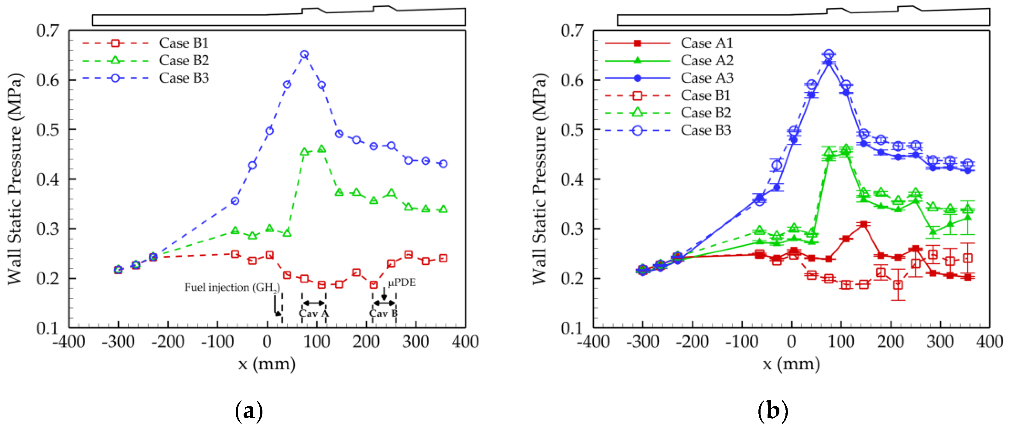
Figure 19 shows the wall static pressure history of the Cav B ignition experiment. In addition, the ignition test results of Cav A and Cav B were compared. For repeatability, all experimental cases were performed three times each. As a result of all pressure histories according to the equivalence ratio Φ, the error range is 0.02~3%. In case B1, the flame did not attach at Cav A. Therefore, the pressure did not show significant variation at Cav A. In addition, the Cav B pressure did not rise compared to the Cav A ignition of case A1. In case B2, when compared to case A2, regardless of whether ignition started in Cav A or Cav B, a similar tendency was shown when the static pressure distribution on the wall due to combustion reached a steady state. This is because the combustion phenomena observed in Cav A were similar, as shown in
Figure 13 and
Figure 17. However, as shown in
Figure 19b, the static pressure distribution at Cav B was slightly different. In case B2, the static pressure distribution due to combustion in Cav B was higher than in case A2. This is evidence of further improvement in performance measures such as combustion efficiency due to the influence of Cav B downstream of the scramjet combustor.
The wall static pressure distribution of case B3 was almost the same as that of case A3. This is related to the results observed through the high-speed Schlieren images. In the instance that B3 ignited in Cav B, there was no particular difference, as shown in
Figure 14 and
Figure 18, except for the propagation of the flame front from Cav B to Cav A, as shown in
Figure 18.
The results of the tandem cavity are summarized as follows:
- (1)
Pi = 0.74 MPa, Φ = 0.06
Combustion proceeded as it was ignited in the cavity forcibly ignited by the μPDE.
A cavity shear-layer flame was formed, and when ignited in the secondary cavity, the combustion area did not propagate or expand to the primary cavity, as shown in
Figure 20.
The combustion area was maintained, as shown in
Figure 20.
The location of the peak static pressure and the pressure distribution of the combustor were different as the front of the combustion area was located differently in the primary cavity or secondary cavity.
- (2)
Pi = 1.53 MPa, Φ = 0.16
A cavity shear-layer flame was formed immediately after ignition by the μPDE.
Due to the interaction between the combustion region and the boundary layer, a shock train of a different type from that in
Figure 20 occurred, as shown in
Figure 21.
The shock train was oscillated between the fuel injector outlet and the leading edge of the cavity, the fuel propagated along the upper wall of the combustion area, and a transient jet-wake flame was observed. However, the cavity shear-layer flame was dominant.
Even if ignited in the secondary cavity, the flame propagated to the primary cavity, and the combustion area was expanded.
When igniting in the secondary cavity, unlike when igniting in the primary cavity, there was no place where the static pressure dropped drastically, even when downstream of the combustor. This is evidence of additional performance improvement downstream due to the effect of the secondary cavity.
- (3)
Pi = 2.53 MPa, Φ = 0.28
Immediately after ignition by the μPDE, a jet-wake flame was formed, as shown in
Figure 22.
When ignited in the secondary cavity, the rate of propagation to the primary cavity became faster as the equivalence ratio increased.
The jet-wake flame could not be maintained, and the phenomenon of anchoring the combustion front to the leading edge of the cavity was repeated.
Due to the continuous cavity assistant, the combustion area filled the combustor instantaneously, forming a normal shock and propagating upstream.
The combustion front propagated along the normal shock to the fuel injector outlet.
The shock train generated by the interaction between the combustion region and the boundary layer oscillated and extended to the isolator region.
The wall pressure profile showed a tendency to change like that of the ram combustion mode.
4. Conclusions
In this experimental study, a tandem cavity-based scramjet combustor was experimentally investigated at an off-design point using Schlieren images and wall pressure profiles. The focus is on the inflow of the off-design point corresponding to the low enthalpy condition, the ignition position using the μPDE, and the effect of the equivalence ratio. As a result, the ignition mechanism by the μPDE was identified. In addition, the combustion behavior in the tandem cavity-based scramjet combustor was confirmed by forcibly igniting the scramjet combustor under inflow conditions where initiation is difficult.
For equivalence ratios as low as 0.06, cavity shear layer combustion was always seen regardless of the position of the ignitor. However, when ignited in the secondary cavity, the combustion area did not expand to the primary cavity and showed the lowest peak pressure. In the case where the equivalence ratio was 0.16, the combustion area included both the primary and secondary cavities. Regardless of the igniting position, cavity shear-layer combustion was predominantly formed, and the flame front intermittently propagated to the region between the primary cavity and the fuel injector. The region appeared to be a critical region representing a transition between cavity shear-layer combustion and jet-wake combustion. Even when the equivalence ratio was 0.28, ignition in the secondary cavity propagated the combustion region to the primary cavity. However, the propagation proceeded more rapidly. Additionally, the flame front propagated to the fuel injector exit, and jet-wake combustion was formed. The jet-wake combustion did not proceed steadily, and the flame front and shock train oscillated between the fuel injector and the cavity, and the jet-wake combustion and cavity assistant flame were repeatedly observed.
As mentioned above, the experimental results obtained through this study are test results in off-design condition. However, it was possible to present various combustion characteristics that can be shown in scramjet combustor. Although there may be obvious differences from the results at the design point to be presented in the future, it is expected to be an important reference for comparison between the results according to the inflow composition and for a more detailed review of the facility.


