Article

Integrated Conceptual Design and Parametric Control Assessment for a Hybrid Mobility Lunar Hopper

by
Jasmine Rimani
1,*,
Giordana Bucchioni
2,
Andrea Dan Ryals
2,
Nicole Viola
1 and
Stéphanie Lizy-Destrez
3
1
Department of Mechanical and Aerospace Engineering, Politecnico di Torino, Corso Duca degli Abruzzi 24, 10129 Turin, Italy
2
Department of Information Engineering, Via Caruso 16, 56017 Pisa, Italy
3
Department of Aerospace Vehicles Design and Control, ISAE-SUPAERO, 10 Av. Edouard Belin, 31400 Toulouse, France
*
Author to whom correspondence should be addressed.
Aerospace 2023, 10(8), 669; https://doi.org/10.3390/aerospace10080669
Submission received: 30 April 2023 / Revised: 16 July 2023 / Accepted: 20 July 2023 / Published: 27 July 2023
(This article belongs to the Special Issue Space Robotics and Mechatronics)

Abstract

:
The lunar lava tubes are envisioned as possible hosting structures for a human base in the Moon’s equatorial regions, providing shelter from radiations, micrometeoroids, and temperature excursion. A first robotic mission is set to scout the habitability of these underground architectures in the near future. The communication inside these underground tunnels is heavily constrained; hence, the scouting system should rely on a high degree of autonomy. At the same time, the exploration system may encounter different types of terrain, requiring an adaptable mobility subsystem able to travel fast on basaltic terrain while avoiding considerable obstacles. This paper presents a cave explorer’s mission study and preliminary sizing targeting the lunar lava tubes. The study proposes using a hybrid mobility system with wheels and thrusters to navigate smoothly inside the lava tubes. The peculiar mobility system of the cave explorer requires an accurate study of the adaptability of its control capabilities with the change of mass for a given set of sensors and actuators. The combination of conceptual design techniques and control assessment gives the engineer a clear indication of the feasible design box for the studied system during the initial formulation phases of a mission. This first part of the study focuses on framing the stakeholders’ needs and identifying the required capabilities of the cave explorer. Furthermore, the study focuses on assessing a design box in terms of mass and power consumption for the cave explorer. Following different mission-level assessments, a more detailed design of the cave explorer is discussed, providing an initial design in terms of mass and power consumption. Finally, the objective shifts toward studying the performances of the guidance, navigation, and control (GNC) algorithms varying the mass of the cave explorer. The GNC significantly impacts the design box of the surface planetary system. Hence, investigating its limitations can indicate the feasibility of mass growth to accommodate, for example, more payload.

1. Introduction

The conceptual and preliminary design of systems exploring underground planetary caves brings different challenges, mainly related to autonomy and mobility subsystem capabilities. Autonomy impacts the overall operability of the system and how the human operators interact with it, as detailed in Ref. [1]. At the same time, the mobility subsystem characteristics define the amount of space the system can cover and its capacity to avoid or overcome obstacles [2,3].
The level of autonomy is usually defined during the pre-formulation and formulation phases [4] through the concept of operations (ConOps) analysis. ConOps has established itself as the analysis to help design autonomous systems during conceptual design, as highlighted in Refs. [5,6]. The ECSS (European Cooperation for Space Standardization) standard defines four levels of autonomy on a scale from E1 (real-time control) to E4 (goal-oriented operations) [1]. The mission toward the lava tubes should be highly autonomous, requiring at least level E3 (adaptive mission operations onboard). It is not rare that a system is designed to operate under different levels of autonomy, as analyzed in Refs. [7,8,9]. In this investigation, the overall mission design study is model-based. Hence, use-case diagrams are used to visualize the mission objectives and the system’s operational capabilities.
Beyond defining the mission concept and a feasible design box, the study investigates the impact of the guidance, navigation, and control (GNC) algorithm and hardware on the design box. As the system matures after the initial conceptual study [4] (main interest of this study), it is crucial to know the boundaries of its design so that possible growth in mass can be easily accommodated. The preliminary system mass, estimated with parametric formulas, is iterated during the following design phases to accommodate the effective mission payload and equipment. The objective is to avoid costly and time-consuming system redesigns from scratch while rapidly understanding how the introduced changes will impact its performance. In the study case of this paper, the studied cave explorer is a hopper with a hybrid mobility subsystem joining wheels and a thruster. Beyond the payload, the mobility subsystem provides most of the constraints to the analyzed design. During the semi-ballistic hop, the navigation sensors and control actuators allow the system to follow a pre-designed optimal trajectory (previously studied in Ref. [10]). This hardware set limits the system’s growth capacity in terms of mass.
Hence, this paper presents a method to estimate hardware-imposed limitations during the formulation phases through an adaptable control algorithm. The algorithm allows the evaluation of the controller’s performance due to variations in the design parameters. The paper proposes a typical control scheme to guide the hopper on the nominal optimal trajectory based on PID logic. At the same time, the adaptive control varies the gains of the PID to compensate for the changes in mass and inertia due to the varying parameters. As previously hinted, an advantage of integrating GNC assessment and initial design phases is characterizing the payload size and weight limits. Moreover, a straightforward GNC loop provides an immediate perception of the feasibility of the maneuver with the selected sensor/actuator suit. It provides an invaluable aid in the sensors’ sizing and the vehicle’s actuation.
The target environment for the designed mission is the one inside a lunar lava tube. Subsurface cavities and lava tunnels could be invaluable for scientific and exploration purposes. They represent opportunistic study targets for planetology, geology, and climatology, allowing observation of the lunar materials undisturbed by external sources such as solar wind deposits and meteorites [11]. Moreover, they can double as bases for human exploration missions, sheltering the astronauts from radiations [12], micrometeoroids, high-temperature excursions [13], and regolith dust [14,15,16]. Appendix A provides an in-depth overview of the lunar lava tubes’ identification and peculiarities.
This paper contributes to the state of the art of planetary surface system design as follows:
  • presenting the conceptual design of a cave explorer with a hybrid mobility system (including a trade-off on different types of mobility) targeting the lunar lava tubes;
  • investigating in depth the performance of the Guidance, Navigation, and Control (GNC) design on the overall design box for the cave explorer.
After this brief introduction to the scope of this research, the remainder of the paper is structured as follows: Section 2 provides an overview of different studied mission concepts targeting the lunar lava tubes and the employability of adaptive control in hopping robots; Section 3 briefly presents the systems engineering methodology and the control algorithm employed in this paper; Section 4 presents the results of this study; Section 5 summarizes the main outcomes of the study, its possible extensions, and its employability on other types of systems.

2. Related Studies

2.1. Lunar Lava Tubes Exploration: Proposed Studies

Mission concepts developed for the exploration of lava tubes aim to access these underground tunnels through skylights. The skylight is a collapsed part of the tunnel ceiling, the only access to a tube located many meters below the lunar surface [3,17]. The lava tube’s floor below the skylight may present an uneven terrain because of the collapsed ceiling, while inside the lava tubes, the basaltic terrain should be pretty flat [3]. The robots that journey within the lava tubes should explore autonomously with little or no communication link with Earth, employing different mobility solutions. For example, the robotic systems may need to leap, fly, or rappel into voids [3]. The distance that must be traveled inside the lava tubes to observe a significantly different environment from a scientific standpoint is highly dependent on the morphology of the tunnel. However, based on the analysis of Ref. [3], it may be sufficient to get beyond the twilight zone, which is the transition between areas that are illuminated for some period of the day as the sun transits overhead and areas of constant darkness. This region is believed to already present interesting variations inside the tube in terms of potential to support life, volatile contents, and geological features [3]. On the other hand, Ref. [18] wishes to explore further inside the lava tubes, having as its objective to venture inside the tunnel for up to 200 m. The analyses by Refs. [19,20] state that a tunnel buried 50 m under the lunar surface should remain stable up to around 3.5 km. Therefore, venturing deeper into the lava tubes should not pose safety constraints regarding possible rock falls while exploring.
In Ref. [3], the NASA Innovative Advanced Concept Team (NIAC) proposed different mission concepts for lava tube exploration, covering a broad spectrum of possibilities. The most promising mission concept employs different systems: (i) A propulsive lander, (ii) three Cavehoppers robots, and (iii) a Livewire robot. The lander flies over the skylight during descent, scanning the terrain with LiDAR and capturing reconnaissance imagery. It then deploys three Cavehoppers, a hybrid rover able to leap into the lava tubes thanks to its piston-powered hopping actuators [3]. Another robot, Livewire, is deployed and makes a tethered descent into the skylight. Livewire brings a direct connection to the lander’s communication system, the capability to beam power, and camera and LiDAR sensors to provide reconnaissance and track Cavehopper robots during their exploration [3]. Similarly, ESA (European Space Agency) launched a campaign for innovative proposals regarding planetary cave exploration [21]. The study results of this ESA campaign can be found in Ref. [18]. The core mission concept proposed by ESA leverages the Daedalus [22], a spherical robot. The robotic sphere uses a rolling system to move in the lunar lava tubes, and it is lowered into the lava tube skylight by a mechanical crane called the Robocrane [23]. The Robocrane provides beam power and a communication relay for the cave-exploring robots. Instead, the University of Arizona suggests a lower-cost mission focusing on spherical thrust-hoppers [24,25,26]. The small spherical robots (3 kg per 30 cm of diameter) have the ability to both roll and perform small thrust-powered flights. A similar mission concept is proposed by Ref. [27], advocating using a massive team of expendable robots to explore subsurface voids. These robots are self-contained spherical jumping robots weighing around 100 g and with a diameter of about 100 mm. The reasoning behind this development is that typical planetary wheeled rovers are not well adapted to handle extremely difficult terrain or access highly sloping surfaces. At the skylight, where the ceiling collapsed, the exploration system is expected to meet rough terrain [27]. Furthermore, rovers are usually expensive, and the risk of leaving them trapped in a lunar lava tube is too high. Therefore, Ref. [27] propose low-cost and expendable systems for the first mission that ventures inside the lava tubes. Other studies explored small expendable and low-cost exploration systems, like Ref. [28] with a spring-propelled spherical robot with a total mass of 1 kg and 750 g of available weight for science instruments.
As the scientific community prepares to explore tunnels and caves on other celestial bodies, it is interesting to research different technological solutions. This article focuses on understanding the feasibility of a hybrid mobility system that combines wheels and propulsive hopping for a cave explorer. The study defines a cave explorer’s preliminary mass budget and dimensions similarly to Refs. [3,18]. Beyond this standard analysis of the conceptual design of new systems, this study provides a design box based on the envisioned GNC capabilities: How much more weight or volume can we allocate to the system without making substantial changes to its GNC subsystem?

2.2. Adaptive Control for Hopping Robots

This work proposes an adaptive control to face the parametric uncertainties introduced by changing the design parameters. In the context of control theory, are all those uncertainties introduced by unknown model parameters that may vary within a range, such as mass, inertia, dimensions, etc. … [29]. For this reason, the variation of the robot’s mass and inertia, which is considered in this case, can be modeled as parametric uncertainty under the control perspective. The system adapts the gains of the PID control scheme, designed for the nominal case, to regain all or most of its nominal performance.
In the literature, many studies address the control of hopping robots. Most of them apply a robust controller to jumping robots [30], using the technique of Sliding Mode Control (SMC). For example, in Ref. [31], a hopping robot is controlled through an SMC controller. Instead, in Ref. [32], the SMC is compared with the State Dependent Riccati Equations (SDRE) controller, which is individuated as a possible fuel-optimal robust controller for jumping robots. Other investigations propose non-robust control approaches, such as in Refs. [33,34], assuming a fixed design of the system under study with a well-known robot structure.
Unfortunately, this is not a hypothesis in this context since the system engineers are interested in the impact of the control while heavily varying the design parameters. In this context, the authors propose adopting a PID, one of the most diffused control approaches in aerospace applications, according to the literature [35]. The PID gains are evaluated using adaptive controllers, which have a great response to changes in their design parameters. Therefore, beyond being adaptable to the design, they avoid reformulating, designing, and tuning the overall hopping controller.
In the literature, some examples can be found of the application of adaptive controllers to hopping robots. Most of them are applied to legged robots [36,37] and, to the best of the authors’ knowledge, none of them is based on the Model-Reference Adaptive Control (MRAC) adaptive control technique, which is the one proposed in this paper [38]. The MRAC adaptive control technique is normally used to control helicopters [39], quadcopters [40], or surface robots [41]. The advantage of the MRAC controller lies in its capability to be put in parallel with a PID, which can be easily certified for flying platforms [5].

3. Methods and Materials

3.1. An MBSE Approach to Mission Design

The mission design methodology adopted in this paper follows the guidelines of the model-based approach of Refs. [42,43]. The approach is highly oriented toward both functional analysis [42,44,45], and scenario-based assessments [46,47]. A functional approach is the most appropriate to analyze different physical architectures that may answer the mission requirements [44]. It gives the designer the freedom to come up with innovative aerospace products without being constrained by a particular heritage. However, it also requires some simulation tools to back up the choices made during the analysis. For example, Ref. [42] proposes a study based on the house of quality as an aid to the trade-off analysis at the mission level. This section will briefly discuss the main steps of the adopted methodology. Figure 1 provides a graphical overview of the methodology.
The methodology laid out by Refs. [42,43] can be divided into seven macro-steps:
  • Analysis of the operative environment and the stakeholders’ needs.
  • Definition of mission statement, objectives, requirements, and constraints.
  • Definition of the system requirements.
  • A breakdown of the functions and operations of the system through ConOps and functional analysis.
  • An initial estimation of mass and power required.
  • An initial trade-off on the analyzed mission, system, subsystem, hardware, and software.
  • A definition of the baseline design that can then be further optimized by employing different techniques during the following design phases.
The process is both iterative and recursive [48]. The design process is iterative to detect and correct possible discrepancies or other variations from the mission objectives or the stakeholder’s needs [44]. On the other hand, it is a recursive process that adds value through the repeated application of a design process at different levels: mission architecture, system, subsystems, equipment, and components.
The first step of the methodology is to gather the stakeholders’ expectations and needs while analyzing the operative environment of the mission. This initial analysis defines the mission statement, objectives, and possible constraints. They should not be iterated on, and they will guide the design. The first mission and system requirements are directly derived from the mission objectives and stakeholders’ needs. Requirements should be iterated during the formulation phases of the design following the results of Functional analysis, ConOps, system sizing, and the trade-offs. The functional analysis encompasses different steps studied to provide a detailed functional architecture of the analyzed product [44,46]. The steps can also be considered stand-alone analyses:
  • The functional tree represents a product through the functional view. It allows decomposing operational capabilities into the basic functionalities to be accomplished by the studied system [44].
  • Following the functional tree, the allocation matrix is used to map functions to physical components. It can be built simply by matching the bottom of the functional tree, consisting of all basic functions, with rows of components able to perform those functions [44].
  • Starting from the allocation matrix, the identified physical elements are grouped into subsystems, systems, and segments following a bottom-up approach.
  • After identifying the mission’s or system’s physical elements, a connection matrix matches interacting hardware elements. The objective is to identify the connection between the different physical elements and to focus on optimizing and minimizing them. Fewer interfaces usually equal less complexity in the system.
  • Finally, a block diagram represents the physical elements’ connections, showing the type (power, mechanical, thermal …) and their directionality.
On the other hand, ConOps is used to define the mission architecture and provide a first overview of the system operations plan [4,49]. The ConOps include evaluations of mission phases, operation timelines, operational scenarios, end-to-end communications strategy, command and data architecture, operational facilities, integrated logistic support, and critical events [46]. The operational scenarios are described through the operational capabilities, defined as use cases, functions, activities, or actions the system needs to perform or maintain to operate correctly. Those functions are then associated with hardware or software. They define which elements are engaged during the different operations and detail the modes of operation of the analyzed system. A simple way to visualize the most critical elements of a ConOps is a design reference mission (DRM) diagram. The DRM provides an overview of the mission phases and the interactions between the different systems in the mission architecture. Finally, trade-off analysis employs a set of figures of merit to provide a scoring system to evaluate different solutions. The trade-off methodology employed in this paper follows the guidelines of Ref. [42]. Section 4.2 will detail the steps following its application in evaluating the cave explorer’s mobility system solutions.
Following the first requirement formulation, the first design iteration defines the system’s functional layer, physical elements, and operations. During this phase, the engineers roughly size the physical elements in terms of mass and power budget. The first sizing is usually based on mass estimating relationships, a size-up of similar systems, or a statist-based approach [48]. Different hardware elements may satisfy the designed functional architecture; hence, the systems engineers assess those budgets for different solutions. Alternately, they should know the likely impact on the system budget and the complexity of the different solutions. With the preliminary sizing inputs and the overview of the mission operations, it is possible to assess the goodness of different solutions through a trade-off. The process can be repeated until a satisfactory level of detail or solution is reached. The interrogation mark in Figure 1 signals the possibility of re-iteration or the choice of stopping at the first result of the trade-off. Usually, the design is re-iterated multiple times to refine the baseline design and detail the requirements, slowly adding value to the final solution. After a baseline is selected, the process can be recursively applied to different levels of detail (system, subsystem, or component). The result of this design process is a point design [48] that can be further optimized with other techniques such as Multidisciplinary Design Optimization (MDO).
The described conceptual design methodology stemming from Refs. [42,43] has been used to define the mission objectives and constraints, to provide a first design box for the cave explorer, and to identify the mission architecture that will enable the lava tube exploration. These higher-level results will be briefly presented and discussed before diving into the parametric design of the cave explorer.
The MBSE tool the authors used during the mission design definition is Genesys from Vitech Corporation [50].

3.2. Motion Planning and Control Design

This section describes the methods used to design the Guidance, Navigation, and Control loops. Moreover, it details how this controller may help in the design of the full system thanks to its adaptive resilience to variations of the nominal parameters (like the mass and inertia variations in this study’s specific application).
The first step for the design of the GNC loop is the definition of the involved reference frames, which are the inertial reference frame ( I = [ O , ( x , y ) ] ) and the body reference frame ( B = [ O , ( x B , y B ) ] ). In Figure 2 are reported the two reference frames and the main quantities.
For the scope of the hopping maneuver, a three-degree-of-freedom model describes the hopper dynamics. Such a model allows the guidance and control system engineer to simplify the maneuver optimization procedure and the control system design without sacrificing the results’ validity. Then the dynamics are formulated as in Equation (1).
x ˙ = V cos ( γ ) ; y ˙ = V sin ( γ ) ; V ˙ = T m 0 cos ( α ) g m sin ( γ ) ; θ = α + γ ; θ ¨ = M J Z ;
where: g m is the moon’s gravity, which is equal to 1.62 m / s 2 , T is the thrust, M is the torque due to the actuation, m 0 is the nominal mass, J Z is the nominal momentum of inertia, α is the angle of attack, γ is the flight path angle, and θ is the pitch angle (see Figure 2). The first step to designing a GNC loop is to design a desired reference trajectory, optimal in the sense of fuel consumption and feasible. For the application of this paper, the design of the reference hopping trajectory has been described and validated in Ref. [10].
In a lava tube, the hopper only has access to information about the height of obstacles. This limitation is due to the environment, as the exploring vehicle is confined within a cave and cannot gather information about the extension of obstacles from satellite images or measurements. However, the height of obstacles can be easily determined using a camera or LiDAR onboard the hopper. One possibility is for the vehicle to perform a two-step jump, where the first step measures the obstacle height and initiates a sudden hop, while in the second step, the vehicle measures, during the hop, the extension of the obstacle and calculates the required jump length. However, the authors believe a two-step maneuver would consume more fuel without ensuring the hopper safely completes the jump. Therefore, the height-only-based strategy is chosen to minimize fuel consumption, although it may lead to more failures due to shorter jumps. Moreover, the authors’ primary focus is on using a swarm of hoppers to explore the lava tube environment, where the survival of a single vehicle is considered less important than fuel efficiency.
During the wheeled phase, instead, the system acts similar to a conventional rover. Therefore, standard algorithms can be used to plan the motion, such as the A* algorithm [51]. The controller is another fundamental piece of the GNC; in this scenario, three Proportional Integral Derivative (PID) controllers are considered to control the attitude and the thrust in the nominal ideal case (nominal masses, inertia, and no sensor noises). One of the two controllers controls the attitude of the hopper with feedback from the θ , which provides feedback to the attitude control (M). The other PID instead is a PID cascade, which controls the thrust T through the feedback of the altitude of the hopper (y) and the velocity (V) in the following. These controllers are also called baseline controllers. To clarify the nominal control scheme, Figure 3 shows schematics of the control scheme.
Then, the PID controllers are flanked by adaptive controllers, which aim to mitigate the change in the nominal mass and the nominal inertia due to changes in the design of the system.
Herein is briefly presented the concept behind adaptive control in terms of transfer functions in the Laplace domain. The baseline controller transfer function K s , e is the error between a general reference signal x r and measured signal x, u b is the baseline input.
e = y r y p
u b = K s e
The adaptive loop computes the error e m between the desired response x r m , expressed in terms of the transfer function A s and the actual response of the plant. The error e m is then used to compute the adaptive estimate σ through the adaptive law in Equation (6). The Equation (7) is finally used to compute the adaptive input u a .
y r m = A s y r
e m = y p y r m
σ ˙ = ρ e m
u a = σ u b
The selector S is used to choose between feeding the augmented or baseline input to the plant when adaptive control needs to be introduced in the control scheme. The presence of the selector is a typical characteristic of the proposed control approach, and it allows the deactivation of the adaptive control in cases of necessity. The presented framework for the augmented control architecture scheme is displayed in Figure 4.

4. Results and Discussion

4.1. The Lava Tubes Mission Design

The analysis of the related work presented in Section 2.1 suggests a trend toward employing small, expendable, and highly autonomous elements inside the lava tubes. The aim is to create a simple mission to provide the first cartography of the lava tubes. Moreover, the mission should assess radiation levels and temperature excursions in the skylights, twilight zone, and underground tubes. The mission would then lay the basis for following and more complex missions, providing in-depth knowledge about the lava tube configuration, geology, and sustainability for a human base. Based on this reasoning and the previously analyzed state of the art, the mission statement has been defined as:
A robotic exploration mission is envisioned to map the zones in the proximity of the skylight, identify the potential of scientific targets to be further investigated, and assess the feasibility and safety of human presence inside lunar lava tubes.
The system would probably provide a series of images to be reconstructed on Earth while mapping the lava tubes. This analysis would help scientists understand the appearances and peculiarities of the lava tubes. In addition, it would provide the users with valuable data for assessing the overall stability of those underground tunnels. Moreover, indicating the radiation level and temperature inside the skylight and the lava tubes would provide information to prepare a human sortie mission inside the lava tubes as envisioned in Ref. [3].
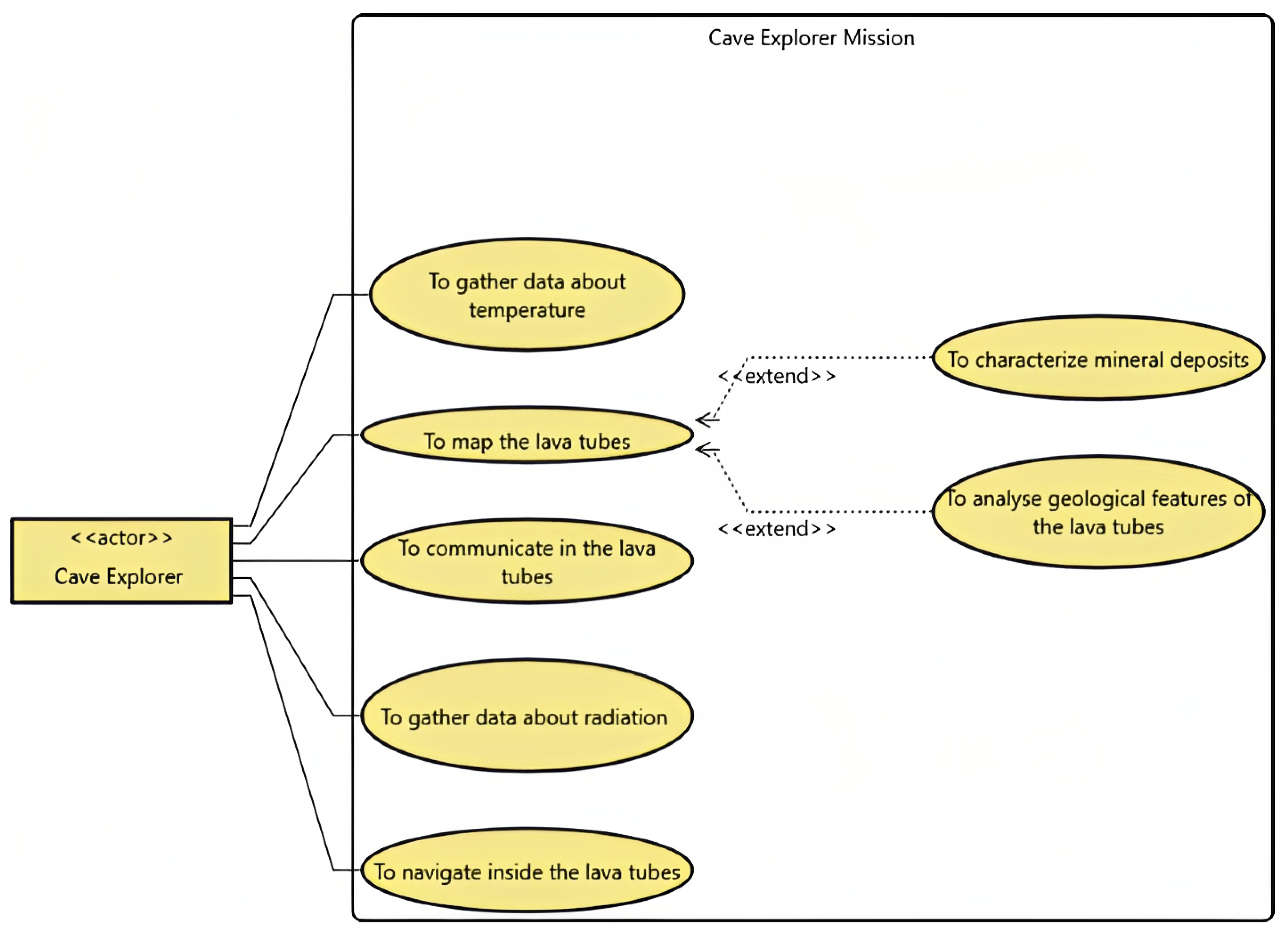
Beyond the pure scientific targets, the lava tubes’ exploration mission can be seen as a test bed for new technologies linked to mobility systems and autonomy architecture. Although there is no need for the exploration system to decide its goals, such as a level E4 autonomy. It needs to navigate autonomously inside the tube at a given depth. Hence, a level E3 with high-level goals provided by spacecraft operators on Earth, may suffice. However, a relay system from the surface will be necessary to deliver the signal to the underground tunnels. The addressed reasoning is the basis for the mission objectives formulation shown in Figure 5.
A use case diagram is the viewpoint used to visualize them:
  • In Figure 5, the use cases are the mission objectives. The primary mission objectives are directly linked to the actors, while the secondary mission objectives are linked to the primary ones with an include or extend branch.
  • The subject is the entity that performs the use cases [52]. The subject is generically addressed as a system of systems for the lava tube mission.
Use cases are usually phrased as a verb followed by a name. However, that definition has been relaxed in Ref. [42], where use cases were used to frame mission objectives. Hence, following the same methodology, the use case phrasing contains more information than just the atomic form of the verb and noun. The mission objectives are defined as use cases in the MBSE model, following the definition of Ref. [52]: a use case is a service, a behavior, that your system will perform. The aim is to include not only the mission requirements in the MBSE model but also the traceability of the mission objectives [42]. The mission statement and objectives are the driving entities for the overall design. When the mission objectives are included in the model, it is possible to visualize the direct link between mission objectives and stakeholders, highlighting which mission objective answers which of the stakeholders’ needs. In addition, the analysis in Ref. [42] links the use cases to a prioritization score that would be useful during the trade-off analysis to vote on the best mission architecture based on the required functionalities and operational capabilities. Hence, not only the use cases but also their related attributes are considered in the MBSE model. The use of include branches in use cases to capture primary and secondary requirements has been formulated in Ref. [42]. On the other hand, the extend branch is used to write down mission objectives that may be of interest but are not directly enforced by the stakeholders. An extend relationship represents an optional use case that may be enforced only if some criteria are met [52].
The selected actors in the use case in Figure 5 are the identified stakeholders with a direct interest in the mission: (i) the scientific community, (ii) space agencies. The stakeholders’ analysis is quite general. However, the lava tubes’ exploration does not look to be part of commercial-related efforts yet. Even if some of the research centres that participated in Ref. [18] are partners with some companies, the overall mission looks more toward the scientific community’s interest than the one of the aerospace industry. Leveraging the MBSE model, all the possible mission objectives can be formulated as use cases. If some of them do not make the cut to the selected baseline mission, a comment can be included to explain the rationale for the choice in the MBSE model. The initially discarded use cases can be a helpful starting point to extend the analysed mission in future iterations or versions.
From a scientific point of view, it would be interesting to venture up to 200/250 m [18] inside the lava tubes to verify the models and conclusions of studies such as Refs. [19,53]. The studies in Refs. [25,54] estimate that a small exploration system can communicate for a range of up to 80 m with a communication duration equal to 20 min for each communication relay. Therefore, the exploration system can do multiple rounds of trips to explore inside the lava tube and return to the skylight for communication purposes at given time intervals. Alternatively, a chain of relay systems can be used to hop the message back toward the skylight. The analysis of Ref. [54] is quite insightful on the set of possible architectures for swarm exploration. However, for fast prototyping of an exploration system, it is always good to look at the worst-case scenario where the system cannot recharge if not in the skylight and has to complete a round trip of 500 m in the dark of the tunnels. This evaluation can rely on the first-order approximation developed in Ref. [2]. Following Ref. [2], the exploration energy needed by a rover-like system can be expressed as in Equation (8).
E t o t a l = C r r · m · g · d η + d v · D · P
where:
  • C r r is the soil resistance, and it is usually set at 0.15 for a first rapid assessment [2].
  • η represents how much energy is used for mobility. In Ref. [2], a value of 30% is suggested.
  • m is the mass of the rover.
  • d is the traversed distance.
  • g is the celestial body gravity.
  • v is the rover velocity.
  • D is the guidance duty cycle. It represents how much time the system spends driving versus the time spent on robotic operations.
  • P is the total power available to the system.
The first part of Equation (8) defines how much mechanical energy the system employs to move on flat terrain. As the wheeled mobility system will be used to move on basaltic terrain, this metric should approximate its expected performance well. On the other hand, the second part of Equation (8) refers to the energy employed for the payload and to plan the mission. Leveraging the formulation in Equation (8), it is possible to relate the distance to be traveled with the battery mass and the power consumption of a system. The battery mass of the systems discussed in Section 2.1 sized for a similar mission ranges from 12% of the baseline configuration in Ref. [26] up to 16% of the total system mass in Ref. [22]. Imposing 16% as the upper limit of battery mass over total system mass, it is possible to estimate the expected system mass for a given amount of consumed power, the distance covered, and the driving duty cycle, as shown in Figure 6. The assessment would not be precise. However, it can provide the order of magnitude expected for a lava tube explorer. Most of the duty cycle points are layered on top of each other. The graphs in Figure 6 highlight with colors the minimum duty cycle that can be sustained for a given configuration in terms of system mass, battery mass, and power consumption for a given distance to be covered.
In the estimation of Figure 6, the exploration system velocity is assumed to be 0.10 m/s. In comparison with other planetary rovers, this velocity is quite elevated. For example, the Yutu rover had a velocity of around 5.5 cm/s [55], and Curiosity had a similar maximum velocity of 5 cm/s [55], while Spirit and Opportunity were moving at 1 cm/s [55]. However, new micro-rovers and small robotic systems trend toward incrementing this velocity up to 0.25 m/s. On the other hand, the power consumption varies from the 20 W of the SphereX [26] to the 300 W of the Daedalus [22]. The duty cycle indicates the proportion of the traverse time that the rover effectively drives against the percentage of time used for payload operations or navigation and guidance assessments [2]. Hence, a higher duty cycle indicates a system that spends more energy on driving than on planning or using its payload, covering more distance with less battery consumption. The primary assumption of the model in Equation (8) is that the non-driving energy (plan computation, path estimation, sensor fusion, localization, data collection …) accounts for far more energy than simply driving from point to point. The effective energy required for mobility depends on rover mass, distance covered, and terrain type. On the other hand, the energy for sensing, computing, and communicating depends on the total mission time that the system is not spending driving. Moreover, some lower-level robotics functionalities (like reactive obstacle avoidance) run even when the system drives, increasing the overall robotics power consumption. Looking at the results in Figure 6, a system with a mass of 25 kg and a power consumption of 100 W should at least spend 30% of its energy driving around to cover the 500 m distance. The most likely duty cycle to be adopted during navigation would be around 40% to 60%. It depends on the number of obstacles the exploration system encounters, its task and motion planning algorithms, and the payload activities to be carried out.
Beyond the mission objectives and the estimation of likely mass and power consumption, defining the time the system should operate is essential. To not have to equip the system with heavy thermal protection, it is assumed that the maximum length of this first exploratory mission would last around one lunar day, as in Ref. [18]. All this numerical information can be included in the MBSE model and will provide high-level constraints for the cave explorer’s final design box.
Following the design process laid out in Section 3.1, the focus shifts toward defining the main mission elements and their operations, leveraging functional analysis and ConOps. Similarly to Refs. [3,21], this study identifies four elements needed to accomplish the mission:
  • A skylight explorer would: (i) relay data from the lava tubes outside, (ii) recharge the exploration systems, (iii) evaluate the temperature and radiation environment inside the skylight. It may deliver some payload inside the lava tubes as well. However, for the architecture defined in this study, the cave explorer can access the lava tubes autonomously.
  • A cave explorer would venture inside the lava tubes and gather information on the morphology and geometrical structure of the lava tubes as well as their habitability potential, as detailed in the use case in Figure 7.
  • A rover drives the other elements in the proximity of the skylight. It would probably be equipped with ground-penetrating radar to study the terrain around the lava tubes.
  • A lunar lander carries the other elements from a low lunar orbit to the surface. It can be used as a relay hub for communications.
Figure 8 and Figure 9 show the mission concept as DRM (Design Reference Mission). Figure 8 highlights the access mechanism of the cave explorer in the lava tubes. While Figure 9 highlights the use of the skylight explorer as a relay element for the mission, delivering data back to the rover through a cable [18].
After defining the overall architecture that frames the cave explorer mission, the aim of this paper is to provide an initial design of the system and its mobility capabilities.

4.2. Cave Explorer Conceptual Design and Preliminary Sizing Assessment

Following the subsystem classification of Ref. [48], the cave explorer is composed of seven subsystems ((i) structure and mechanism subsystem; (ii) mobility subsystem; (iii) power subsystem; (iv) telemetry, tracking, and command subsystem; (v) thermal subsystem; (vi) guidance, navigation, and control subsystem; (vii) command and data handling subsystem) plus the payload.
The most critical trade-off to be made during the initial definition of the cave explorer focuses on choosing its mobility subsystem. The lava tubes are formed by volcanic activity. Therefore, the terrain inside the lava tubes, past the skylight, is expected to be relatively flat with few obstacles [16]. The estimated maximum obstacle height is around 100 mm based on the analysis in Ref. [22]. For this type of environment, a wheeled or rolling system would provide the best performance on flat terrain, consuming less mobility-related power. However, in proximity to the skylight, the terrain is expected to be rough and hardly traversable with simple wheels. Moreover, there may be some areas inside the lava tubes where the ceiling has partially collapsed. Therefore, the exploration system should be able to move around or over these areas.
To overcome more significant obstacles, mechanical hopping [3] and thrust-base hopping [24,25] can be considered. However, as analyzed in Refs. [24,25], hopping bots using mechanical systems may struggle in the lava tubes. Mechanical hopping complicates asset determination for landing gently at a safe point, especially in a rugged environment. Flying allows the system to take off and land gently, minimizing impact forces. However, a flying bot would use propellant, contaminating the soil touched by the plume. To lower the contamination risk, Ref. [56] suggests the use of cold-gas-based propulsion using compressed nitrogen with a specific impulse around 60 s. Another more volume-efficient solution is electrolysis propulsion, as used in Ref. [26]. It permits the storage of H 2 and O 2 in solid form [26], saving space, and the required amount of fuel and oxidizer can be generated on demand [57]. This monopropellant has a specific impulse, I s p of around 140 s [58]. This type of propulsion can be quite volume-effective, as 7.8 kg of propellant may be stored in less than 10 L of volume, as studied in Ref. [59]. Regarding the level of Isp, Ref. [59] claims a theoretical Isp well above 300 s. A study from Ref. [60] proposes a new type of hybrid legged-wheel design with good obstacle traversability similar to legged systems and low power consumption on flat terrain such as wheeled systems. Moreover, this type of mobility subsystem should be able to climb a plateau with a height of 25 cm [60]. It may be a versatile solution to be investigated for the lava tubes’ mission. However, it does not allow the cave explorer to directly access the lava tubes without external help.
Following this reasoning, the authors performed a trade-off to define the mobility subsystem design for the cave explorer. The figures of merit (FOM) partially derive from Ref. [61]. Ref. [61] is an extensive review that compares different types of mobility based on metrics such as (i) speed, (ii) obstacle traverse capability, (iii) slope climb, (iv) soil sinkage, (v) mobility subsystem simplicity, (vi) energy consumption, (vii) payload mass, (viii) soil-mobility subsystem interaction, (ix) technological readiness level (TRL). These FOM are compared on a scale from 1 to 5 [61]. The qualitative assessments liked the different scores: (i) very low for 1, (ii) low for 2, (iii) medium for 3, (iv) high for 4, (v) very high for 5. The only FOM that reverses this equivalence is energy consumption: the more energy-efficient a system is, the higher the score will be. A similar scale is used in the trade-off presented in this article.
This research does not consider soil sinkage (related to the mobility-subsystem weight), soil-mobility subsystem interaction, or TRL as FOM because (i) the envisioned exploration system is light-weight; (ii) the system interaction metric looks at the effect of planetary soil on long-term missions; and (iii) the study is more focused on innovation than on existing technologies. Instead, this study considers the redundancy of the mobile element, the localization accuracy, the design innovation, and the mobility system’s controllability. The mobile element redundancy relates to the possibility of accomplishing the mission, even partially, due to some faults in the mobility subsystem. Wheeled rovers can function even with failures in one or two wheels, giving them a score equal to 4; hybrid mobility subsystems should be more resilient to failure, gaining a score equal to 5. On the other hand, a system with good localization accuracy and position estimation can travel faster and more efficiently inside the lava tubes. For example, given the same set of sensors, a ballistic hopper may have less precise localization (score 1) than a wheeled rover (score 3). The FOM assessing the innovation has been added as exploring new concepts for the lava tubes’ exploration is interesting. Exploring the goodness of new solutions is essential to extending the knowledge base and developing a feasible exploration system for exploring planetary caves. Therefore, more innovative solutions have a higher score for this FOM. The controllability metric pinpoints how easy or difficult it is to control a system’s dynamics based on its mobility subsystem. For example, a spring-based hopper can control its overall trajectory and landing point less than a propelled one.
The employed trade-off methodology is presented in Ref. [42], where the weights for the different figures of merit are graded considering the mission objectives and the associated stakeholder rating. Table 1 shows the scale associated with the rating.
Table 2 and Table 3 show the metrics and type of mobility system considered in the trade-off study and the grading values derived from the influence matrix in Table 1.
The metrics maximum speed capability has a null affection level: more than the speed, the battery consumption per covered distance indicates the goodness of the chosen configuration to explore the depth of the lava tubes. The best mobility configuration considering battery consumption is a simple-wheeled system. However, the configuration is lacking from the point of view of obstacle traversability, where hopping systems score better. Considering the affection level and the metrics’ grading, the trade-off results are shown in Table 4 and Table 5. The identified winning solution was a hybrid wheeled and hopping solution. The wheels would give an advantage in battery consumption on the flat basaltic terrain inside the lave tubes. At the same time, the controlled propelled hop would provide remarkable obstacle traversability capabilities on the skylight terrain. Interestingly, Ref. [62] addresses in its conclusions the exploration of possible designs of a hybrid hopping rover as an interesting outcome of its comprehensive trade-space exploration of mobility subsystems of planetary exploration systems.
The equipment of each of these subsystems would not deviate much from that of a typical micro rover similar to the one described in Ref. [63], with passive thermal protection. The command and data handling subsystem and the guidance, navigation, and control subsystem are the subsystems that mostly change when a higher level of autonomy is introduced. The command and data handling subsystem needs more computational power. It should be equipped with a secondary computation unit entirely dedicated to computing the actions to be executed for the GNC to safely move the system in the lava tubes. Moreover, the communication constraints will require providing the command and data handling subsystem with a module dedicated to FDIR (Failure Detection Identification and Recovery) to be able to react to unexpected failures without human support. The GNC subsystem is going to be affected by the choice of the mobility subsystem. As mobility is hybrid, the GNC subsystem would have a module dedicated to controlling the cave explorer’s trajectory during the propelled arcs. It will then encompass more conventional motion planning, navigation, and control of the wheels when moving as a conventional rover. Due to the required level of autonomy, the other subsystems will gain more sensors to enable autonomous decision-making by the command and data handling subsystem. Figure 10 presents an artistic view of the hopper.
The designed cave explorer weighs around 15 kg, with 2.5 kg of available payload, around 4 kg of propellant mass, and an expected power consumption of 100 W (Equation (9)) [1]. The m b a t t e r y is evaluated from the estimation of Figure 6, considering a 100 W power consumption, 40% duty cycle, and a power density of 120 Wh/kg for a Lithium-Ion Battery [64]. The system should have a velocity of 0.2–0.25 m/s and reach at least 200 m inside the lava tube. Moreover, the minimum sensor suite to identify the state of the rover during the hopping phase consists of an IMU and an altimeter. However, a stereo camera and a LIDAR are necessary to navigate during the rover phase. The propulsion system ( m p r o p u l s i o n ), without propellant, should weigh around 1 kg, of which 650 g are for the thruster. This value aligns with the specifics of different types of propulsion in Ref. [65]. It is slightly more than the mass allocated in Ref. [26], providing a bit of margin for future iterations. The m o t h e r s encompasses all the other components such as sensors, on-board computer(s), connectors, and wheels. it is worth noticing that some sensors, such as cameras, can be used both as payload and for navigation purposes, helping optimize the system’s mass and volume. The m p r o p e l l a n t is evaluated for a limit situation where the system needs to hop almost continuously to avoid obstacles, as analyzed in Ref. [10].
m t o t a l = 15 kg m p l = 2.5 kg ; m p r o p u l s i o n = 1 kg ; m b a t t e r y = 2.5 kg ; m p r o p e l l a n t = 4 kg . m o t h e r s = 5 kg . p a v g = 102 W
The mass estimation loop is an iterative process that changes the payload mass fraction until convergence, as described in Ref. [10]. Different parametric formulae are used to estimate the likely-to-be mass of the propellant or the different subsystems. The initial guesses from which the computation starts are: (i) a thrust-over-weight ratio ( T W ) equal to 1.3, (ii) a propellant Isp of 300 s similar to the design value proposed in Ref. [59] and Ref. [26], (iii) a hop distance of 3 m. From these initial guesses, a simplified formula based on the definition of the Isp as T m ˙ g 0 is used to evaluate the percentage of needed propellant per hop as shown in Equation (10).
% m p r o p = Δ m m t o t a l = T W g m o o n g 0 t f l i g h t I s p
where: (i) T W is the thrust over weight ratio, g m o o n [m/s 2 ] is the Moon gravity acceleration, g 0 [m/s 2 ] is the Earth gravity acceleration, t f l i g h t [s] is the time of the propulsed hop, Isp [s] is the propellant specific impulse. In this initial calculation, t f l i g h t is assumed to be equal to 2.4 s for the powered ascent. The full mathematical background of this evaluation can be found in Ref. [10]. After evaluating the usual percentage of mass used at each hope, it is possible to evaluate the mass of propellant as in Equation (11).
m p r o p = m t o t a l m t o t a l ( 1 % m p r o p ) D / R h o p
where: (i) m t o t a l is the total system mass iterated in the parametric design; (ii) m p r o p is the percentage of propellant mass consumed at each hop; (iii) D is the distance to be covered, set to 500 in this worst case scenario, (iv) R h o p is the hop distance. With this calculation, the propellant mass is estimated at around 3.2 kg. However, during initial assessments, it is always advisable to be conservative with the estimations, as in the case of m p r o p e l l a n t . Hence, a 20% margin is applied to this initial estimation. The objective of a more detailed design would be to engineer a more reactive system with a more balanced energy subdivision between mobility and robotic energy. An approach similar to Ref. [26] would be the next logical step to optimize the mass and dimensions of the cave explorer.
The required thrust level for 15 kg would be a minimum of 32 N. From the estimation of Ref. [26], it seems a feasible value. Effectively, in Ref. [26], the authors analyzed different configurations of the SphereX for a lunar and Martian scenario, imposing the thrust level to be two times the system weight.
A parallel with micro-rovers on Earth is used for the first estimation of the hopper’s likely dimensions. The wheel diameter is set to be 13 cm, as in Refs. [63,66]. The rocker boogie will have a height of around 20 cm (from the wheel center to the body attachment) and a width of 40 cm (between the centers of the wheels). The width is evaluated using a proportion for lunar landers. Typically, the footpads of a lunar lander are distanced from each other by around two times the lander’s body diameter. The height should allow for a minimum clearance from the ground to protect the thruster. The minimum ground clearance for a lander is evaluated as d n o z z l e 2 . In our case, it would equal 4 cm. The exposed length of the thruster will be around 9 cm. In contrast, the overall length of the thruster system is around 18 cm. The points of attachment of the thruster to the main structure should be positioned on the bulkhead of the main body chassis and should coincide with the attacks for the rocker boogie. This solution can be a good trade-off between decreasing the structural mass and distributing the mechanical loads of the structure.
The main body dimensions are preliminary assessed by looking at the volume of the rover in Ref. [66]. The hopper would include equipment with a similar volume to the rover used to test its ground mobility operations in Ref. [66]. From Ref. [59], it is estimated that an electrolysis propulsion system of 7.8 kg can be stored in less than 0.01 m 3 . Trying to be conservative with the estimation, as the design is still in its early stages, the propulsion subsystem will use around 0.01 m 3 of the internal space of the main body. The volume of the rover equipment in Ref. [66] plus the propulsion system would be around 0.03 m 3 . Starting from this value, it is possible to preliminary set the width, length, and height of the system’s main body (excluding the rocker boogie and the exposed thruster length of 9 cm) as in Equation (12). The total system height will be around 15 cm higher than the body height.
H e i g h t = 0.42 m ; W i d t h = 0.17 m ; L e n g t h = 0.42 m ;
This quick estimation will be refined during the following design phases. However, it already provides some valuable starting values for the GNC assessment.
When the hopper uses its mobility system, it acts similarly to a conventional rover. No particular innovation is introduced with respect to standard motion planning such as the one analyzed in Refs. [7,67]. However, to prove the feasibility of the design, the focus should shift toward assessing the possible hopping trajectories and the system’s control capabilities to follow them. As this is a preliminary design, it is not unlikely that the hopper’s mass will probably change and more likely increment. The following part of this study analyzes how the control capabilities hold while varying the system mass of about ± 5 kg.

4.3. Trajectory Control and Its Impact on the Design

The results of the design of the nominal controller based on the PID approach are discussed in this session, together with the nominal results of the MRAC. Following this initial assessment, the results of the adaptive controller applied to the system in the presence of varying design parameters are analyzed.
Figure 11 shows the results for a nominal case. In the nominal case, the controllers are tuned based on a small perturbation model. The attitude is controlled by a PID controller with the gains K p θ = 21.5 , K i θ = 0 and K d θ = 5.01 . The cascade PID to control the altitude and the velocity is constituted of two proportional gains K p y = 14.4 , K i y = 0 and K p V = 61.7 , which respectively weight the error on the altitude and the error on the velocity. They provide as output the necessary thrust to follow the trajectory. The gains, which are not indicated, are selected to assume a zero value.
Figure 12 shows an analysis of the performance of the adaptive controller when the design parameters are changed during the mission design process. In this figure, the results are reported when the mass can vary between m 0 5 kg and m 0 + 4.5 kg while maintaining the same thrust level for the hopper. Note that the interval of variation is not symmetrical because the performance in terms of time of flight starts to decrease when the mass is increased by about 4 kg; on the contrary, the time of flight performance of the PID starts to get worse when the mass is increased by about 3.5 kg; this implies that a different thrust solution is required in those cases. The jump height performance deteriorates already when the mass is increased only by 0.5 kg, but the MRAC controller can always jump higher by about 200 mm on average than the baseline controller. The designer can understand that they can maintain a portion of the performance without altering the control architecture, simply by increasing the PID gain with the multiplicative factor provided by the MRAC. Nevertheless, the MRAC approach can adapt the gain of the nominal PID controlled to obtain better performances in terms of jump height and time of flight in cases of variation of design parameters.
Naturally, if the thrust T is brought from 31 N up to 40 N in the nominal working conditions, the jump is possible up to a total weight of 20 kg without exceeding the nominal requirements on the Thrust/Weight ratio (see Figure 13). Thanks to the enhanced thrust capabilities, the time of flight performances remain consistent across the entire range of explored mass increments. The performance in terms of nominal height has been enhanced, and the MRAC offers a similar level of improvement as the previous thruster. There is no significant advantage if the adaptive control is put on the attitude control even in the presence of variation in the dimensions of the vehicle since the PID provides a good reference following within the working range of the selected reaction wheels.
As can be clearly seen in the results, the inclusion of control in the sizing phase contributes to making the design more effective. In fact, the adaptive control scheme is based on a classical PID control and adapts the multiplicative gain of the PID to improve the performance when the mass and the inertia are varied. The use of this control scheme (see Figure 4) also has the advantage of being based on the PID technique, which can be easily space-certified. Moreover, it provides the designed system with a quick perception of whether the actuation system can still sustain the payload and how fast the performances can decide if the mass is increased or if the dimensions are changed during the design process. For the search of completeness in Figure 14 is also reported the behavior of the PID controller on the pitch angle when the dimensions, and consequently the inertial, are varied. The PID can maintain the performances. Therefore, an adaptive controller is not necessary.

5. Conclusions and Future Works

This study analyzes the mission of an exploration system, the cave explorer, targeting the lunar lava tubes. An initial analysis of the stakeholders’ needs and interest in the mission is carried out to understand the mission drivers and what is expected of the cave explorer. An initial configuration for the cave explorer is proposed, providing a general indication of its layout, mass, dimensions, and power consumption. A trade-off analysis for system mobility is carried out, also considering the innovation factor of the explored solutions. The overall initial mission definition and size of the cave explorer follow a standard approach in systems engineering. However, it innovates in its thoughtful analysis of the system’s control capabilities during the propelled hops. This analysis aims to provide an indication of the boundaries within which the mass of the system can vary during the following design phases without losing control capabilities.
This work proposes a nominal control based on a classical approach, where a PID is put in parallel with an MRAC adaptive control. It is evident that the presence of an adaptive control already improves the working range of the PID in cases of uncertainty. It improves the performance of the whole system. Moreover, the proposed approach is suitable for in-flight certification, which makes the proposed choice even more convenient. Different control approaches based on optimization could provide better performance regarding fuel optimization. Alternatively, robust approaches could be investigated in cases where other uncertainties are expected, e.g., model uncertainties. Nevertheless, the MRAC shows the advantages of integrating the GNC into the design of the process. In fact, it shows directly the limitations of the overall system and how the performances decrease if no adaptation of the gains of the control is performed. In the future, a deeper integration process could be analyzed, where the design of the rover GNC is more flexible and adaptable, accounting for the variation of more design parameters.
The work in this paper is a case study of the coupling of design and control capability assessment to provide a feasible design box. Different designs of space systems are heavily affected by the choices of the GNC system sensors, actuators, and algorithms. However, most studies focus on optimizing the GNC and building the surrounding system, falling short of overall system optimization. This is why it is interesting to provide a design box based on the GNC with an estimation of how the performance will vary and how acceptable those variations are. These issues are partially tackled with multidisciplinary design optimization (MDO). However, this study presents itself as a precursor to the MDO’s in-depth analyses; the mission architects are still exploring different designs and solutions. The objective is to understand the design box and find a feasible design. After this initial assessment, an accurate optimization analysis can bring the system from an initial point design to a final optimized product.

Author Contributions

Conceptualization, J.R., G.B. and A.D.R.; methodology, N.V., J.R., S.L.-D. and G.B.; software, J.R., G.B. and A.D.R.; validation, J.R., G.B. and A.D.R.; formal analysis, J.R., G.B. and A.D.R.; investigation, J.R., G.B. and A.D.R.; resources, J.R., G.B. and A.D.R.; data curation, J.R., G.B. and A.D.R.; writing—original draft preparation, J.R., G.B. and A.D.R.; writing—review and editing, N.V. and S.L.-D.; supervision, N.V. and S.L.-D.; project administration, N.V. and S.L.-D.; funding acquisition, N.V. All authors have read and agreed to the published version of the manuscript.

Funding

This research received no external funding.

Data Availability Statement

Data is contained within the article.

Conflicts of Interest

The authors declare no conflict of interest.

Abbreviations

The following abbreviations are used in this manuscript:
ECSSEuropean Cooperation for Space Standardization
ESAEuropean Space Agency
FDIRFailure Detection Identification and Recovery
FOMFigures Of Merits
GNCGuidance, Navigation and Control
IMUInertial Measurement Unit
MBSEModel-based Systems Engineering
MDOmultidisciplinary design optimization
MRACModel Reference Adaptive Control
NIACNASA Innovative Advanced Concept Team
PDProportional Derivative
PIDProportional Integral Derivative
SDREState Dependent Riccati Equations
SMCSliding Mode Control

Appendix A. The Lunar Lava Tubes

The existence of caverns and planetary pits on other bodies in our solar system has been speculated since the 1960s [68,69]. These structures are most likely the result of lava tubes, which form when the surface layer of lava flowing from a volcano cools, insulating the layer beneath and allowing it to continue to flow. As a result, several meters of hardened lava divide an empty, cylindrical tube from the surface.
However, new scientific instruments onboard different spacecraft around the Moon have been decisive in providing a better understanding of the shape and the general dimensions of those underground tunnels from orbit. In recent years, the presence of subsurface voids and tunnels has been confirmed in volcanic areas of the Moon [70]. Three potential lunar lava tubes’ skylights have been detected by the missions LRO (Lunar Reconaissence Orbiter) [71] and Selene [72], two on the near side (Marius Hills, Mare Tranquillitatis) and one on the far side (Mare Ingenii), Figure A1.
Figure A1. Lava tubes (Marius Hills, left; Mare Ingenii, center; Mare Tranquillitatis, right). Image from SELENE and LRO missions (figures adapted with permission from Refs. [3,71,72]).
Aerospace 10 00669 g0a1
To understand the peculiarities of this Moon’s volcanic architectures, the geologists started creating a parallel with the Earth’s lava tubes [69]. The increased width of the lunar lava tubes has been estimated considering the Moon’s reduced gravity. A calculation from Ref. [20] estimates that lunar lava tubes 300 m wide and a height of around 100 to 150 m can be stable with a minimum roof thickness of one m. The height is estimated as 1/3 of the lava tube width. The study conducted in Ref. [19] starts from the data of SELENE [73] to estimate a likely width of the lava tubes of around 1 to 2 km. They demonstrate that those lunar lava tubes are likely stable, with a roof thickness ranging from 100 to 200 m and a height of around 300 to 500 m. Starting from the Earth parallel, Ref. [69] states that the lava tubes should have smooth floors and soda straw-like stalactites created by lava trickling from the roof. The sinuous rilles visible on the Moon’s surface nearby these lava tubes were most likely produced by lava tube collapse [16]. Those structures unravel inside the Lunar crust for several kilometers [71]. However, the near-term interest lies in the zone in the immediate proximity of the skylight [74].
The Mare Ingenii and the Mare Tranquillitatis pits have a diameter of around a hundred meters, and depths over fifty meters [74], as reported in Table A1. On the other hand, the pit in Marius Hills should have a depth of around fifty meters and a maximum diameter of around sixty meters [69,74], which may facilitate possible accesses to the lava tube, Table A1. The Marius Hills skylight was first identified by the SELENE mission [72] and later by the Lunar Reconnaissance Orbiter (LRO) [71]. In most of the analyses, the lava tube in Marius Hills is identified as the most attractive target for a first mission tasked with exploring the lunar lava tubes. From a geological point of view, the interest lies in its high concentration of iron and titanium-rich minerals [74]. From an accessibility point of view, the Marius Hills lava tube is the nearest to the lunar surface.
Table A1. Skylights discovered by Selene dimensions given in Ref. [16].
LocationLatitude, LongitudeDiameter (Min–Max)Depth (m)
Marius Hills 303 . 3 E, 14 . 2 N47–6048 ± 10
Mare Tranquillitatis 33 . 2 E, 8 . 3 N85–97100 ± 16
Mare Ingenii 166 . 0 E, 35 . 6 S66–10160 ± 15

References

  1. Gao, Y.; Burroughes, G.; Ocón, J.; Fratini, S.; Policella, N.; Donati, A. Mission operations and autonomy. Contemp. Planet. Robot. Approach Towar. Auton. Syst. 2016, 6, 321–401. [Google Scholar]
  2. Xiao, X.; Whittaker, W.L. Energy Utilization and Energetic Estimation of Achievable Range for Wheeled Mobile Robots Operating on a Single Battery Discharge; Robotics Institute: Pittsburgh, PA, USA, 2014. [Google Scholar]
  3. Whittaker, W. Technologies Enabling Exploration of Skylights, Lava Tubes and Caves; Technical Report; Astrobotic Technology Inc.: Pittsburgh, PA, USA, 2012. [Google Scholar]
  4. Hirshorn, S.R. NASA Systems Engineering Handbook Revision 2; National Aeronautics and Space Administration; NASA Headquarters: Washington, DC, USA, 2007. [Google Scholar]
  5. Damak, Y.; Leroy, Y.; Trehard, G.; Jankovic, M. Operational Context-Based Design Method of Autonomous Vehicles Logical Architectures. In Proceedings of the 2020 IEEE 15th International Conference of System of Systems Engineering (SoSE), Budapest, Hungary, 2–4 June 2020; pp. 439–444. [Google Scholar]
  6. Vassev, E.; Hinchey, M. Autonomy requirements engineering. In Autonomy Requirements Engineering for Space Missions; Springer International Publishing: Cham, Switzerland, 2014; pp. 105–172. [Google Scholar]
  7. Winter, M.; Rubio, S.; Lancaster, R.; Barclay, C.; Silva, N.; Nye, B.; Bora, L. Detailed description of the high-level autonomy functionalities developed for the ExoMars rover. In Proceedings of the 14th Symposium on Advanced Space Technologies in Robotics and Automation, Leiden, The Netherlands, 20–22 June 2017; pp. 20–22. [Google Scholar]
  8. Rabideau, G.; Benowitz, E. Prototyping an Onboard Scheduler for the Mars 2020 Rover; International Symposium on Artificial Intelligence, Robotics and Automation in Space (Online Symposium). 2020. Available online: https://www.hou.usra.edu/meetings/isairas2020fullpapers/pdf/5002.pdf (accessed on 29 April 2023).
  9. Brooks, S.; Litwin, T.; Biesiadecki, J.; Abcouwer, N.; Del Sesto, T.; McHenry, M.; Myint, S.; Twu, P.; Wai, D. Testing Mars 2020 Flight Software and Hardware in the Surface System Development Environment. In Proceedings of the 2022 IEEE Aerospace Conference (AERO), Big Sky, MT, USA, 3 May 2022; pp. 1–13. [Google Scholar]
  10. Gamboa, J.; Rimani, J.; Lizy-Destrez, S. Sizing of a Propelled-Hopping System on the Moon. In Proceedings of the 73rd International Astronautical, Paris, France, 18–22 September 2022. [Google Scholar]
  11. Haruyama, J.; Morota, T.; Kobayashi, S.; Sawai, S.; Lucey, P.G.; Shirao, M.; Nishino, M.N. Lunar holes and lava tubes as resources for lunar science and exploration. In Moon; Springer: Berlin/Heidelberg, Germany, 2012; pp. 139–163. [Google Scholar]
  12. Angelis, D.G.; Wilson, J.; Clowdsley, M.; Nealy, J.; Humes, D.; Clem, J. Lunar lava tube radiation safety analysis. J. Radiat. Res. 2002, 43, S41–S45. [Google Scholar] [CrossRef] [PubMed]
  13. Horvath, T.; Hayne, P.O.; Paige, D.A. Thermal and Illumination Environments of Lunar Pits and Caves: Models and Observations From the Diviner Lunar Radiometer Experiment. Geophys. Res. Lett. 2022, 49, e2022GL099710. [Google Scholar] [CrossRef]
  14. Wagner, R.; Robinson, M. Lunar Pit Morphology: Implications for Exploration. J. Geophys. Res. Planets 2022, 127, e2022JE007328. [Google Scholar] [CrossRef]
  15. Clementine Mission eoPortal Webpage. Available online: https://directory.eoportal.org/web/eoportal/satellite-missions/c-missions/clementine (accessed on 15 June 2012).
  16. Ashley, J.; Boyd, A.; Hiesinger, H.; Robinson, M.; Tran, T.; van der Bogert, C.; Wagner, R.; LROC Science Team. Lunar pits: Sublunarean voids and the Nature of mare emplacement. In Proceedings of the 42nd Annual Lunar and Planetary Science Conference, Woodlands, TX, USA, 16–20 March 2011; p. 2771. [Google Scholar]
  17. Skylight: A Tethered Micro-Rover for Safe sEmi-Autonomous Exploration of Lava Tubes. Available online: https://www.esa.int/ESA_Multimedia/Videos/2021/02/Skylight_A_tethered_micro-rover_for_safe_semi-autonomous_exploration_of_lava_tubes (accessed on 25 March 2021).
  18. Lunar Caves CDF Study—Executive Summary; ESA-ESTEC, Noordwijk, The Neatherlands; Technical Report. 2022. Available online: https://esamultimedia.esa.int/docs/preparing_for_the_future/Lunar_Caves_Executive_Summary_1.0.pdf (accessed on 25 July 2022).
  19. Theinat, A.K.; Modiriasari, A.; Bobet, A.; Melosh, H.J.; Dyke, S.J.; Ramirez, J.; Maghareh, A.; Gomez, D. Lunar lava tubes: Morphology to structural stability. Icarus 2020, 338, 113442. [Google Scholar] [CrossRef]
  20. Blair, D.M.; Chappaz, L.; Sood, R.; Milbury, C.; Bobet, A.; Melosh, H.J.; Howell, K.C.; Freed, A.M. The structural stability of lunar lava tubes. Icarus 2017, 282, 47–55. [Google Scholar] [CrossRef]
  21. ESA Ideation Campaign: System Studies—Lunar Caves. Available online: https://www.esa.int/Enabling_Support/Preparing_for_the_Future/Discovery_and_Preparation/ESA_plans_mission_to_explore_lunar_caves (accessed on 25 March 2021).
  22. Rossi, A.P.; Maurelli, F.; Unnithan, V.; Dreger, H.; Mathewos, K.; Pradhan, N.; Corbeanu, D.A.; Pozzobon, R.; Massironi, M.; Ferrari, S.; et al. DAEDALUS—Descent and Exploration in Deep Autonomy of Lava Underground Structures; Technical Report 21; Institut für Informatik: Würzburg, Germany, 2021; Available online: https://robotik.informatik.uni-wuerzburg.de/telematics/download/daedalus2021.pdf (accessed on 29 April 2023).
  23. Miaja, P.F.; Navarro-Medina, F.; Aller, D.G.; León, G.; Camanzo, A.; Suarez, C.M.; Alonso, F.G.; Nodar, D.; Sauro, F.; Bandecchi, M.; et al. RoboCrane: A system for providing a power and a communication link between lunar surface and lunar caves for exploring robots. Acta Astronaut. 2022, 192, 30–46. [Google Scholar] [CrossRef]
  24. Thangavelautham, J.; Robinson, M.S.; Taits, A.; McKinney, T.; Amidan, S.; Polak, A. Flying, hopping Pit-Bots for cave and lava tube exploration on the Moon and Mars. arXiv 2017, arXiv:1701.07799. [Google Scholar]
  25. Kalita, H.; Thangavelautham, J. Exploration of extreme environments with currentand emerging robot systems. Curr. Robot. Rep. 2020, 1, 97–104. [Google Scholar] [CrossRef]
  26. Kalita, H.; Diaz-Flores, A.; Thangavelautham, J. Integrated Power and Propulsion System Optimization for a Planetary-Hopping Robot. Aerospace 2022, 9, 457. [Google Scholar] [CrossRef]
  27. Dubowsky, S.; Iagnemma, K.; Boston, P. A concept mission: Microbots for Large-Scale Planetary Surface and Subsurface Exploration. In AIP Conference Proceedings; American Institute of Physics: College Park, MD, USA, 2005; Volume 746, No. 1. [Google Scholar]
  28. Morad, S.D.; Dailey, T.; Vance, L.D.; Thangavelautham, J. A Spring Propelled Extreme Environment Robot for Off-World Cave Exploration. In Proceedings of the 2019 IEEE Aerospace Conference, Big Sky, MT, USA, 2–9 March 2019; pp. 1–9. [Google Scholar]
  29. Liu, K.Z.; Yao, Y. Robust Control: Theory and Applications; John Wiley & Sons: Singapore, 2016. [Google Scholar]
  30. Grimes, J.A.; Hurst, J.W. The design of ATRIAS 1.0 a unique monopod, hopping robot. In Adaptive Mobile Robotics; World Scientific: Singapore, 2012; pp. 548–554. [Google Scholar]
  31. Sakaino, S.; Ohnishi, K. Sliding mode control based on position control for contact motion applied to hopping robot. In Proceedings of the 2006 IEEE International Conference on Industrial Technology, Mumbai, India, 15–17 December 2006; pp. 170–175. [Google Scholar]
  32. Razzaghi, P.; Khatib, E.A.; Hurmuzlu, Y. Nonlinear dynamics and control of an inertially actuated jumper robot. Nonlinear Dyn. 2019, 97, 161–176. [Google Scholar] [CrossRef]
  33. Rad, H.; Gregorio, P.; Buehler, M. Design, modeling and control of a hopping robot. In Proceedings of the 1993 IEEE/RSJ International Conference on Intelligent Robots and Systems (IROS’93), Yokohama, Japan, 26–30 July 1993; Volume 3, pp. 1778–1785. [Google Scholar]
  34. Kalita, H.; Gholap, A.S.; Thangavelautham, J. Dynamics and control of a hopping robot for extreme environment exploration on the Moon and Mars. In Proceedings of the 2020 IEEE Aerospace Conference, Big Sky, MT, USA, 7–14 March 2020; pp. 1–12. [Google Scholar]
  35. Rossi, C.; Cunio, P.M.; Alibay, F.; Morrow, J.; Nothnagel, S.L.; Steiner, T.; Han, C.J.; Lanford, E.; Hoffman, J.A. TALARIS project update: Overview of flight testing and development of a prototype planetary surface exploration hopper. Acta Astronaut. 2012, 81, 348–357. [Google Scholar] [CrossRef]
  36. Uyanık, I. Adaptive Control of a One-Legged Hopping Robot through Dynamically Embedded Spring-Loaded Inverted Pendulum Template. Ph.D. Thesis, Bilkent Universitesi (Turkey), Ankara, Turkey, 2011. [Google Scholar]
  37. Helferty, J.J.; Kam, M. Adaptive control of a legged robot using an artificial neural network. In Proceedings of the IEEE 1989 International Conference on Systems Engineering, Fairborn, OH, USA, 6–10 February 1989; pp. 165–168. [Google Scholar]
  38. Zhang, D.; Wei, B. A review on model reference adaptive control of robotic manipulators. Annu. Rev. Control 2017, 43, 188–198. [Google Scholar] [CrossRef]
  39. Sadeghzadeh, I.; Mehta, A.; Zhang, Y.; Rabbath, C.A. Fault-tolerant trajectory tracking control of a quadrotor helicopter using gain-scheduled PID and model reference adaptive control. In Proceedings of the Annual Conference of the PHM Society, Montreal, QC, Canada, 25–29 September 2011; Volume 3. [Google Scholar]
  40. Subramanian, R.G.; Elumalai, V.K. Robust MRAC augmented baseline LQR for tracking control of 2 DoF helicopter. Robot. Auton. Syst. 2016, 86, 70–77. [Google Scholar] [CrossRef]
  41. Nicosia, S.; Tomei, P. Model reference adaptive control algorithms for industrial robots. Automatica 1984, 20, 635–644. [Google Scholar] [CrossRef]
  42. Fusaro, R.; Viola, N.; Fenoglio, F.; Santoro, F. Conceptual design of a crewed reusable space transportation system aimed at parabolic flights: Stakeholder analysis, mission concept selection, and spacecraft architecture definition. CEAS Space J. 2017, 9, 5–34. [Google Scholar] [CrossRef]
  43. Fusaro, R.; Ferretto, D.; Viola, N. MBSE approach to support and formalize mission alternatives generation and selection processes for hypersonic and suborbital transportation systems. In Proceedings of the 2017 IEEE International Systems Engineering Symposium (ISSE), Vienna, Austria, 11–13 October 2017; pp. 1–8. [Google Scholar]
  44. Viola, N.; Corpino, S.; Fioriti, M.; Stesina, F. Functional analysis in systems engineering: Methodology and applications. In Systems Engineering-Practice and Theory; IntechOpen: Rijeka, Croatia, 2012. [Google Scholar]
  45. Fusaro, R.; Ferretto, D.; Viola, N. Model-Based Object-Oriented systems engineering methodology for the conceptual design of a hypersonic transportation system. In Proceedings of the 2016 IEEE International Symposium on Systems Engineering (ISSE), Edinburgh, UK, 3–5 October 2016; pp. 1–8. [Google Scholar]
  46. Viscio, M.A.; Viola, N.; Fusaro, R.; Basso, V. Methodology for requirements definition of complex space missions and systems. Acta Astronaut. 2015, 114, 79–92. [Google Scholar] [CrossRef]
  47. Aleina, S.C.; Viola, N.; Stesina, F.; Viscio, M.A.; Ferraris, S. Reusable space tug concept and mission. Acta Astronaut. 2016, 128, 21–32. [Google Scholar] [CrossRef]
  48. Wertz, J.R.; Everett, D.F.; Puschell, J.J. Space Mission Engineering: The New SMAD; Microcosm Press: Hawthorne, CA, USA, 2011. [Google Scholar]
  49. Larson, W.J.; Kirkpatrick, D.; Sellers, J.J.; Thomas, L.D.; Verma, D. Applied Space Systems Engineering; McGraw-Hill Education: New York, NY, USA, 2009. [Google Scholar]
  50. Corporation, V. GENESYS 2023. 2020. Available online: https://vitechcorp.com/ (accessed on 29 April 2023).
  51. Zhou, C.; Huang, B.; Fränti, P. A review of motion planning algorithms for intelligent robots. J. Intell. Manuf. 2022, 33, 387–424. [Google Scholar] [CrossRef]
  52. Delligatti, L. SysML Distilled: A Brief Guide to the Systems Modeling Language; Addison-Wesley: Boston, MA, USA, 2013. [Google Scholar]
  53. Modiriasari, A.; Theinat, A.; Bobet, A.; Melosh, H.; Dyke, S.; Ramirez, J.; Maghareh, A.; Gomez, D. Size and structural stability assessment of lunar lava tubes. In Proceedings of the 49th Annual Lunar and Planetary Science Conference, The Woodlands, TX, USA, 19–23 March 2018; p. 2803. [Google Scholar]
  54. Vaquero, T.; Troesch, M.; Chien, S. An approach for autonomous multi-rover collaboration for mars cave exploration: Preliminary results. In Proceedings of the International Symposium on Artificial Intelligence, Robotics, and Automation in Space (i-SAIRAS 2018), Also Appears at the ICAPS PlanRob, Madrid, Spain, 24–29 June 2018. [Google Scholar]
  55. Sanguino, T.d.J.M. 50 years of rovers for planetary exploration: A retrospective review for future directions. Robot. Auton. Syst. 2017, 94, 172–185. [Google Scholar]
  56. Nothnagel, S.L. Development of a Cold Gas Propulsion System for the Talaris Hopper. Ph.D. Thesis, Massachusetts Institute of Technology, Cambridge, MA, USA, 2011. [Google Scholar]
  57. Porter, A.; Freedman, M.; Grist, R.; Wesson, C.; Hanson, M. Flight Qualification of a Water Electrolysis Propulsion System. In Proceedings of the 35th Annual Small Satellite Conference SSC21-XI-06, Online, 6–11 August 2021. [Google Scholar]
  58. Cervone, A.; Torre, L.; d’Agostino, L.; Musker, A.J.; Roberts, G.T.; Bramanti, C.; Saccoccia, G. Development of hydrogen peroxide monopropellant rockets. In Proceedings of the 42nd AIAA/ASME/SAE/ASEE Joint Propulsion Conference & Exhibit, Sacramento, CA, USA, 9–12 July 2006; p. 5239. [Google Scholar]
  59. Pothamsetti, R.; Thangavelautham, J. Photovoltaic electrolysis propulsion system for interplanetary CubeSats. In Proceedings of the 2016 IEEE Aerospace Conference, Big Sky, MT, USA, 5–12 March 2016; pp. 1–10. [Google Scholar]
  60. Eich, M.; Grimminger, F.; Bosse, S.; Spenneberg, D.; Kirchner, F. Asguard: A hybrid-wheel security and sar-robot using bio-inspired locomotion for rough terrain. Proc. ROBIO 2008, 2008, 774–779. [Google Scholar]
  61. Seeni, A.; Schäfer, B.; Hirzinger, G. Robot mobility systems for planetary surface exploration–state-of-the-art and future outlook: A literature survey. Aerosp. Technol. Adv. 2010, 492, 189–208. [Google Scholar]
  62. Cunio, P.M.; Alibay, F.; Meira, P.; Sheerin, T.; Lanford, E.; Krupczak, E.; Hoffman, J.A. Options in the solar system for planetary surface exploration via hopping. In Proceedings of the 2011 Aerospace Conference, Big Sky, MT, USA, 5–12 March 2011; pp. 1–10. [Google Scholar]
  63. Della Torre, A.; Finzi, A.E.; Genta, G.; Curti, F.; Schirone, L.; Capuano, G.; Sacchetti, A.; Vukman, I.; Mailland, F.; Monchieri, E.; et al. AMALIA Mission Lunar Rover—The conceptual design of the Team ITALIA Rover, candidate for the Google Lunar X Prize Challenge. Acta Astronaut. 2010, 67, 961–978. [Google Scholar] [CrossRef]
  64. McKissock, B.; Loyselle, P.; Vogel, E. Guidelines on Lithium-Ion Battery Use in Space Applications; Nasa Technical Report; Glenn Research Center: Cleveland, OH, USA, 2009. [Google Scholar]
  65. Yost, B.; Weston, S.; Benavides, G.; Krage, F.; Hines, J.; Mauro, S.; Etchey, S.; O’Neill, K.; Braun, B. State-of-the-Art Small Spacecraft Technology; NASA Technical Report; Ames Research Center: Moffett Field, CA, USA, 2021. [Google Scholar]
  66. Dreier, M.; Rimani, J.; Sachidanand, M.; Govind Reddy, G.R. Autonomous Navigation Applied to the IGLUNA Lunar Analogue Mission on Collaborative Robotic Systems. In Proceedings of the 72nd International Astronautical Congress 2021, Dubai, United Arab Emirates, 25–29 October 2021. [Google Scholar]
  67. Woods, M.; Long, D.; Baldwin, L.; Aylett, R.; Wilson, G.; Ward, R.; Vituli, R. On-Board Planning and Scheduling for the ExoMars Mission. In Proceedings of the DASIA (DAta Systems in Aerospace) Conference, Berlin, Germany, 22–25 May 2006; pp. 22–25. [Google Scholar]
  68. Halliday, W.R. Terrestrial pseudokarst and the lunar topography. Bull. Natl. Speleol. Soc. 1966, 28, 167–170. [Google Scholar]
  69. Greeley, R. Lava tubes and channels in the lunar Marius Hills. Moon 1971, 3, 289–314. [Google Scholar] [CrossRef]
  70. Robinson, M.; Ashley, J.; Boyd, A.; Wagner, R.; Speyerer, E.; Hawke, B.R.; Hiesinger, H.; Van Der Bogert, C. Confirmation of sublunarean voids and thin layering in mare deposits. Planet. Space Sci. 2012, 69, 18–27. [Google Scholar] [CrossRef]
  71. Lawrence, S.J.; Stopar, J.D.; Hawke, B.R.; Greenhagen, B.T.; Cahill, J.T.; Bandfield, J.L.; Jolliff, B.L.; Denevi, B.W.; Robinson, M.S.; Glotch, T.D.; et al. LRO observations of morphology and surface roughness of volcanic cones and lobate lava flows in the Marius Hills. J. Geophys. Res. Planets 2013, 118, 615–634. [Google Scholar] [CrossRef]
  72. Kaku, T.; Haruyama, J.; Miyake, W.; Kumamoto, A.; Ishiyama, K.; Nishibori, T.; Yamamoto, K.; Crites, S.T.; Michikami, T.; Yokota, Y.; et al. Detection of intact lava tubes at Marius Hills on the Moon by SELENE (Kaguya) Lunar Radar Sounder. Geophys. Res. Lett. 2017, 44, 10–155. [Google Scholar] [CrossRef]
  73. Chappaz, L.; Sood, R.; Melosh, H.J.; Howell, K.C.; Blair, D.M.; Milbury, C.; Zuber, M.T. Evidence of large empty lava tubes on the Moon using GRAIL gravity. Geophys. Res. Lett. 2017, 44, 105–112. [Google Scholar] [CrossRef]
  74. Ximenes, S.W.; Elliott, J.; Bannova, O. Defining a mission architecture and technologies for lunar lava tube reconnaissance. In Proceedings of the 13th ASCE Aerospace Division Conference on Engineering, Science, Construction, and Operations in Challenging Environment, Pasadena, CA, USA, 15–18 April 2012. [Google Scholar]
Figure 1. Overview of the conceptual design methodology.
Aerospace 10 00669 g001
Figure 2. Reference frames and main quantities.
Aerospace 10 00669 g002
Figure 3. The nominal control scheme.
Aerospace 10 00669 g003
Figure 4. Baseline augmentation using MRAC.
Aerospace 10 00669 g004
Figure 5. Lava tubes’ mission objectives defined as use cases.
Aerospace 10 00669 g005
Figure 6. Growth in total mass, battery mass and power for a system travelling 500 m on one battery discharge at different duty cycles (proportion of the time the system drives against the percentage of time used for payload operations).
Aerospace 10 00669 g006
Figure 7. Cave explorer mission objectives modelled as use cases.
Aerospace 10 00669 g007
Figure 8. Simple design reference mission (DRM) diagram showing the cave explorer deployment for the envisioned mission architecture (Part 1).
Aerospace 10 00669 g008
Figure 9. Simple design reference mission (DRM) diagram showing the skylight explorer deployment for the envisioned mission architecture (Part 2).
Aerospace 10 00669 g009
Figure 10. Artistic view of the preliminary concept design of the cave explorer.
Aerospace 10 00669 g010
Figure 11. Nominal Controlled Case.
Aerospace 10 00669 g011
Figure 12. Altitude variation in presence of mass variation.
Aerospace 10 00669 g012
Figure 13. Altitude variation in presence of mass variation- increased thrust.
Aerospace 10 00669 g013
Figure 14. Controlled Pitch angle–Inertia variations.
Aerospace 10 00669 g014
Table 1. Influence matrix based on the stakeholders’ needs as defined in Ref. [42] (adapted with permission from Ref. [42]).
Weighting FactorLegend
9The FOM is strongly affecting the product design.
3The FOM is moderately affecting the product design
0The FOM is neutral to the product design
0The FOM is not affecting the product design
−3The FOM is moderately against the product design
−9The FOM is strongly against the product design.
Table 2. Initial weight matrix. Each considered mobility system is weighted against the metrics. The figures of merits are partially derived from Ref. [61] (Part 1).
MetricsAffection LevelConsidered Mobility Systems
Wheeled SystemTrack SystemsLegged SystemsHoppers (No Propulsion)
Maximum speed capability04335
Obstacle traverse capability92135
Slope climb capability32235
Mechanical Simplicity33222
Mobile element redundancy34241
Energy consumption rates94214
Payload Mass Fraction Capacity33322
Localization Accuracy93341
Innovation11234
Controllability95551
Table 3. Initial weight matrix. Each considered mobility system is weighted against the metrics. The figures of merits are partially derived from Ref. [61] (Part 2).
MetricsAffection LevelConsidered Mobility Systems
Wheel-Leg SystemsHop-Roll HybridHopper Propulsion + Wheels
Maximum speed capability0353
Obstacle traverse capability9355
Slope climb capability3435
Mechanical Simplicity3211
Mobile element redundancy3515
Energy consumption rates9243
Payload Mass Fraction Capacity3323
Localization Accuracy9323
Innovation1355
Controllability9523
Table 4. Final trade-off matrix with results. The figures of merits are partially derived from Ref. [61] (Part 1).
MetricsConsidered Mobility Systems
Wheeled SystemTrack SystemsLegged SystemsHoppers (No Propulsion)
Maximum speed capability0000
Obstacle traverse capability1892745
Slope climb capability66915
Mechanical Simplicity9666
Mobile element redundancy126123
Energy consumption rates3618936
Payload Mass Fraction Capacity9966
Localization Accuracy2727369
Innovation1234
Controllability4545459
Total Score163128153133
Table 5. Final trade-off matrix with results. The figures of merits are partially derived from Ref. [61] (Part 2).
MetricsConsidered Mobility Systems
Wheel-Leg SystemsHop-Roll HybridHopper Propulsion + Wheels
Maximum speed capability000
Obstacle traverse capability274545
Slope climb capability12915
Mechanical Simplicity633
Mobile element redundancy15315
Energy consumption rates183627
Payload Mass Fraction Capacity969
Localization Accuracy271827
Innovation355
Controllability451827
Total Score162143173
Disclaimer/Publisher’s Note: The statements, opinions and data contained in all publications are solely those of the individual author(s) and contributor(s) and not of MDPI and/or the editor(s). MDPI and/or the editor(s) disclaim responsibility for any injury to people or property resulting from any ideas, methods, instructions or products referred to in the content.

