1. Introduction
The study of the Sun, the planets, and the small bodies of the Solar System with the help of automatic interplanetary stations and descent vehicles is one of the priority areas of fundamental space research, for which the purpose is to develop the theoretical basis of key scientific disciplines about space. The thermal protection of space vehicles operates under significant thermal loads [
1,
2,
3,
4], which requires an optimal design both in terms of technological and mass characteristics. The mass of thermal protection makes a significant contribution to the total mass of the spacecraft bus comparable to the mass of the payload. One of the promising directions to reduce the relative weight of multilayer thermal protection systems for spacecraft is linked to the use of ultra-light heat-insulating materials in their construction [
5,
6,
7,
8,
9]. Highly porous open-cell carbon materials have great potential here due to their low density, high rigidity, sufficient compressive strength, and low thermal conductivity [
10].
The manufacturing technology of highly porous open-cell carbon materials is based on the process of thermal destruction of polyurethane foam previously impregnated with phenol-formaldehyde resin. The maximum use temperature for open-cell carbon foams obtained in this way reaches 350 °C in air and 3500 °C in an inert atmosphere or in a vacuum. In addition to being used in their original form, these materials can serve as the basis for the production of composite materials with unique thermal, mechanical, spectral, and chemical properties obtained by deposition from the gas phase of graphite, refractory metals (niobium, tantalum, tungsten, molybdenum, and rhenium) or ceramic compounds (oxides, nitrides, carbides, borides, and silicides of any metal) [
10].
Reticulated carbon foams are produced with a porosity of 98–82% and have sufficient mechanical strength for practical applications (compression strength 0.3–4.0 MPa and modulus of elasticity 25–350 MPa) [
10]. The results of compression tests carried out for carbon foams with different porosities are well-interpolated by the polynomial dependence discussed previously in [
11]. The tensile strength is lower than in the compression test, which is typical for brittle materials. The open-cell carbon foams’ specific surface area is comparable to the corresponding characteristic of the polyurethane foam used as a structure-forming matrix. It depends less on the absolute values of porosity in the range of 80–98% than on the diameter of the cells. The specific surface area changes in the range of 5–300 cm
−1. The biggest values correspond to materials with the smallest cell diameter. Despite the variety of possible structural modifications of carbon contained in highly porous carbon materials, they are characterized by isotropic properties. The thermal expansion of the materials has the almost linear nature of its temperature dependence in the range of 850–2400 °C. In the range of 850–2400 °C, the thermal expansion is 3.7 × 10
−6 K
−1 [
10]. The melting point, specific heat, and expansion coefficient of open-cell foams are the same as those of the base material forming their microstructure [
12]. The thermal conductivity depends not only on the thermal and optical properties of the solid phase but also on the materials’ morphology. The highly porous cellular materials inherit a three-dimensional spatial microstructure of the structure-forming organic matrix with open pores. Heat transfer in the highly porous open-cell carbon materials is described by four processes: thermal conductivity of solid struts forming the foam structure, thermal conductivity of the gas contained within cells, heat exchange due to gas convection, and radiative heat transfer through the porous structure of the foam.
At low temperatures, the main mechanism of heat transfer is conduction through the solid material forming the cell [
8]. The solid material conductivity is calculated as the inverse of the total thermal resistances of the struts and struts’ junctures with different geometry [
13]. Experimental results have determined a functional relationship between the conductivity of the solid phase and porosity [
14]. At high temperatures, the radiative conductivity significantly exceeds the conductivity of the solid phase. To simulate the radiation component of the thermal conductivity of highly porous cellular materials, the complex structure of the material, consisting of individual particles—struts and strut junctures—is considered as some continuous semitransparent medium that emits, absorbs, and scatters radiation [
14,
15,
16,
17,
18,
19,
20].
The physical properties of open-cell foams significantly depend on many factors: temperature, operating conditions, material composition, microstructure parameters, raw material properties, and production technology. On the one hand, this makes it possible to control the properties of the obtained materials during the manufacturing process at a wide range, thereby creating materials with desirable properties that have an optimal structure for specific operating conditions [
11]. On the other hand, such a multifactorial nature makes it difficult to determine, model, and predict the properties of materials, and increases the spread of their values.
For the practical application of promising highly porous open-cell carbon materials in the design of effective heat-shielding structures, it is necessary to develop adequate heat transfer mathematical models that allow for predicting with sufficient accuracy the influence of materials’ morphology on their thermal properties [
8,
21,
22]. High-quality mathematical models of the materials’ physical properties are necessary to determine the design parameters of structural elements and obtain the maximum information about their characteristics using experimental data. The study of radiative-conductive heat transfer in highly porous materials with a complex structure is a problem of great theoretical and practical interest [
14,
15,
16,
17,
18,
19,
20,
21,
22,
23,
24,
25,
26,
27,
28,
29], because it allows for significantly reducing the amount of experimental research in the creation of new samples of aviation and space technology due to the widespread use of mathematical modeling methods.
One of the most traditional problems in thermal design involves determining the parameters of multilayer thermal protection systems that will satisfy formulated constraints and optimization criteria. In most cases, the layers’ thicknesses for multilayer thermal insulation, ensuring the required operational temperature on the boundaries of the layers and a minimum of the total mass of the system, are determined. Optimization techniques imply that the thermophysical properties of materials are obtained through experimental studies in a wide temperature range. In cases where multilayer thermal protection includes a highly porous layer, the structure parameters of the material (cell diameter and porosity) can be chosen along with the thicknesses of the layers, thereby contributing to a more efficient solution to the problem of optimizing multilayer thermal protection.
This paper presents a new advanced technique for the optimal design of multilayer thermal protection systems for aerospace vehicles, taking into account the dependence of materials’ thermal properties on microstructure. In addition to layer thicknesses, design parameters include cell diameter and the porosity of the foam. The new formulation of the thermal design problem presented in this paper allows for expanding the search for the optimal parameters of thermal insulation based on open-cell carbon foams and, therefore, increasing the efficiency of its solving.
The aim of this work is to develop a method and algorithm for the optimal design of a multilayer thermal protection for high-temperature applications, taking into account the possibility of choosing the microstructure parameters of highly porous open-cell materials. To construct such an algorithm, it is necessary to develop a high-quality mathematical model of heat transfer in the structure of a highly porous material. It is desirable that this model be simple enough for use in engineering applications, and, at the same time, accurate for design calculations. To develop such a model, this paper uses a methodology based on solving inverse heat transfer problems, i.e., verification of the developed theoretical method using the experimental results obtained under conditions close to the operating conditions of the thermal protection for a real spacecraft.
The proposed aim is achieved as a result of the consistent solution of the following main tasks:
To develop a method and algorithm for the optimal design of a multilayer thermal protection, taking into account the dependence of thermal properties on the foam’s morphology.
To study the heat transfer in a flat layer of highly porous open-cell carbon material and to verify the heat transfer mathematical model by means of experimental–computational research.
To evaluate the efficiency of the developed algorithm by comparing the results of computational experiments with experimental data.
2. Materials and Methods
The designed system operating in a vacuum consists of
L layers made of different materials with density
ρl,
l = 1, 2, …,
L and thickness
dl. It is assumed that the layer
n consists of a highly porous open-cell carbon material and that it is semitransparent, while layers
are opaque. A temperature distribution
Tl(
x,
τ) in multilayer thermal protection is one-dimensional by the spatial coordinate and is described by the quasi-linear heat conduction with coefficients
Cl,
λl depending on the temperature:
The heat equation is supplemented with initial and boundary conditions:
where
B,
E, and
F are parameters characterizing the boundary conditions. Boundary conditions of the first kind correspond to the values
B = 0,
E = 1, and
F =
T(τ); boundary conditions of the second kind are
B = 1,
E = 0, and
F =
q(τ); boundary conditions of the third kind are
B = 1,
E = α, and F = α·
Te(τ), where
α is the heat transfer coefficient and
Te is the flow temperature. At both sides of the system, the boundary conditions can be set by taking into account the heat flux radiated by the surface of the thermal protection:
where
qA(τ) is the absorbed heat flux and
is the heat flux emitted by the heated surface of the thermal protection.
Thermal contact conditions are set at the layer boundaries:
Radiative-conductive heat transfer in a porous layer
n is described by the equation with coefficients
Cn,
λn depending on the temperature and the microstructure parameters of the highly porous open-cell carbon material:
The coefficient 1/3 in the simplified relation (7) takes into account the average number of struts oriented in each of the orthogonal x, y, and z directions.
Highly porous open-cell carbon materials are considered semi-transparent media that absorb, emit, and scatter radiation [
14,
15,
16,
17,
18,
19,
20]. The thermal protection systems in engineering applications, such as aerospace vehicles, are usually optically thick, with no fewer than several photon mean free paths. Due to this circumstance, the radiative flux in highly porous materials can be approximated by the Rosseland equation [
30]:
The scattering anisotropy is taken into account by a weighted scattering coefficient with the asymmetry factor
:
The solid struts forming the foam structure have a random orientation, and they are thick enough to be considered opaque. Using numerical Monte Carlo methods, it was found that the scattering phase function of the highly porous cellular materials closely matches the scattering phase function of large convex diffusely reflecting particles with random orientation [
31], and that it is identical to the scattering phase function for opaque large spheres with the same physical and optical properties. It is assumed that reflection is complete, diffuse, and that it obeys the Lambert law. The scattering phase function in this case can be described by the expression for large spherical particles with the asymmetry factor
:
The solid struts forming the carbon foam structure are assumed to be opaque, scattering is limited to the diffuse reflection, and reflectivity is independent of the incidence angle. Under these assumptions, the scattering albedo
is equal to the reflectivity
[
16]:
.
So, the spectral extinction coefficient is calculated by:
The extinction coefficient mainly depends on the average equivalent diameter
a, the porosity
δ, the ratio of the minimum and maximum strut diameters
t = bmin/bmax, and the normalized curvature
k [
20]:
where
k = R1/R2 is a parameter that takes into account the concave triangle shape of the strut’s cross-section,
R1 is the radius of a circle circumscribed around an equilateral triangle modeling the strut’s cross-section, and
R2 is the curvature radius of the concave side surface of the strut (
Figure 1).
For the boundary value problem solution (1), (5), the implicit and monotone finite-difference scheme of second-order approximation, developed by A. Samarskii [
32], is used.
The design parameters vector
consists of the thickness of layers
k = 1, 2, …,
N,
N ≤ L and porosity δ and cell diameter
a of the highly porous open-cell carbon material, thus forming layer
n. As the minimization criterion, the local mass functional is considered:
The density of the porous layer depends on the density
ρs of the base material, forming the foam microstructure, and porosity
δ:
The constraints in the optimization problem are:
The upper and lower bounds amin, amax, and δmax take into account the structure parameters available for the manufactured materials.
The optimization problem (14)–(17) is solved using the algorithm based on the projected Lagrangian method with the quadratic subproblem [
33]:
with linear constraints chosen so that the space of minimization would be restricted within the subspace of vectors orthogonal to the active constraints’ gradients:
The next approximation of the optimal vector of design parameters
is calculated as:
A search direction
is found as the solution of the quadratic subproblem [
33]:
Minimize
subject to linear constraints
, obtained by expanding the functions (19) about
p in a Taylor series and neglecting the nonlinear term [
34]:
The quadratic approximation to the Lagrangian function is found as
. The Jacobian matrix of first derivatives of constraints
is calculated using the sensitivity functions [
34].
The step length
is determined by minimizing the augmented Lagrangian merit function with a penalty parameter
r, thereby ensuring the realization of an unconstrained minimum at a stationary point, found from a sufficient condition for optimality [
35]:
The conditions for terminating the iterative process are:
where
εo is an accuracy of optimization problem solution,
εc is the maximum acceptable absolute violation in nonlinear constraints, and
is a vector composed of the components of the Lagrangian function gradient corresponding to the free variables.
3. Results
To introduce the developed method into the practice of designing spacecraft thermal protection systems, it is necessary to confirm the reliability of the heat transfer model in an open-cell structure. The necessary verification has been carried out by comparing the results of mathematical modeling with experimental data obtained for the highly porous open-cell carbon materials with known microstructure parameters (
Figure 2).
The object of research in the conducted thermal tests was a three-layer sandwich panel (
Figure 3) simulating the operation of a multilayer thermal protection system.
The three-layer sandwich panel used in the tests consisted of the open-cell carbon foam layer (d
2 = 13.0 mm) located between the layers of the high-temperature ceramic material (d
1 = 2.95 mm; d
3 = 7.15 mm). The ceramic material contained silicon nitride, whose physical properties are known in a wide temperature range [
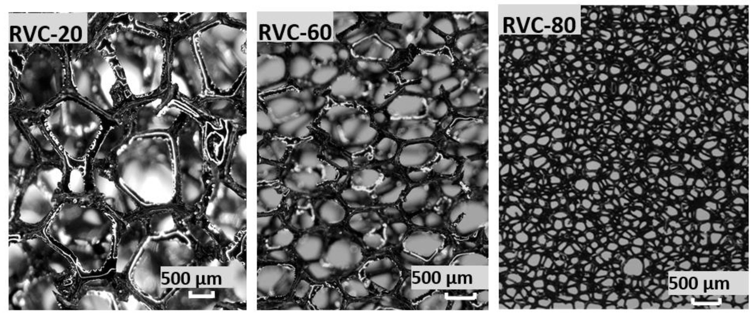
36]. A core in the sandwich panel was made of vitreous carbon foam samples with a different structure determined by the number of pores per 1 cm of 8, 24, and 32, hereinafter referred to as RVC-20, RVC-60, and RVC-80 (ERG Aerospace Corporation (USA)) (
Figure 2). The porosity of the materials was 0.97. The average values of the structure parameters of vitreous carbon foam samples with various numbers of pores per 1 cm were determined as a result of studies of the structure of these materials using a stereoscopic microscope equipped with a digital video camera (
Table 1).
Thermal tests were carried out under conditions of unsteady radiation-conductive heating at a pressure of ~0.01 Pa in the temperature range of 297–1273 K. Experimental data included the thermal state parameters (unsteady one-dimensional temperature field) of a three-layer sandwich panel and the electrical parameters of a heating element.
The implementation of the specified thermal regime of the panel was provided by the experimental module EM-2B used in the high-temperature thermovacuum stand TVS-1M. A methodical approach for the investigation of highly porous cellular materials’ thermal properties has been reported previously in [
37,
38].
Thermal tests were carried out in three stages:
Stage 1—Preparation and thermal testing of a sandwich panel with the RVC-20 core;
Stage 2—Preparation and thermal testing of a sandwich panel with the RVC-60 core;
Stage 3—Preparation and thermal testing of a sandwich panel with the RVC-80 core.
At each stage, the following tasks were solved:
- (1)
A methodology of thermal tests was developed;
- (2)
Experimental samples, thermal sensors, and elements of the experimental module (EM) were made in accordance with the requirements for them;
- (3)
The geometric parameters and the density of the vitreous carbon foam samples were determined;
- (4)
The structure parameters of vitreous carbon foam samples were studied;
- (5)
The control and measuring lines of the automated system for scientific research of thermophysical processes and the systems of the thermal vacuum stand TVS-1M were checked and prepared for thermal tests;
- (6)
The experimental module EM-2V was assembled and installed in the vacuum chamber of the stand;
- (7)
Preliminary thermal tests were carried out to check the operability of the stand systems, to select the heating modes, to debug the three-layer panel heating program, and to remove the adsorbed water;
- (8)
Thermal tests were carried out, during which the temperatures on the surface of the heating element and at the given points of the investigated three-layer panel were determined;
- (9)
The results of the thermal tests were processed and analyzed.
The processing of the obtained experimental information was carried out using the experimental–computational system, developed at the Thermal Laboratory of the Department of Space Systems Engineering, Moscow Aviation Institute.
All tests were carried out under the same conditions (heating modes and pressure in the vacuum chamber of the stand) and with the identical samples of the ceramic material and the heat-insulating elements. In addition, carbon foam samples used in tests had similar thicknesses (
Table 2). Thus, the results of the thermal tests make it possible to compare the heat-insulating properties of vitreous carbon foam samples with different microstructures and to evaluate the effect of the materials’ morphologies on their physical properties.
The investigated materials RVC-20, RVC-60, and RVC-80 had a three-dimensional spatial microstructure with open pores (
Figure 1). The unit cell of the material structure had a shape close to a pentagondodecahedron, consisting of twelve pentagonal faces, at the vertices of which there were junctures, and the edges were formed by struts connecting the junctures. In one juncture, as a rule, four struts were connected, but there were junctures that combined more struts (up to six). The thickness of the strut was variable along the length and increased in the vicinity of the juncture. The sectional shape of the struts was close to an equilateral triangle with concave sides. The elements of the cellular structure (cells, pores, struts, and strut junctures) had different sizes and were arbitrarily oriented in space. There were various defects in the structure of the material, and, as a result, the structure of a real high-porous cellular material could differ significantly from its mathematical model.
The structural element dimensions of the studied materials samples decreased with an increase in the number of pores per 1 cm (
Table 1). The dimensions of the cells depended on the number of pores per linear size more than the dimensions of the struts and strut junctures. The influence of the number of pores per linear size on the dimensions of the material structure elements decreased with an increase in the considered parameter. The materials’ microstructure parameters obtained as a result of statistical processing were taken into account when calculating the conductive λ
c and radiative λ
R components of thermal conductivity.
Taking into account the mechanical and electrical properties of the materials RVC-20, RVC-60, and RVC-80, as well as the significant hardness of the ceramic plates, microthermocouples with a diameter of 0.1 mm were installed on the heated and reverse surfaces of the ceramic plates in specially cut grooves that were 170 μm deep. Grooves with thermocouples were filled with a specially prepared composition based on ceramic material powder (90%) with a working temperature of 1573 K. Outside the plates, thermocouple wires were electrically insulated.
During thermal tests, a symmetrical scheme was implemented (
Figure 3) with conductive-radiation heating of two identical experimental assemblies, A and B, including a high-porous cellular material core (
Table 2) and layers of high-temperature ceramic material. This test scheme allowed for the determination of heat flux on the surface of the heating element (
Figure 4) by its electrical parameters [
38]:
where
I(τ) is the current in the heating element circuit;
U(τ) is the voltage at the boundaries of the heating element operating zone; S = 0.005 m
2 is the heating element operating zone area;
δh = 0.0001 m is the heating element thickness;
Th(τ) is the heating element temperature;
τ is time;
τe is the end time of the measurements (tests); and
ρh and
ch are the density and heat capacity of the heating element’s material:
ρh = (7902 − 0.0584 ×
Th) kg/m
3;
ch (T) = (500 + 0.1744 ×
Th) J/(kg·°C).
Experimental assemblies A (upper) and B (lower) with installed thermocouples T1, T2, T3, and T4 and T6, T7, T8, and T9 were located on the heating element of the experimental module EM-2V (
Figure 3). Experimental assemblies were installed in heat-insulating holders 5 made of high-temperature ceramic heat-insulating material based on SiO
2 fibers (
Figure 4). The assembled experimental module was installed on the water-cooled working table of the thermal vacuum stand TVS-1M vacuum chamber (
Figure 4).
The results of the thermal tests showed that:
- (1)
The temperature changing program specified for the heating element was successfully implemented in the temperature range from room temperature to 1273 K.
- (2)
In the thermal tests of stage 1, a good agreement of the temperatures was obtained at the corresponding symmetrical points T1 and T6 and T2 and T7, indicating a good implementation of the symmetrical heating scheme of the experimental assemblies. However, a significant (up to 100 K) divergence of the temperatures was observed at the corresponding symmetrical points T3 and T8 and T4 and T9, which increased with increasing temperature. This discrepancy is explained by a significant difference (up to 10%) in the densities of RVC-20 samples A and B. At high temperatures, radiation becomes the dominant heat transfer mechanism in a highly porous carbon material, and sample A with greater density heats up more slowly.
In the thermal tests of stages 2 and 3, the temperatures at the symmetrical points of the experimental assemblies A and B had similar values, indicating a good implementation of the symmetrical heating scheme of the three-layer model panels. Because the densities of samples A and B for materials RVC-60 and RVC-80 were practically the same, it can be assumed that the values of the thermophysical properties of these materials also coincide.
- (3)
Highly porous open-cell carbon foam specimens did not have noticeable signs of destruction after repeated heating (including heating, preliminary, and standard tests) up to a temperature of ~1273 K in vacuum.
- (4)
During the preliminary tests of experimental assemblies, a significant change in pressure in the vacuum chamber of the TVS-1M stand was observed, which was associated with the release of adsorbed water from open-cell carbon foam samples and heat-insulating elements, as well as volatile components from the technological materials used.
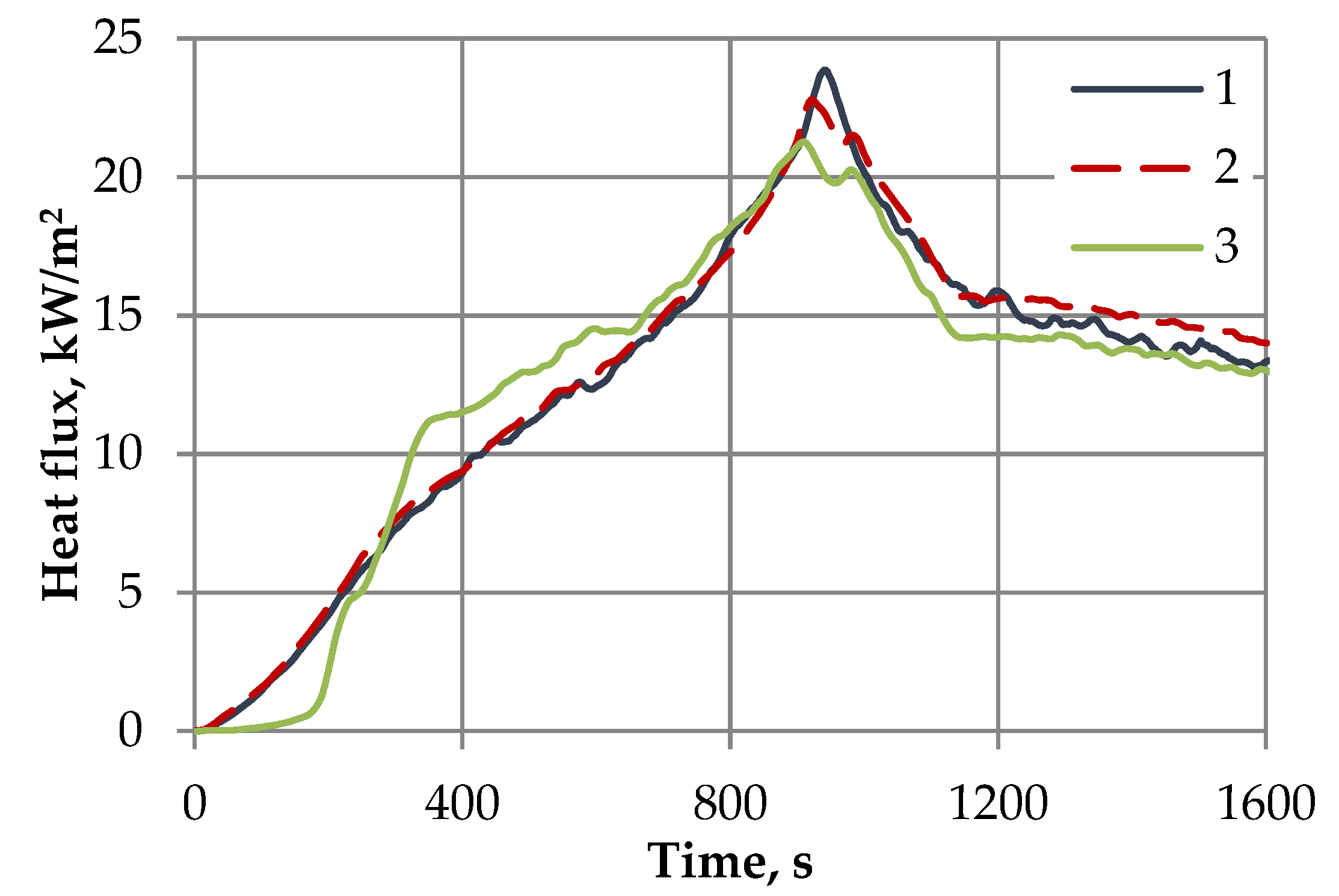
The time dependences of the heat flux on the heating element coincided in all three tests of experimental assemblies with high-porous cellular materials samples RVC-20, RVC-60, and RVC-80 (
Figure 5). On the heated surface of the RVC-20 sample, lower values of temperature T
2 were realized; however, this sample heated up much faster than the others (especially at high temperatures), as evidenced by the nature of the change in temperature T
3 on the back surface of the sample (
Figure 6). Thus, the material RVC-20 with the largest average cell diameter exhibited the worst thermal insulation properties.
The heated surface temperature T2 of the highly porous open-cell carbon material sample increased with an increase in the number of pores per 1 cm (decrease in the material’s average cell diameter) at temperatures exceeding ~800 °C.
The back surface temperature of the highly porous open-cell carbon material sample T3 at high temperatures dropped significantly with an increase in the number of pores by 1 cm. Thus, high-porous cellular materials with the smallest cell size demonstrated the best thermal insulation properties at high temperatures, and the radiation component of thermal conductivity increased significantly.
The thermal tests results obtained for two experimental assemblies can be considered the results of two separate (independent) tests of highly porous materials samples A and B. At the same time, in order to build a more accurate mathematical model of heat transfer in a highly porous materials structure, this experimental information should be supplemented with the results of thermal tests carried out under the other conditions (heating modes and pressure in the vacuum chamber of the stand).
The results of the tests are the source data for solving the test optimal design problem. A statement implies the determination of the open-cell carbon foam layer thickness together with the cell diameter [
35]. The design parameters should ensure allowable maximum temperature on the back surface of the panel and a minimum of the total mass of the system (
Figure 7).
The allowable temperature of the back surface of the sandwich panel was limited to 766 K, which was implemented in the tests of the RVC-80 vitreous carbon foam sample. The minimum cell diameter was limited to 0.656 mm, corresponding to a sample of RVC-80. As the initial condition in the boundary-value problem, the temperature distribution in the three-layer panel at the initial time moment was set. The boundary condition on the heated surface of the sandwich panel was the heat flux on the heating element obtained in thermal tests (
Figure 5). It was assumed that the heat flux on the panel’s back surface was equal to 0.
The results of mathematical modeling demonstrate a good agreement with the experimental data (
Figure 8,
Figure 9 and
Figure 10). The results of the comparison of the obtained experimental and calculated temperatures confirm that the presented method of mathematical modeling of radiative-conductive heat transfer can be used in the algorithm of optimal design of a multilayer thermal protection, taking into account the morphology of highly porous cellular materials. The noticeable difference between the theoretical and experimental results for the RVC-20 sample can be explained by the fact that this material is not an optically thick medium, so the Rosseland approximation used for the conductivity radiative component calculation leads to significant inaccuracy.
The experimental and calculated temperatures are almost the same at temperatures below 1000 K, while at higher temperatures, the difference between them increases significantly. Thus, for the design of heat protection systems operating at temperatures above 1000 K, a more accurate analysis of radiative heat transfer in porous media is required.
In this problem, the optimal thickness of the porous layer is 15.9 mm, and the cell diameter is 0.656. The obtained optimal parameters of the porous layer closely correspond to the parameters of the vitreous carbon foam sample RVC-80 used in the experiment. These results fully correspond to the experimental data, according to which the material with the minimum dimensions of the microstructure has the best thermal insulation properties. Thus, the thermal experiment conducted allows for justification of the efficiency and reliability of the developed optimization technique and the software implementing this algorithm.


