
Effects of Static Stability Margin on Aerodynamic Design Optimization of Truss-Braced Wing Aircraft

Abstract
:1. Introduction
2. Methodology
2.1. CFD Solver
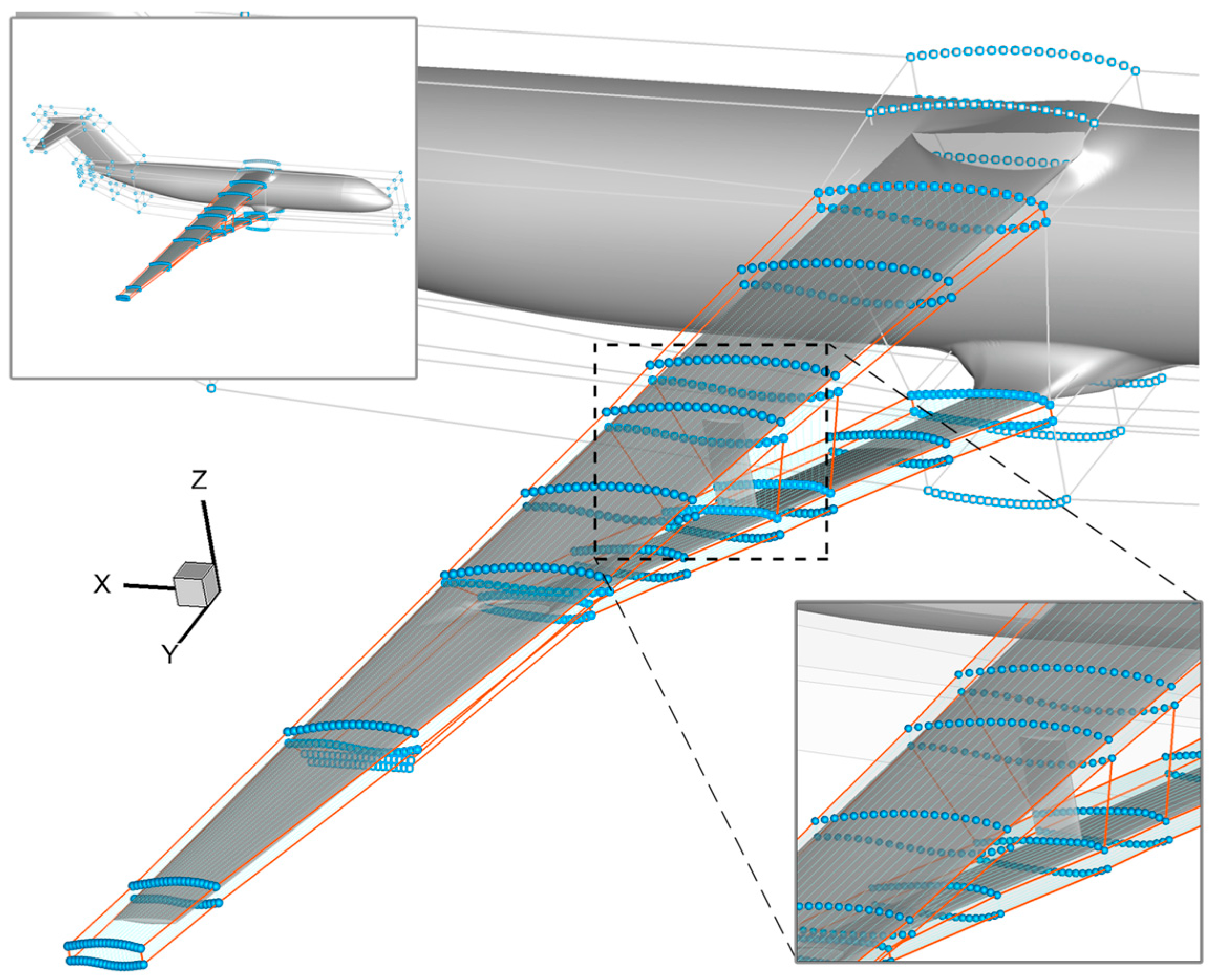
2.2. Geometric Parameterization
2.3. Mesh Deformation Algorithm
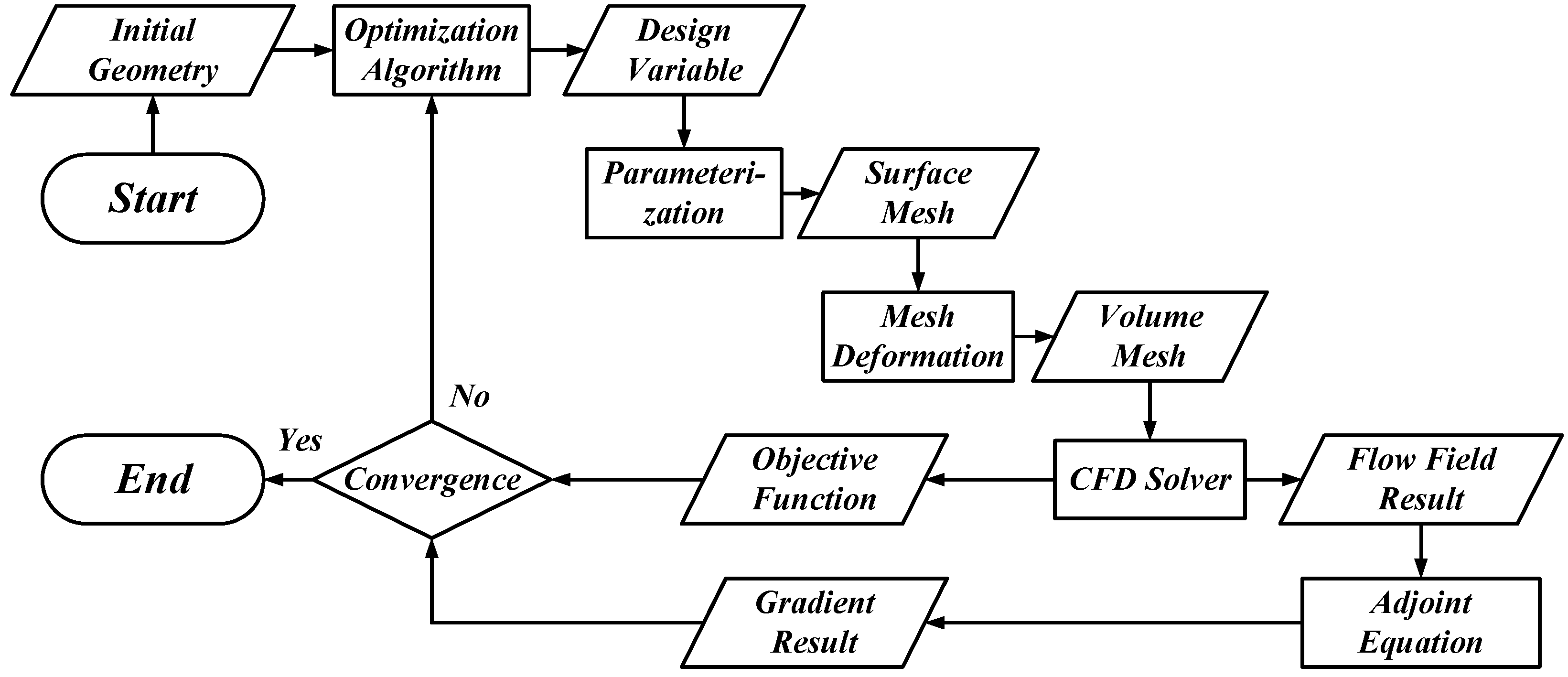
2.4. Gradient-Based Optimization Algorithm
3. Problem Statement
3.1. Static Stability Margin
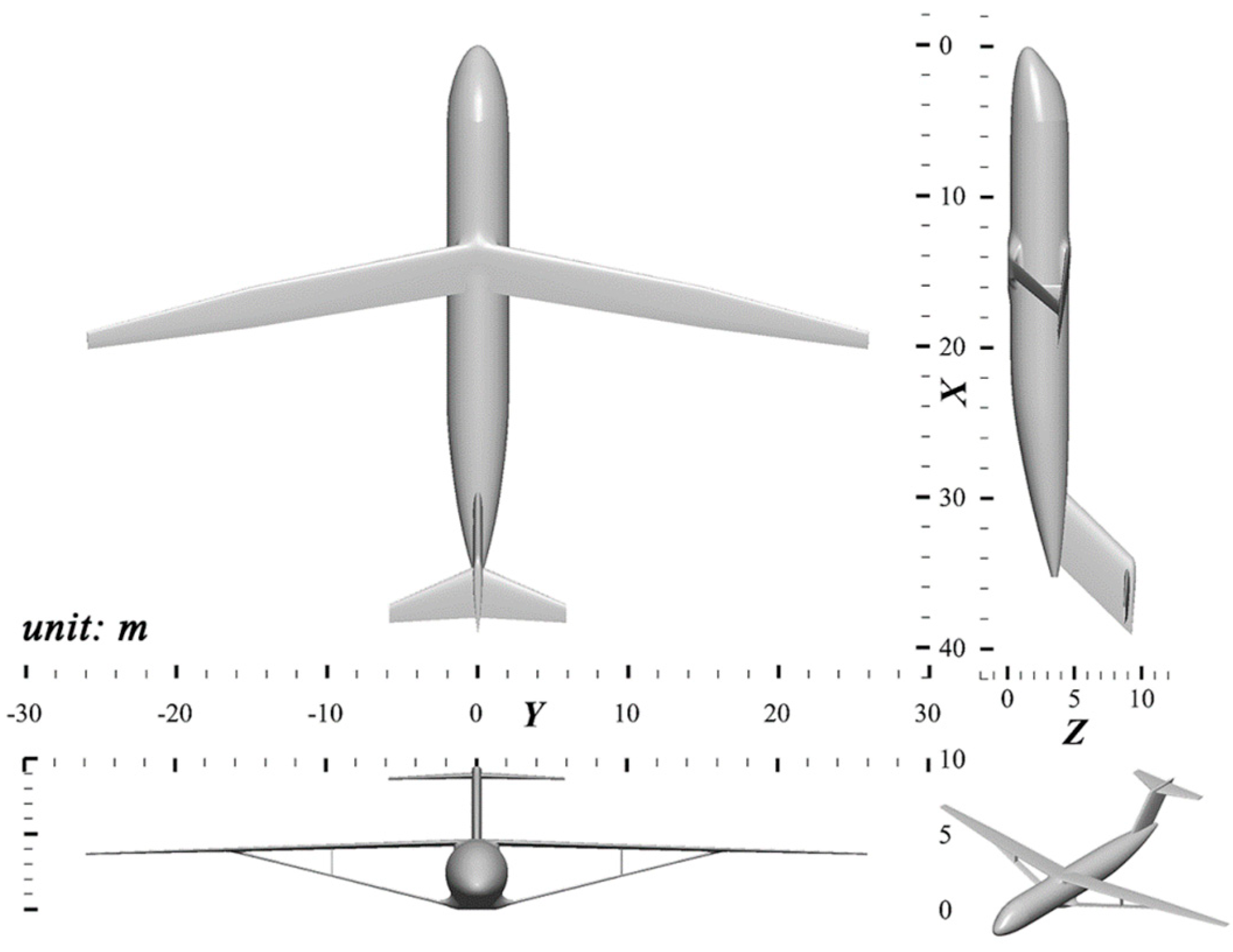
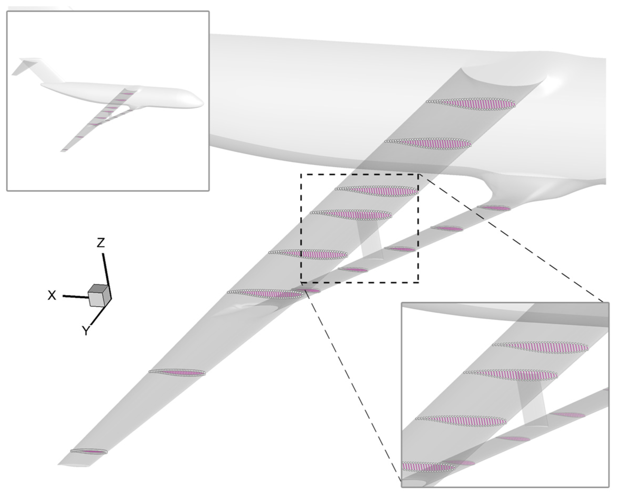
3.2. Baseline Full Configuration Geometry
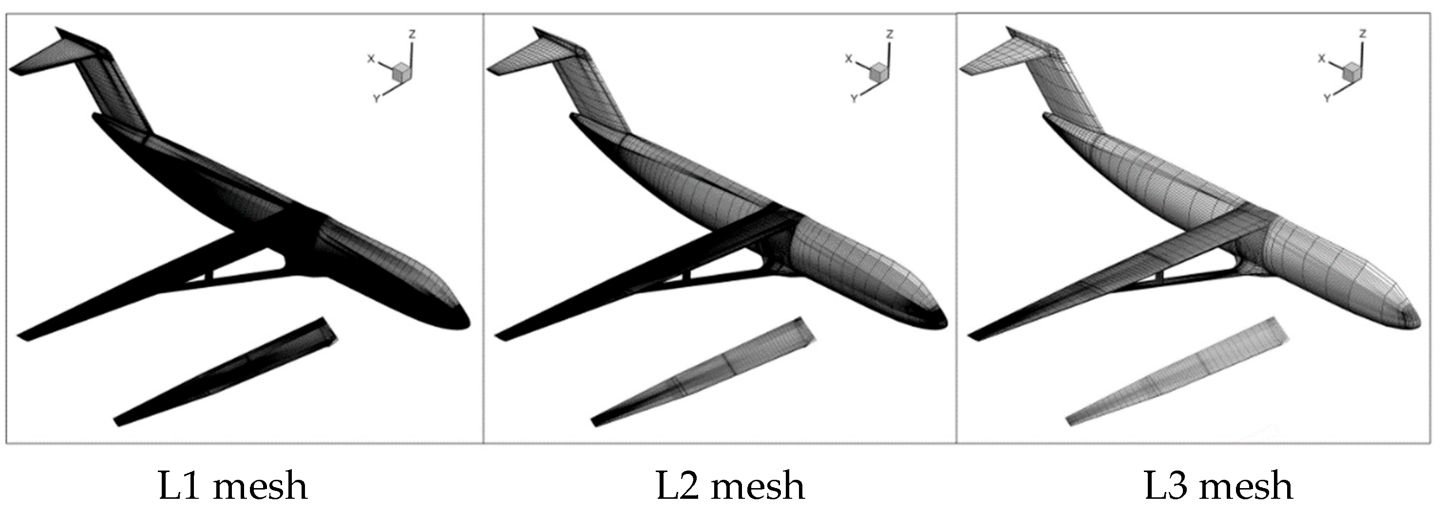
3.3. Computational Grids
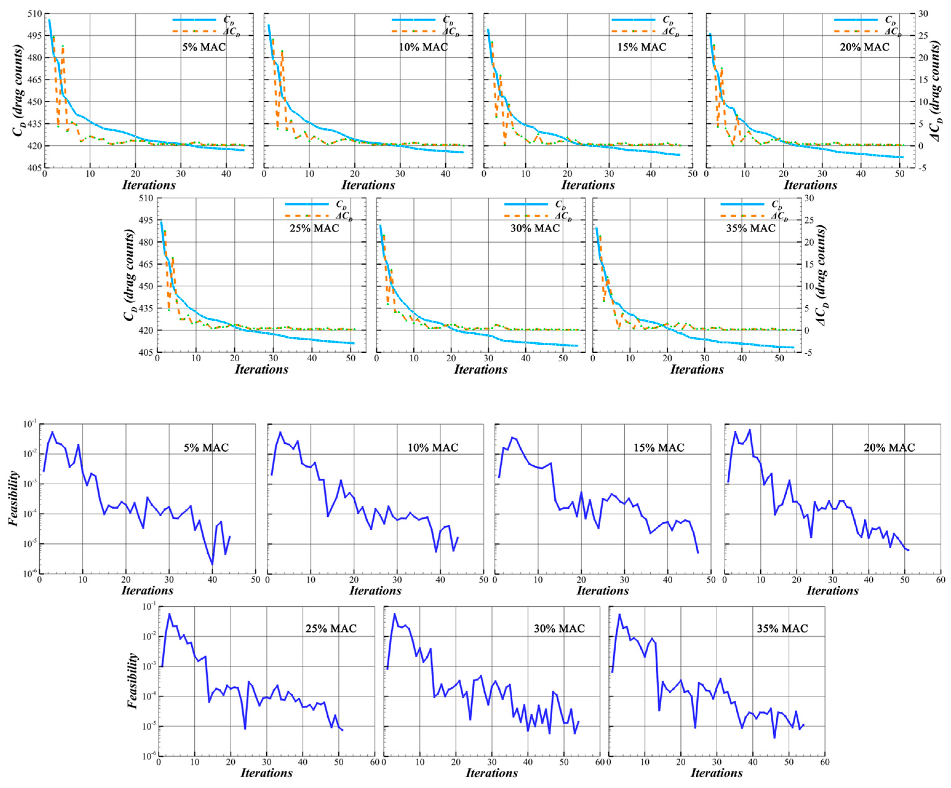
3.4. Study Cases and Optimization Statement
- Study 1: Only Static Stability Margin Effect
- Study 2: Combination of Optimization and Static Stability Margin
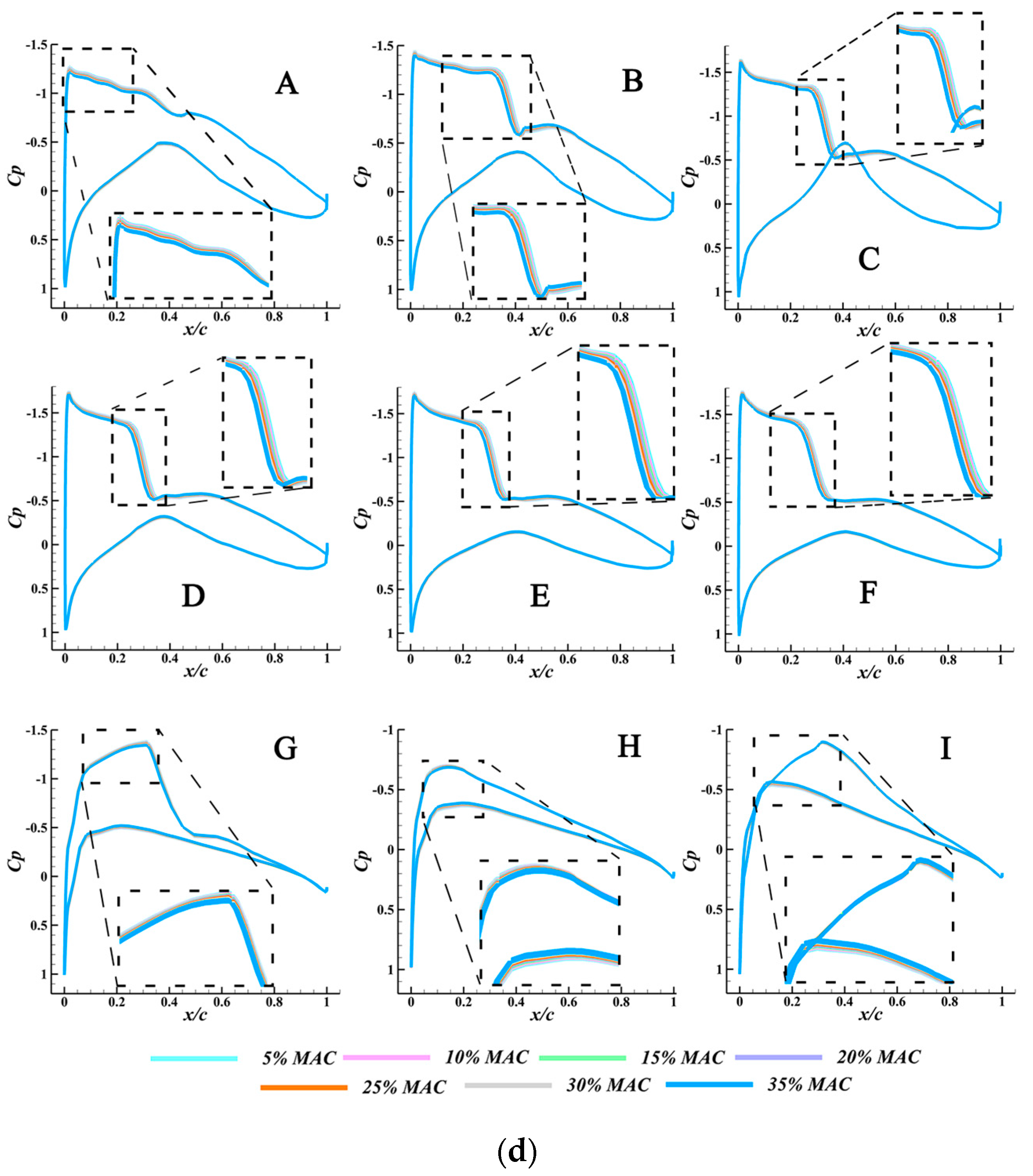
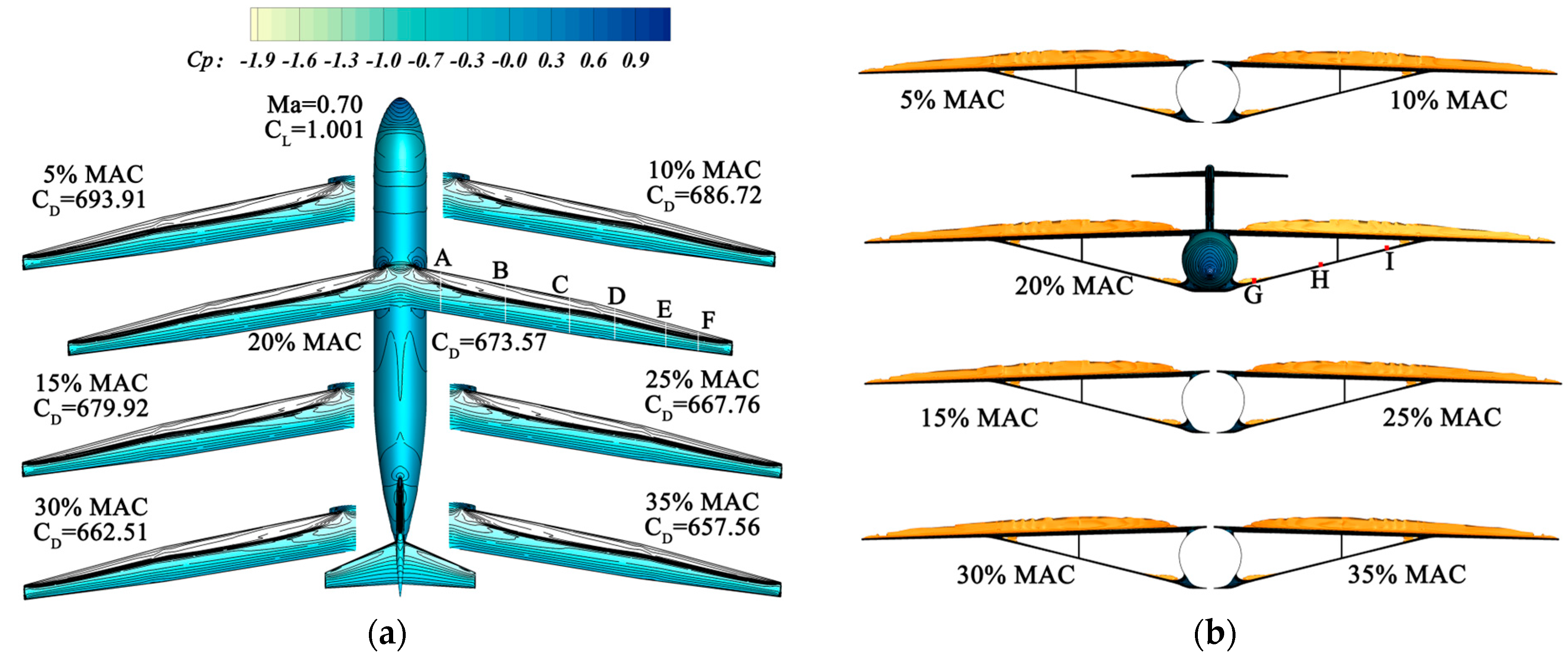
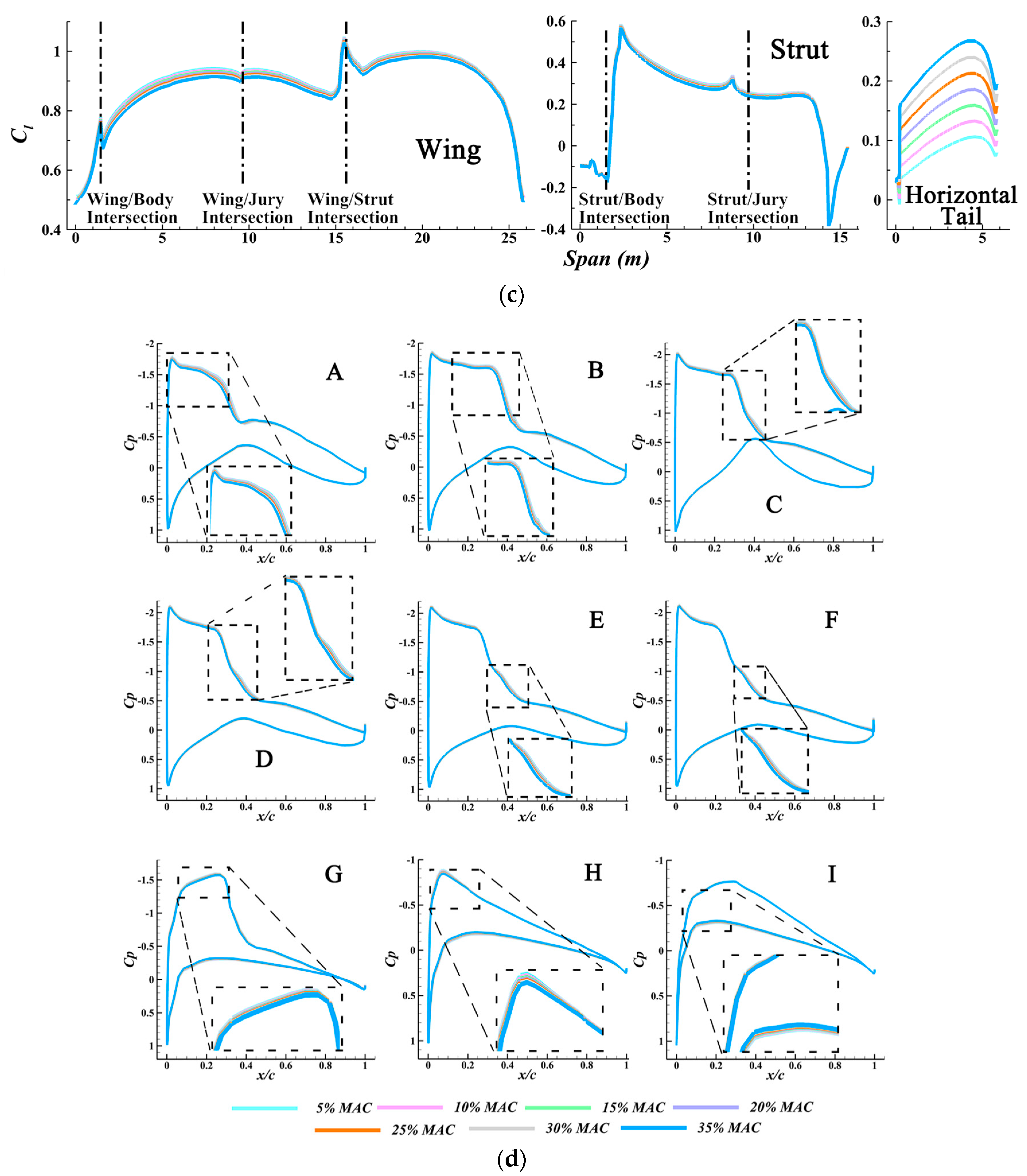
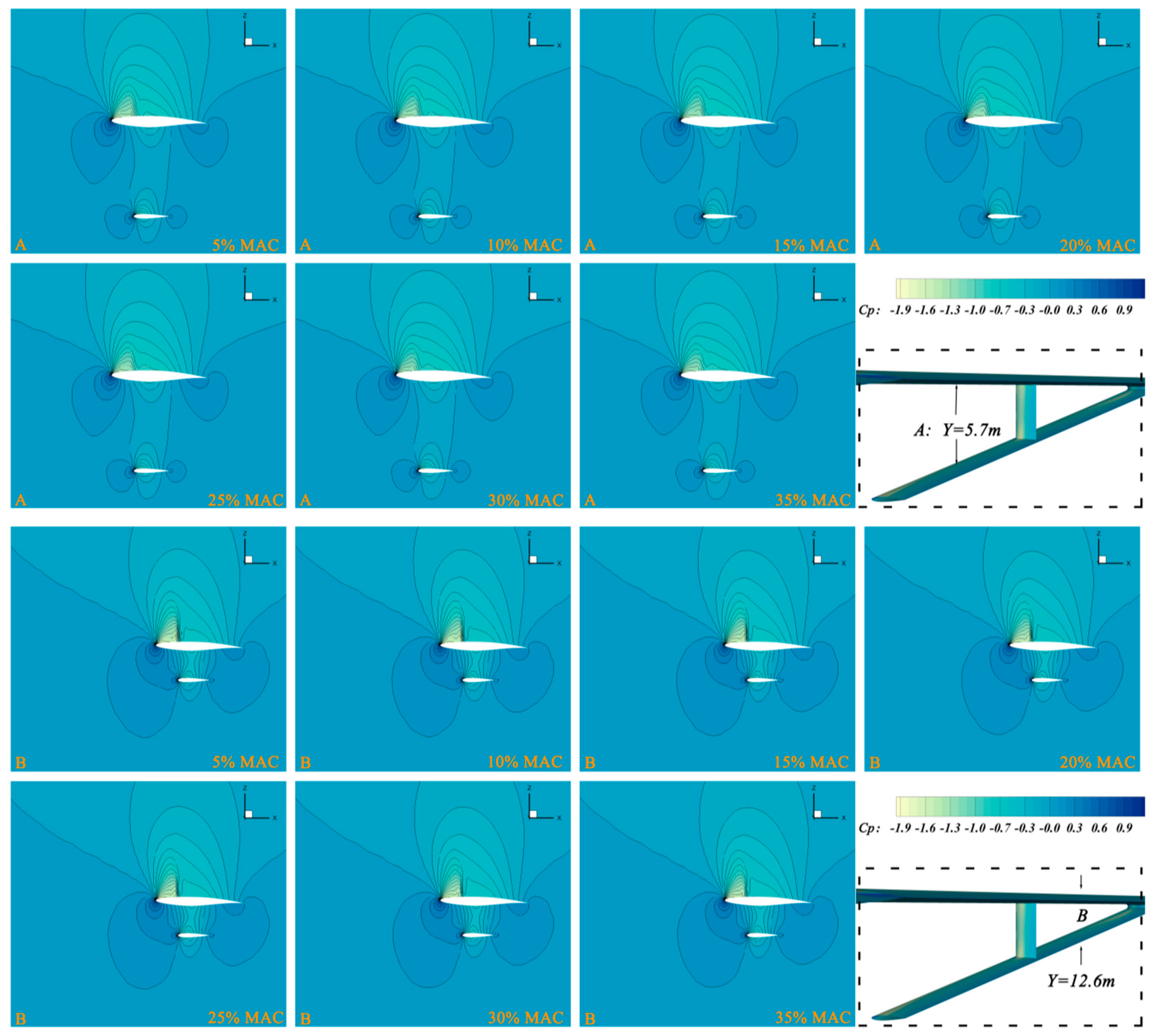
4. Results and Discussions
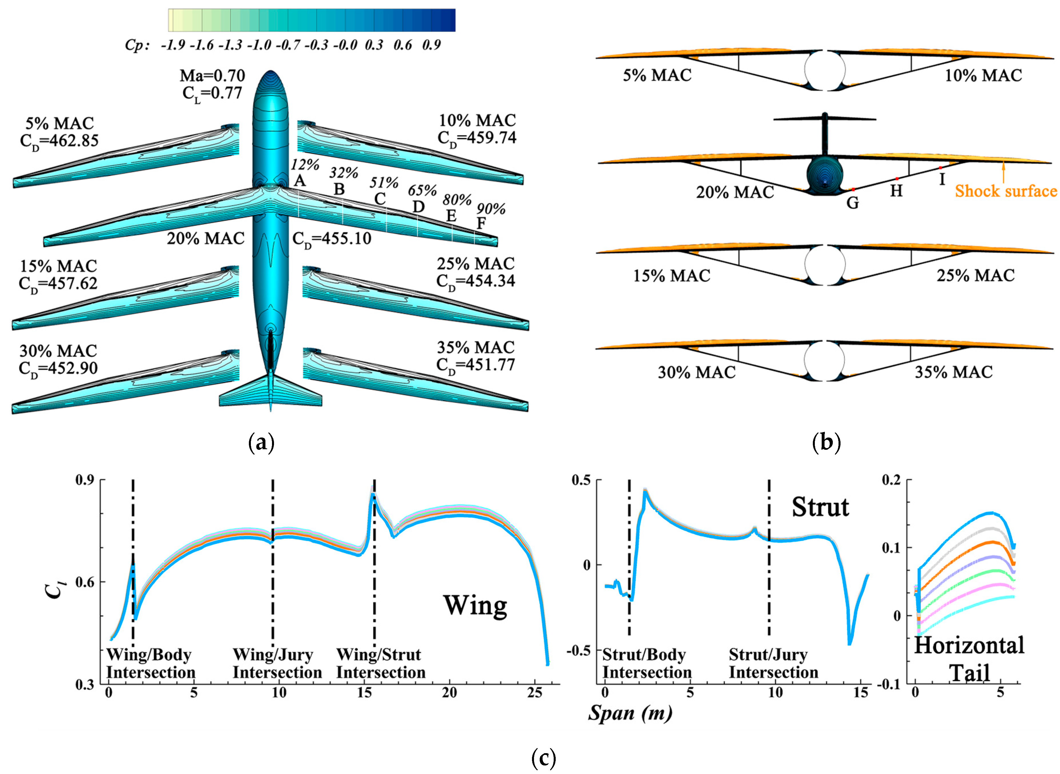
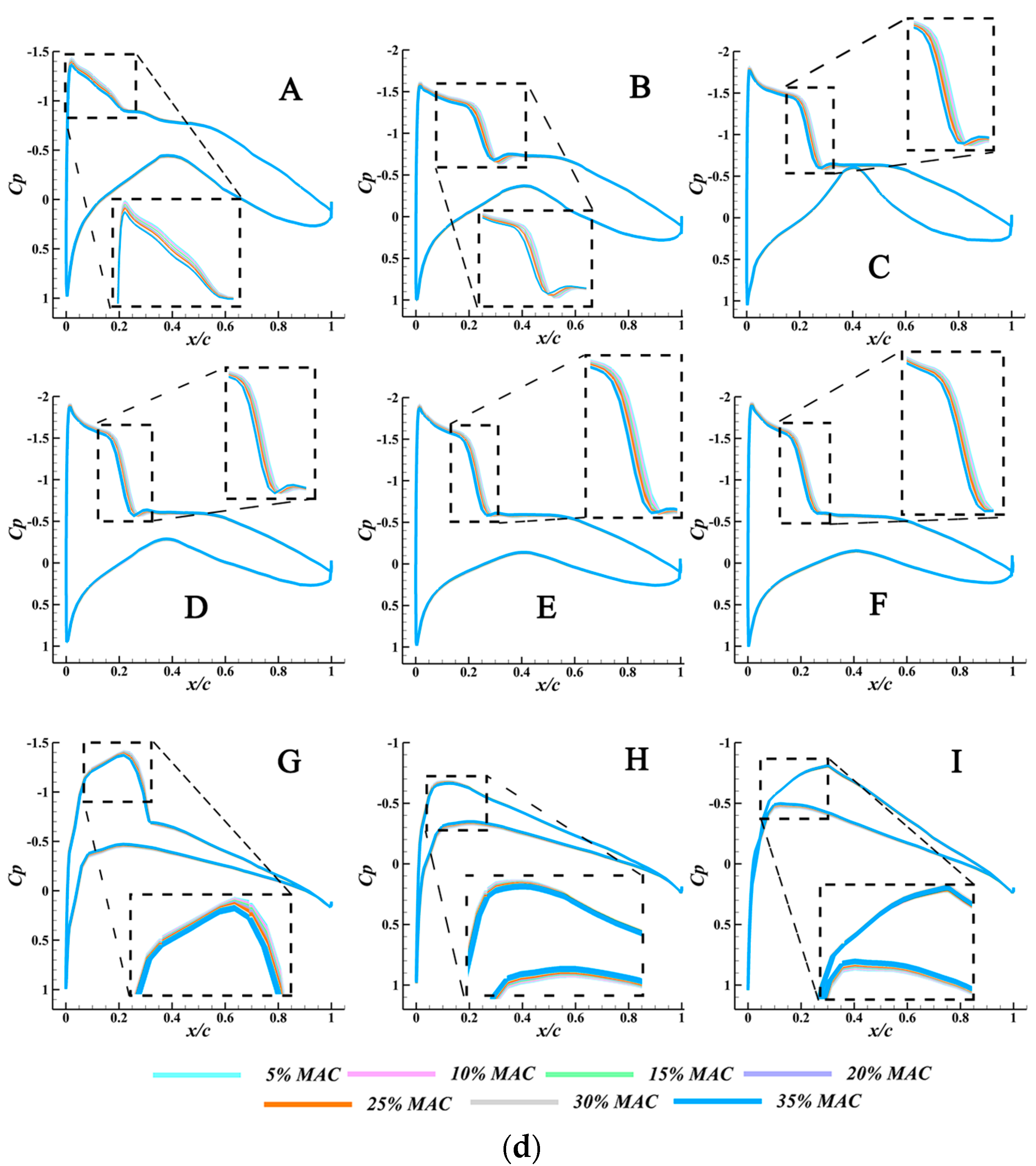
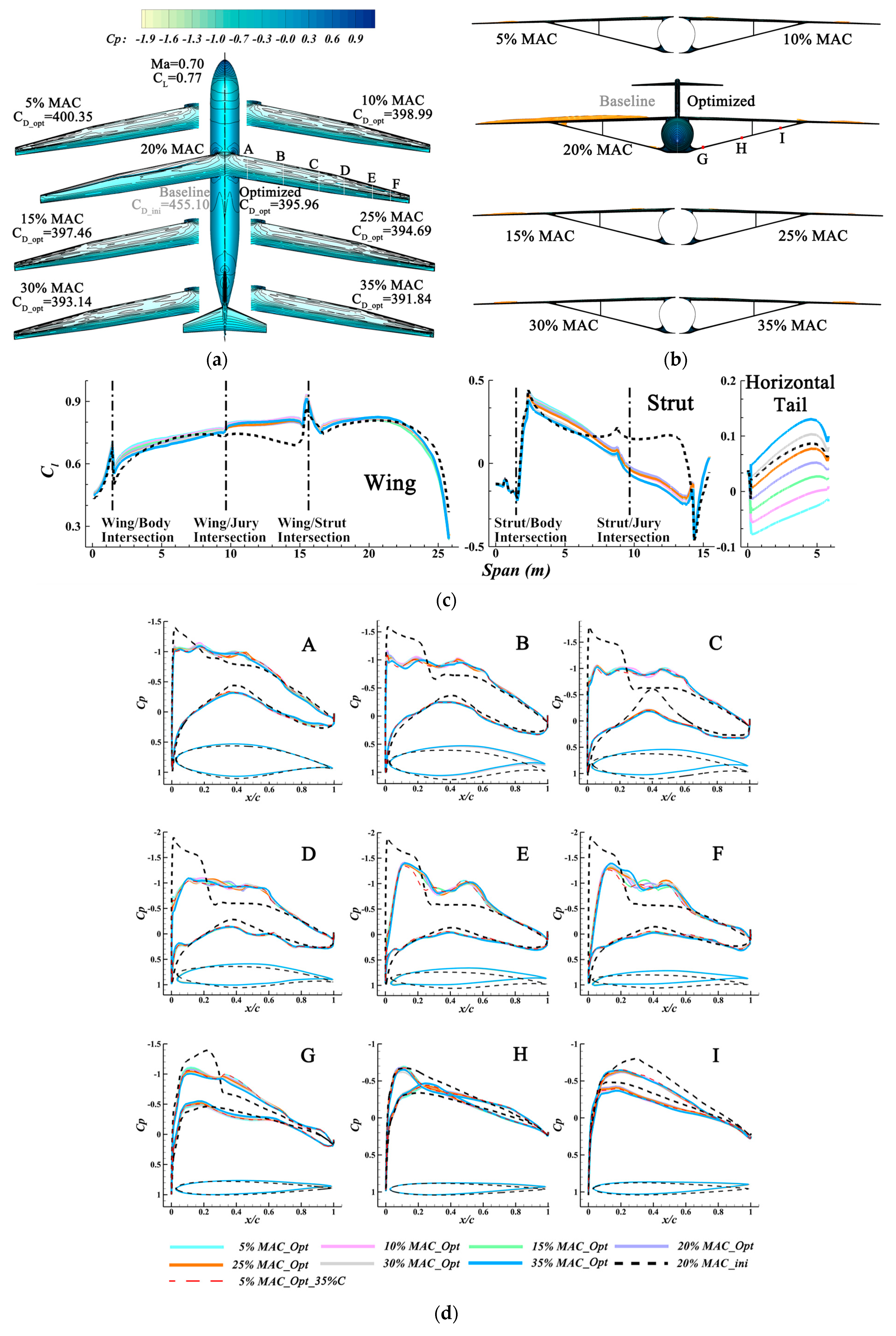
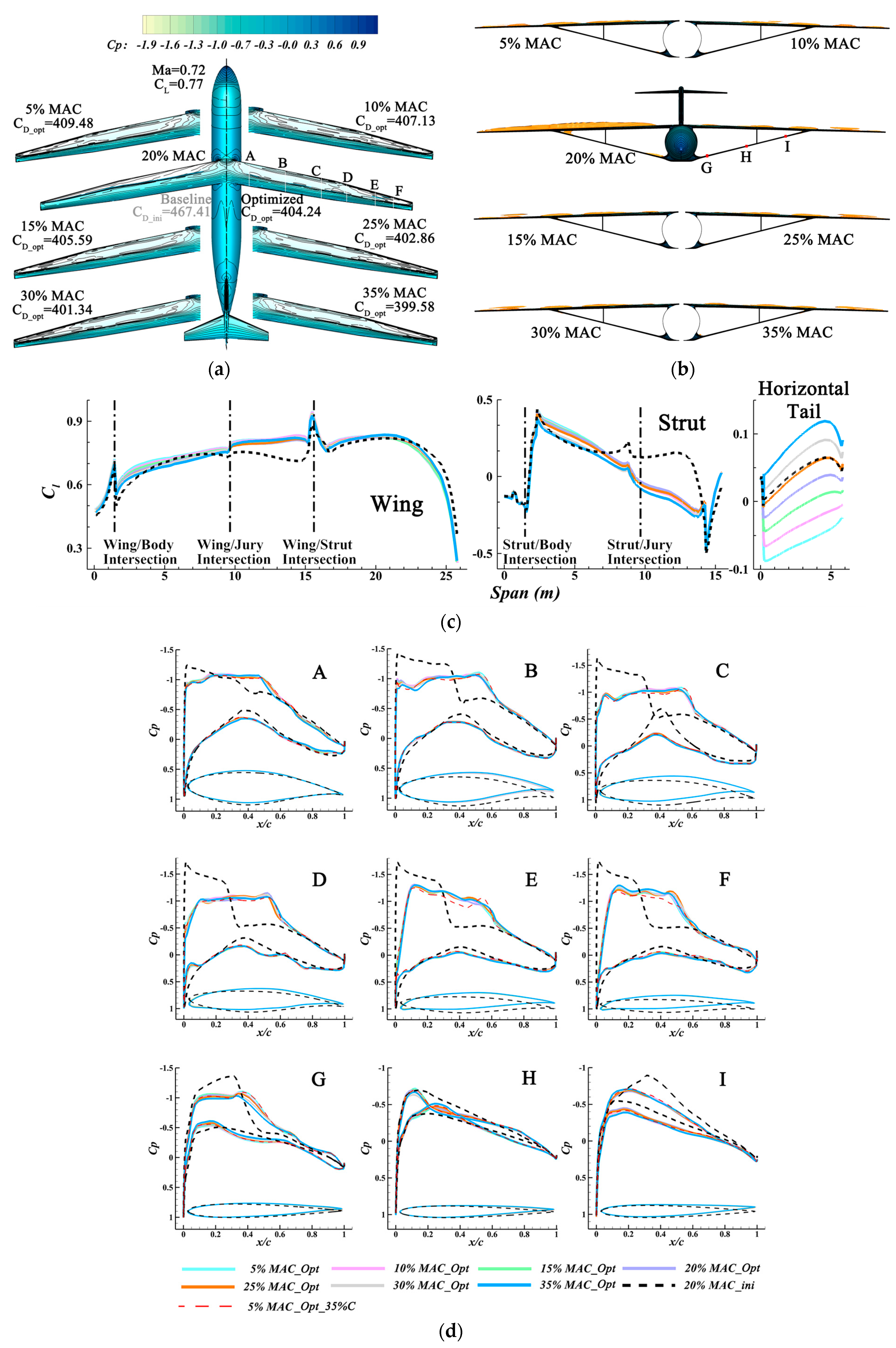
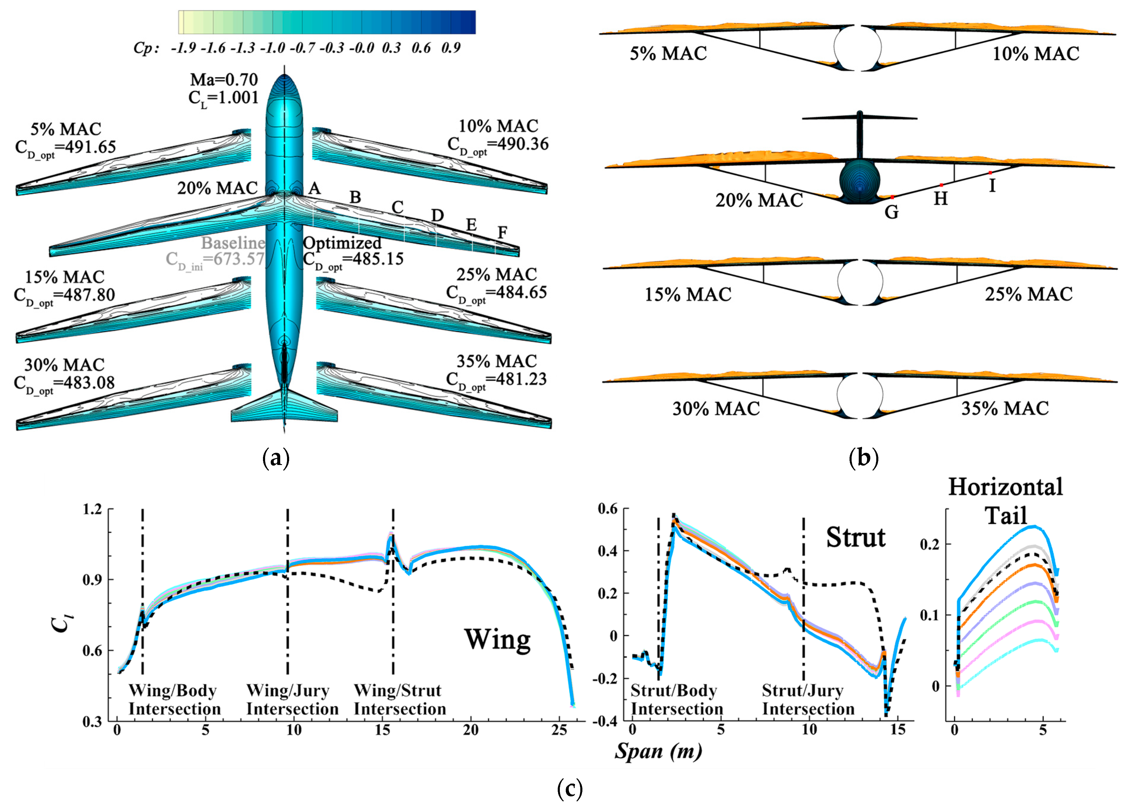
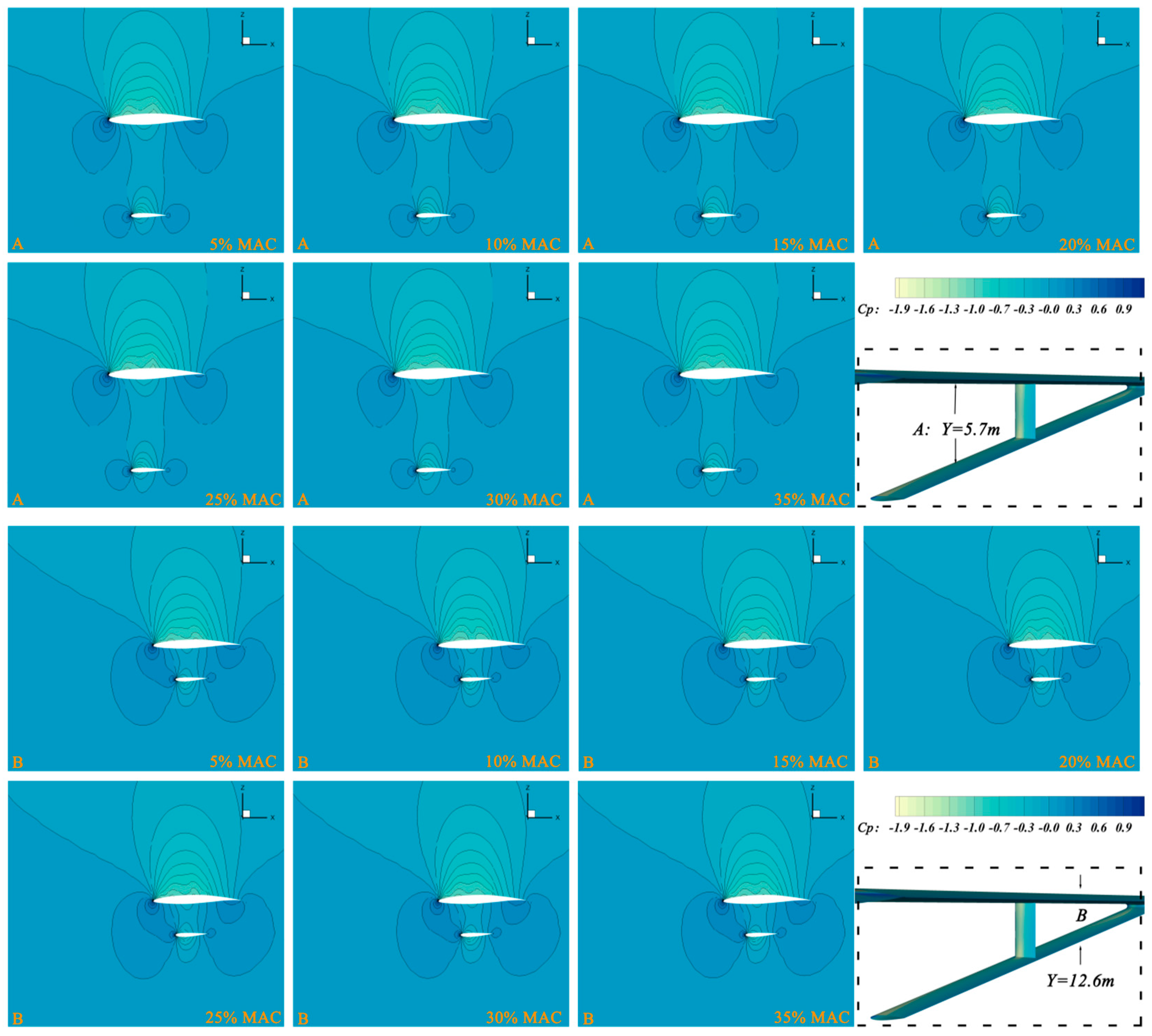
4.1. Only Different Static Stability Margins with Initial Configuration
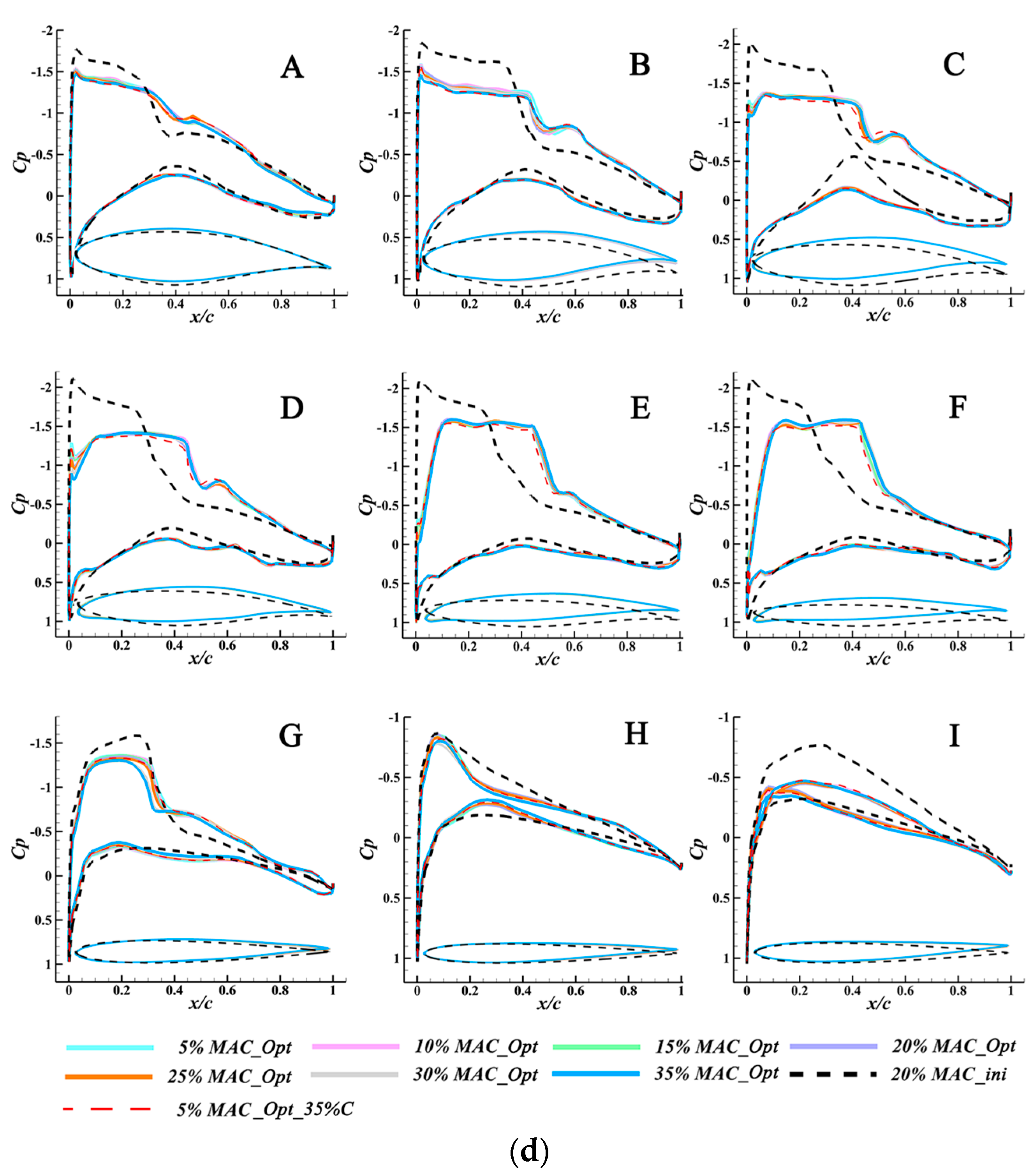
4.2. Combination of Aerodynamic Shape Optimizations and Static Stability Margins
5. Conclusions
Author Contributions
Funding
Data Availability Statement
Conflicts of Interest
Nomenclature
| angle of attack | |
| wing twist angle | |
| strut twist angle | |
| horizontal tail twist angle | |
| a | local sound speed |
| c | thrust specific fuel consumption |
| CD | drag coefficient |
| CL | lift coefficient |
| CLα | derivative of CL with respect to |
| Cmy | pitching moment coefficient |
| Cmα | derivative of Cmy with respect to |
| Cp | pressure coefficient |
| Kn | static longitudinal stability margin |
| L/D | lift-to-drag ratio |
| M | Mach number |
| MAC | mean aerodynamic chord |
| Re | Reynolds number |
| t/c | thickness-to-chord ratio |
| thickness constraints | |
| xn | locations of the neutral point |
| xCG | location of the center of gravity |
| FFD control points |
References
- Chen, Z.L.; Zhang, M.H.; Chen, Y.C.; Sang, W.M.; Tan, Z.G.; Li, D.; Zhang, B.Q. Assessment on critical technologies for conceptual design of blended-wing-body civil aircraft. Chin. J. Aeronaut. 2019, 32, 1797–1827. [Google Scholar] [CrossRef]
- Karpuk, S.; Ma, Y.; Elham, A. Design Investigation of Potential Long-Range Hydrogen Combustion Blended Wing Body Aircraft with Future Technologies. Aerospace 2023, 10, 566. [Google Scholar] [CrossRef]
- Lee, D.S.; Fahey, D.W.; Skowron, A.; Allen, M.R.; Burkhardt, U.; Chen, Q.; Doherty, S.J.; Lim, L.L.; Freeman, S.; Forster, P.M.; et al. The Contribution of Global Aviation to Anthropogenic Climate Forcing for 2000 to 2018. Atmos. Environ. 2021, 244, 117834. [Google Scholar] [CrossRef] [PubMed]
- Bradley, M.K.; Droney, C.K. Subsonic Ultra Green Aircraft Research: Phase I Final Report; CR-2011-216847; NASA: Washington, DC, USA, 2011. [Google Scholar]
- Bradley, M.K.; Droney, C.K. Subsonic Ultra Green Aircraft Research Phase II: N + 4 Advanced Concept Development; CR-2012-217556; NASA: Washington, DC, USA, 2012. [Google Scholar]
- Bradley, M.K.; Droney, C.K.; Allen, T.J. Subsonic Ultra Green Aircraft Research: Phase II—Volume I—Truss Braced Wing Design Exploration; CR–2015-218704; NASA: Washington, DC, USA, 2015; Volume I. [Google Scholar]
- Bradley, M.K.; Droney, C.K. Subsonic Ultra Green Aircraft Research: Phase II—Volume II—Hybrid Electric Design Exploration; CR–2015-218704; NASA: Washington, DC, USA, 2015; Volume II. [Google Scholar]
- International Air Transport Association. IATA Technology Roadmap, 4th ed.; International Air Transport Association: Montreal, QC, Canada, 2013. [Google Scholar]
- International Air Transport Association. IATA Technology Roadmap to 2050; International Air Transport Association: Montreal, QC, Canada, 2019. [Google Scholar]
- International Civil Aviation Organization (ICAO). Consolidated Statement of Continuing ICAO Policies and Practices Related to Environmental Protection—Global Market-Based Measure (MBM) Scheme; International Civil Aviation Organization (ICAO): Montreal, QC, Canada, 2016. [Google Scholar]
- ICAO. 37th Assembly Working Papers, A37-WP/402; ICAO: Montreal, QC, Canada, 2010. [Google Scholar]
- Innovation Takes off, Clean Sky European Research for Aeronautics. Clean Sky Book; Le Cherche Midi: Paris, France, 2016. [Google Scholar]
- Krein, A.; Williams, G. Flightpath 2050: Europe’s vision for aeronautics. Innovation for Sustainable Aviation in a Global Environment. In In Proceedings of the Sixth European Aeronautics Days, Madrid, Spain, 30 March–1 April 2011. [Google Scholar]
- Abbas, A.; De Vicente, J.; Valero, E. Aerodynamic Technologies to Improve Aircraft Performance. Aerosp. Sci. Technol. 2013, 28, 100–132. [Google Scholar] [CrossRef]
- Bravo-Mosquera, P.D.; Catalano, F.M.; Zingg, D.W. Unconventional Aircraft for Civil Aviation: A Review of Concepts and Design Methodologies. Prog. Aerosp. Sci. 2022, 131, 100813. [Google Scholar] [CrossRef]
- Cavallaro, R.; Demasi, L. Challenges, Ideas, and Innovations of Joined-Wing Configurations: A Concept from the Past, an Opportunity for the Future. Prog. Aerosp. Sci. 2016, 87, 1–93. [Google Scholar] [CrossRef]
- Li, L.; Bai, J.Q.; Qu, F. Multipoint Aerodynamic Shape Optimization of a Truss-Braced-Wing Aircraft. J. Aircr. 2022, 59, 1179–1194. [Google Scholar] [CrossRef]
- Gundlach, J.F.; Tetrault, P.-A.; Gern, F.H.; Naghshineh-Pour, A.H.; Ko, A.; Schetz, J.A.; Mason, W.H.; Kapania, R.K.; Grossman, B.; Haftka, R.T. Multidisciplinary design optimization of a strut-braced wing transonic transport. In Proceedings of the 38th AIAA Aerospace Sciences Meeting and Exhibit, Reno, NV, USA, 10–13 January 2000. [Google Scholar]
- Gur, O.; Bhatia, M.; Schetz, J.A.; Mason, W.H.; Kapania, R.K.; Mavris, D.T. Design optimization of a truss-braced-wing transonic transport aircraft. J. Aircr. 2010, 47, 1907–1917. [Google Scholar] [CrossRef]
- Mallik, W.; Kapania, R.K.; Schetz, J.A. Effect of flutter on the multidisciplinary design optimization of truss-braced-wing aircraft. J. Aircr. 2015, 52, 1858–1872. [Google Scholar] [CrossRef]
- Bhatia, M.; Kapaniay, R.K.; Haftka, R.T. Structural and aeroelastic characteristics of truss-braced wings: A Parametric Study. J. Aircr. 2012, 49, 302–310. [Google Scholar] [CrossRef]
- Nguyen, N.; Fugate, J.; Xiong, J.T.; Kaul, U. Flutter analysis of the transonic truss-braced wing aircraft using transonic correction. In Proceedings of the AIAA SciTech 2019 Forum, San Diego, CA, USA, 7–11 January 2019. [Google Scholar]
- Chau, T.; Zingg, D.W. Aerodynamic Optimization and Fuel Burn Evaluation of a Transonic Strut-Braced-Wing Single-Aisle Aircraft. J. Aircr. 2023, 1–21. [Google Scholar] [CrossRef]
- Lee, K.; Kang, S. Propulsion System Modeling and Reduction for Conceptual Truss-Braced Wing Aircraft Design. Int. J. Aeronaut. Space Sci. 2017, 18, 651–661. [Google Scholar] [CrossRef]
- Ting, E.; Reynolds, K.; Nguyen, N.; Totah, J. Aerodynamic analysis of the truss-braced wing aircraft using vortex-lattice superposition approach. In Proceedings of the 32nd AIAA Applied Aerodynamics Conference, Atlanta, GA, USA, 16–20 June 2014. [Google Scholar]
- Gur, O.; Schetz, J.A.; Mason, W.H. Aerodynamic considerations in the design of truss-braced-wing aircraft. J. Aircr. 2011, 48, 919–939. [Google Scholar] [CrossRef]
- Demasi, L.; Monegato, G.; Cavallaro, R.; Rybarczyk, R. Minimum induced drag conditions for truss-braced wings. AIAA J. 2018, 56, 4669–4684. [Google Scholar] [CrossRef]
- Gagnon, H.; Zingg, D.W. Euler-Equation-Based Drag Minimization of Unconventional Aircraft Configurations. J. Aircr. 2016, 53, 1361–1371. [Google Scholar] [CrossRef] [Green Version]
- Secco, N.R.; Martins, J.R.R.A. RANS-Based Aerodynamic Shape Optimization of a Strut-Braced Wing with Overset Meshes. J. Aircr. 2019, 56, 217–227. [Google Scholar] [CrossRef]
- Newman, B.; Buttrill, C. Conventional flight control for an aeroelastic, relaxed static stability high-speed transport. In Proceedings of the Guidance, Navigation, and Control Conference, Baltimore, MD, USA, 7–10 August 1995. [Google Scholar]
- Urie, D.M.; Reaser, J.S. Aerodynamic development of a small horizontal tail for an active control relaxed stability transport application. In Proceedings of the 5th Atmospheric Flight Mechanics Conference for Future Space Systems, Boulder, CO, USA, 6–8 August 1979. [Google Scholar]
- Li, L.; Bai, J.Q.; Guo, T.B.; Chen, S. Aerodynamic Optimization Design for Civil Aircraft Considering Relaxed Static Stability. Acta Aeronaut. Astronaut. Sin. 2017, 38, 121112. (In Chinese) [Google Scholar]
- Zhang, M.H.; Chen, Z.L.; Tan, Z.G.; Gu, W.T.; Li, D.; Yuan, C.S.; Zhang, B.Q. Effects of stability margin and thrust specific fuel consumption constrains on multi-disciplinary optimization for blended-wing-body design. Chin. J. Aeronaut. 2019, 32, 1604–1617. [Google Scholar] [CrossRef]
- Reist, T.A.; Zingg, D.W.; Rakowitz, M.; Potter, G.; Banerjee, S. Multifidelity optimization of hybrid wing-body aircraft with stability and control requirements. J. Aircr. 2019, 56, 442–456. [Google Scholar] [CrossRef]
- Zhang, C.; Zhou, Z.; Zhu, X.P.; Meng, P. Nonlinear static aeroelastic and trim analysis of highly flexible joined-wing aircraft. AIAA J. 2018, 56, 4988–4999. [Google Scholar] [CrossRef]
- Park, J.; Choi, J.Y.; Jo, Y.; Choi, S. Stability and control of tailless aircraft using variable-fidelity aerodynamic analysis. J. Aircr. 2017, 54, 2148–2164. [Google Scholar] [CrossRef]
- Kashiwagura, Y.; Shimoyama, K. A study on the aerodynamic efficiency and static stability of a tailless aircraft. In Proceedings of the 2018 AIAA/ASCE/AHS/ASC Structures, Structural Dynamics, and Materials Conference, Kissimmee, FL, USA, 8–12 January 2018. [Google Scholar]
- Peng, C. Relaxed Static Stability Analysis of Flying Wing Aircraft and Research on its Fault-Tolerant Flight Control Methods. Ph.D. Thesis, Navigation, Guidance and Control, Northwestern Polytechnical University, Xi’an, China, 2016. (In Chinese). [Google Scholar]
- Phillips, W.F.; Hansen, A.B.; Nelson, W.M. Effects of tail dihedral on static stability. J. Aircr. 2006, 43, 1829–1837. [Google Scholar] [CrossRef]
- Liem, R.P.; Mader, C.A.; Martins, J.R.R.A. Aerostructural design optimization of a 100-passenger regional jet with surrogate-based mission analysis. In Proceedings of the 2013 Aviation Technology, Integration, and Operations Conference, Los Angeles, CA, USA, 12–14 August 2013. [Google Scholar]
- Xu, J.; Liu, J.; Zhang, Z.; Wu, X. Spatial–Temporal Transformation for Primary and Secondary Instabilities in Weakly Non-Parallel Shear Flows. J. Fluid Mech. 2023, 959, A21. [Google Scholar] [CrossRef]
- Li, M.; Chen, J.J.; Feng, X.Y.; Qu, F.; Bai, J.Q. An efficient adjoint method for the aero-stealth shape optimization design. Aerosp. Sci. Technol. 2021, 118, 107017. [Google Scholar] [CrossRef]
- Rao, H.; Chen, Y.; Shi, Y.; Yang, T.; Liu, H. Adjoint-Based Aerodynamic Design Optimization and Drag Reduction Analysis of a Military Transport Aircraft Afterbody. Aerospace 2023, 10, 331. [Google Scholar] [CrossRef]
- Shi-Dong, D.; Chen, C.; Nadarajah, S. Adjoint-Based Aerodynamic Optimization of Benchmark CRM Wing. In Proceedings of the 35th AIAA Applied Aerodynamics Conference, Denver, CO, USA, 5–9 June 2017. [Google Scholar]
- Masters, D.A.; Poole, D.J.; Taylor, N.J.; Rendall, T.C.S.; Allen, C.B. Impact of Shape Parameterization on Aerodynamic Optimisation of Benchmark Problem. In Proceedings of the 54th AIAA Aerospace Sciences Meeting, San Diego, CA, USA, 4–8 January 2016. [Google Scholar]
- Mader, C.A.; Kenway, G.K.W.; Yildirim, A.; Martins, J.R.R.A. ADflow: An Open-Source Computational Fluid Dynamics Solver for Aerodynamic and Multidisciplinary Optimization. J. Aerosp. Inf. Syst. 2020, 17, 508–527. [Google Scholar] [CrossRef]
- Ronzheimer, A. Post-Parameterization of Complex CAD-Based Aircraft- Shapes Using Freeform Deformation Post-Parameterization of Complex CAD-Based Aircraft-Shapes Using Freeform Deformation. In Proceedings of the 8th International Conference on Numerical Grid Generation in Computational Field Simulations, Honolulu, HI, USA, 2–6 June 2002. [Google Scholar]
- Samareh, J.A. Aerodynamic Shape Optimization Based on Free-Form Deformation. In Proceedings of the 10th AIAA/ISSMO Multidisciplinary Analysis and Optimization Conference, Albany, NY, USA, 30 August–1 September 2004. [Google Scholar]
- Sederberg, T.W.; Parry, S.R. Free-Form Deformation of Solid Geometric Models. Comput. Graph. 1986, 20, 151–160. [Google Scholar] [CrossRef]
- Kenway, G.K.; Kennedy, G.J.; Martins, J.R.R.A. A CAD-free Approach to High-fidelity Aerostructural Optimization. In Proceedings of the 13th AIAA/ISSMO Multidisciplinary Analysis Optimization Conference, Fort Worth, TX, USA, 13–15 September 2010. [Google Scholar]
- Luke, E.; Collins, E.; Blades, E. A Fast Mesh Deformation Method Using Explicit Interpolation. J. Comput. Phys. 2012, 231, 586–601. [Google Scholar] [CrossRef]
- Uyttersprot, L. Inverse Distance Weighting Mesh Deformation: A Robust and Efficient Method for Unstructured Meshes. Ph.D. Thesis, Delft University of Technology, Delft, The Netherlands, 2014. [Google Scholar]
- Secco, N.R.; Kenway, G.K.W.; He, P.; Mader, C.A.; Martins, J.R.R.A. Efficient Mesh Generation and Deformation for Aerodynamic Shape Optimization. AIAA J. 2021, 59, 1151–1168. [Google Scholar] [CrossRef]
- Du, J.L.; Zong, Y.L.; Bao, H. Shape Adjustment of Cable Mesh Antennas Using Sequential Quadratic Programming. Aerosp. Sci. Technol. 2013, 30, 26–32. [Google Scholar] [CrossRef]
- Fakoor, M.; Zadeh, P.M.; Eskandari, H.M. Developing an Optimal Layout Design of A Satellite System by Considering Natural Frequency and Attitude Control Constraints. Aerosp. Sci. Technol. 2017, 71, 172–188. [Google Scholar] [CrossRef]
- Yang, G.; Ronch, A.D. Aerodynamic Shape Optimisation of Benchmark Problems Using SU2. In Proceedings of the 2018 AIAA/ASCE/AHS/ASC Structures, Structural Dynamics, and Materials Conference, Kissimmee, FL, USA, 8–12 January 2018. [Google Scholar]
- Streuber, G.M.; Zingg, D.W. Evaluating the Risk of Local Optima in Aerodynamic Shape Optimization. AIAA J. 2021, 9, 75–87. [Google Scholar] [CrossRef]
- Bobrowski, K.; Ferrer, E.; Valero, E.; Barnewitz, H. Aerodynamic Shape Optimization Using Geometry Surrogates and Adjoint Method. AIAA J. 2017, 55, 3304–3317. [Google Scholar] [CrossRef]
- Wu, N.; Kenway, G.; Mader, C.; Jasa, J.; Martins, J. PyOptSparse: A Python Framework for Large-Scale Constrained Nonlinear Optimization of Sparse Systems. J. Open Source Softw. 2020, 5, 2564. [Google Scholar] [CrossRef]
- Mader, C.A.; Martins, J.R.R.A. Stability-constrained aerodynamic shape optimization of flying wings. J. Aircr. 2013, 50, 1431–1449. [Google Scholar] [CrossRef] [Green Version]
- Wilhelm, K.; Schafranek, D. Landing approach handling qualities of transport aircraft with relaxed static stability. J. Aircr. 1986, 23, 756–762. [Google Scholar] [CrossRef]
- Perez, R.E.; Liu, H.H.T.; Behdinan, K. Multidisciplinary optimization framework for control-configuration integration in aircraft conceptual design. J. Aircr. 2006, 43, 1937–1948. [Google Scholar] [CrossRef] [Green Version]
- Wells, D.P. Cruise Speed Sensitivity Study for Transonic Truss Braced Wing. In Proceedings of the 55th AIAA Aerospace Sciences Meeting, Grapevine, TX, USA, 9–13 January 2017. [Google Scholar]
- Bieler, H.; Bier, N.; Bugeda, G.; Periaux, J.; Redondo, D.; Guttila, S.; Pons, J. A common platform for validation of aircraft drag reduction technologies. In Proceedings of the Platform for Aircraft Drag Reduction Innovation, Barcelona, Spain, 29–30 November 2017. [Google Scholar]
- Lyu, Z.; Martins, J.R.R.A. Aerodynamic design optimization studies of a blended-wing-body aircraft. J. Aircr. 2014, 51, 1361–1371. [Google Scholar] [CrossRef] [Green Version]
- Reist, T.A.; Zingg, D.W. Aerodynamic Shape Optimization of a Blended-Wing-Body Regional Transport for a Short Range Mission. In Proceedings of the 31st AIAA Applied Aerodynamics Conference, San Diego, CA, USA, 24–27 June 2013. [Google Scholar]
- Lyu, Z.; Kenway, G.K.W.; Martins, J.R.R.A. Aerodynamic Shape Optimization Investigations of the Common Research Model Wing Benchmark. AIAA J. 2015, 53, 968–985. [Google Scholar] [CrossRef] [Green Version]
- Ko, A.; Mason, W.; Grossman, B. Transonic aerodynamics of a wing/pylon/strut juncture. In Proceedings of the 21st AIAA Applied Aerodynamics Conference, Orlando, FL, USA, 23-26 June 2003. [Google Scholar]


| Case | 3.1.1 | 3.1.2 | 3.1.3 | 3.1.4 | 3.1.5 | 3.1.6 | 3.1.7 |
| C.G. location (% MAC) | 5 | 10 | 15 | 20 | 25 | 30 | 35 |
| Flight Conditions | M | CL | Re | ||||
| 0.70 | 0.770 | 12.30 × 10⁶ | |||||
| 0.72 | 0.770 | 12.65 × 10⁶ | |||||
| 0.70 | 1.001 | 12.30 × 10⁶ | |||||
| Case | 3.2.1 | 3.2.2 | 3.2.3 | 3.2.4 | 3.2.5 | 3.2.6 | 3.2.7 |
| C.G. location (% MAC) | 5 | 10 | 15 | 20 | 25 | 30 | 35 |
| Point | M | CL | Re | Weight | |||
| 1 | 0.70 | 0.770 | 12.30 × 10⁶ | 2/3 | |||
| 2 | 0.72 | 0.770 | 12.65 × 10⁶ | 1/6 | |||
| 3 | 0.70 | 1.001 | 12.30 × 10⁶ | 1/6 | |||
| M | CL | CG Location (% MAC) | CD (Counts) | ΔCD (%) | Kn (%) | η (°) |
|---|---|---|---|---|---|---|
| 0.70 | 0.770 | 5 | 462.85 | / | 39.6 | −1.307 |
| 10 | 459.74 | −0.67 | 34.5 | −1.004 | ||
| 15 | 457.62 | −1.13 | 29.6 | −0.700 | ||
| 20 | 455.10 | −1.67 | 24.6 | −0.397 | ||
| 25 | 454.34 | −1.84 | 19.5 | −0.091 | ||
| 30 | 452.90 | −2.15 | 15.4 | 0.209 | ||
| 35 | 451.77 | −2.39 | 9.6 | 0.519 |
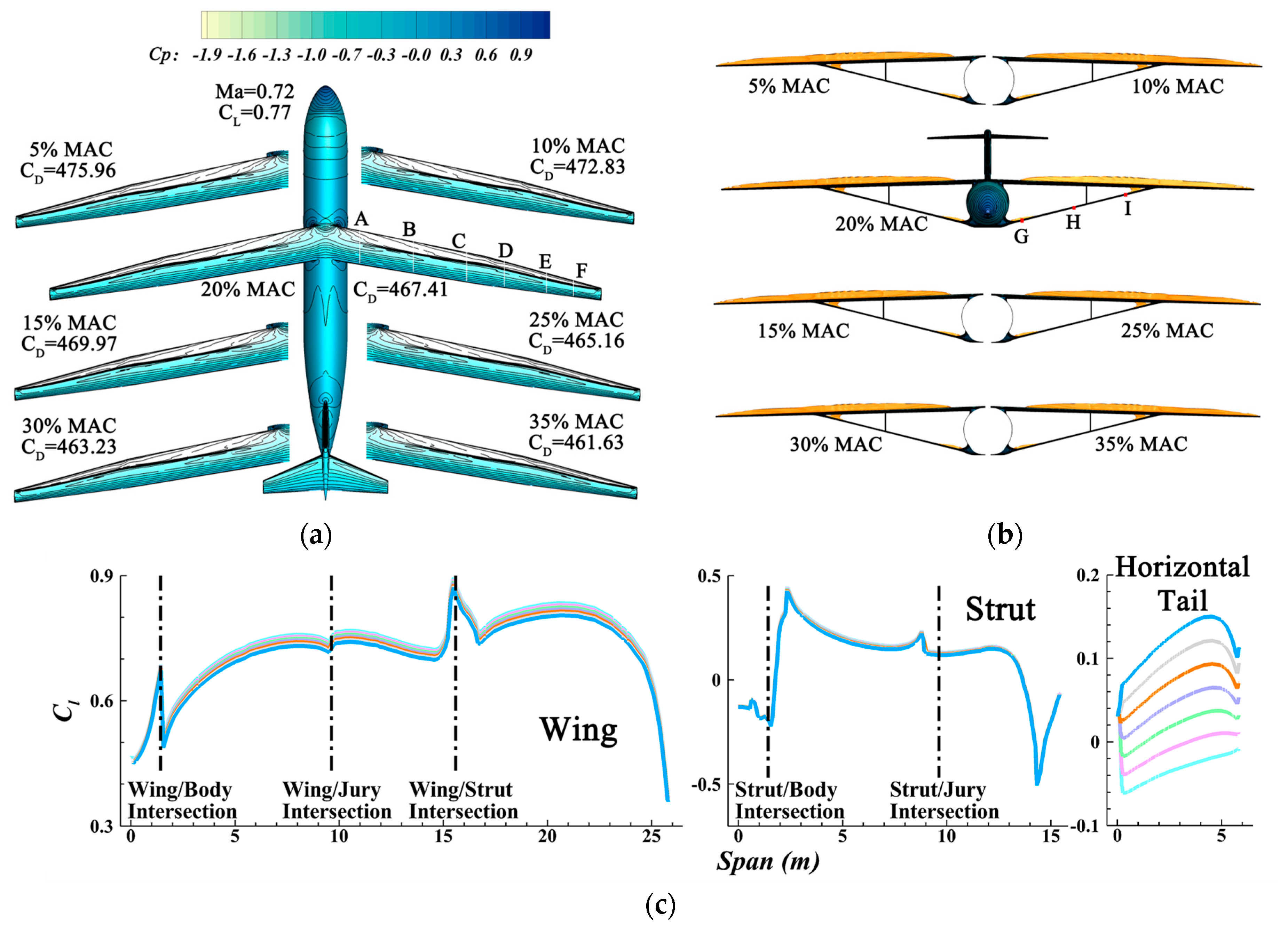
| M | CL | CG Location (% MAC) | CD (Counts) | ΔCD (%) |
|---|---|---|---|---|
| 0.72 | 0.770 | 5 | 475.96 | / |
| 10 | 472.83 | −0.66 | ||
| 15 | 469.97 | −1.26 | ||
| 20 | 467.41 | −1.80 | ||
| 25 | 465.16 | −2.27 | ||
| 30 | 463.23 | −2.67 | ||
| 35 | 461.63 | −3.01 | ||
| 0.70 | 1.001 | 5 | 693.91 | / |
| 10 | 686.72 | −1.04 | ||
| 15 | 679.92 | −2.02 | ||
| 20 | 673.57 | −2.93 | ||
| 25 | 667.76 | −3.77 | ||
| 30 | 662.51 | −4.53 | ||
| 35 | 657.56 | −5.24 |
| M | CL | CG Location (% MAC) | CD (Counts) | ΔCD (%) | Kn (%) | η (°) |
|---|---|---|---|---|---|---|
| 0.70 | 0.770 | 5 | 400.35 | / | 42.6 | −1.872 |
| 5_35% MAC | 397.75 | −0.65 | 12.6 | −0.072 | ||
| 10 | 398.99 | −0.34 | 37.5 | −1.615 | ||
| 15 | 397.46 | −0.72 | 32.5 | −1.344 | ||
| 20 | 395.96 | −1.10 | 27.5 | −1.103 | ||
| 25 | 394.69 | −1.41 | 22.5 | −0.849 | ||
| 30 | 393.14 | −1.80 | 17.4 | −0.595 | ||
| 35 | 391.84 | −2.13 | 12.3 | −0.366 |
| M | CL | CG Location (% MAC) | CD (Counts) | ΔCD (%) |
|---|---|---|---|---|
| 0.72 | 0.770 | 5 | 409.48 | / |
| 5_35% MAC | 405.74 | −0.91 | ||
| 10 | 407.13 | −0.57 | ||
| 15 | 405.59 | −0.95 | ||
| 20 | 404.24 | −1.28 | ||
| 25 | 402.86 | −1.62 | ||
| 30 | 401.34 | −1.99 | ||
| 35 | 399.58 | −2.42 | ||
| 0.70 | 1.001 | 5 | 491.65 | / |
| 5_35% MAC | 483.39 | −1.68 | ||
| 10 | 490.36 | −0.26 | ||
| 15 | 487.80 | −0.78 | ||
| 20 | 485.15 | −1.32 | ||
| 25 | 484.65 | −1.42 | ||
| 30 | 483.08 | −1.74 | ||
| 35 | 481.23 | −2.12 |
| M | 0.67 0.770 | 0.68 0.770 | 0.70 0.770 | 0.72 0.770 | 0.73 0.770 | 0.70 0.720 | 0.70 0.820 | 0.70 1.001 | |
| CL | |||||||||
| Ori | CD(counts) | 362.11 | 363.40 | 367.75 | 377.58 | 385.86 | 343.51 | 397.45 | 570.45 |
| M*L/D | 14.25 | 14.41 | 14.66 | 14.68 | 14.57 | 14.67 | 14.44 | 12.28 | |
| Opt | CD(counts) | 310.84 | 312.07 | 314.50 | 322.85 | 344.33 | 303.59 | 327.98 | 403.78 |
| ∆CD (%) | −14.16 | −14.12 | −14.48 | −14.49 | −10.76 | −11.62 | −17.48 | −29.22 | |
| M*L/D | 16.60 | 16.78 | 17.14 | 17.17 | 16.32 | 16.60 | 17.50 | 17.35 | |
| ∆M*L/D (%) | 16.49 | 16.45 | 16.93 | 16.95 | 12.06 | 13.15 | 21.18 | 41.28 |
Disclaimer/Publisher’s Note: The statements, opinions and data contained in all publications are solely those of the individual author(s) and contributor(s) and not of MDPI and/or the editor(s). MDPI and/or the editor(s) disclaim responsibility for any injury to people or property resulting from any ideas, methods, instructions or products referred to in the content. |
© 2023 by the authors. Licensee MDPI, Basel, Switzerland. This article is an open access article distributed under the terms and conditions of the Creative Commons Attribution (CC BY) license (https://creativecommons.org/licenses/by/4.0/).
Share and Cite
Li, L.; Qiao, L.; Xu, J.; Bai, J. Effects of Static Stability Margin on Aerodynamic Design Optimization of Truss-Braced Wing Aircraft. Aerospace 2023, 10, 603. https://doi.org/10.3390/aerospace10070603
Li L, Qiao L, Xu J, Bai J. Effects of Static Stability Margin on Aerodynamic Design Optimization of Truss-Braced Wing Aircraft. Aerospace. 2023; 10(7):603. https://doi.org/10.3390/aerospace10070603
Chicago/Turabian StyleLi, Li, Lei Qiao, Jiakuan Xu, and Junqiang Bai. 2023. "Effects of Static Stability Margin on Aerodynamic Design Optimization of Truss-Braced Wing Aircraft" Aerospace 10, no. 7: 603. https://doi.org/10.3390/aerospace10070603