1. Introduction
The development of various types of unmanned aerial vehicles (UAVs) has been determined by technological progress in the last two decades. UAVs mostly belong to the category of aerodynes, aircraft heavier than air which achieve motion in three-dimensional (3D) space by aerodynamic forces and moments created by the movement of the aircraft itself through the air or by moving (rotation) its parts. According to the way aerodynamic forces and moments are created, there are two basic classes, namely fixed-wing and rotary-wing aircraft. Fixed-wing UAVs are used most often in surveillance missions where it is necessary to cover longer distances, as shown in research [
1] which represents a low-cost fixed-wing system intended for lake shoreline investigation. Contrary to fixed-wing, rotary-wing UAVs are capable of vertical take-off and landing (VTOL) and stationary flight. The advantages of using rotary-wing aircraft lie in the fact that it does not need a launch pad, runway, or human intervention to perform the mission, and small size aircraft can take off from a limited area. Moreover, while mechanically controlled helicopters marked the beginning of the second half of the 20th century, the development of rotary-wing aircraft continued using fly-by-wire control. The most common configuration of a helicopter UAV is the main/tail rotor configuration, for which control and navigation techniques are shown in the paper [
2]. Currently, the development and production of miniature computers and control system components that have high processing speeds, enabled expansion in the research and applications of multirotor type of UAVs.
Numerous studies preceded the appearance of commercial multirotor aircraft such as Parrot AR.Drone which represents the so-called quadrotor configuration. The AR.Drone is one of the open source platforms that, in addition to commercial use, is very often used in research and education [
3]. The development of the system enabled a wide range of applications considering the multirotor type of UAVs characterized by high agility and maneuverability. Research has been conducted that deals with inspections of energy infrastructure, such as the wind turbine blade inspection using a quadrotor aircraft equipped with LiDAR [
4]. When inspecting the energy infrastructure, it is important to consider the possible specific conditions; therefore, in the paper [
5], navigation in the presence of a magnetic field was presented in the case of transmission line inspection. Furthermore, the quadrotor aircraft can be considered in applications that include delivery, transfer, or manipulation in the environment, such as an aircraft system equipped with a multidegree of freedom manipulators [
6]. The multirotor type of UAV is applicable in the field of aerial robotics, considering that depending on the number of rotors and configuration parameters, it is possible to perform missions that involve interaction with the environment or require precise movements [
7]. It is important to note that configurations with more than four rotors, such as configurations with six, or eight rotors, are more resilient to propulsion failure. Furthermore, the development of electric propulsion components with precise and fast control and batteries of high specific energy density has further enhanced the applicability of multirotor aircraft in cargo transfer applications or missions involving the dispersal of payload contents. Currently, such missions are typical in the field of smart agriculture, where besides common tasks that include mapping, missions consist of spraying, fertilizing, or sowing.
Although missions involving payload dispersal from the air are not new, the application of aircraft, such as PZL-Mielec M-18 Dromader [
8], or PZL-106 Kruk [
9] is limited because compared with conventional land-based systems it consumes much more energy. Additional infrastructure is also needed because this type of aircraft requires a runway. Since manned missions include pilots and such systems need complex maintenance, these make the operation more expensive, so they are not used on a larger scale. They are mainly used for spreading fertilizers or for spraying tasks on flat plots with large areas. Continuous demands for sustainable agricultural production have led modern farmers to use UAVs of various types, configurations, and sizes. The trends and applications of UAVs in agricultural missions, related equipment, and control technologies, are shown in the paper [
10]. Multirotor UAVs were considered in many applications, such as biomass estimation in rice crops using multispectral imagery [
11]. On the other hand, multirotor UAVs have been investigated for applications involving payload dispersal for aircraft of different sizes that can carry different payloads. In papers [
12,
13], small UAVs retrofitted with a spraying system in order to execute spraying tasks are shown. In the case of UAV spraying for peach trees protection [
12], the following physical and flight parameters were considered: tank capacity 12 L, flow rate 1.5–3 L/min, spraying width 4 m, flight velocity 2–5 m/s, flight height 2 m, flight duration 30 min, and others. The spraying task is crucial from the aspect of mission performance, and in the work [
14], was provided a comparison of a six-rotor UAV, a boom sprayer, and two conventional backpack sprayers for wheat crops droplet deposition. The considered mission and UAV have the following parameters: tank capacity 5 L, flow rate 1.24 L/min, spraying width 4 m, flight velocity 3.5–4 m/s, flight height 1 m, and flight duration 15–20 min. To achieve desired droplet deposition the optimal flying speeds, and spraying rate of market standard systems were evaluated in [
15], where the typical parameters of the aircraft and the mission are comparable to the parameters in papers [
12,
14]. The types of missions to which multirotor aircraft can be applied in the field of precision agriculture are smaller application areas of up to several hectares. One of the advantages is that multirotor aircraft can be used on uneven terrain, or in extreme cases, inaccessible terrain for land-based vehicles. This type of system is also suitable when there are small, fragmented plots. One of the potential applications is in fish farming for supplementary feeding. Regardless of whether the purpose is mapping or, for example, sowing, one of the main challenges is to determine flight parameters and flight routes in order to achieve sustainable pest control. Uniform distribution and optimal consumption of pesticides are important; therefore, in research [
16], a neural network algorithm was employed to obtain an optimal pesticide spraying route. Given that variable weather conditions play a significant role in spraying tasks, the use of a genetic algorithm for autonomous route adaptation was proposed in the paper [
17].
Of the commercial solutions that are intended for applications in precision agriculture with a heavy payload, the largest market share is reserved by the DJI Agras series of multirotor aircraft [
18]. The flagship UAV of the Agras series, DJI T40 [
19] can be applied for spraying and spreading tasks. According to information from the official website, hovering time without payload is 18 min for aircraft take-off weight of 50 kg equipped with a 30,000 mAh battery. The main flight parameters in the case of farmland spraying are: a consumption rate of 15 L/ha, spray width of 11 m, a flight speed of 7 m/s, and flight altitude of 3 m, while in the case of orchards spraying: a consumption rate of 75 L/ha, spray width 4 m, flight speed 3 m/s, and flight altitude 2 m. Take-off weight with full payload is 90 kg, and hovering and spraying time with full payload is 7 min. Flight parameters in case of spreading fertilizer: consumption rate 149 kg/ha, spread width 7 m, flight speed 7 m/s, flight altitude 3 m, spreading disc rotation speed 1000 RPM at which take-off weight with full payload is 101 kg, and spread tank internal load is 50 kg which consists of solid dry particles with a diameter of 0.5 to 5 mm, where spread width is 7 m. Some smaller companies on the market produce small series of aircraft such as the Agronator [
20] multirotor. The sowing rate advice for wheat is approximately 150 to 200 kg/ha. Thus, with the considered load of 50 kg, wheat can be sown in a field of approximately a quarter of a hectare in one take. Mostly remotely controlled or semi-autonomous systems are in use. After searching the literature and commercial solutions, we found that there are not many multirotor platforms for large payloads up to 50 kg, but there are concepts and platforms that are used in the field of cargo transportation.
A survey on multirotor UAVs intended for load transportation was presented in the paper [
21], taking into account two basic approaches, namely grasped and cable-suspended (swing) transportation. For missions in the field of precision agriculture, the cargo is mounted on the body of the aircraft, and the important fact is that the mass of the cargo is variable (it decreases as the mission progresses). In the field of heavy cargo transport or applications involving large-scale payload, compared with conventional UAV applications there are fewer works and commercial solutions. This stems in part from the fact that components are more expensive and due to the large size of the UAV, it is more complex to ensure space and experimental setup to safely conduct experiments. In addition to aircraft equipped with conventional electric propulsion units, other versions of the propulsion system were investigated in the area of heavy lift payload. The paper [
22] presented mathematical modeling and control of quadrotor UAV equipped with ICE motors in combination with fixed pitch propellers and the concept of moving mass control. In contrast to the research of hardware and software solutions, the use of aircraft for deliveries in terms of technologies, market, regulations, and impact on society is taken into account in the research [
23]. As for commercial solutions, as already mentioned, the platforms used for heavy lift are mostly produced in smaller series and are also produced by smaller companies such as Drone Volt [
24] and Harris Aerial [
25]. To the best of our knowledge and with a search of the literature papers or commercial solutions, designs of modular systems capable of carrying heavy loads were not found.
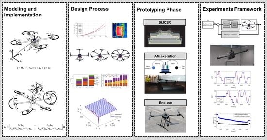
This paper presents the modeling and design of the novel concept of a modular aerial robotic platform which can be assembled for specific mission profiles including a variety of heavy load tasks. From the aspect of system modeling, a comprehensive mathematical description of the multirotor UAV model is presented that includes the description of aircraft configurations with different parameters and characteristics. The derived model is implemented in a software package for the purposes of performing simulations and control system design. The first contribution of this research is a systematic overview of the design procedure for heavy lift multirotor UAV configurations, which consists of the characterization of the propulsion and energy module with various parameters and components. The second contribution is the novel concept of a modular multirotor UAV platform, consisting of four easy assembly modules, capable of performing tasks in the field of logistics and precision agriculture. Given that the main goal is to design a modular platform, considered fields are in a certain range of sizes (approximately from 103 up to 105 m2), and according to the current state of the art in precision agriculture. The advantages of the modular platform lie in the fact that the configuration parameters can be changed for a specific setup, so with the same aircraft it is possible to perform a wider range of tasks that include the transport or dispersion of cargo, such as spraying, fertilizing, or sowing. The results of simulations of typical mission profiles with different aircraft configurations, both underactuated and fully actuated, are shown. A quadrotor configuration was prototyped, for which preliminary experimental tests in the cases of attitude and remote control are provided. Another advantage of the proposed robotic platform is the possibility of integration with a base station that can be mobile and can be delivered to the application area. This is made possible by modules that enable simple pre-assembly, and especially the potential for automated battery replacement. The integration of the UAV and the base station significantly increases the autonomy of the robotic system and reduces mission costs. Such a system can potentially replace current operations that involve a large effort in the operator’s time and are therefore more expensive.
2. Mathematical Representation of Multirotor UAV
Due to its nature, the multirotor type of UAVs represents extremely non-linear systems, which results from several facts. The two most important ones are that trigonometric functions appear during the transformation of coordinate systems and that the aerodynamic effects of the propulsion units are non-linear functions of the rotors angular velocities. In contrast to a fixed-wing UAV, which can be directly remotely controlled, given that the control variables are related to the thrust force and flight control surfaces (aileron, elevator, and rudder), a multirotor type of UAV is inherently unstable, and a control algorithm is required for system operation. If the functionality of the control loops is lost, this type of aircraft cannot return to equilibrium, the hovering state; therefore, the aircraft starts to move uncontrollably and eventually falls. Multirotor UAVs are multivariable systems, they have six degrees of freedom (DOF), 12 state variables, given that they operate in 3D space, and the propulsion configuration consists of N controlled rotors. Since they have six DOF, they are described by six second-order differential equations, where aircraft can be defined as a rigid body where only moving parts are rotors of the propulsion configuration.
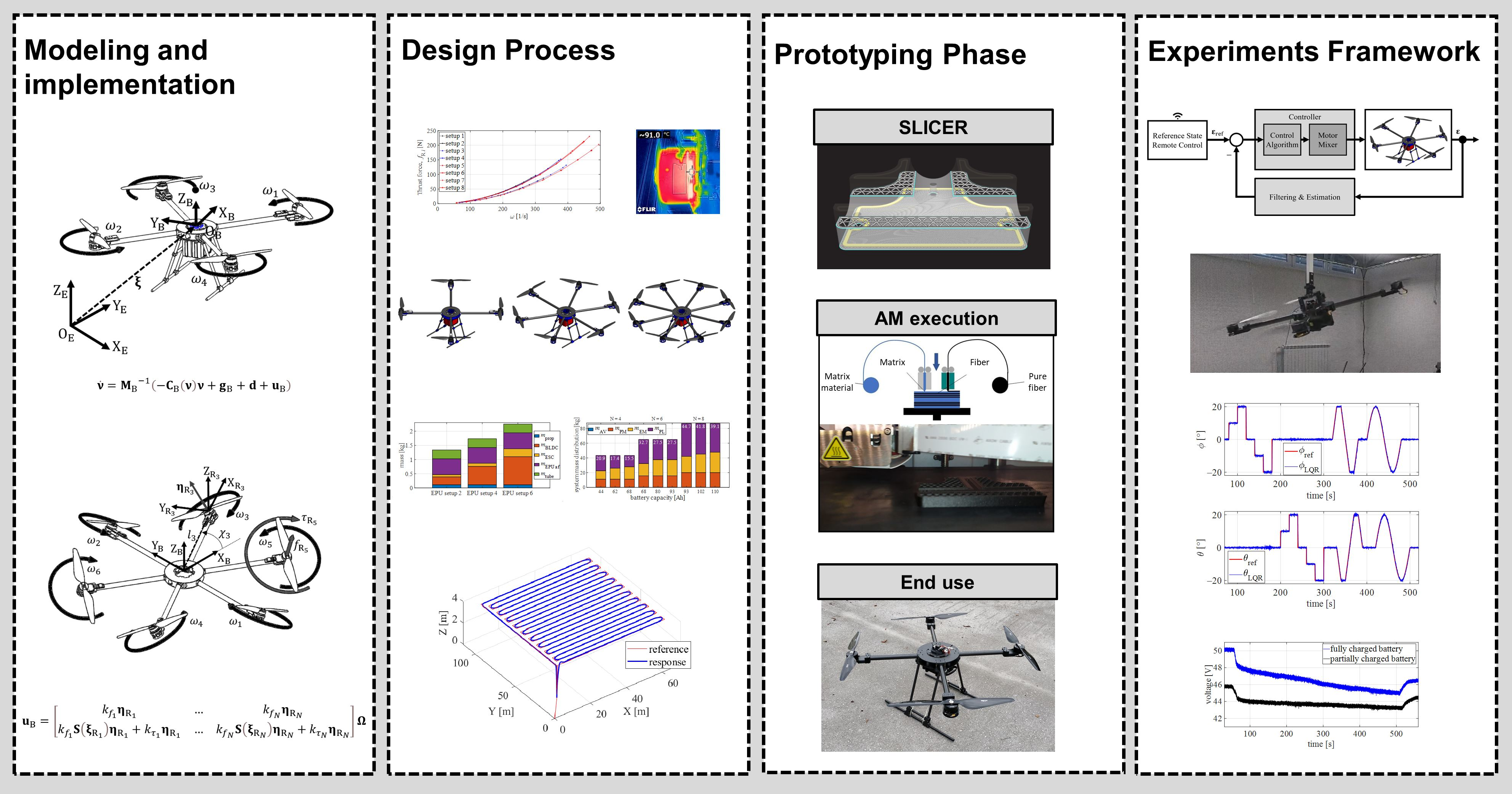
For the purpose of a mathematical description of the multirotor UAV, two right-handed Cartesian reference coordinate systems are defined. The mission of the aircraft can be represented by the reference state in relation to the initial coordinates, i.e., the starting point of the mission. At that point, which is fixed on the ground, for example, a base (docking) station, an inertial coordinate system is attached, which is also called the earth frame (
). It consists of the origin and three axes
, the longitudinal (
), lateral (
), and vertical (
) axis that is perpendicular to the ground and in which the gravitational force acts. Two representations are commonly used, the so-called north-east down (NED), or east-north up (ENU), which is used further in this paper. In relation to the earth frame, the position of the aircraft is defined by three coordinates
and the orientation of the aircraft is defined by three angles
, where
is roll angle,
is pitch angle, and
is yaw angle. A reference state is defined in the earth frame, which can be represented by a reference trajectory, or for example, with waypoints, depending on what the mission is. The following coordinate system is fixed in the body of the aircraft, so it is often called the body frame (
) and is defined by the origin and the axes
. It is defined for practical reasons, considering that flight controller (FC) inertial sensors measurements are related to the aircraft body which moves in 3D space, and with the observation that the propulsion control forces and moments are also related to the aircraft body. To simplify the model, it is assumed that the origin of the body frame coincides with the aircraft’s center of gravity (CoG) and that the body frame axes coincide with the multirotor main axes of inertia. The reference coordinate systems are shown in
Figure 1.
2.1. UAV Kinematics
Assuming that the multirotor UAV is a rigid body, the motion of the aircraft can be described by the translation and rotation of a particle located at the CoG. It follows that the translational motion of a rigid body with 6 DOF can be described by the following expression:
where
is the translational velocity vector of the aircraft with respect to the body frame. The rotation matrix
maps the velocities by complex rotation over the fundamental rotation matrices (
), in the order yaw-pitch-roll, as shown in [
26], and is provided by the following expression:
where
,
.
Rotational motion of a rigid body can be described by the following expression:
where
is the rotational velocity vector of the aircraft with respect to the body frame. Since the rotational velocities occur around a particular axis, the mapping from the body frame to the inertial frame goes through a complex transformation matrix provided by the following expression:
where
.
Therefore, overall kinematics is described by the following equation:
where
is the velocity vector with respect to the earth frame through which the position and orientation of the aircraft
is obtained, and the velocity vector
is the velocity vector with respect to the body frame which results from the dynamics of the aircraft. When implementing the mathematical model, we can observe it block-wise, where the velocity vector of the aircraft
is the input of the kinematics block (5), and the position and orientation vector, which is the output, is obtained using an integrator for each DOF.
2.2. Multirotor UAV Dynamic Model
The equations of motion are represented by six second-order differential equations, one for each degree of freedom, using the Newton–Euler method [
27]. Following the kinematic model, the equations of motion are divided into translational (linear) and rotational motion of a rigid body. The equation of translational motion based on Euler’s 1st law is provided by the following equation:
where
is the vector of forces acting on the body with respect to body frame. The mass of the aircraft
, consists of system components, airframe parts, and the payload. Considering a heavy lift multirotor aircraft that can be used in precision agriculture or logistics, the mass of the cargo can be variable
). Mass is a key parameter from the aspect of system design.
The equation of rotational motion based on Euler’s 2nd law is provided by the equation:
where
is the vector of moments acting on the body with respect to body frame. The body’s inertia tensor
, under the assumption that the body of the aircraft is symmetrical with respect to the main axes of inertia, becomes the diagonal matrix
.
It follows that the equations of motion can be defined by the following equation:
On the left side of Equation (8), the first matrix
contains mass and moments of inertia, while the second represents the Coriolis and the centripetal matrix
[
28]. On the right side of the equation are forces and moments
that affect the dynamics of the aircraft, which is provided by the following equation:
The gravitational force vector
, defined with respect to the body frame, acts on the translational dynamics. Unmodeled dynamics such as gyroscopic moment or air resistance and external disturbances such as wind gusts are contained in the disturbance vector .
Given that the only moving parts of a multirotor aircraft are the rotors with mounted propellers, the forces
, and moments
of the propulsion system required to move the aircraft in 3D space, form the control vector
, which is defined by the following equation:
The configuration of the aircraft and the characteristics of the propulsion units are contained in the control allocation scheme, where the matrix maps the input variables of the model, which are represented by a vector containing the angular velocities of each rotor . The dynamics block represents a function that solves differential Equation (9), where standard or custom-solving methods can be used. The input of the dynamics block is the control vector, and the block is defined by aircraft parameters that depend on the mass and layout of the aircraft assembly. This block also has an unknown disturbance vector acting on the system.
2.3. Multirotor UAV Control Allocation Scheme
The configuration of the aircraft is determined by the parameters of the propulsion system, which consists of
N rotors. Conventional multirotor configurations consist of an even number of identical rotors symmetrically arranged in one or more parallel planes. Each pair consists of CW and CCW rotors to cancel the reactive moment about the vertical axis of the aircraft. The most used configuration has four rotors, the so-called quadrotor (quadcopter). In this version, the rotors are located in one plane at the ends of the diagonals, which are placed in X or + configuration in relation to the
axis of the body frame. Apart from the quadrotor, configurations with six rotors, the so-called hexarotor (hexacopter) [
29] or eight rotors, the so-called octorotor (octocopter) [
30], which have a higher payload, are often used. In this paper, a comprehensive (more general) approach to defining the control allocation scheme was considered, which also includes non-planar configurations where the axes of the rotors are no longer parallel to the
axis.
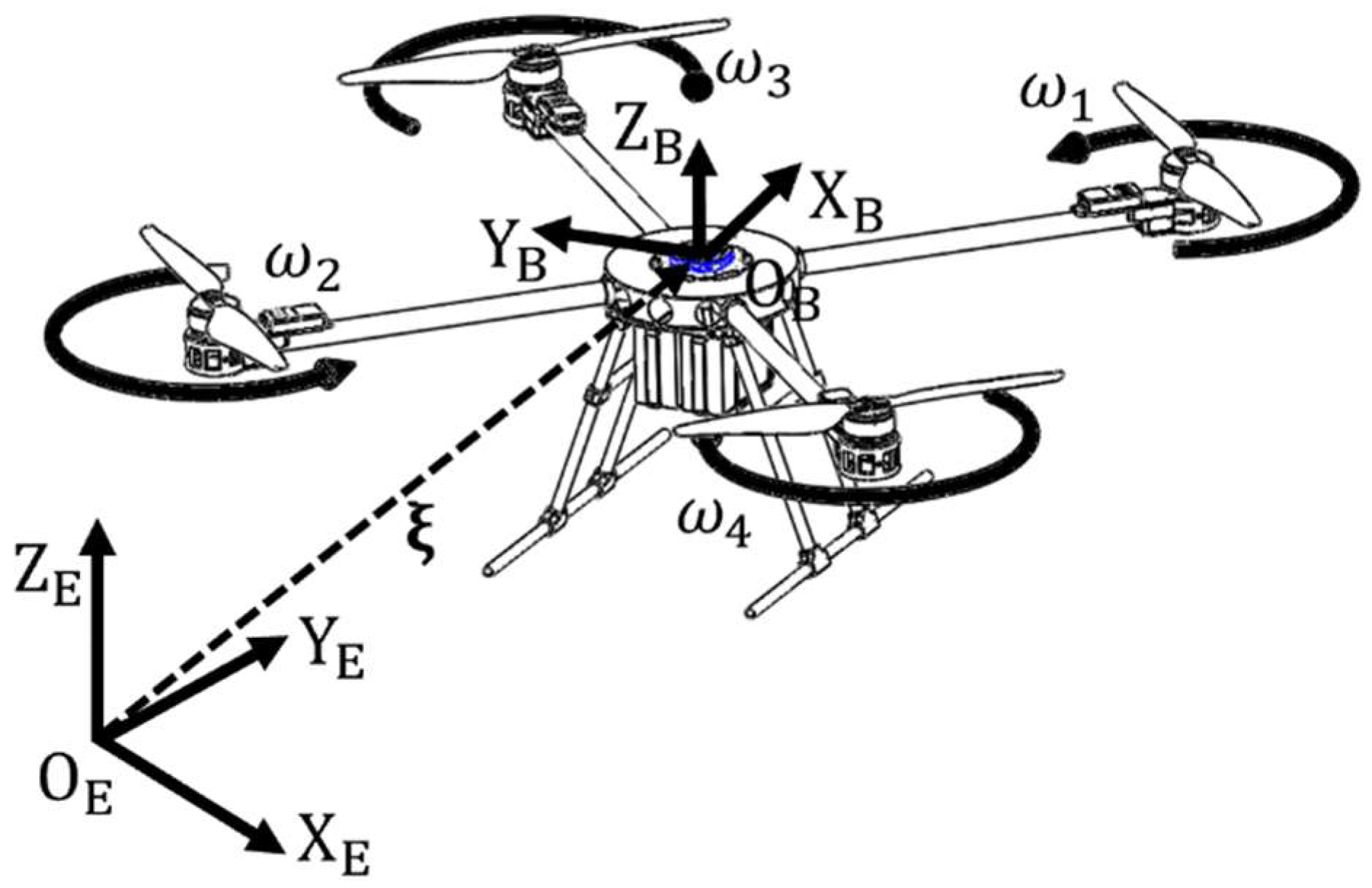
Figure 2 shows the configuration of the aircraft with the corresponding reference coordinate systems. Given that configurations with different parameters of the rotor’s geometric arrangement are considered through the design and simulation phases, a schematic configuration with passively tilted rotor arms is shown to describe the generic configuration model that is in the scope of this research.
For each rotor, it is necessary to define the right-handed rotor coordinate system (
), which determines the position and orientation of the rotor in relation to body frame. The axis of the rotor arm, which connects the origin of the aircraft system and the rotor system, is marked with
and has a positive direction from
to
. The vertical axis
has the same orientation and direction as
. The position of the
i-th rotor
is basically defined by two parameters: the length of the rotor arm
and the angle (
) between the axis
and
. These are also the basic parameters of conventional configurations. Furthermore, for the considered modular configuration, the assumption that the rotors are located on the
plane is introduced, and the height of the rotor placement is ignored, which simplifies the model. The position vector of the
i-th rotor is provided by the following equation:
Aerodynamic forces and moments are represented in the axis of the rotor. In planar configurations, the rotor axes and the
axis of the body frame are parallel, so the orientation vector is equal to the unit vector
. In multirotor configurations with non-planar rotors, the rotor orientation parameters, dihedral angles, and tilt angles are introduced into the model. These parameters determine the distribution of aerodynamic forces and moments of individual rotors on the aircraft control vector. The dihedral angle of the
i-th rotor
defines the elementary rotation matrix around the
axis, and the tilt angle of the
i-th rotor
defines the elementary rotation matrix around the
axis of the rotor arm. The orientation vector of the
i-th rotor is provided by the following equation:
Configuration geometric arrangement, which describes the mapping of aerodynamic forces and moments to the control vector is provided by a matrix containing the orientations of individual rotors:
where a matrix
that is made of vector products of position and orientation for mapping thrust force and drag torque to control moments. The matrix is derived using the matrix representation of the vector product
and is provided by the following expression:
By deriving the previous matrices, it is possible to map aerodynamic effects caused by the rotation of the rotor’s propeller to the control vector. The assumption is that the effects consist of the rotor thrust force and the drag torque . The characteristics of thrust force and drag torque depend on the selected propulsion components. Manufacturers provide specifications from which propulsion unit characteristics can be derived. For a more detailed and precise insight, it is necessary to conduct experimental measurements. Conventional multirotor propulsion systems are fabricated of identical electric propulsion units (EPUs) consisting of a brushless DC (BLDC) motor with associated electronic speed controller (ESC), and fixed pitch propellers mounted on the motor rotors, which generate aerodynamic forces and moments.
For the purpose of performing simulations, the characteristics can be presented as functions, while in the implementation phase of the aircraft control they are mostly linearized in relation to the control PWM signal. Furthermore, a model is used where the aerodynamic effects are proportional to the square of the angular velocities [
26]. In this case, the thrust force of the
i-th rotor is provided with following equation:
where
is the angular speed of the
i-th rotor, and
is the thrust force factor that depends on the propeller geometry and air density, as well as the potential interference of the airflow. The drag torque of the
i-th rotor is equal to
where
is the drag torque factor of the
i-th rotor which depends on the propeller geometry, air density, motor power, and potentially on interference. Therefore, input is defined as vector of the square of the angular velocities
.
Based on the presented
and
matrices and expressions for aerodynamic effects, the decomposed matrix form of the control allocation scheme is provided with the following expression:
The EPU parameters are represented by a diagonal matrix consisting of rotor thrust force factors , and diagonal matrix of drag torque factors . The sign of the drag torque factor depends on the direction of rotation, where CW rotors have a positive sign, while CCW rotors have a negative one.
As a result of the fact that in conventional configurations the thrust vector of an individual rotor is parallel to the vertical axis of the body frame, the matrix rank is not of full order. Such configurations, regardless of the number of rotors, represent an underactuated system. This information is very important from the aspect of flight planning, given that the dynamics of such systems are coupled. It is clear from Equation (17) that in order to achieve the full rank of the matrix, it is necessary to select the orientation parameters of the propulsion units. Fully actuated passively tilted rotor configurations have been investigated mainly for six [
31] and eight [
32] rotors, where the rotor tilt angle is a key parameter and changing it is not possible in flight.
From the point of view of the mathematical model, the block of the control allocation scheme maps the input variables of the propulsion module (angular velocities of the rotor) to the output control vector and is defined by the parameters of configuration geometric arrangement, and the characteristics of the propulsion units. With this approach, it is possible to carry out simulations for conventional configurations as well as configurations with a non-planar arrangement of rotors such as the configurations investigated in papers [
31,
32,
33]. When implementing the control of a multirotor aircraft, it is necessary to allocate the control variables coming from the control algorithm to the signals sent to the EPUs. In existing software solutions for conventional aircraft configurations, there are linearized and scaled forms of the inverse of the allocation scheme. Given that configurations can have less or more than six rotors, one way to solve the problem is by using the pseudoinverse provided by the expression:
3. The Process of Designing an Aerial Robotic Platform for Heavy Lift Payloads
In addition to the standard versions of UAVs, so-called reconfigurable UAVs are being investigated such as the platform presented in the research [
34,
35]. According to a literature survey [
36], three categories of reconfigurable multirotor UAVs can be distinguished: tiltrotor UAV with multidirectional capabilities, multi-modal multirotor that can move on land or in water in addition to flying, and foldable UAV that can be converted into different geometries in flight. There are different approaches to the design of UAV systems, such as the modular approach [
37], and regarding multirotor UAVs, the modular architecture is presented in research [
38]. Such an approach can be used in the case when a task typically requires an aircraft with a particular physical architecture.
The main goal is to design a modular reconfigurable aerial platform that can perform missions with a wider range of payloads. Designing a multirotor UAV (especially in the case of carrying heavy payloads) is a very challenging problem since this type of UAV is characterized as a high-energy consumption aircraft. Given that it is a multirotor type of unmanned aircraft, the term heavy payload (lift) is usually used in the literature for aircraft that can carry loads of up to 50 kg, which is indicated in [
22,
24,
39,
40,
41,
42].
The performance of such a system depends on the selected parameters and components concerning the mission requirements with regard to design constraints such as aircraft size. At the conceptual design stage, the division of the multirotor system into four key subsystems, i.e., modules, greatly facilitates the aircraft design, as well as the system assembly. The module consisting of equipment and payload depends primarily on the mission, where the main parameter is the mass . In the case of applications, such as sowing, the equipment in addition to the landing gear represents a tank, a spreading mechanism with a known mass, while the mass of the load (cargo) represents the seeds that are applied to a specific plot; therefore, cargo mass is variable. Depending on the mission requirements, it is necessary to select the parameters of the propulsion and energy module with the corresponding components. That process is complex since the propulsion module and energy module are interdependent. It is important to take efficiency into account when designing the system. Higher battery capacity consequently increases the mass of the system, so more power is needed to propel the aircraft.
The propulsion module except for the mass
can be defined on the other hand with the parameters of the geometric arrangement of the aircraft configuration and the characteristics of the selected propulsion components. The energy module is primarily defined by the number of batteries and their capacity and mass, which form the largest share of
. The mass of the individual modules that form the total mass of the aircraft is provided as:
where
is the control module (avionics) mass, which has the smallest share and can be neglected for heavy lift aircraft. The mission determined the required agility of the aircraft to be able to perform the required movements in 3D space. In the initial phase, agility is reduced to the so-called thrust-to-weight ratio (TWR), from which the take-off mass of the aircraft can be related to propulsion module maximum thrust force in the vertical axis (
). Component manufacturers for individual setups recommend take-off mass from which can be obtained and recommended TWR as a guide when designing the aircraft. Depending on the configuration of the aircraft which determines
, the aircraft take-off mass can be determined by the following expression:
3.1. Propulsion Module Characterization
In the development phase of the modular aircraft, the main goal is to design a propulsion module that allows the assembly of as many aircraft configurations as possible, while maintaining simplicity. The proposed novel modular heavy lift aerial platform consists of a propulsion module with a central assembly to which other aircraft modules and rotor arms are connected. The designed central assembly of the propulsion module enables the mechanical and electrical (energy and information distribution) connection. The propulsion module actually defines the multirotor configuration, whereby conventional (planar) and configurations with a non-planar arrangement of rotors are further considered. The size of the aircraft can be represented by the diameter (
), which is defined by the length of the rotor arms
. The aircraft diameter depends on the geometric arrangement and the number of EPUs (
) and the diameter of the propeller. Airframe design for configurations with four, six, or eight arms connected to a center assembly is considered. An additional feature is the possibility of assembling coaxial configurations, where it is important to examine the efficiency of such configurations considering that there are losses due to airflow interference, as shown by research [
43]. In extension to coaxial configurations, losses also exist in configurations that have overlapping rotor interference [
44], wherein [
45], the influence of propeller overlap for heavy lift propulsion is shown.
To simplify the assembly of modules, and reduce costs, rotor arms of the same length were designed for all considered aircraft configurations. The diameter of the proposed modular aircraft of 2 m allows the assembly of configurations without overlapping, for example, an octorotor UAV with EPUs consisting of 30-inch propellers, and hexarotor and quadrotor UAVs with 32-inch propellers. The main features of the novel multirotor UAV platform for heavy payload missions are related to the propulsion module, whereby the investigated configurations are with a payload mass range of 5 to 50 kg. In terms of required energy, the heavy lift propulsion module is paired with a high-voltage (HV) energy module composed of 12-cell (12S) Lithium polymer (LiPo) batteries. Based on the manufacturer’s specifications, EPU setups consisting of the Tiger motor components were selected. As the central part of the EPU is a BLDC motor, three motors were considered, AG1005, P80, and U13, which are the setups shown in
Table 1.
For the purposes of platform design, more detailed characteristics of the propulsion system were obtained by conducting experimental tests. For EPU characterization, experimental measurements were performed utilizing RCbenchmark 1780 with the appropriate software package for data acquisition. The experimental setup consists of a mechanical assembly with load cell sensors that are in charge of measuring mechanical quantities, i.e., aerodynamic forces (
) and torques (
). RPM was measured using an optical sensor that counts revolutions by detecting a marker mounted on the rotor. Furthermore, electrical quantities, battery voltage (
), and electric current (
) were also measured. The test consists of a series of measurements for considered setups, where for each setup, three measurement cycles are performed, first with an initial battery cell voltage of 4.2 V, then 4.0 V, and third with 3.8 V. The acquisition script was modified to take four measurements for each PWM value within one cycle and to store data in .csv format. Generated .csv files were loaded, processed, and graphically presented as EPU maps using a customized MATLAB script presented in previous research [
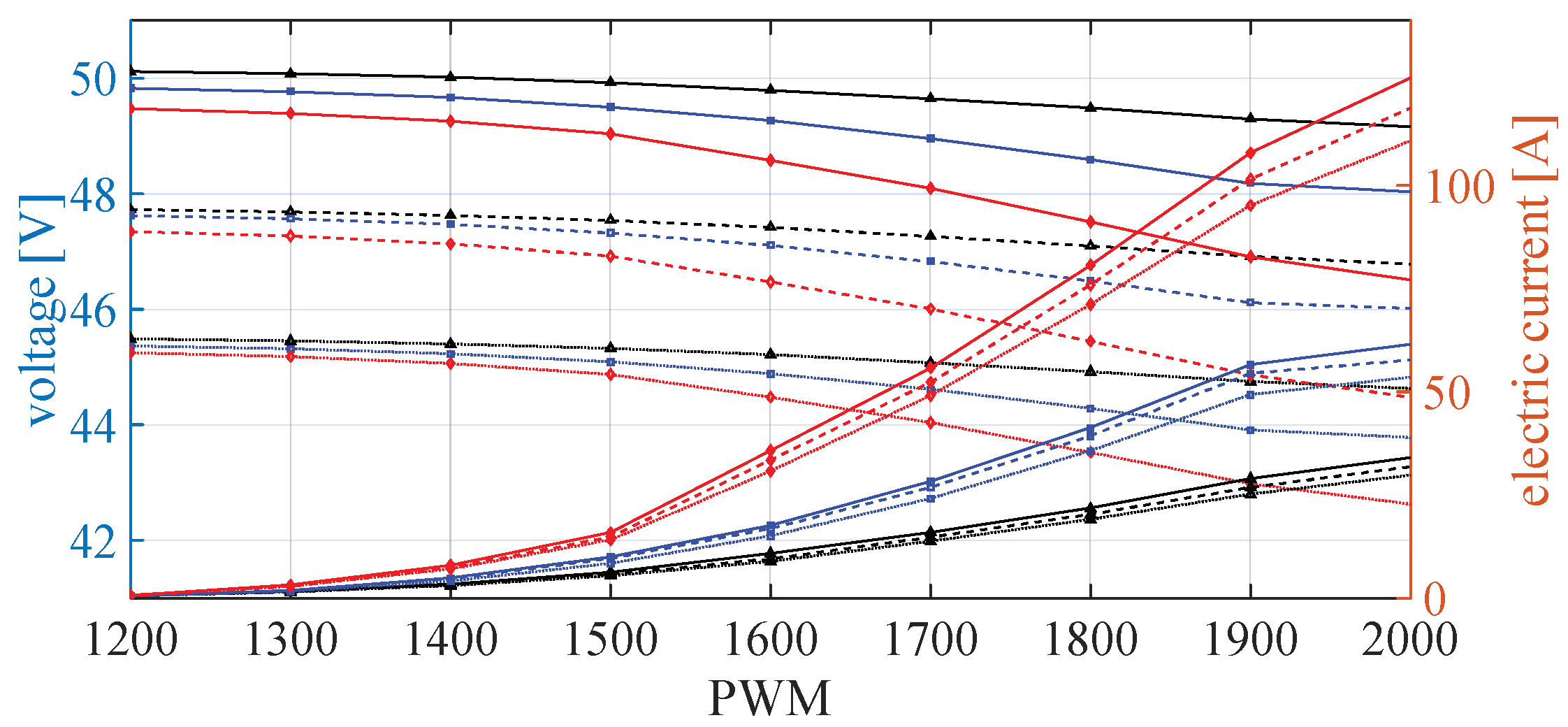
47]. Static maps represent the identified parameters as a function of the control PWM signal. Through the measurements, maps of thrust force, drag torque, RPM, battery voltage, electric current, and power were obtained. As for energy consumption, for a more precise estimation of the flight time, it is necessary to take into account the drop in battery voltage, since the consequence is an increase in current for the same performance, and therefore the battery discharges faster. Battery voltage drop and electric current drop with regard to PWM are shown in
Figure 3 for three setups at three levels of battery charge before the start of the measurement cycle.
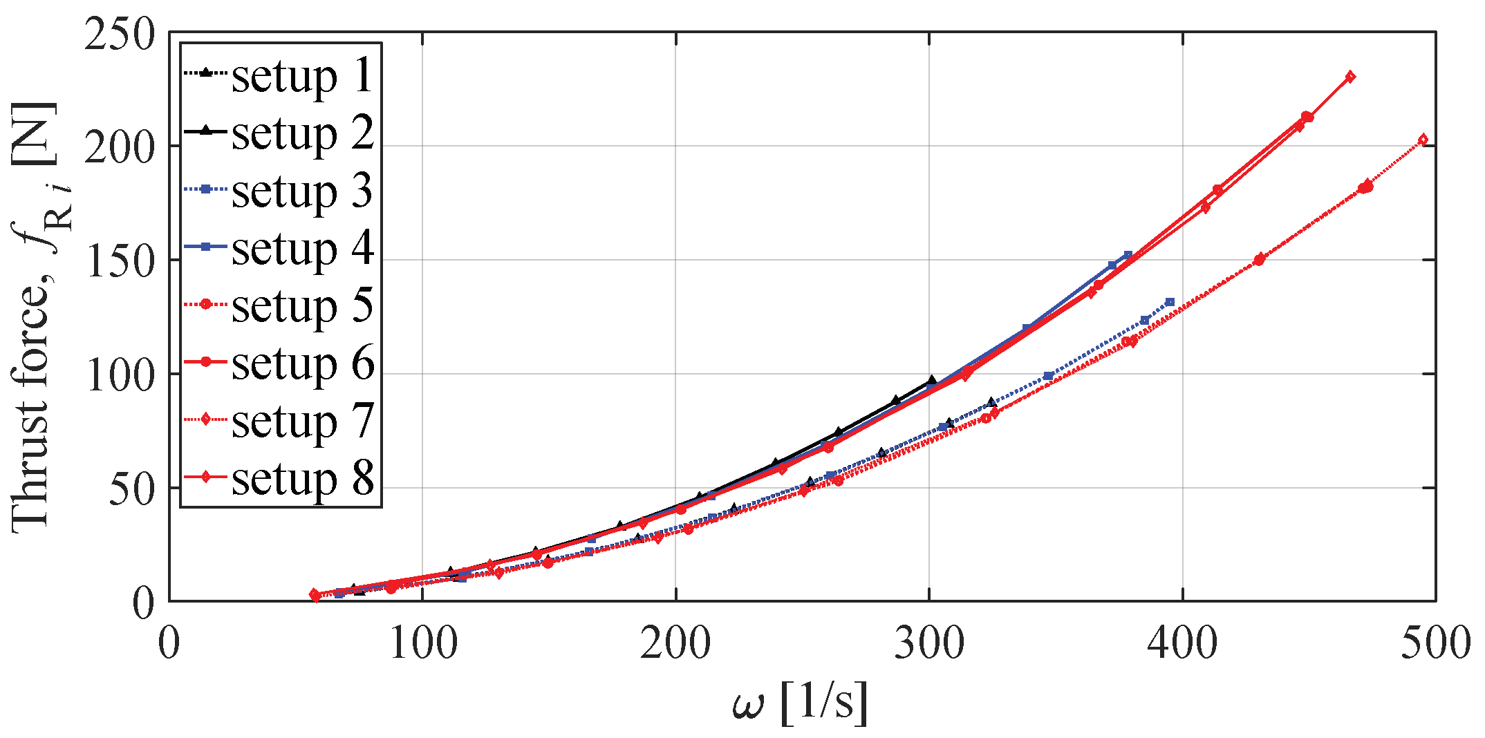
Based on the identified parameters of the EPU, a characterization is presented that is further used in the performance analysis of the electric propulsion system and can also be a starting point for optimizing the parameters of the aircraft configuration. Measurements taken using a battery with an initial voltage of 4 V/cell are used for further analysis. According to the considered model, the aerodynamic effects, the thrust force and drag torque of the rotor were defined, depending on the angular speed of the rotor. Thrust forces and drag torques for eight considered setups are shown in
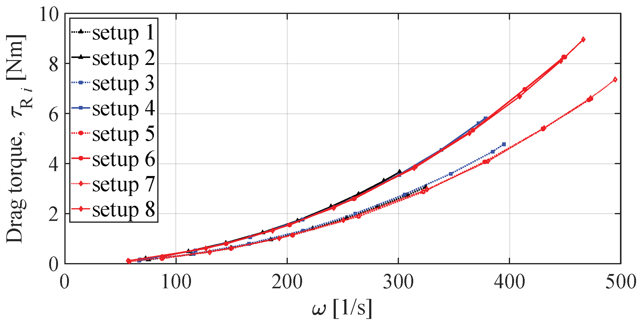
Figure 4 and
Figure 5, from which it is evident that the characteristics of the EPU depend primarily on the propeller diameter. The constant of the BLDC motor determines the angular speed of the rotor. To drive a propeller of a certain diameter, motors with a higher motor constant must have a higher torque to be able to produce higher thrust forces. A higher torque required to overcome the drag torque also means an increase in power (energy) consumption.
The thrust force depending on the angular speed of the rotor was approximated by the second-order curve using polyfit function, and is provided with:
The coefficients of the thrust force curve for six setups are shown in
Table 2.
The drag torque characteristic is also approximated by the second-order curve, and is provided with:
The coefficients of the drag torque curve shown in
Table 3.
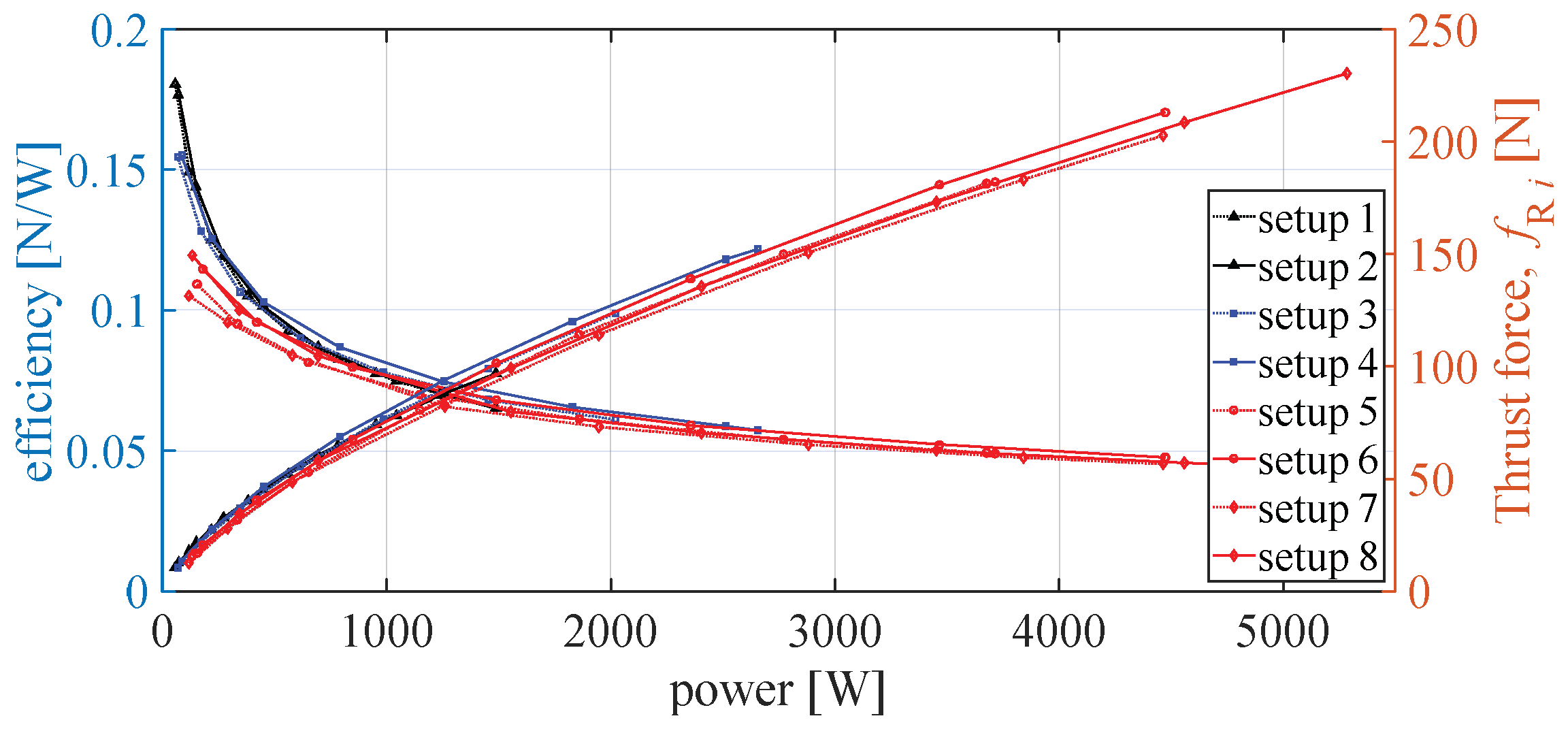
In the phase of designing the aircraft, it is necessary to select the components of the propulsion units, where efficiency is a key parameter.
Figure 6 shows the efficiency of the considered EPU setups in relation to power and thrust force, which is crucial in the design of the propulsion system.
From the presented characteristic, it is possible to show the relationship between the thrust force and the power of the propulsion unit. In this case, the second-order curve approximation was also used, and the expression for the thrust force was presented:
The coefficients of the thrust force curve related to power are shown in
Table 4.
In the design phase, the relationship between thrust force and power is crucial, and it needs to be analyzed and further used to optimize the configuration parameters.
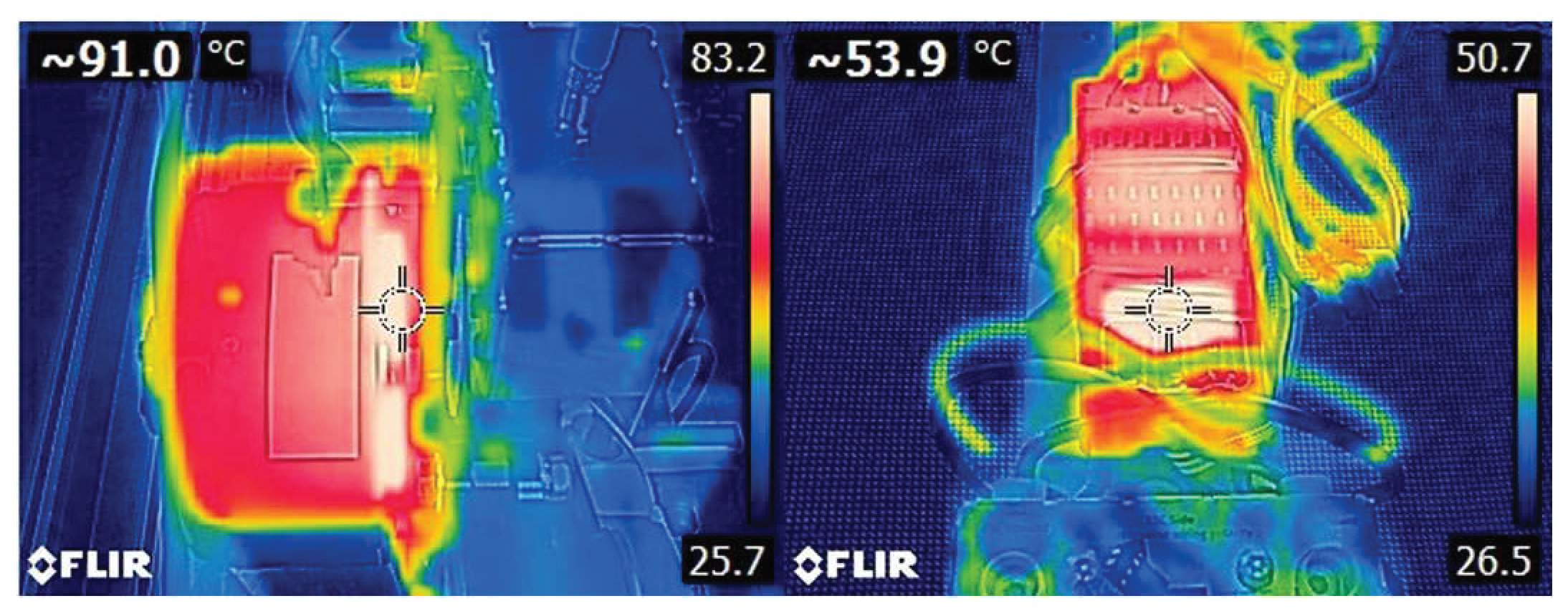
In addition to the mechanical characteristics of the EPU, it is also important to pay attention to potential heating spots from the aspect of structural integrity as it is necessary to design frame parts for high-power EPUs. The temperature of the BLDC motor and ESC was checked during and after each experimental measurement cycle of each setup. The considered ESCs come with an integrated passive cooler, and the measured temperatures are in accordance with the manufacturer’s specifications. BLDC motors heat up to higher temperatures and are crucial from the aspect of designing airframe parts. Considering the manufacturer specifications, setups 5, 6, 7, and 8 heat up the most, and they are recorded more systematically.
Figure 7 shows the temperature measurement of the BLDC motor and ESC that form setup 8, in case of measurement on a fully charged battery (4.2 V/cell), taken immediately after the end of the measurement.
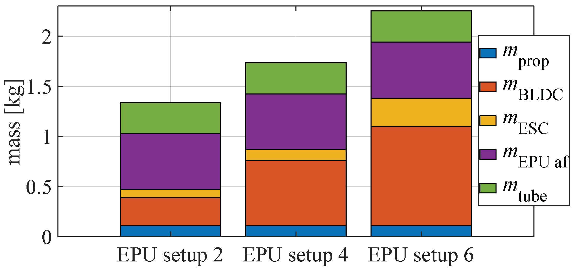
From the perspective of the efficiency of the propulsion configuration, it is necessary to take into account the characteristics but also the mass of individual setups. The mass of the propulsion module is provided with:
where
N is the number of rotors,
is the mass of the propulsion module central assembly, and
is the mass of the arm with the mounted EPU. The mass of the EPU consists of the BLDC motor mass (
), which has the largest share in the mass of the propulsion module rotor arm subassembly, the mass of the ESC (
), and the mass of the propeller (
). The components of the EPU are connected to the central assembly via the rotor arm airframe parts (
) and the carbon tube (
), and the rotor arm subassembly mass is provided with:
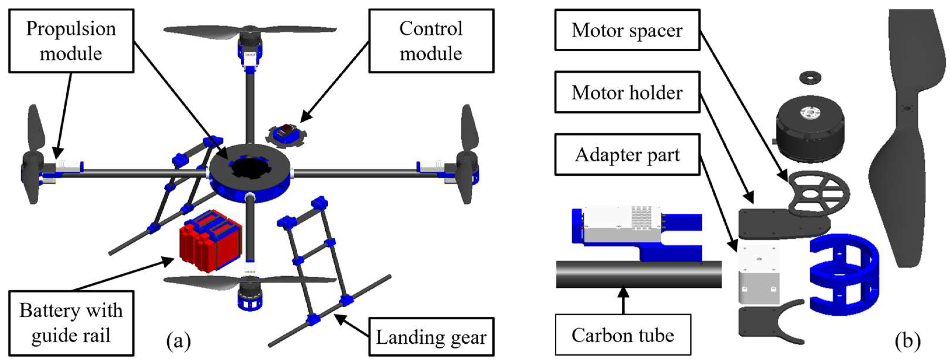
Designing the airframe parts of the propulsion module assembly is the most complex task since there are the highest mechanical loads as well as thermal loads and vibrations. From the aspect of modularity of the platform, the design of the rotor arm which allows the assembly of three conventional arm settings in the pusher, puller, or coaxial variants is considered. It is important to highlight the main feature of the proposed modular platform, which is made possible by the proposed central assembly of the propulsion module, which essentially enables the connection of other modules and the assembly of multirotor configurations with four, six, or eight rotors in a symmetrical arrangement.
There are various approaches that can be used to produce the system parts. Given that heavy lift customized aircraft are considered in this paper, where small series are required for potential applications, rapid prototyping technologies are used to produce the parts, along with available elements (for example composite tubes and plates). There is a special emphasis on the use of additive manufacturing (AM) technologies, primarily continuous fiber fabrication (CFF) technology for the production of parts with required mechanical properties due to the high power of the propulsion module and large mass. Conventional technologies, such as milling, to produce parts of the propulsion module from aluminum, were also considered. After the design and production, airframe parts along with system components are assembled into functional sub-assemblies and module assemblies where the total mass of the propulsion module consists of the mass of the propulsion central assembly and the masses of rotor arms which are shown graphically in
Figure 8.
3.2. Energy Module Components and Parameters
The energy module should provide enough energy for the propulsion module of the multirotor aircraft, which is characterized by high energy consumption. In general, when choosing the components of the energy module, several parameters should be taken into account. Given that configurations consisting of EPUs with BLDC motors were considered, LiPo batteries are imposed as the energy source. Their very important characteristic is high energy density, which is a favorable property for use in multirotor UAV systems. Furthermore, compared with other types of batteries, they have a higher discharge rate, which enables more power and a consistent flow of energy to the propulsion module. In this paper, the HV setup of the energy module with associated components is considered. In addition to batteries, as the basic components of the energy module, there are also distribution and measuring elements. Due to the requirements for different voltage levels, components were selected consisting of the Power-Cube electronic circuit for voltage conversion, power distribution and connection to the control system, and hubs with associated sensors [
48]. In terms of dimensions, the heaviest component is the Power-Cube 4, which weighs 130 g and measures 101 × 58 × 24 mm. The choice of sensor hub depends on the number of batteries since each one comes with a sensor. The hub for two sensors, which weighs 16 g, and the hub for eight sensors, which weighs 59 g, are used. Depending on the propulsion configuration, 50 A sensors weighing 23 g and 200 A sensors weighing 45 g are used. Measurements of the battery electrical parameters are forwarded to the control unit, and the battery condition can be monitored in real-time using telemetry.
LiPo batteries are high energy density rechargeable batteries defined by the number of cells that determine the operating voltage
, capacity, and discharge rate C. From the aspect of the state-of-charge (SoC) battery, the nominal voltage of an individual cell is defined as 3.7 V, and the voltage of a fully charged cell is 4.2 V. Battery capacity, which is usually expressed in mAh, is directly correlated with endurance. The discharge rate C defines the maximum energy transfer, that is, the maximum current that the battery can provide. Several series of HV batteries are available on the market, where, in addition to the above parameters, they are defined by price, number of cycles, and additional equipment for charging and storage. When choosing batteries, the energy requirements of the propulsion module must be taken into account, which in turn depend on the mass and size of the aircraft and the number of propulsion units. Considering that the battery is the component with the largest single share in the mass of the overall system, it follows that the relationship between the mass and capacity of the battery is key.
Table 5 shows the basic parameters of two battery manufacturers, namely Maxamps [
49] and Gens Ace [
50], required for system design.
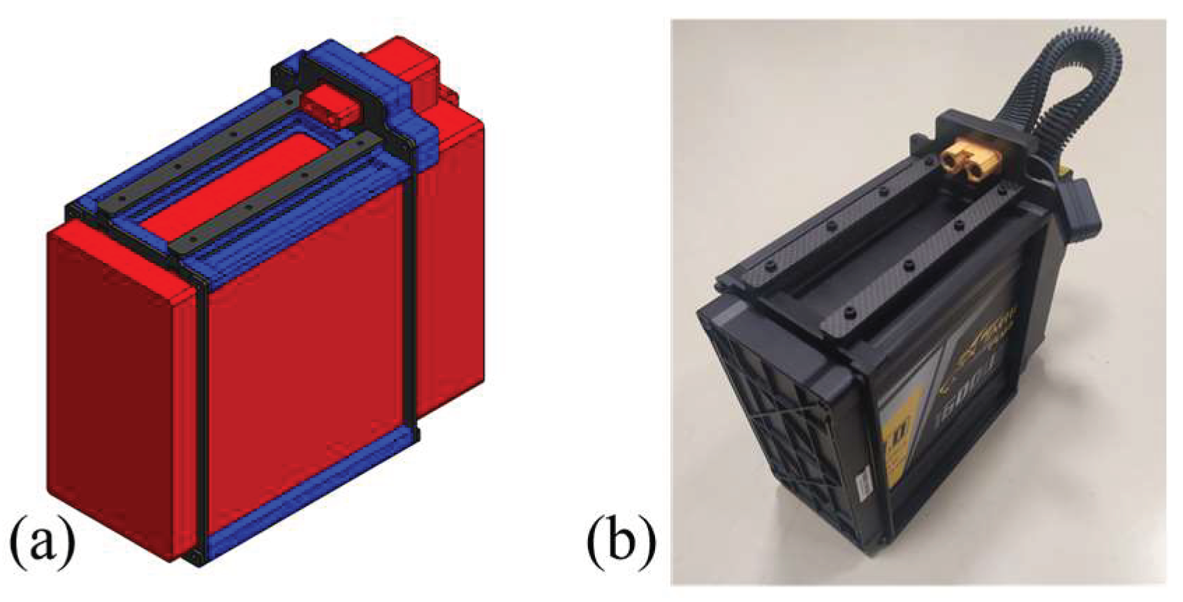
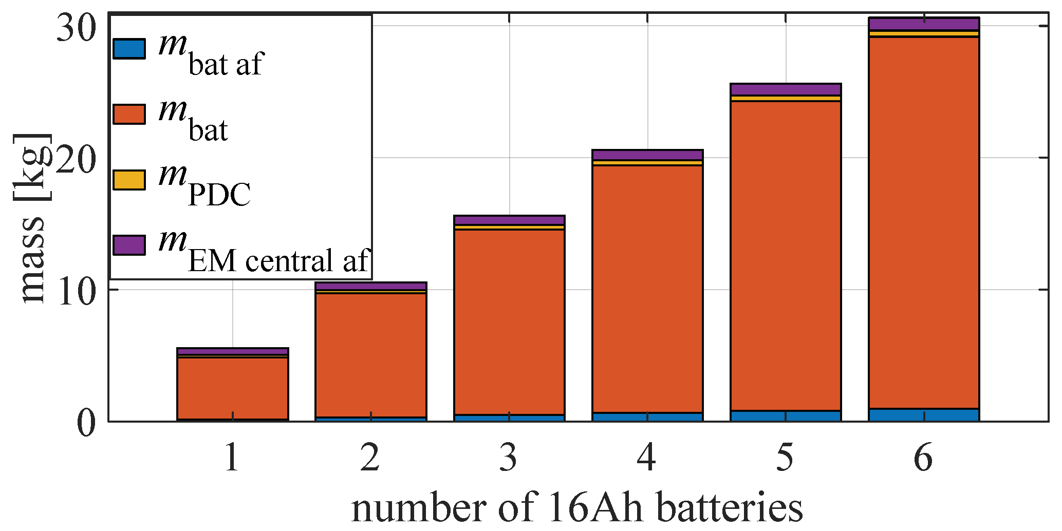
Conventional energy modules consist of the one or more batteries (battery packs) with mass
. Each battery is encased with airframe parts that have mass
, where it is important to note the case’s feature that consists of rail guides for quick and easy battery changes as shown in
Figure 9. This detail is extremely important in terms of further increasing the level of the system autonomy, where automatic battery replacement would be enabled. The mass of components and elements for energy distribution (power) and measurement of electrical quantities is provided with
, which are assembled into energy module central airframe subassembly and have mass
. The mass of the energy module is provided with following expression:
Basically, the battery can be placed vertically or horizontally regarding the central airframe. Given that one battery was used in the preliminary phase of testing, a test case was fabricated for the horizontal placement of the battery. Since the use of one or more batteries is further considered, a vertical arrangement of batteries is proposed.
The mass of a conventional energy module consisting of one or more LiPo batteries is shown in
Figure 10. Given that the mass of the batteries in relation to the other masses of the system dominantly affects the dynamics of the aircraft, it is preferable to place the energy module centrally, as close as possible to the aircraft CoG. Based on the total mass of the aircraft and the characteristics of the propulsion units, it is possible to estimate the energy required to maintain the stationary condition of the aircraft (hovering). This information is important because it is possible to assess which combinations of propulsion and energy modules are feasible, given the mission requirements.
3.3. Concept of Modular Aerial Platform for Heavy Lift Payloads
The assembly of the proposed novel aerial robotic platform consists of the considered propulsion and energy module, control module (avionics), and equipment module. One of the possible topologies discussed further allows the control module to be connected to the upper side of the central assembly of the propulsion module. In the case of the aircraft intended for experimental testing, the control module is based on an open source PX4 ecosystem [
51] with Cube FC which, together with the peripheral components of the FC and remote-control elements, is embedded inside the housing. The energy module consists of a receiving assembly for one or more batteries that are mounted on the bottom side of the propulsion module, as shown in
Figure 11. Each battery is integrated with rails that enable faster assembly of the overall system. The proposed concept of a robotic platform for heavy payloads is being considered for use in the logistics and agriculture sectors.
Table 6 provides an overview of the configurations that can be preassembled for the proposed modular robotic platform concept. Conventional configurations can be in + or X while coaxial configurations in Y and X geometric arrangements. Furthermore, fully actuated configurations with passively tilted hexa (PTX6) and octorotor (PTX8) are considered, where it is possible to preset the tilt angle in four values. In the next section, the simulation results for the X6 and PTX6 configuration and the experimental results for the quadrotor (X4) are presented.
From the aspect of the application of the proposed platform in the field of precision agriculture, more specifically for missions that include spraying, fertilizing, or sowing, there are different needs for the payload that depends on the type of application, plot area, speeds, and other parameters. The characteristic of such a payload is that it has a variable mass, thus changing the physical parameters of the aircraft’s rigid body (mass and moments of inertia). The equipment for such missions consists of a tank and various mechanisms that can be in the form of a dispersal assembly or, for example, a pump, manifold, and nozzles for dispersing liquid payload. It is important to note that there are commercial solutions that can be integrated with proposed platform modules. An important segment here is the equipment for take-off and landing, the so-called landing gear, which should be compatible with other modules and equipment of the system. In the example of the development of the landing gear assembly, the procedure for designing and manufacturing airframe parts using rapid prototyping technologies is presented (
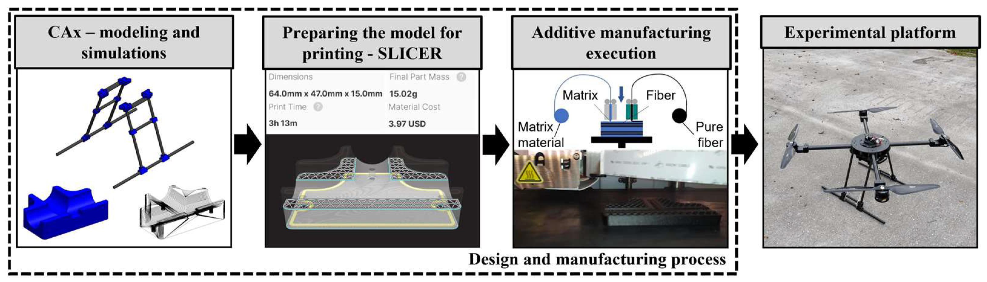
Figure 12).
In the first phase of the design process, CAx techniques [
52] are used, where the SolidWorks software package is employed for 3D modeling of parts and assemblies, and which provides a wide range of functions, such as the simulation of structural assemblies from the aspect of mechanical loads. The second phase consists of manufacturing physical models of the airframe, mainly with the help of rapid prototyping technologies, with an emphasis on AM technologies. Composite materials that are standardly used in the production of UAV parts [
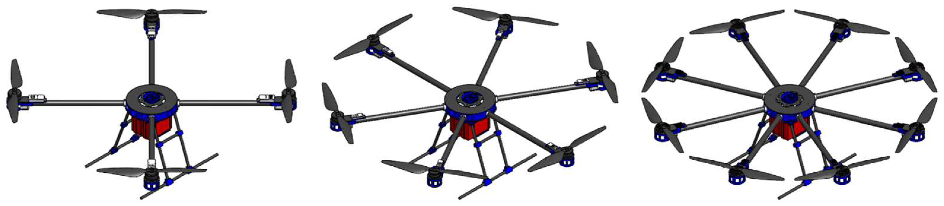
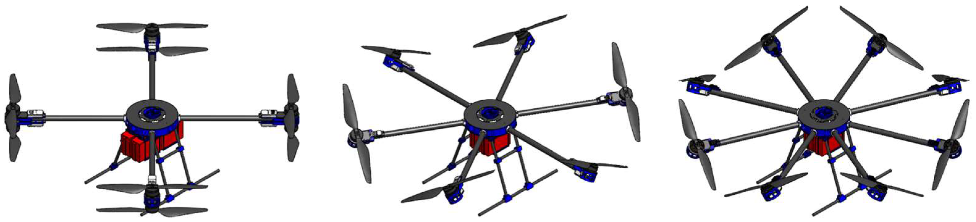
53] are also used. To produce parts of the experimental aircraft landing gear, elements fabricated of carbon fiber tubes and plates were used, which were integrated into the assembly together with elements fabricated with CFF technology. Using a 3 Axis CNC machine with the corresponding rotary tool airframe parts were fabricated from plate elements. The AM execution of the model was preceded by the adjustment of printing parameters that affect the mechanical properties of the model, production time, material consumption, and price. A Markforged Onyx Pro 3D printer was used with the associated Eiger slicer software, which enables manufacturing using CFF technology. The advantage of this technology is the possibility of parametrizing parts by combining different parameters and combinations of a matrix (nylon) and reinforcement (fiberglass) materials, and in the broader picture combining printed parts with those fabricated of composite materials, such as plates and tubes. With regard to the discussed technologies, it is important to take into account the characteristics of the propulsion units in terms of dimensions, mechanical loads, heating, and other influences when designing and modeling the propulsion airframe elements. The proposed concept allows the assembly of conventional configurations with four, six, or eight rotors, and
Figure 13 shows CAD assemblies consisting of different setups of the propulsion and energy module.
In the conceptual design phase, two basic ratios, mentioned earlier, are imposed, based on the aircraft take of mass, energy consumption in stationary flight, and the capacity of the battery pack. Given that the choice of components and parameters of the propulsion and energy module are interdependent, a balance must be maintained during the selection in order to meet the required performance with the existing constraints. The main goal is to select the parameters of the aircraft, in the case of conventional configurations, the EPU setup and the geometric arrangement of the rotors and the required capacity of the energy module, to increase efficiency and reduce energy consumption.
For the considered configurations,
Table 7 shows the mass of the system, power consumption in the stationary state (hovering), and the capacity of the energy module. Given that the TWR ratio, which is equal to 2, was considered, the total mass of the system is obtained based on the characteristics of the thrust force (20). Regarding the masses of the propulsion and energy modules that were previously defined, it is possible to extract the available payload mass
. From the aspect of energy consumption, and bearing in mind that it is a HV platform, energy modules were selected with a ratio of capacity to hovering power of 7 to 10 Ah/kW.
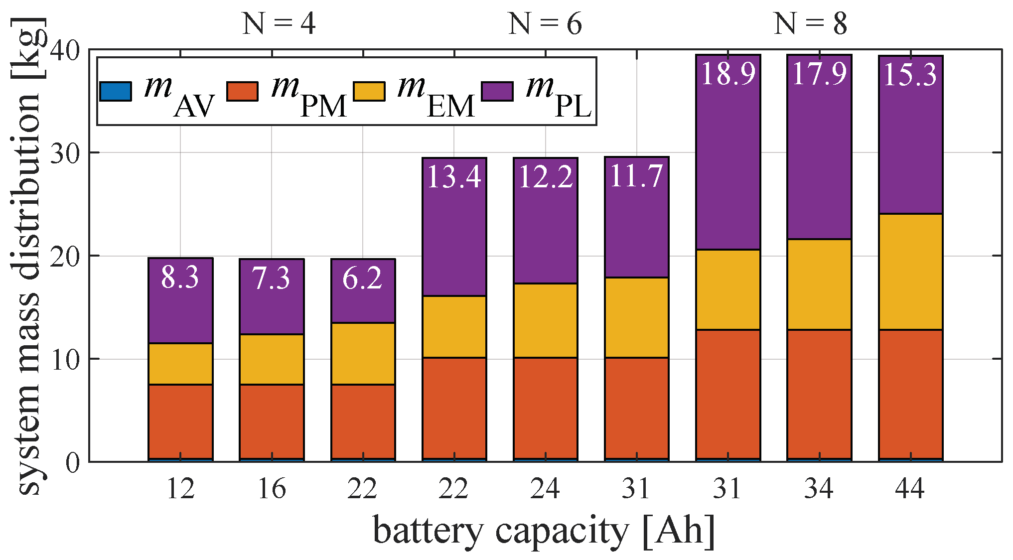
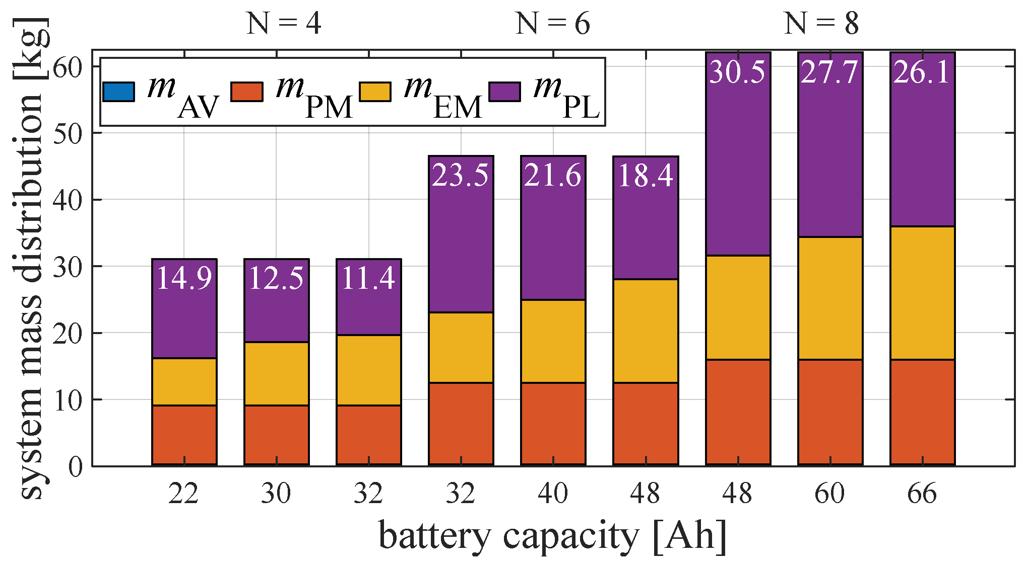
Figure 14,
Figure 15 and
Figure 16 shows the mass distribution for individual series of aircraft that form the components of three selected EPU setups and Maxamps batteries provided in
Table 5. The graphs show the potential payload that each configuration can carry with regard to the considered capacities of the energy module, whereby feasible configurations can be selected based on the ratio of capacity and energy consumption in the stationary flight.
Taking into account the selected working package (EPU setup, number of rotor units, capacity, and number of batteries), the proposed modular platform covers a wide range of payloads, from 5 to 50 kg. With regard to the considered range of applications, energy consumption is important, which can be estimated based on experimental parameters and predefined flight paths. Based on the presented distribution of masses, they can serve as recommendations for choosing the preliminary parameters of the propulsion and energy module with regard to the given payload, and they can also be used in simulations of individual missions to optimize the overall system. In addition to the shown conventional configurations, the proposed concept of a modular aircraft also allows the assembly of, for example, planar configurations with a coaxial arrangement of the rotors. Furthermore, non-planar configurations can also be realized as shown in
Figure 17, where fully actuated aircraft with passively tilted rotor arms are considered for potential solutions in applications with specific tasks where complex movements are required.
3.4. Toward Fully Actuated Multirotor Configurations
There are numerous studies of so-called non-planar configurations with the aim of reducing energy consumption, such as the triangular configuration with four rotors presented in paper [
33]. Furthermore, from the aspect of stability, configurations with dihedral angles have been considered, such as the quadrotor for which the effects of tilting the rotors inwards that were analyzed in [
54]. Of particular importance are fully actuated multirotor configurations that can perform complex and precise movements and therefore represent omnidirectional aerial robots. The presented concept of the modular aircraft allows the assembly of configurations with passively tilted rotor arms, such as the fully actuated hexarotor (PTX6) or octorotor (PTX8) shown in works [
31,
55]. In addition to the fact that such configurations can perform complex maneuvers, they are also more resilient to disturbance, which is important regarding the attenuation of external disturbances. For configurations with passively tilted rotor arms, the key parameter for the distribution of aerodynamic forces and moments to the aircraft control vector is the tilt angle. Based on experimental measurements, an analysis was carried out and the results for the range of tilt angles from 10 to 40 degrees for the configurations shown in
Figure 16 are presented.
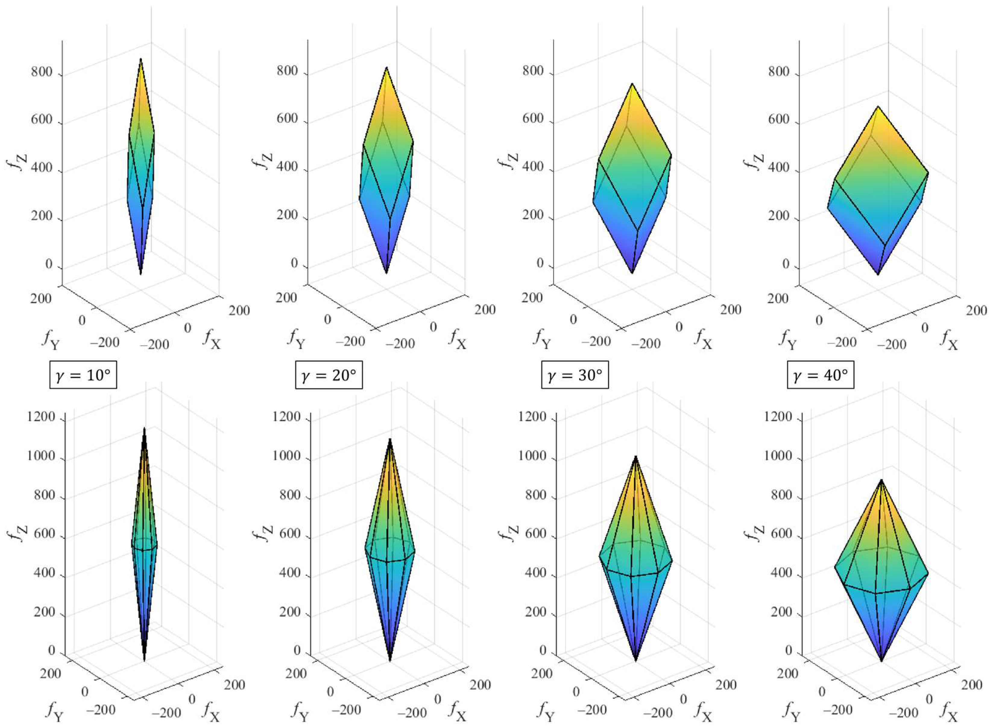
The thrust force distribution of configurations with six and eight passively tilted rotors was considered. Given the selected geometric arrangement, the movement of the aircraft in 3D space can be realized by generating vertical and horizontal forces in the body frame. Fully actuated configurations with passively tilted rotors have polyhedron-shaped force boundaries. Using the algorithm presented in the previous research [
56], for which an integral part was the allocation scheme of the model, a cloud of points was generated where each point represents the maximum available thrust forces in a certain direction. For visualization, the boundary surface method was used, so that in the configuration with six rotors (PTX6), the polyhedron is bounded by six rhombuses as shown in the upper row of
Figure 18, while in the configuration with eight rotors (PTX8) it is bounded by sixteen triangles as shown in the bottom row of
Figure 18. The forces marked on the graph (in Newtons) actually represent the forces of the propulsion subsystem
. The feature of this concept is that it enables the assembly of configurations with four different tilt angles that are selected during the assembly phase of the propulsion module. A significant disadvantage of such configurations compared with conventional ones is that maintaining the necessary performance of stationary and vertical flight requires higher energy consumption, and thus shortens the flight time. On the other hand, the amount of the horizontal component of the force increases so that the aircraft can perform horizontal movements without the need to change orientation. The performed analysis can be further extended and used to investigate energy consumption, agility, effects of aircraft size (power), and disturbance rejection, among others.
4. Simulations and Experiments
Considering that the multirotor type of UAV represents a complex system, behavior validation is a fundamental step in the development process in order to avoid costly damage and dangerous situations. For the needs of the stage of performing simulations and experiments, components and software support that enable system testing were selected.
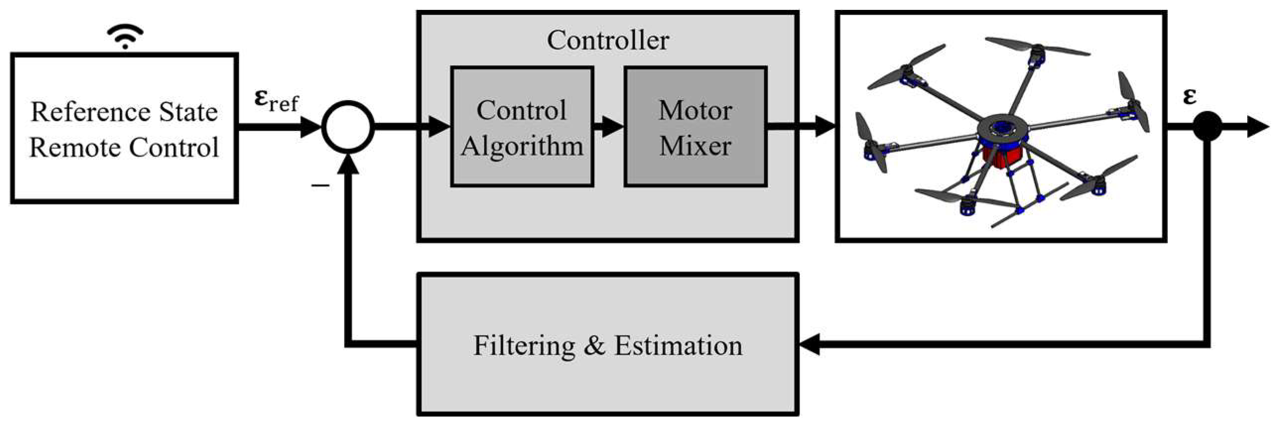
Figure 19 schematically shows the control system of the multirotor UAV that is used for experimental testing. To begin with, it is necessary to implement the described mathematical model into a software package that enables simulations of aircraft behavior with different parameters of aircraft configurations. The control design is based on the PX4 ecosystem, which consists of a hardware part in the form of a module with Pixhawk Cube FC and open-source software. This is a key fact that allows a large number of researchers and end users to develop the system. The considered FC has a modular software architecture, so it is possible to add new modules/applications, resulting in new functionalities of the individual system. From the aspect of this research, it is a big advantage that there is also support for MATLAB Simulink in the form of a toolbox. This allows the MATLAB software package to interact with the Pixhawk FC in real-time; therefore, accelerating research processes since the same software can be used for simulations and experiments.
The controller block consists of a control algorithm and the allocation of control variables to propulsion configuration. In the case of autonomous flight, the reference state can be predetermined and planned depending on the type of mission. Some missions consist of tasks such as collision avoidance, and furthermore aircraft may interact with the environment; therefore, depending on the mission, the aircraft is equipped with a set of sensors. In the case of remote control, the pilot sets the reference state, i.e., by moving the sticks on the remote controller, the pilot directly controls the aircraft. For the purposes of performing simulations and experiments, two control algorithms were implemented for underactuated and fully actuated multirotor configurations. First, the synthesis of the cascade structure controller was carried out, starting from the fastest control loop in the hierarchy to the slowest one whereby each control loop is observed separately. Then the synthesis of the linear quadratic regulator (LQR) was carried out.
4.1. Simulation Results
The implementation of simulations of a typical task in precision agriculture, which is based on realistic aircraft parameters obtained through the design and prototyping phases, was considered. Flight planning is a complex process, it depends on the mission, external influences, and the configuration of the aircraft. Two configurations were chosen for the simulations, a conventional (planar) configuration with six rotors (
Figure 12) and a configuration with six passively tilted rotors (
Figure 16). Furthermore, one of the specifics of the application of aircraft in precision agriculture in missions that include spraying, fertilization, or sowing is the variable payload mass, which affects the total mass and moments of inertia of the aircraft. By conducting computer simulations, the goal is to reduce the possibility of a flawed selection of system components and parameters, which shortens the time and costs of prototyping. Furthermore, the goal is to reduce energy consumption for more efficient mission performance, which can be achieved with a methodological approach that integrates the characteristics and parameters of the propulsion system into the aircraft mathematical model.
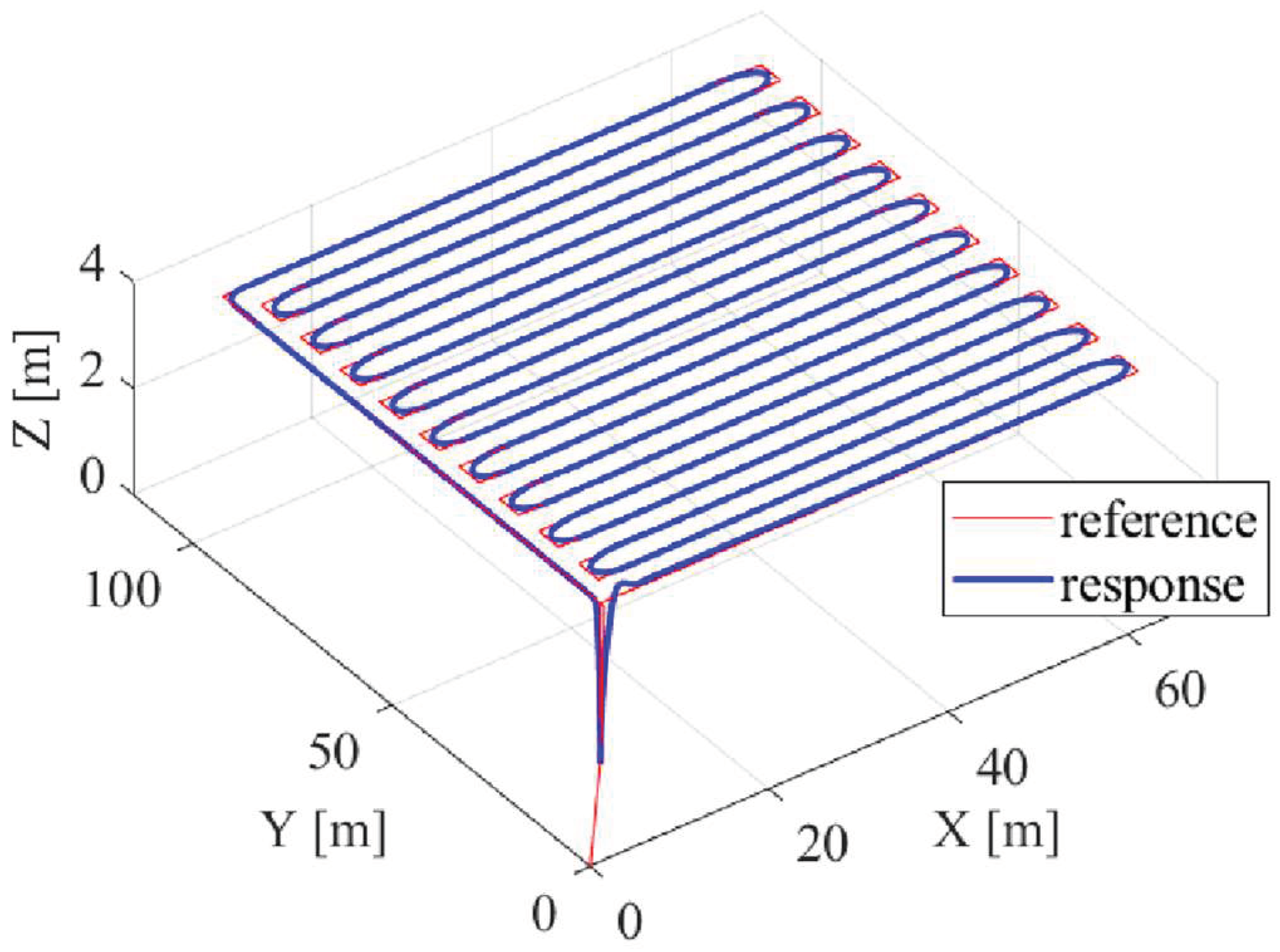
First, the results of simulations for a hexarotor configuration that follows a reference trajectory at a speed of 2 m/s, and sprays a chemical agent or fertilizer are presented. The physical parameters of the aircraft, mass, and inertia were obtained based on the aircraft CAD model, which consists of real materials that are used in the prototyping process. The aircraft model is equipped with a 15 L tank (15 kg), the spraying speed is 1.5 L/min, and the plot area is 6000 m
2. The goal of the simulation is to verify the implemented model, and arbitrary mission parameters were taken that are in the realistic range of commercial solutions and research conducted in the subject area. The obtained aircraft parameters at the beginning of the mission are
,
,
, and
. The system response is shown in
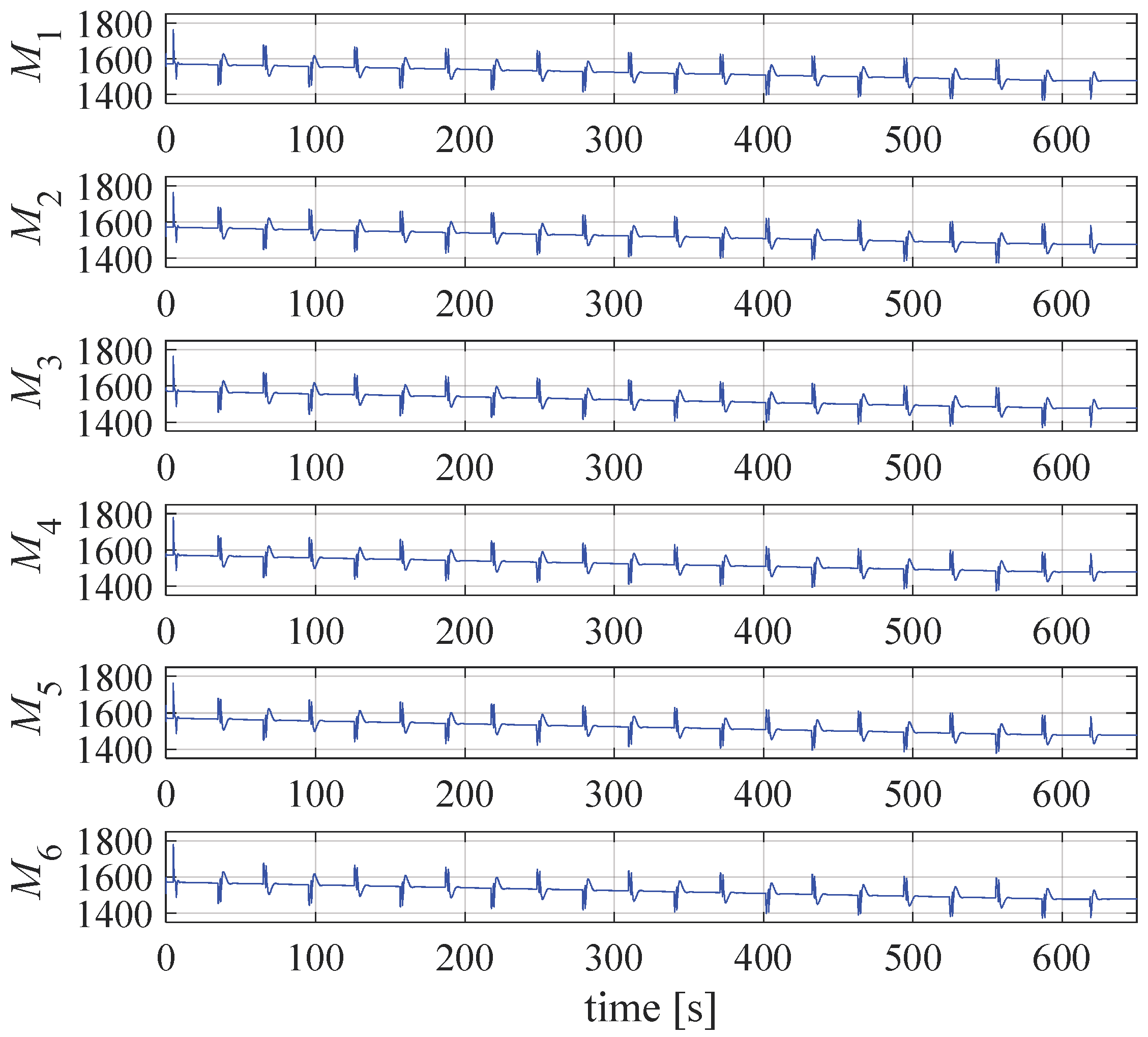
Figure 20, while
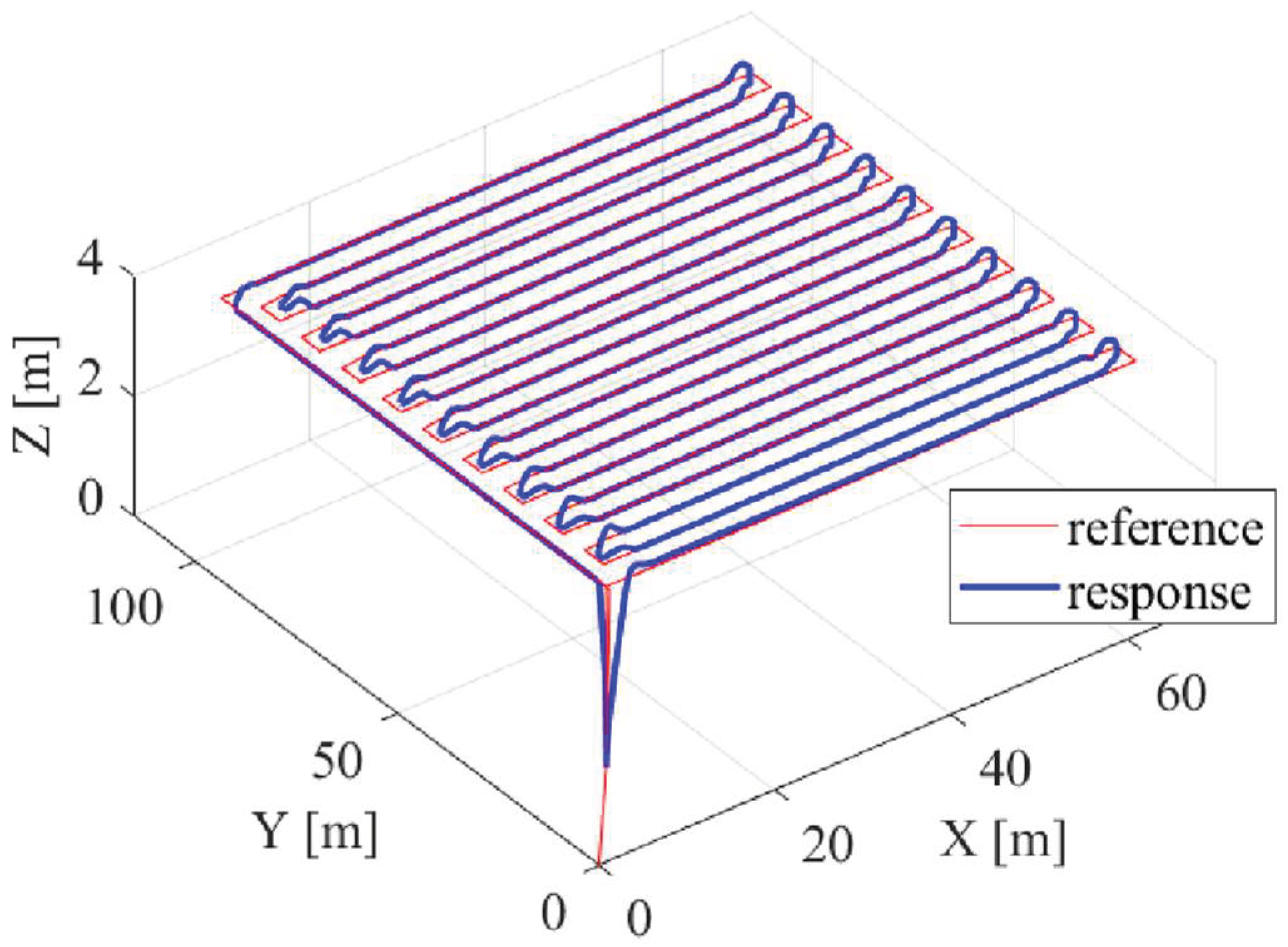
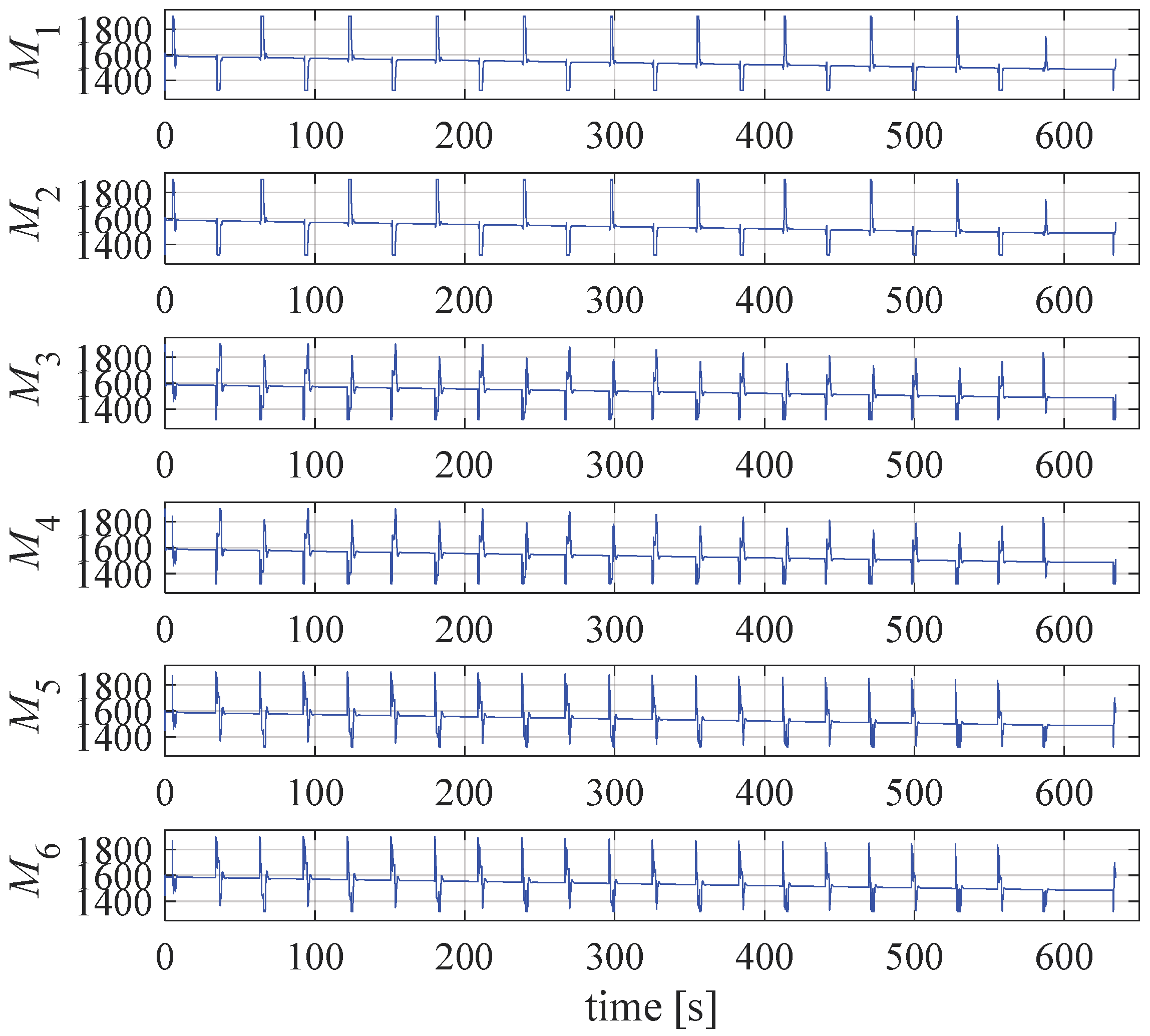
Figure 21 shows the PWM signals of the propulsion system. Furthermore, a simulation was also carried out for a fully actuated configuration with the same physical parameters. The simulation results in the case when the tilt angle is 20 degrees are shown in
Figure 22 and
Figure 23. In the simulation with a fully actuated aircraft, the position is achieved using the propulsion forces in the aircraft’s horizontal plane, and the orientation angles are kept at zero. In future work, it is planned to use the described framework for the estimation of energy consumption and system parameters optimization.
When performing the simulations, the dynamics of the propulsion were not taken into account. The main goal is the verification of the implemented model, with a special emphasis on the allocation considering underactuated and fully actuated configurations. With that in mind, a hexarotor without tilting rotors and one with tilted rotors were considered in the simulation phase.
4.2. Results of Preliminary Experiments
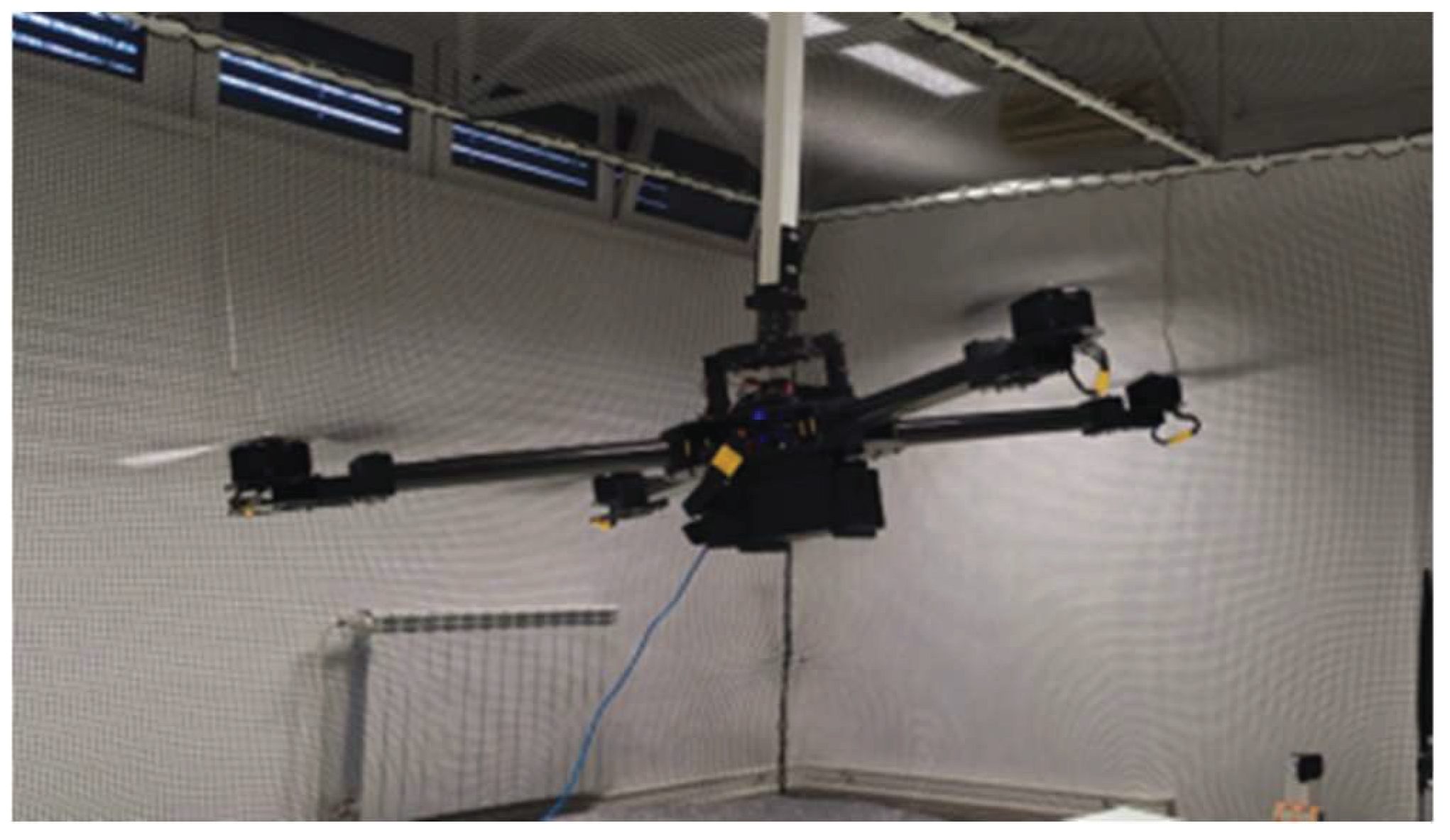
To validate the proposed modular multirotor UAV, and the experimental firmware a prototype consisting of four rotors was developed. The manufactured aircraft has a diameter of 1.4 m, and the rotors consist of setup 4 components, while the energy module consists of one Gens Ace Tattu battery with a capacity of 16,000 mAh. Given that the proposed concept is intended for missions with large payloads, the propulsion module is of high power, so it is important to ensure a safe environment from the testing point of view. For this purpose, a three-axis gimbal was fabricated, which allows testing the attitude control of the aircraft with a fixed position, thus enabling the testing of the aircraft of large size and power in laboratory conditions, as shown in
Figure 24.
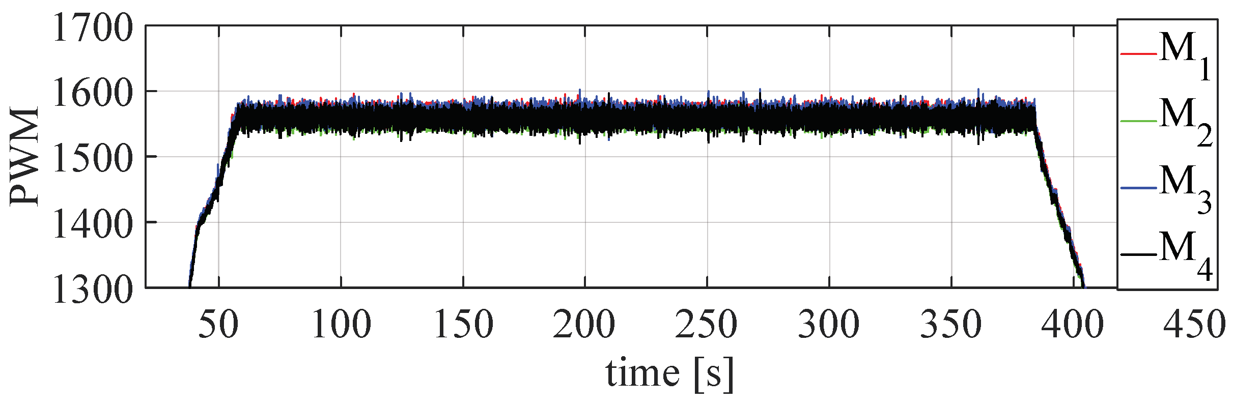
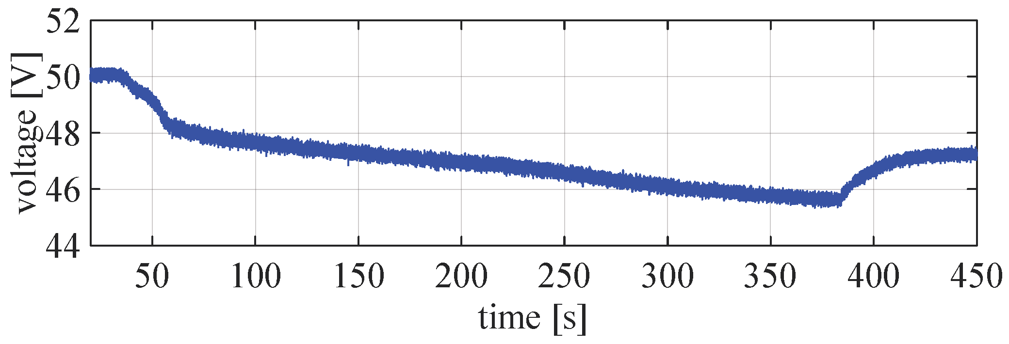
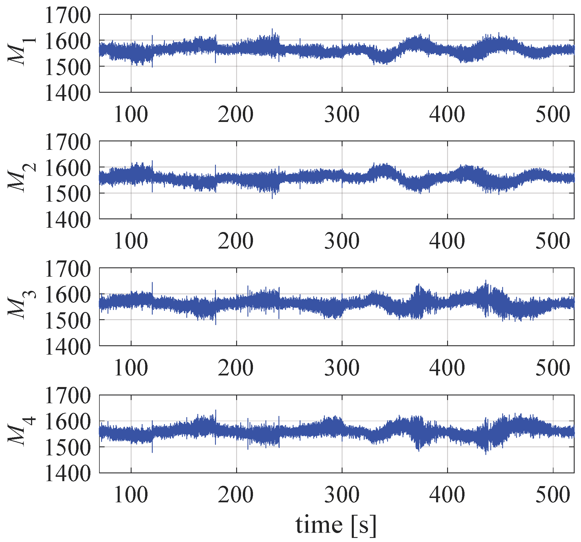
In this phase of testing, the aircraft assembly was checked under various loads and a test procedure was established to avoid fatal errors. For the purposes of controlling the aircraft, two control algorithms, the cascade proportional–integral–derivative (PID) controller and the LQR were implemented. The first experiment was carried out by testing the aircraft in a stationary state (hovering) for a given PWM offset signal. The signals of individual motors during the hovering test are shown in
Figure 25, and the voltage drop is shown in
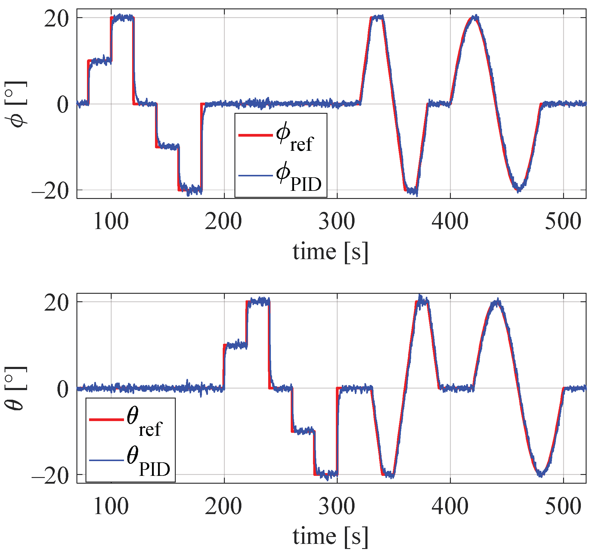
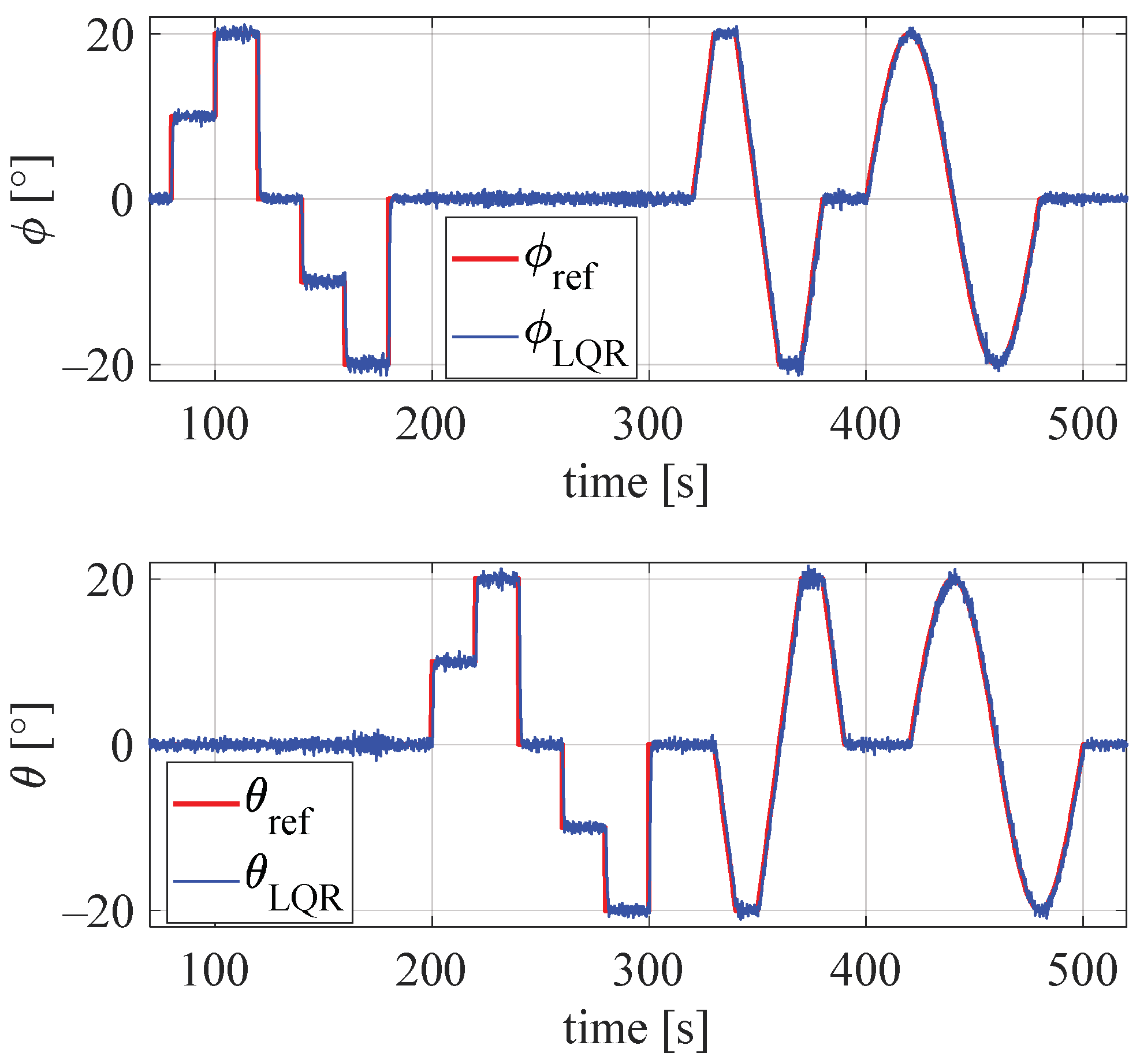
Figure 26. The following series of experiments were carried out for the case of tracking the reference state (angles phi and theta). First, an experiment was made using a cascade PID controller for the case of tracking a reference orientation consisting of several segments. Response of the aircraft is shown in
Figure 27, while PWM signals for individual motors are shown in
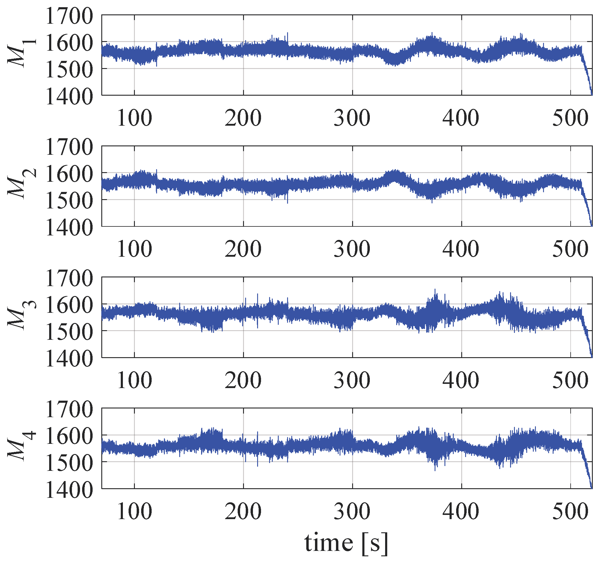
Figure 28. Furthermore, LQR was tested for the same settings of the reference state, and the response of the aircraft is shown in
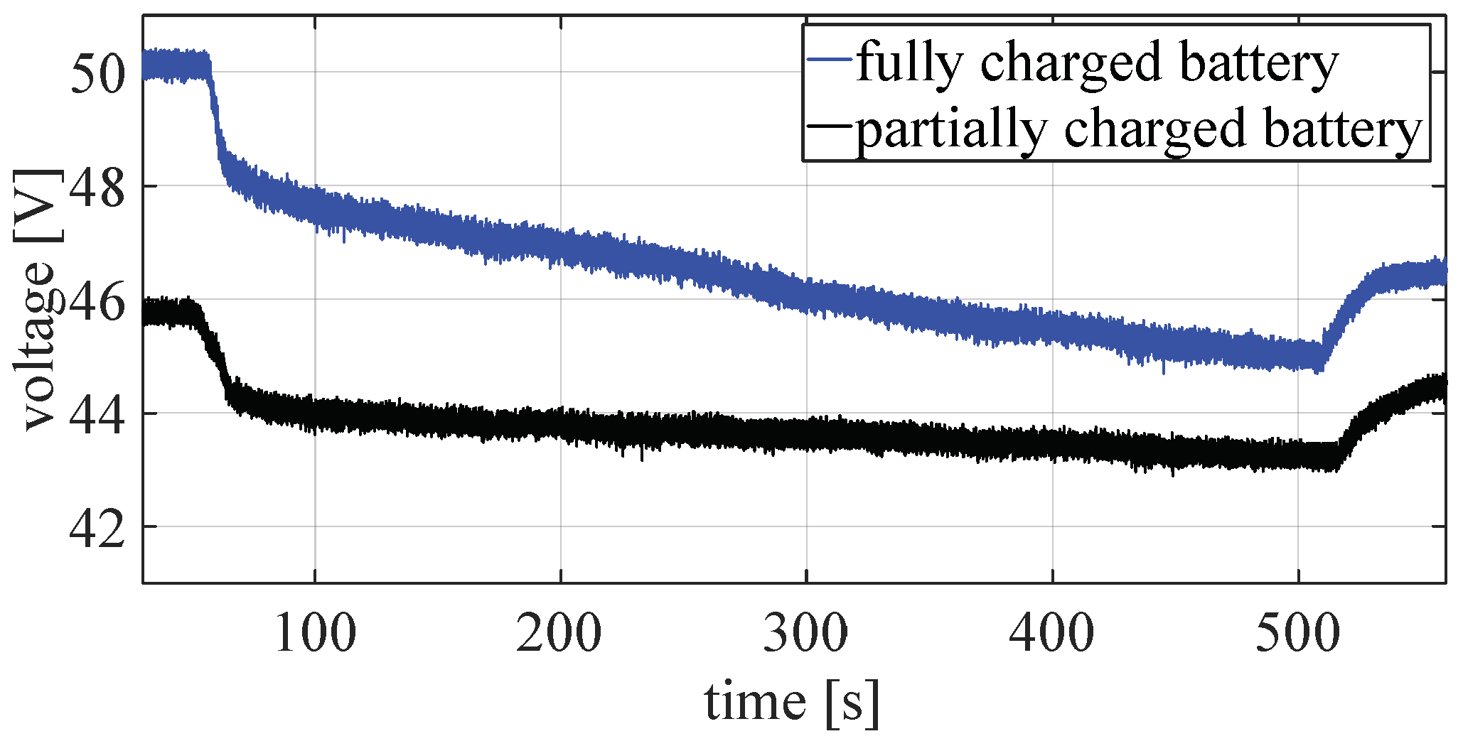
Figure 29 while PWM signals are shown in
Figure 30. This test was performed with a fully and partially charged battery, as can be seen from
Figure 31.
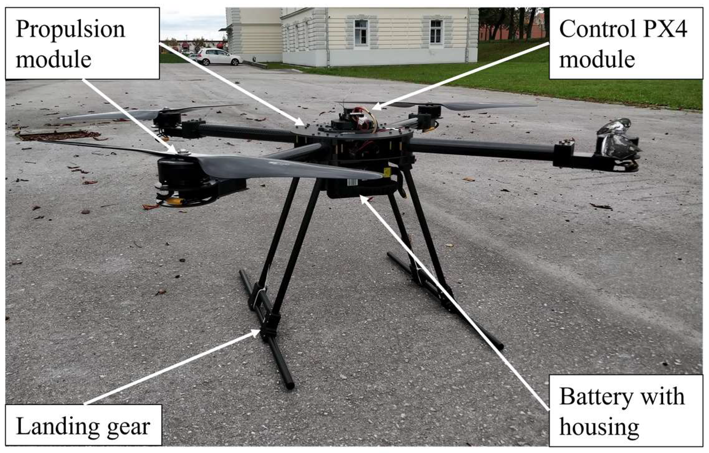
In further work, extensive tests in laboratory conditions are planned for the purpose of testing the safety elements of the control system and adjusting the controller parameters with the aim of testing the aircraft outdoors. For this purpose, a 6-axis force and moment sensor will be integrated into the existing laboratory environment. The fully assembled quadrotor prototype is shown in
Figure 32. The mass of the prototype propulsion module is 8.7 kg, the mass of the landing gear is equal to 1.3 kg, and the mass of the control module is 0.35 kg. The mass of the energy module depends on the number of batteries, the module with one battery has a mass of 5.6 kg, while the module with two batteries has a mass of 10.8 kg. Taking into account the TWR = 2 and measured thrust forces for the prototype setup 4, a single battery prototype is suitable for a payload of up to 15 kg, while with a dual battery can lift a payload of up to 10 kg.


