Article

Liquid Nitrogen Flow Boiling Critical Heat Flux in Additively Manufactured Cooling Channels

Aerospace Center, Department of Aerospace and Mechanical Engineering, The University of Texas at El Paso, El Paso, TX 79968, USA
*
Author to whom correspondence should be addressed.
Aerospace 2023, 10(6), 499; https://doi.org/10.3390/aerospace10060499
Submission received: 27 April 2023 / Revised: 19 May 2023 / Accepted: 24 May 2023 / Published: 25 May 2023
(This article belongs to the Special Issue Heat Transfer, Combustion and Flow Dynamics in Propulsion Systems)

Abstract

:
This paper presents an experimental characterization of liquid nitrogen (LN2) flow boiling in additively manufactured minichannels. There is a pressing need of concerted efforts from the space exploration and thermal transport communities to design high-performance rocket engine cooling channels. A close observation of the literature gaps warrants a systematic cryogenic flow boiling characterization of asymmetrically heated small (<3 mm) non-circular channels fabricated with advanced manufacturing technologies at mass flux > 3000 kg/m2s and pressure > 1 MPa. As such, this work presents the LN2 flow boiling results for three asymmetrically heated additively manufactured GR-Cop42 channels of 1.8 mm, 2.3 mm, and 2.5 mm hydraulic diameters. Twenty different tests have been performed at mass flux~3805–14,295 kg/m2s, pressures~1.38 and 1.59 MPa, and subcooling~0 and 5 K. A maximum departure from nucleate boiling (DNB)-type critical heat flux (CHF) of 768 kW/m2 has been achieved for the 1.8 mm channel. The experimental results show that CHF increases with increasing LN2 flow rate (337–459 kW/m2 at 25–57 cm3/s for 2.3 mm channel) and decreasing channel size (307–768 kW/m2 for 2.5–1.8 mm channel). Finally, an experimental DNB correlation has been developed with 10.68% mean absolute error.

1. Introduction

Cryogenic fluids exhibit some unique characteristics, such as low surface tension, low liquid viscosity, low latent heat of vaporization, small density difference between the liquid and gas phases [1], and large compressibility [2]. These unique thermophysical properties of cryogenic fluids have contributed to its application in the multitude of terrestrial and space systems including cooling of high-temperature superconductors [2,3], cryosurgery [4], metal processing [5], air separation units, chilling down of telescopes and satellites [1], regenerative cooling of liquid rocket engines [6,7] and so on. In regeneratively cooled rocket engines, the propellant or the oxidizer flows through the cooling channels surrounding the combustion chamber and nozzle walls to absorb heat and maintain the structural integrity of the thrust chamber [8,9]. During regenerative cooling, four different heat flux regimes appear to exist to control the wall temperature [10]. At low heat flux values, single-phase forced convection forms a liquid boundary layer to absorb heat from the hot wall. As the imposed heat flux increases, the wall temperature increases significantly to sustain the nucleation of vapor bubbles. The vapor bubbles grow, depart from the wall generating local turbulence, and finally collapse in the bulk cooler liquid. Due to bubble dynamics, a large amount of heat is absorbed via latent heat stored within the coolant in this regime. This regime is known as nucleate boiling and it usually appears in the nozzle throat area. Further increase in heat flux results in the competition between vapor generated at the wall and the replenishing liquid until the hot wall reaches critical heat flux (CHF). Two types of CHF events are encountered for cryogenic cooling, known as departure from nucleate boiling (DNB) type CHF and dry-out type CHF [1]. During DNB, the vapor bubbles from the wall are unable to penetrate the highly sub-cooled liquid core flow at high mass flux resulting in a localized vapor blanket. Conversely, during dry-out type CHF, annular liquid film appears in the cooling channels at low degrees of subcooling and low mass flow rates. However, regardless of the type of CHF event, it identifies the maximum feasible heat transfer rate for the combination of given fluid–surface interface conditions. If the applied heat flux exceeds the CHF limit, an unstable vapor film acting as an insulation layer significantly increases the wall temperature. A further increase in wall temperature is associated with the radiation heat transfer regime due to a drastic increase in vapor film temperature. However, the cooling channel design aims to avoid both the unstable gas film and radiation heat transfer regimes to achieve efficient cooling and structural integrity. Therefore, it is essential to identify the CHF limits in the design of two-phase systems.
A variety of publications have reported flow boiling CHF values for cryogenic liquids including liquid hydrogen (LH2), helium (LHe), nitrogen (LN2), and methane (LCH4). In 2021, Ganesan et al. [1] consolidated 2312 CHF data points from world cryogenic literature dating back to 1959. The database contains single component cryogens flowing vertically upward or downward, and horizontal, and symmetrically heated straight stationary circular channels. Some consolidated results are presented in Figure 1. Figure 1a presents the number of available CHF data points as a function of mass velocity. It can be seen that more data are available up to mass flux value of 3000 kg/m2 s. However, Cho et al. [8] performed regenerative cooling heat transfer analysis using SUPERTRAPP code for F-1 and RS-27A engines at 30,000 kg/m2s mass flux. Boysan et al. [11] performed numerical simulations to investigate the effect of cooling channel geometry for liquid propellant rocket engines using ~6000 kg/m2s liquid hydrogen mass flux. Moreover, Wang et al. [12] developed a multidisciplinary, computational methodology using a combination of CFD/thermal models to predict the hot-gas-side and coolant-side heat transfer for regeneratively cooled liquid rocket engine combustors where ~11,000 kg/m2 s mass flux was used for liquid hydrogen coolant. Therefore, it is essential to measure the cryogenic flow boiling CHF at large mass flux values.
Figure 1b presents the number of available CHF data points as a function of cylindrical tube diameter. Albeit there exists a significant number of CHF data points for small diameter channels (D < 3 mm) using Lhe, the flow boiling results below 3 mm channel diameter are limited for LN2, LH2, and LCH4. However, it is well-established that CHF increases with decreasing channel diameter. The slope of the velocity profile in the two-phase boundary layer increases with decreasing channel diameter. This effect with increased mass flux facilitates the bubble departure from the heated wall and increases condensation in the liquid core [13]. Wadel [14] performed analytical investigations on seven coolant channel designs using a coupling of the Rocket Thermal Evaluation code and the Two-Dimensional Kinetics code. The high aspect ratio cooling channel designs with hydraulic diameters varying from 0.49 mm to 0.94 mm showed hot combustion gas-side wall temperature reduction up to 22% with coolant pressure drop increasing to 7.5%. Van Noord et al. [15] conducted sub-cooled LCH4 boiling tests with electrically heated Inconel tubes of 0.66 mm, 1.4 mm, and 2.1 mm diameters and achieved ~10 MW/m2 CHF value for the 1.4 mm diameter channel. Therefore, it is essential to experimentally investigate the cryogenic flow boiling CHF using small channels.
Figure 1c presents the number of available CHF data points as a function of measured CHF values. It is evident that most of the measured CHF values are below 0.1 MW/m2, more specifically for LH2, Lhe, LN2, and fewer reported above for LCH4. Moreover, rocket engine thrust chamber walls are subjected to high heat transfer rates of 0.8–82 MW/m2 [16]. As such, cooling channel designs with high heat transfer capabilities appear to be a significant design consideration for rocket engines.
In addition to high coolant mass flux, small channel cross-sectional area, and high heat transfer rates, other factors, such as channel material, channel geometry, fabrication method and imposed heat flux direction, play significant roles in cooling channel design for liquid rocket engines. Significant experimental research has been reported on cryogenic flow boiling in symmetrically heated circular channels [1]. However, rocket engine cooling channels experience asymmetric heat flux from the combustion chamber hot wall [17,18,19,20]. Moreover, the effect of high aspect ratio cooling channels on increasing regenerative cooling performance and improving pressure drop is well-documented [18]. Wadel showed hot combustion gas-side wall temperature reduction up to 22% with coolant pressure drop increasing to 7.5% for high aspect ratio cooling channels [14]. Santhosh and Kuzhiveli performed two-dimensional heat transfer analysis for high aspect ratio channels and concluded that maximum cooling and minimum pressure drop can be achieved for an optimum aspect ratio value [21]. Wadel and Meyer showed a 27% reduction in pressure drop with 13% reduction in hot-gas-side wall temperature using high aspect ratio channel at low coolant flow rate as compared to conventional channel at full-scale mass flow test [22]. Carlile and Quentmeyer experimentally demonstrated that the combustion chamber wall temperature decreases by 30% as compared to the baseline low-aspect-ratio channel for the same coolant pressure drop [23]. Yet, a limited amount of research has addressed the experimental cryogenic flow boiling using non-circular geometries, such as square and high aspect ratio rectangular channels, more specifically asymmetrically heated non-circular cooling channels. Additionally, a vast majority of the cryogenic flow boiling tests have been conducted using stainless steel tubes while some researchers utilized nickel alloys and fewer employed copper and silver tubes [1]. However, Glenn Research Copper (GR-Cop) alloys are the preferred combustion chamber materials due to their high thermal conductivity, low creep and low-cycle fatigue, oxidation and blanching resistance, and high material strength at elevated temperatures with sustained operations [24,25]. Moreover, the National Aeronautics and Space Administration (NASA) has observed significant potential with additive manufacturing (AM) that offers reduced lead time and cost of fabrication for complex high-performance liquid rocket engine components. However, there is a lack of literature on the characterization of fuel film cooling in additively manufactured GR-Cop cooling channels [25]. Therefore, it is essential to investigate the cryogenic flow boiling heat transfer performance for the optimization of high-performance engine systems.
Motivated by the above-mentioned research gaps of cryogenic flow boiling tests in small asymmetrically heated non-circular channels of high heat transfer capability fabricated using advanced manufacturing technologies, this article aims to present an experimental characterization of cryogenic flow boiling heat transfer in additively manufactured channels. Here, GR-Cop square, and high aspect ratio rectangular channels have been used during sub-cooled and saturated LN2 flow boiling. The tests have been performed at a wide variety of mass flux values and different inlet pressure conditions up to CHF. The experimental CHF results are compared with experimental CHF correlations from the literature and, a modified CHF correlation has been developed for LN2 DNB-type CHF in asymmetrically heated non-circular cooling channels.

2. Materials and Methods

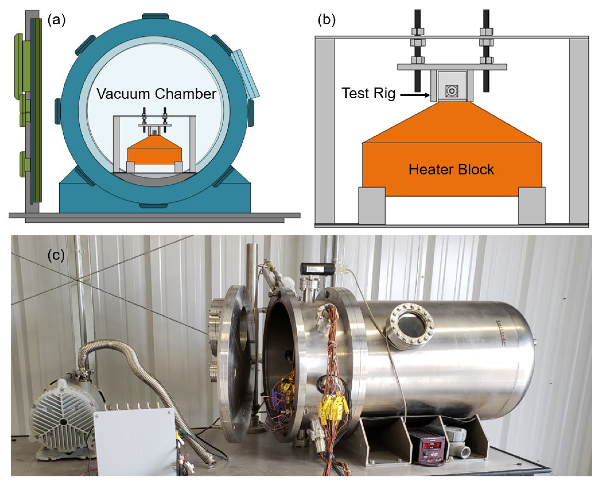
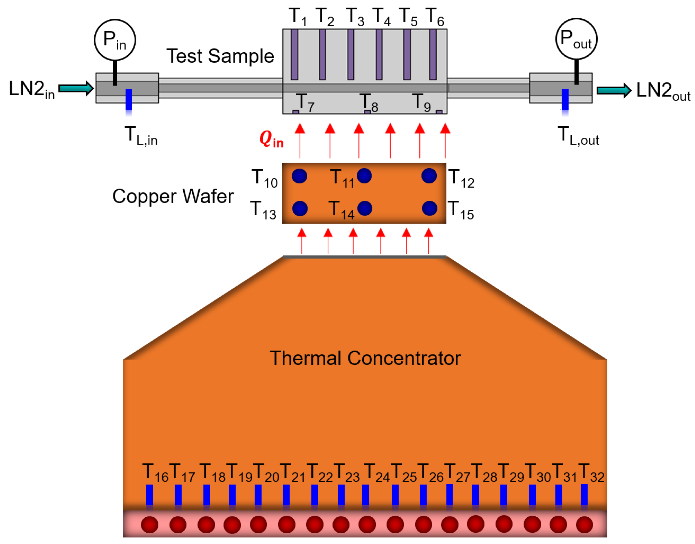
2.1. High Heat Flux Test Facility (HHFTF)

Cryogenic flow boiling experiments are performed using a high heat flux test facility (HHFTF), shown in Figure 2, capable of operating up to 4 MPa pressure and 755 K temperature using liquid nitrogen (LN2) and liquid methane (LCH4) as the working fluids [26,27,28]. The HHFTF is a thermal concentrator system based on conduction that asymmetrically transfers heat to a horizontal cooling channel resembling regenerative cooling during combustion. Tests are performed inside a vacuum chamber (Figure 2a) to reduce convective heat leaks during the tests and potential oxidation of components at high temperatures. A scroll vacuum pump is used to achieve a pressure of 6 Pa inside the vacuum chamber and remove fluid residuals and non-condensable gases from the flow lines. Vacuum pressure inside the chamber is measured using a convection-enhanced Pirani sensor with a Pirani gauge controller. A 316L stainless steel test stand is used to structurally support the test assembly and thermal concentrator inside the vacuum chamber. The custom-built test rig, heat flux sensor and thermal concentrator are compressed using a 6061-aluminum cradle to provide good thermal contacts. Figure 2b shows the schematic of test assembly with aluminum cradle inside the test stand. Nitrogen gas (GN2) is used to pressurize LN2 inside the high-pressure liquid cryogen dewar to pump LN2 to the test section. A pressure regulator is used to control the GN2 flow to the LN2 dewar. LN2 flow rate is adjusted using a precision needle valve. A turbine flowmeter is used to measure the flow rate. Static pressure transducers with thermal standoffs are used to measure pressure along the LN2 flow line at the inlet of the vacuum chamber, and at the inlet of the cooling channel. Two ungrounded sheathed type-E thermocouples are utilized to measure LN2 temperatures at the inlet and outlet of the cooling channel. A National Instrument Data Acquisition (NI-DAQ) system is used to monitor and record the measurements from all the sensors. Figure 2c shows the picture of the high heat flux test facility.

2.2. Thermal Concentrator

To provide asymmetric heating to the cooling channel, the HHFTF consists of a thermal concentrator, as shown in Figure 3. The thermal concentrator is a trapezoidal C12200 copper block that contains 17 cartridge heaters capable of generating ~7.2 kW power. The cartridge heaters are controlled using a variable transformer (VARIAC) of adjustable voltage ranging from 0 to 130 V. The safe operation of the cartridge heaters is monitored using 17 type-K thermocouples (Figure 3, T 16 T 32 ) inserted into the concentrator block near the base of the cartridge heaters. The thermal concentrator top has a surface area of 2.5 cm width × 5 cm length, resulting in ~5.7 MW/m2 heat flux capability of the HHFTF. The thermal concentrator assembly also contains a custom-built heat flux sensor to measure the given heat flux to the cooling channel during flow boiling tests. The heat flux sensor consists of a copper wafer of 2.5 cm width, 5 cm length and 6.35 mm thickness that contains six slots for thermocouples. The distance between the top three thermocouples (Figure 3, T 10 T 12 ) and bottom three thermocouples (Figure 3, T 13 T 15 ) is ~3 mm. Type-T thermocouples are inserted into the copper wafer to measure heat flux using the Fourier conduction law. Thermally conductive ceramic paste is used between the copper wafer and thermal concentrator and compressed with aluminum cradle, as shown in Figure 2b, to provide good thermal contact. Here, T L , i n and T L , o u t are the liquid nitrogen inlet and exit temperatures, respectively, and P i n and P o u t are the inlet and exit pressures, respectively.

2.3. Test Channels

Three different Glenn Research Copper (GR-Cop42), a copper-chrome-niobium alloy, and cooling channel designs have been fabricated and tested during the sub-cooled and saturated liquid nitrogen flow boiling tests in this paper. The test sections have been designed by the authors and fabricated by the National Aeronautics and Space Administration (NASA) Marshall Space Flight Center (MSFC). Powder Bed Fusion (PBF) advanced additive manufacturing has been used to fabricate the samples. To accommodate the feasibility of various cooling channel tests, the test rigs have been designed such that different cooling channels can be simply substituted for testing without affecting the wafer and thermal concentrator. The test section has a surface area of 2.5 cm width × 5 cm length to match the top surface area of copper wafer and thermal concentrator. Figure 4 shows the design of the test section. Figure 4a shows the cross-sectional view of the test section where w is the width, and h is the height of the cooling channel. Figure 4b presents the side view of the test section showing the cooling channel height, length, and thermocouple locations.
Table 1 presents the dimensions of the various cooling channels tested in this work. The variations in cooling channel designs include two square channels with hydraulic diameters of 1.8 mm (1.8 mm × 1.8 mm), and 2.3 mm (2.3 mm × 2.3 mm), and one high aspect ratio rectangular channel with hydraulic diameter of 2.5 mm (1.8 mm × 4.1 mm). All the channels have a heated length of 5 cm. Figure 4c shows the picture of the test section with the high aspect ratio 2.5 mm hydraulic diameter channel. The test section consists of an entry-length section ( ~ 10 D h , where D h   is the hydraulic diameter of the colling channel) to allow fully developed flow and exit-length section. The test section also includes six thermocouples located at the top of the cooling channel (Figure 4b, T 1 T 6 ), three thermocouples underneath the cooling channel (Figure 4b, T 7 T 9 ), one thermocouple at the LN2 inlet (Figure 4b, T L , i n ), and one thermocouple at the LN2 outlet (Figure 4b, T L , o u t ) along the flow direction. The distance between the tip of the thermocouple and channel wall is ~1.27 mm.

2.4. Test Procedure

LN2 flow boiling tests are performed in horizontal orientation starting with achieving ~25 Pa pressure inside the vacuum chamber. Initially, the tube lines and the test channel are cooled using a continuous flow of LN2 until the system reaches the desired temperature. This is an open flow system where the exiting nitrogen is released to the vent. Three different operating conditions are used in this paper: (i) 1.38 Mpa pressure and corresponding saturation temperature of 108.97 K, (ii) 1.59 Mpa pressure and corresponding saturation temperature of 111.42 K, and (iii) 1.59 Mpa pressure and sub-cooled temperature of 106.42 K (5 K subcooling). Once the desired temperature is reached, the LN2 flow rate is set to the desired value using the precision needle valve. Five various volumetric flow rate values are used in this paper: 25 cm3/s, 31 cm3/s, 38 cm3/s, 47 cm3/s, and 57 cm3/s. Then, the test section is heated by powering the cartridge heaters in the thermal concentrator at small increments. The steady-state data points are recorded at each increment of heater power when the temperatures of wafer thermocouples ( T 10 T 15 ) do not change more than 0.5 K for 1 min. A slow and gradual heat input is given to the test channels until a drastic increase in wafer temperatures is observed ensuring that the channel has reached a film boiling regime. This significant change in the nucleate boiling slope is identified as the critical heat flux (CHF) point for cryogenic boiling heat transfer [15]. Since the tests start at low temperatures (109 K or 113 K), system failure is not a concern during these experiments.

2.5. Data Analysis

Total heat applied to the copper wafer has been calculated using the Fourier heat conduction law, shown in Equation (1). Here, Q is the total heat transfer rate given to the copper wafer, k w a f e r is the thermal conductivity, A w a f e r is the cross-sectional area that is 12.5 cm2, Δ T w a f e r is the temperature difference among the top and bottom thermocouples in the copper wafer, and L w a f e r is the distance among the top and bottom thermocouples that is approximately 3 mm center-to-center distance.
Q = k w a f e r A w a f e r Δ T w a f e r L w a f e r
The average temperature difference between the top and bottom thermocouples has been calculated using Equation (2). Here, T 10 , T 11 , and T 12 are the top three thermocouples and T 13 , T 14 , and T 15 are the bottom three thermocouples, as shown in Figure 3.
Δ T w a f e r = 1 3 T 13 + T 14 + T 15 T 10 + T 11 + T 12
Heat flux ( q ) to the cooling channel has been calculated using the total heat transfer rate across the copper wafer calculated using Equation (1) divided by the wetted area of the cooling channel, as given in Equation (3). Here, A w is the wetted area of the channel, D h is the hydraulic diameter and L is the length of the channel.
q = Q A w = Q π D h L
The average wall temperature of the channel at a given heat flux has been calculated from the average temperature of the top six thermocouples ( T 1 T 6 , Figure 4b) and average of the bottom three thermocouples ( T 7 T 9 , Figure 4b) of the test section, as shown in Equation (4).
T w a l l = 1 2 T 1 + T 2 + T 3 + T 4 + T 5 + T 6 6 + T 7 + T 8 + T 9 3
Finally, the heat transfer coefficient (HTC) of each recorded data point has been calculated using Equation (5), where Δ T w a l l is the wall superheat that is the temperature difference between the average wall temperature ( T w a l l ) calculated from Equation (3) and fluid saturation temperature ( T s a t ) at the corresponding pressure.
H T C = q Δ T w a l l = q T w a l l T s a t
The mass flux (G) is calculated from the volumetric flow rate ( ˙ ) measured using the turbine flow meter as given by Equation (6). Here, ρ l is the density of liquid nitrogen at saturation temperature, and A c is the channel cross-sectional area defined by π D h 2 / 4 .
G = ρ l ˙ A c = 4 ρ l ˙ π D h 2

2.6. Experimental Uncertainty

The experimental uncertainty associated with the heat flux, wall superheat and heat transfer coefficient are calculated based on the propagation of error analysis that include thermocouple accuracy and uncertainty in various physical dimensions. The propagations of these uncertainties (U) are given in Equations (7)–(9) [29]. Here, U q , U Δ T w a l l , and U H T C are the uncertainties associated with heat flux, wall superheat and heat transfer coefficient, respectively. U T a v g , T 10 T 12 is the uncertainty associated with the average temperature of the wafer top thermocouples calculated from the T 10 to T 12 thermocouples ( T a v g , T 10 T 12 ), as shown in Figure 3. U T a v g , T 13 T 15 is the uncertainty associated with the average temperature of the wafer bottom thermocouples calculated from the T 13 to T 15 thermocouples ( T a v g , T 13 T 15 ). U T a v g , T 1 T 6 is the uncertainty associated with the average temperature of the channel top surface calculated from the T 1 to T 6 ( T a v g , T 1 T 6 ) thermocouples, as shown in Figure 4. U a v g , T 7 T 9 is the uncertainty associated with the average temperature of the channel bottom surface calculated from the T 7 to T 9 thermocouples ( T a v g , T 7 T 9 ). U L w a f e r is the uncertainty associated with the thermocouple locations in the copper wafer. T s a t is the saturation temperature of liquid nitrogen at inlet pressure, and U T s a t is the uncertainty associated with the saturation temperature determined from the REFPROP.
U q q = U T a v g , T 10 T 12 T a v g , T 10 T 2 2 + U T a v g , T 13 T 15 T a v g , T 13 T 15 2 + U L w a f e r L w a f e r 2 1 / 2
U Δ T w a l l Δ T w a l l = U T a v g , T 1 T 6 T a v g , T 1 T 6 2 + U T a v g , T 7 T 9 T a v g , T 7 T 9 2 + U T s a t T s a t 2 1 / 2
U H T C H T C = U q q 2 + U Δ T w a l l Δ T w a l l 2 1 2
The uncertainty of the omega type-T thermocouple measurement is ±1%. The uncertainty in the thermocouple locations in the copper wafer is approximated to be a standard machining error of 0.125 mm. Therefore, for the cryogenic flow boiling setup utilized in this study, the maximum uncertainty in the heat flux is calculated to be approximately ±2.52%. The uncertainty of the saturation temperature determined from the REFPROP is associated with the inlet pressure measurement. The error of the static pressure transducer used in this work at the LN2 inlet is ±0.25%. Therefore, the maximum uncertainty in the wall superheat and heat transfer coefficient are calculated to be approximately ±1.44% and ±2.9%, respectively. Additionally, the uncertainty associated with the volumetric flow rate measurements using turbine flow meter is approximately ±1.23%. Table 2 presents the summary of the experimental uncertainty associated with the heat flux, wall superheat and heat transfer coefficient.

3. Results and Discussions
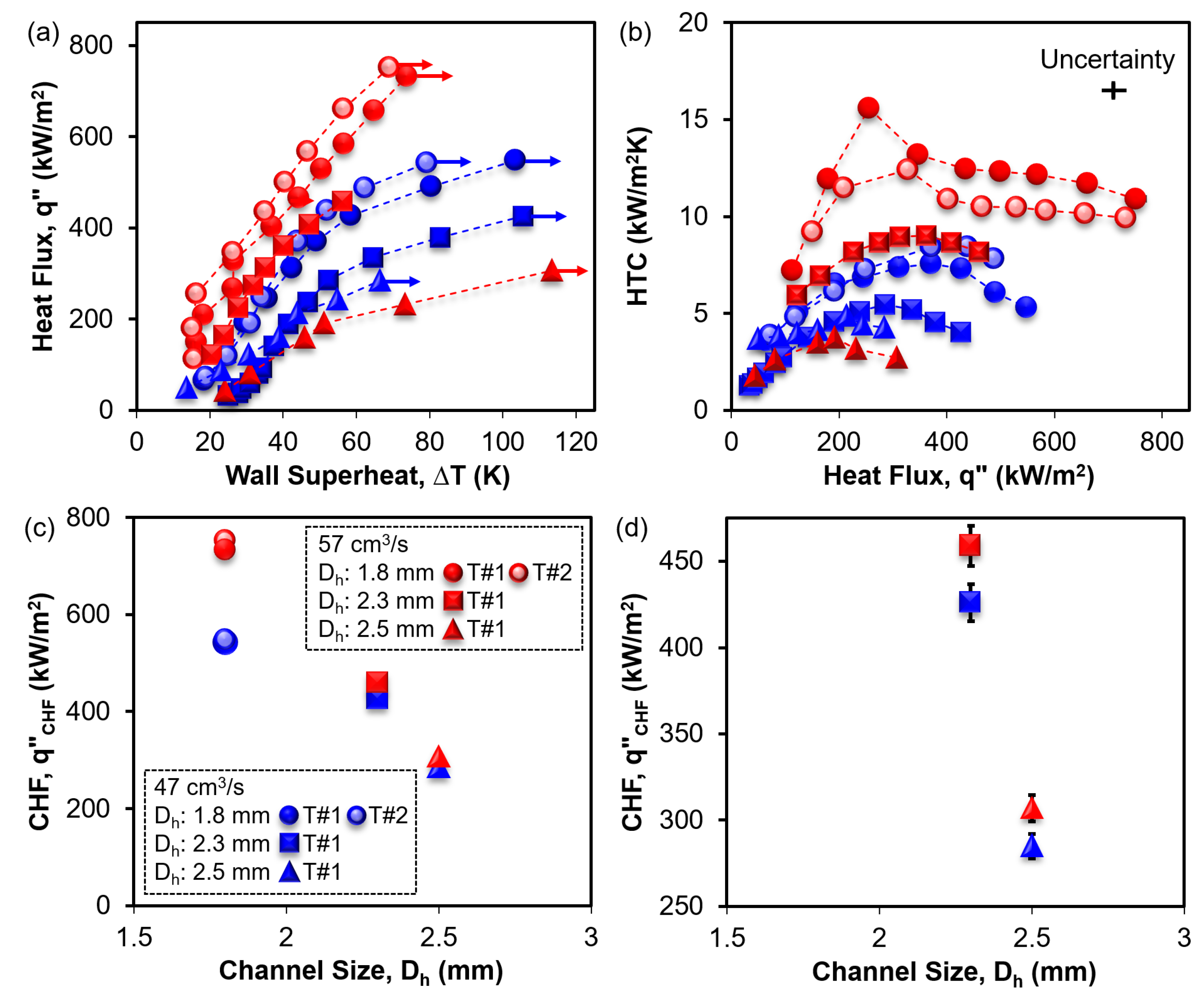
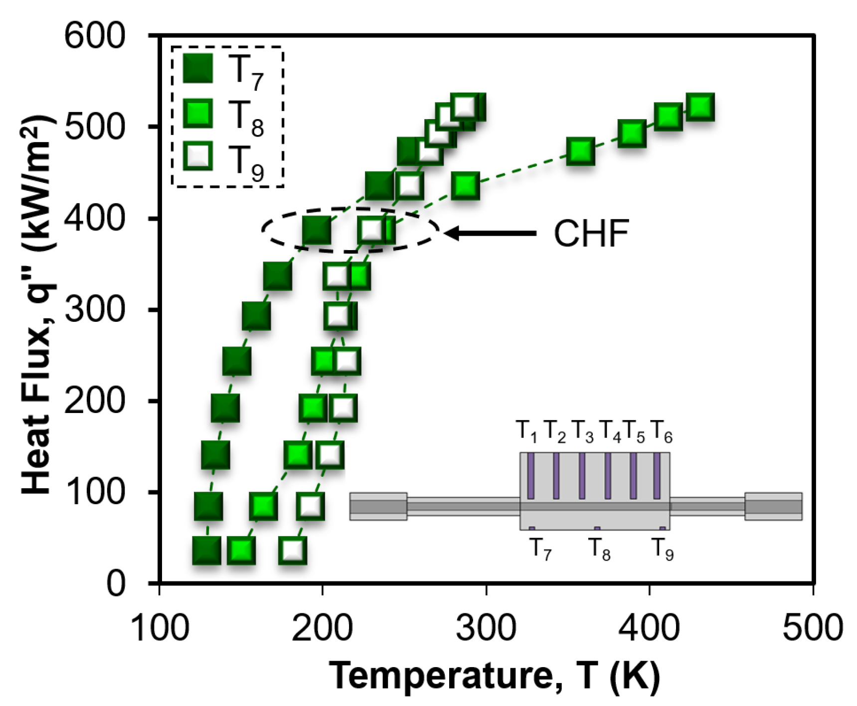
To investigate the cryogenic flow boiling in additively manufactured GR-Cop42 cooling channels, 20 tests have been performed at two different inlet pressures, two different degrees of subcooling and five different LN2 flowrates. The following sections present the boiling results showing the boiling repeatability, effect of mass flux, effect of inlet pressure and degree of subcooling, effect of channel size, and finally an experimental CHF correlation for asymmetrically heated additively manufactured LN2 cooling channels.

3.1. Repeatability

To characterize the repeatability of the flow boiling performance, the 1.8 mm hydraulic diameter channel (1.8 mm × 1.8 mm square) design has been tested several times. Figure 5 shows the repeated boiling results for two similar channels at two different LN2 flow rates of 47 cm3/s, and 57 cm3/s. X-axis represents the wall superheat, i.e., the difference between the channel average surface temperature and liquid nitrogen saturation temperature (~108.97 K) at 1.38 MPa inlet pressure. Y-axis represents the heat transfer rate per unit wetted area of the cooling channel. The arrows represent CHF point.
The red circles represent the 1.8 mm channel with 57 cm3/s LN2 flow rate, and blue circles represent the 1.8 mm channel with 47 cm3/s LN2 flow rate. The dark red and blue filled circles represent the first-time test results for the first sample (Ch#1), the shaded red and blue circles represent the repeated boiling results for the first sample, and the light red circles represent the first-time test result for the similar 1.8 mm channel (Ch#2). A maximum CHF value of 752 kW/m2 has been achieved for the channel#1 test#1 at 57 cm3/s flow rate. The second test of the same channel shows a CHF value of 732 kW/m2. However, the first test of the second channel shows a higher CHF of ~767 kW/m2. For the 47 cm3/s flow rate, the first test shows a CHF of 548 kW/m2 and the second test shows a CHF of 543 kW/m2. A shift in the boiling curves is present with a maximum variation in CHF of approximately ±1.1% for the 57 cm3/s LN2 flow tests, and approximately ±0.5% for the 47 cm3/s flow tests. This is negligible compared to the experimental uncertainty of ±2.52% for the heat flux results. However, the variation in wall superheat is significant that can be attributed to the fouling, handling of the test samples, test sample manufacturing and boiling itself [30].

3.2. Effect of Mass Flux

During flow boiling, single-phase forced convection and bubble dynamics through nucleation, growth and departure-enabled efficient heat removal from the hot surfaces. Mass flux is one of the strongest parameters that affects the flow boiling heat transfer performance through increased single-phase forced convection. At low mass flux conditions, gravity effect becomes important for horizontal channels [31]. In this work, the flow boiling tests have been performed in horizontal flow orientation. However, the calculated modified Froude number F r * = G cos θ / ρ l g D h ρ l ρ v / ρ v value varies from 12.95 to 53.77 for the flow boiling tests conducted in this work. Here, G is the LN2 mass flux (kg/m2s), ρ l is the density of liquid nitrogen and ρ v is the density of nitrogen gas at the saturation temperature of corresponding pressure. θ is the flow orientation (here, θ = 0 ), and D h is the hydraulic diameter of the cooling channels. Since the modified Froude number value is significantly greater than 6, the cryogenic liquid flow and heat transfer performance of the cooling channels tested in this work are independent of flow orientation relative to Earth’s gravity [1].
To characterize the effect of mass flow rate on LN2 flow boiling, a series of flow boiling tests have been performed at various LN2 flow rates using a 2.3 mm hydraulic diameter channel (2.3 mm × 2.3 mm) at 1.38 Mpa pressure and saturation temperature. The results are presented in Figure 6. Figure 6a shows the boiling curves at various volumetric flow rates. The orange, green, blue, and red squares represent 25 cm3/s, 38 cm3/s, 47 cm3/s, and 57 cm3/s volumetric flow rates, respectively. Solid squares represent test#1 whereas light squares represent test#2. It is evident from Figure 6a that with increasing LN2 flow rates, the boiling curves are shifted to the left in general, i.e., increasing HTC. A similar trend has also been observed by Ribatski et al. [32], Agostini et al. [33], and Wang and Sefiance [34] and it has been attributed to the transition from partial to fully developed nucleate boiling. During flow boiling, heat transfer is governed by the combination of nucleate boiling and forced convective evaporation. This can be represented by H T C = S H T C n b + F H T C c o v [35]. Here, H T C n b is the heat transfer coefficient for nucleate boiling, S is the suppression factor for nucleate boiling, H T C c o v is the heat transfer coefficient for forced convective evaporation, and F is the forced convective evaporation enhancement factor. As the liquid flow rate increases, the contribution of nucleate boiling ( S ) reduces due to the suppression of nucleation sites, and the contribution of forced convective evaporation ( F ) increases for flow boiling. Therefore, for the transition from 25 cm3/s flow rate (orange squares) to 38 cm3/s flow rate (dark green squares) in Figure 6a, HTC increases due to the enhanced contribution from forced convective evaporation ( F ) in addition to the contribution from nucleate boiling ( S ). However, with a further increase in LN2 flow rate at 47 cm3/s (dark blue squares), the boiling curve can be seen shifting to the right as compared to the 38 cm3/s flow rate (dark green squares) curve. Zhang et al. [36] have observed the collapse of boiling curves at various mass flux values in a vertical mini channel for LN2 due to the significance of nucleate boiling through the consumption of latent heat. This has also been observed in mini channels by other researchers, such as Balasubramanian et al. [37] and Bertsch et al. [38]. Furthermore, Zhang et al. [36] have shown that the HTC decreases with increasing mass flux due to the suppression of nucleate boiling in the intermediate mass flux regimes. Therefore, the HTC decreasing trend of boiling curve for the dark blue squares as compared to the dark green squares can be attributed to the suppression of augmented nucleate boiling, however, there exist the contribution from enhanced forced convective evaporation. Although the LN2 flow rate increases from 47 cm3/s to 57 cm3/s and the contribution from nucleate boiling decreases, the significant increase in the contribution from forced convective evaporation eventually increases the HTC that can be seen in the red squares in Figure 6a. It can also be seen that the second tests for 38 cm3/s flow rate (light green squares) and 47 cm3/s flow rate (light blue squares) are flipped, i.e., the second test boiling curve shifts to the right as compared to the first test for 38 cm3/s. Since heat transfer at 38 cm3/s flow rate has a significant contribution from nucleate boiling, the decreasing HTC in the second test can be attributed to the reduction in entrapped non-condensable gases that facilitates the nucleation on boiling surface [39] and aging phenomena [40].
The effect of mass flux on CHF ( q C H F ) is presented in Figure 6b where mass flux is calculated from measured volumetric flow rates using Equation (6). A maximum CHF of 459 kW/m2 has been achieved for the 57 cm3/s flow rate. The CHF for 47 cm3/s flow rate is 426 kW/m2 and 38 cm3/s flow rate tests show a variation in CHF of 387 kW/m2 and 401 kW/m2 between repeated tests. CHF value of 337 kW/m2 has been achieved for the 25 cm3/s flow rate which is the minimum among all four flow rates. The results show that CHF increases in a linear trend as the mass flux increases, which has also been reported by Agostini et al. [41], Roday et al. [42], and Ong and Thome [43]. However, the opposite trend has also been observed by other researchers. Qi et al. [44] and Callizo [45] have shown that CHF decreases with increasing mass flux due to the shear-enhanced droplet entrainment effect in vertical channels. However, for horizontal channels, the droplet entrainment effect reduces the flow instability with increasing mass flux [31]. Therefore, the CHF enhancement can be attributed to the reducing influence of flow instability and gravity effects with increasing LN2 mass flux resulting in an increased forced convective evaporation in this work.

3.3. Effect of Inlet Pressure and Subcooling

Figure 7 presents the effect of inlet pressure and degree of subcooling on LN2 flow boiling tests in cooling channels. The purple color represents the mass flow rate of 31 cm3/s. Circles represent the 1.8 mm hydraulic diameter channel and triangular dots represent the 2.5 mm hydraulic diameter channel. Dark solid purple markers represent boiling results for 1.38 MPa inlet pressure and saturation temperature (test#1), light purple markers represent results for 1.38 MPa inlet pressure and saturation temperature (test#2), open purple represent results from 1.59 MPa inlet pressure and saturation temperature, and cyan filled purple represent boiling results for 1.59 MPa inlet pressure and 5 degrees of subcooling. Figure 7a presents the boiling heat flux up to CHF in Y-axis as a function of channel average wall superheat in X-axis. Figure 7b presents the CHF (Y-axis) as a function of inlet pressure (X-axis) at various degrees of subcooling. It is evident from Figure 7 that for both channels CHF decreases with increasing pressure. The 1.8 mm channel shows a CHF value of ~468 kW/m2 at 1.38 MPa pressure and zero-degree subcooling. The CHF value decreases to 407 kW/m2 at 1.59 MPa pressure and corresponding saturation temperature. This represents an approximately 13% reduction in CHF with the increase in pressure. Similarly, the 2.5 mm channel shows the CHF values of 221 kW/m2 and 218 kW/m2 between the two tests at 1.38 MPa pressure and saturation temperature. However, the CHF value decreases to 188 kW/m2 at 1.59 MPa pressure, representing approximately 14% decrease in CHF. Therefore, it is evident that both channels show a similar reduction in CHF with a similar increase in operating pressure. Finally, it can be seen from Figure 7b that by increasing the pressure from 1.38 MPa to 1.59 MPa and decreasing the inlet fluid temperature (saturation to 5 degree of subcooling), the 1.8 mm channel achieves a CHF of 474 kW/m2, highlighted by the arrow. This is comparable to the boiling CHF of 468 kW/m2 at 1.38 MPa pressure and saturation temperature. However, Figure 7a shows a significant shift of the boiling curve to the left, representing HTC increase for the sub-cooled boiling of 1.8 mm channel as compared to the saturation boiling.
The effect of pressure on internal forced convective boiling is complex due to the integrated influence of liquid and vapor density of the fluid, surface tension, flow orientation and gravity. Wu et al. [46] have shown that CHF increases with increasing pressure for water flow boiling in vertical annular mini channels. They have attributed this enhancement to the reduction in the ratio of liquid and vapor density, corresponding velocity ratio, and droplet entrainment effect. Donniacuo et al. [47] have reached the same conclusion for 3 mm diameter horizontal channels and attributed the enhancement to the increase in liquid film thickness and influence of gravity. On the contrary, Charnay et al. [48,49] have presented that high pressure leads to increase in liquid film thickness and decrease in vapor quality resulting in a decrease in CHF. Furthermore, Zhang et al. [36] have shown that heat transfer deteriorates with increasing inlet pressure due to the reduction in surface tension resulting in the earlier appearance of an unsteady annular flow regime. Additionally, the standard thermophysical properties of LN2 shows that the latent heat of vaporization also decreases with increasing operating pressure, and phase change heat transfer is a strong function of the latent heat of vaporization. Therefore, the decrease in CHF with increasing pressure in this work can be attributed to the reduction in surface tension and latent heat of vaporization of LN2. However, the increase in CHF with increasing degree of subcooling, as shown in Figure 7b, is well-established in the literature. Celata et al. [50], Vandervort et al. [51], and Inasaka and Nariai [52] have observed an increase in CHF with increasing the degree of subcooling that is consistent with the result presented in this work. Moreover, Bao et al. [53] and Qi et al. [44] have shown that with the increase in pressure, bubble size becomes smaller and bubble departure frequency increases leading to an increase in heat transfer coefficient. Therefore, the shift in boiling curve for the 1.8 mm channel at 1.38 MPa pressure and 5-degree subcooling can be attributed to the bubble size reduction and bubble departure frequency enhancement.

3.4. Effect of Channel Size

The effect of channel size on LN2 flow boiling heat transfer is presented in Figure 8. Figure 8a presents the boiling curves of CHF for all three channels (1.8 mm, 2.3 mm, and 2.5 mm hydraulic diameter channels) at 57 cm3/s and 47 cm3/s flow rates, 1.38 MPa pressure and corresponding saturation temperature. Figure 8b presents the heat transfer coefficient (HTC) as a function of heat flux for the results from Figure 8a. The circles represent the 1.8 mm channel, squares represent the 2.3 mm channel and triangles represent the 2.5 mm channel. Red color represents the boiling results for 57 cm3/s flow rate, and blue color represents the boiling results for 47 cm3/s flow rate. Dark fill color represents the first test and light fill color represents the second test for the same channel. It is evident from the results that the boiling curves shift to the left with decreasing channel size. Figure 8b shows the HTC enhancement with decreasing channel size (triangle to square to circle) as well as increasing mass flow rate (blue to red markers).
Since the flow boiling heat transfer varies significantly from small channels to micro-channels due to the influence of surface tension, time-dependent flow patterns, and bubble dynamics [31,54], it is therefore essential to first identify the classification of cooling channels utilized in this work. According to Kandlikar and Grande [54], channels are classified into seven different types based on the hydraulic diameter: conventional channels ( D h > 3   mm ), minichannels ( 200   μ m < D h   3   mm ), microchannels ( 10   μ m < D h   200   μ m ), transitional microchannels ( 1   μ m < D h   10   μ m ), transitional nanochannels (0.1   μ m < D h   1   μ m ), and molecular nanochannels ( D h   0.1   μ m ). In this work, the smallest channel hydraulic diameter is 1.8 mm, and the largest channel hydraulic diameter is 2.5 mm. Therefore, the channels used in this work are considered minichannels.
For minichannels, two mechanisms dominate the flow boiling heat transfer: nucleate boiling and forced convective evaporation [55]. The heat transfer coefficient is affected by the heat flux where nucleate boiling is dominant. Tran et al. [56] have shown that HTC increases with increasing heat flux but is independent of mass flux and vapor quality for 2.4 mm square and 2.46 mm circular channels using R12 as the working fluid. This is typical where nucleate boiling is dominant, and HTC is affected by the heat flux [57,58]. However, HTC is affected by the mass flux and vapor quality where the forced convective evaporation is dominant [55]. The thermodynamic exit vapor quality at CHF, calculated from Q / ρ l ˙ h l v , where h l v is the latent heat of vaporization, varies approximately from 0.024 to 0.069. Therefore, the influence of vapor exit quality on HTC can be considered insignificant for this work. Indeed, it can be seen from Figure 8a,b that the high aspect ratio 2.5 mm channel does not show a major difference in HTC with increasing mass flux. This is inverse from the observation reported by Wang et al. [34] that can be attributed to the low aspect ratio (AR~2.27) channel utilized in this work as compared to their high aspect ratio channels (AR~10 and 20). However, it is evident from Figure 8b that increasing mass flux (blue to red) significantly increases the HTC for the 1.8 mm channel (circle) and 2.3 mm channel (square). Therefore, it can be implied that the high aspect ratio 2.5 mm channel (1.8 mm × 4.1 mm) exhibits nucleate boiling dominating HTC trend, and that both the 1.8 mm and 2.3 mm channels exhibit the forced convective evaporation dominating HTC enhancement. Furthermore, the boiling results in Figure 8b show that average heat transfer coefficient initially increases and then decreases with increasing heat flux. Wang et al. [34] have attributed this heat transfer deterioration phenomenon to partial or intermittent dry-out. Additionally, for a given mass flux, HTC has been observed to increase with decreasing channel diameter. This increase can be attributed to the decrease in liquid film thickness on the channel walls that increases the contribution of liquid film evaporation for flow boiling heat transfer.
The effect of channel size on CHF is presented in Figure 8c. Due to the high range of CHF values, specifically for the 1.8 mm channel, CHF as a function of channel size for 2.3 mm and 2.5 mm channels is separately presented in Figure 8d with error bars showing the variation in CHF with mass flux. It is clear from Figure 8c,d that CHF increases (307 kW/m2 to 752 kW/m2) with decreasing channel size (2.5 mm to 1.8 mm, respectively) and increasing mass flux (548 kw/m2 at 47 cm3/s to 752 kW/m2 at 57 cm3/s for 1.8 mm channel) in a non-linear fashion. The increasing trend of CHF with decreasing channel diameter is consistent with other researchers, such as Ong and Thome [43], Vandervort et al. [51], and Celata et al. [59]. However, a variation in observations also exists in the literature. Qi et al. [44] have performed LN2 flow boiling in 0.531 mm, 0.834 mm, 1.042 mm, and 1.931 mm channels and shown that CHF increases with increasing tube diameter. They have attributed this CHF enhancement to the appearance of nucleate boiling. Vandervort et al. [51] have performed sub-cooled flow boiling of water in 0.3 to 2.7 mm tubes up to 40,000 kg/m2s mass flux and observed that CHF increases up to the length-to-diameter ratio of 10. Moreover, Celata et al. [59] have identified a threshold ratio up to 30. The length-to-diameter ratios are 20, 22, and 27 in this work, showing a consistent CHF enhancement above the length-to-diameter ratio of 10 and below 30. Ong and Thome [43] have also shown that CHF values for R134a reach peak value up to a threshold diameter lying between the Confinement number (Co) of 0.78–0.99 for 0.51 mm to 3.04 mm channels. The confinement number (Co) varies from 0.25 to 0.37 in this work, calculated by σ / g ρ l ρ v D h 2 , where σ is the surface tension, and g is the gravitational acceleration. Since Co is inversely proportional to channel size, a decrease in channel size below 1.8 mm appears to increase CHF up to the threshold diameter (up to Co~0.99) of approximately 0.73 mm at 1.38 MPa pressure and saturation temperature. This increase in CHF with decreasing channel size can be attributed to the increase in the contribution of forced convective evaporation associated with the high mass flow rates and explained through hydrodynamic boundary conditions [44].

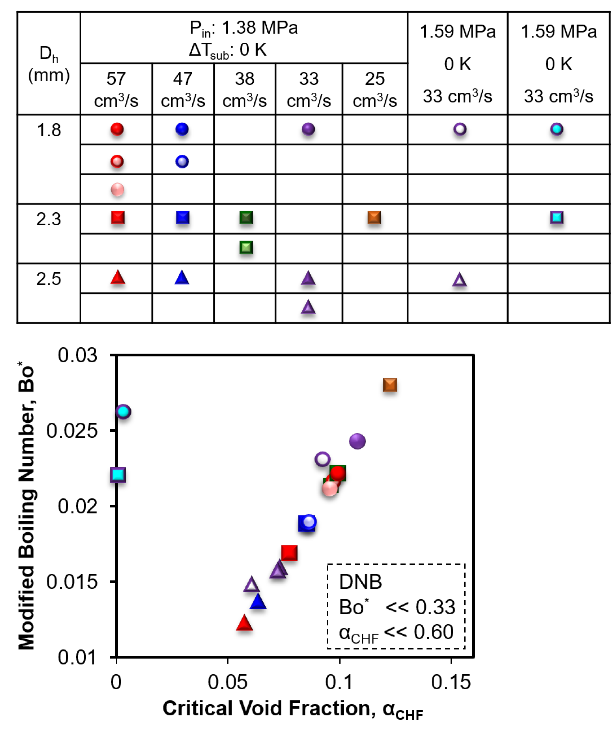
3.5. CHF Correlation

Two types of CHF are encountered in cooling channel flow boiling susceptible to the degree of subcooling, mass flux and wall heat flux. Dry-out type CHF is associated with the complete evaporation of the liquid film from the heated wall at low mass flux and low degree of subcooling, and high critical length-to-diameter ratios. On the contrary, departure from nucleate boiling (DNB) type CHF is encountered when a vapor blanket is formed on the heated wall despite the availability of abundant liquid core at high mass flow rates, high degrees of subcooling, and high heat flux values. A significant number of correlations have been proposed by researchers, such as Katto and Kurata, 1980 [60], Katto and Ohno, 1984 [61], Katto and Yokoya, 1987 [62], Shah, 1987 [63], Mudawar and Maddox, 1990 [64], Hall and Mudwar, 2000 [65], Darr, 2019 [66], and Ganesan, 2021 [1], aiming to enable accurate prediction of flow boiling CHF. However, the correlations are strongly dependent on the CHF type as the two-phase flow physics and CHF fundamental mechanisms are significantly different. Therefore, it is imperative to segregate the CHF type for utilizing the appropriate correlation and comparing the test results from this work.
According to Ganesan et al. [1], there exist threshold values of critical void fraction ( α C H F < 0.6 for LN2) and modified Boiling number ( B o * < 0.33 for LN2) that demarcate DNB-type CHF from dry-out type CHF. The critical void fraction has been calculated using Zivi’s correlation [67] given by Equation (10).
α C H F = 1 + 1 x e , C H F x e , C H F ρ l ρ v 2 / 3 1
Here, x e , C H F is the thermodynamic equilibrium quality at the CHF location [1] that has been calculated using Equation (11). Boiling number is defined as B o = q C H F / G h l v , where L C H F is the axial location where CHF occurs.
x e , C H F = x e , i n + 4 B o L C H F D h
In this work, L C H F is considered as half of the heated length, i.e., 2.5 cm. The occurrence of CHF near the middle of the asymmetrically heated cooling channel can be observed from the temperature distribution underneath the channel. Figure 9 shows an example of the temperature profile in the bottom three thermocouples (T7–T9) for the 2.3 mm channel at 38 cm3/s flow rate, 1.38 MPa inlet pressure and saturation temperature. The Y-axis represents the average heat flux and X-axis represents the surface temperature. It is evident from Figure 9 that at CHF~387 kW/m2 the middle thermocouple (T8) underneath the channel wall shows a significant increase in temperature as compared to the thermocouples near the inlet and exit of the cooling channel. Therefore, half of the heated length has been considered as the CHF length from the channel inlet.
The modified Boiling number ( B o * ) has been calculated from Equation (12). Here, x e , i n is the thermodynamic equilibrium quality at the channel inlet defined by x e , i n = h i n h l , i n / h l v , i n , where h i n is the enthalpy of fluid at inlet temperature, h l , i n is the enthalpy of saturated liquid at inlet pressure, and h l v , i n is the latent heat of vaporization at the inlet pressure.
B o * = 4 B o L C H F D h 1 x e , i n
The modified Boiling number as a function of critical void fraction for all three channels, five different flow rates, two different pressures, and two degrees of subcooling is presented in Figure 10. As can be seen, the maximum modified Boiling number encountered in this work is ~0.028 which is much smaller than the threshold modified Boiling number ( B o * 0.33 ) for LN2 DNB-type CHF. Additionally, the maximum critical void fraction encountered in this work is ~0.12, which is also much smaller than the threshold critical void fraction ( α C H F 0.6 ) for LN2 DNB-type CHF. Therefore, it can be postulated that the critical heat flux values associated with this work are DNB-type CHF which is consistent with the literature at high mass flow rates and high heat flux conditions.
Although a significant number of CHF correlations are available for flow boiling in cooling channels, a close inspection will reveal that there exists a lack of errorfree, reliable, and simple universal CHF correlation for cryogenic fluids. Recently, Ganesan et al. [1] have proposed a universal CHF correlation for the flow boiling of cryogenic liquids, more specifically for liquid hydrogen, liquid helium, liquid nitrogen, and liquid methane by amassing 2312 CHF data points. The proposed experimental correlations have been shown to work for both horizontal and vertical orientation of flow, and for both DNB and dry-out type CHF. Therefore, this work compares the experimental CHF results with the correlation presented in Ganesan et al. [1]. Equation (13) has been used to predict the CHF values ( q C H F , P ) for all three cooling channels, five different LN2 flow rates, two different inlet pressures and two different degrees of subcooling. Here, Weber number ( W e l , D ) is based on channel hydraulic diameter and has been calculated from W e l , D = G 2 D h / ρ l σ , where σ is the liquid–vapor surface tension at the saturation condition. Since this work presents the CHF results for horizontal flow and DNB-type CHF, therefore, the constant values are considered as c 1 = 0.32 , c 2 = 0.24 , c 3 = 0.60 , c 4 = 0.48 , and c 5 = 0.69 .
q C H F , P = 0.25   c 1 W e l , D c 2 ρ v ρ l c 3 1 x e , i n c 4 + 1 L C H F D h c 5 1 G   h l v
The LN2 CHF results from this work are compared with the literature correlation in Figure 11 where all the legends are held the same as in Figure 10. Y-axis represents the predicted CHF and X-axis represents the measured CHF results. Here, the MAE and RMS are calculated using Equations (14) and (15), respectively. q C H F , P G is the predicted CHF using Ganesan et al.’s [1] universal correlation, q C H F , P is the predicted CHF in this work and q C H F , m is the experimentally measured CHF in this work.
M A E = 1 N q C H F , P q C H F , m q C H F , m × 100 %
R M S = 1 N q C H F , P q C H F , m q C H F , m 2 1 / 2 × 100 %
It is evident from the comparison in Figure 11 that the model overpredicts the DNB results with 56.39% mean absolute error (MAE) and 66.77% root mean squared (RMS) error. Additionally, the percentage of CHF result prediction within ±30% (θ) is 45% and within ±50% (ξ) is 85%. This overprediction can be attributed to the asymmetrically heated non-circular cooling channels tested in this work where Ganesan et al.’s [1] universal correlation has been developed for the uniformly heated tubes. Moreover, the development of analytical models and computational fluid dynamics (CFD) models require intense parametric tests using flow measurement and visualization for validation which is limited for cryogenic experiments. As such, there exists a pressing need to develop an experimental correlation for asymmetrically heated non-circular cooling channels. To develop the correlation for LN2 flow boiling in asymmetrically heated non-circular channels in this work, the generalized reduced gradient (GRG) solver in Microsoft Excel has been used to identify the constant factors for Equation (13). The calculated values are as follows: c 1 = 0.0015 , c 2 = 0.17 , c 3 = 0.38 , c 4 = 1.09 , and c 5 = 1.43 . Utilizing these curve fitting parameters in Equation (13), the CHF values have been calculated for all the 20 test conditions and are compared with the experimental CHF results in Figure 12. As seen from the comparison, the new correlation predicts the LN2 DNB results with 10.68% mean absolute error (MAE) and 12.67% root mean squared (RMS) error. Additionally, the percentage of CHF result prediction within ±30% (θ) is 100%.
However, the new correlation is developed based on the experimental database presented in this work due to the lack of literature on cryogenic flow boiling in asymmetrically heated non-circular cooling channels at high mass flux and pressure values. Moreover, the present work has focused only on additively manufactured channels and LN2 as the working fluid. Therefore, it is essential to perform a parametric study on the effect of influential parameters including a wide range of hydraulic diameters (micro- to macro-channels), mass flow rates, pressures and corresponding saturation temperatures, degrees of subcooling, vapor quality, channel materials [68], micro/nano-scale structures [69], conventional channels, and various cryogenic fluids, such as LCH4, LH2 and LHe, to develop a universal correlation for regenerative cooling channels.

4. Conclusions

Additively manufactured asymmetrically heated non-circular channels have been shown to suggest a new DNB correlation for LN2 flow boiling. Three different GR-Cop42 channels have been tested at five different flow rates, two inlet pressures and two degrees of subcooling. The repeatability of flow boiling performance has been conducted using the 1.8 mm × 1.8 mm cooling channel showing a maximum CHF variation of ±1.1% at 57 cm3/s and ±0.5% at 47 cm3/s LN2 flow tests which are significantly lower than the measurement uncertainty of ±2.52%. The effect of LN2 flow rate on flow boiling HTC and CHF has been characterized using a 2.3 mm × 2.3 mm channel (2.3 mm hydraulic diameter). HTC enhancement has been observed with increasing mass flux in general for the tested range of 3824 kg/m2s to 8605 kg/m2s. An increase in HTC has been observed with increasing the mass flow rate from 25 cm3/s to 38 cm3/s due to the contribution of enhanced nucleate boiling. However, with the increase in LN2 flow rate to 47 cm3/s, HTC has been observed to decrease which is attributed to the suppression of nucleate boiling. A further increase in flow rate to 57 cm3/s, and the significant contribution from forced convective evaporation achieved a significant increase in HTC. However, CHF has been observed to increase linearly as the mass flux increases due to the reducing influence of flow instability and gravitation effect and increasing forced convective evaporation. CHF values of 337 kW/m2 and 459 kW/m2 have been achieved at 25 cm3/s and 57 cm3/s LN2 flow rates for the 2.3 mm channel, respectively.
The effect of system pressure on CHF and HTC has been evaluated for the 1.8 mm × 1.8 mm (1.8 mm hydraulic diameter) and 1.8 mm × 4.1 mm (2.5 mm hydraulic diameter) channels at 1.38 MPa and 1.59 MPa pressures, respectively. Increasing system pressure has shown to negatively affect CHF due to the decrease in surface tension and latent heat of vaporization of LN2. CHF values have been observed to decrease by 13% for the 1.8 mm channel and 14% for the 2.5 mm channel with the increase in system pressure. However, HTC has been seen to increase with increasing pressure, which is attributed to the reducing bubble size and increasing bubble departure frequency. Moreover, among the three different channels, enhancements in both HTC and CHF have been achieved with decreasing channel size. The experimental results show that CHF increases from 307 kW/m2 to 752 kW/m2 with decreasing channel size from 2.5 mm to 1.8 mm, respectively, in a non-linear fashion due to the significant enhancement in the contribution of forced convective evaporation. CHF enhancement from 548 kw/m2 to 752 kW/m2 has also been observed for the 1.8 mm channel with the increasing LN2 flow rate from 47 cm3/s to 57 cm3/s.
Through the comparison of modified boiling number and critical void fraction, this work shows the DNB-type CHF for minichannels at high mass flux values and high inlet pressures during LN2 flow boiling. Finally, it has been found that the literature universal DNB model for uniformly heated tubes overpredicts the DNB heat flux for asymmetrically heated non-circular cooling channels with 56.39% mean absolute error (MAE) and 66.77% root mean squared (RMS) error. Therefore, a new modified DNB correlation for LN2 has been developed in this work with 10.68% MAE, 12.67% RMS error, and 100% prediction capability within ±30% uncertainty. This work aims to provide a fundamental cryogenic flow boiling heat transfer performance of additively manufactured asymmetrically heated non-circular minichannels at high mass flux values and pressures and bridge the gaps in the literature for high-performance regeneratively cooled rocket engines.

Author Contributions

Conceptualization, M.M.R. and A.C.; methodology, M.M.R. and D.O.; software, D.O. and A.A.; validation, D.O. and A.A.; formal analysis, D.O., M.M.R. and M.A.; investigation, D.O. and A.A.; resources, A.C. and M.M.R.; data curation, D.O., A.A. and M.M.R.; writing—original draft preparation, D.O. and M.M.R.; writing—review and editing, M.A., A.A. and A.C.; visualization, D.O.; supervision, M.M.R.; project administration, M.M.R. and A.C.; funding acquisition, M.M.R. and A.C. All authors have read and agreed to the published version of the manuscript.

Funding

This research was funded by the National Aeronautics and Space Administration (NASA) under Cooperative Agreement number 80NSSC19P1100 Mod. #P00005 and under NASA MIRO Cooperative Agreement number 80NSSC20M0237.

Data Availability Statement

Source data and other raw data are available from the corresponding author upon request.

Conflicts of Interest

The authors declare no conflict of interest.

References

  1. Ganesan, V.; Patel, R.; Hartwig, J.; Mudawar, I. Universal Critical Heat Flux (CHF) Correlations for Cryogenic Flow Boiling in Uniformly Heated Tubes. Int. J. Heat Mass Transf. 2021, 166, 120678. [Google Scholar] [CrossRef]
  2. Gubaidullin, D.A.; Snigerev, B.A. Numerical Simulation of Heat Transfer During Boiling Flow of Cryogenic Fluid in Vertical Tube. Lobachevskii J. Math. 2020, 41, 1210–1215. [Google Scholar] [CrossRef]
  3. Kwon, D.W.; Sedwick, R.J. Cryogenic heat pipe for cooling high temperature superconductors. Cryogenics 2009, 49, 514–523. [Google Scholar] [CrossRef]
  4. Marcushamer, M.; King, D.L.; Ruano, N.S. Cryosurgery in the management of mucoceles in children. Pediatr. Dent. 1997, 19, 292–293. [Google Scholar]
  5. Yuan, K. Cryogenic Boiling and Two-Phase Chilldown Process Under Terrestrial and Microgravity Conditions. Ph.D. Thesis, University of Florida, Gainesville, FL, USA, 2006. [Google Scholar]
  6. Zhou, C.; Yu, N.; Wang, S.; Han, S.; Gong, H.; Cai, G.; Wang, J. The Influence of Thrust Chamber Structure Parameters on Regenerative Cooling Effect with Hydrogen Peroxide as Coolant in Liquid Rocket Engines. Aerospace 2023, 10, 65. [Google Scholar] [CrossRef]
  7. Ferraiuolo, M.; Leo, M.; Citarella, R. On the Adoption of Global/Local Approaches for the Thermomechanical Analysis and Design of Liquid Rocket Engines. Appl. Sci. 2020, 10, 7664. [Google Scholar] [CrossRef]
  8. Cho, W.K.; Seol, W.S.; Son, M.; Seo, M.K.; Koo, J. Development of preliminary design program for combustor of regenerative cooled liquid rocket engine. J. Therm. Sci. 2011, 20, 467–473. [Google Scholar] [CrossRef]
  9. Van Huff, N.E.; Fairchild, D.A. Liquid Rocket Engine Fluid-Cooled Combustion Chambers; NASA Lewis Research Center: Cleveland, OH, USA, 1972.
  10. Sutton, G.P.; Biblarz, O. Rocket Propulsion Elements, 9th ed.; John Wiley & Sons Inc.: Hoboken, NJ, USA, 2017. [Google Scholar]
  11. Boysan, M.E.; Ulas, A.; Toker, K.A.; Seckin, B. Comparison of Different Aspect Ratio Cooling Channel Designs for a Liquid Propellant Rocket Engine. In Proceedings of the 2007 3rd International Conference on Recent Advances in Space Technologies, Istanbul, Turkey, 14–16 June 2007. [Google Scholar]
  12. Wang, T.-S.; Luong, V. Hot-gas-side and coolant-side heat transfer in liquid rocket engine combustors. J. Thermophys. Heat Transf. 1994, 8, 524–530. [Google Scholar] [CrossRef]
  13. Celata, G.P.; Mariani, A. Critical Heat Flux, Post Dry-Out and Their Augmentation; ENEA-RT-ERG-98-10; ENEA: Rome, Italy, 1999. [Google Scholar]
  14. Wadel, M. Comparison of high aspect ratio cooling channel designs for a rocket combustion chamber. In Proceedings of the 33rd Joint Propulsion Conference and Exhibit, Joint Propulsion Conferences, Seattle, WA, USA, 6–9 July 1997; American Institute of Aeronautics and Astronautics: Reston, VA, USA, 1998. [Google Scholar]
  15. Van Noord, J.L.; Center, N.G.R.; Meeting, J.P. A Heat Transfer Investigation of Liquid and Two-Phase Methane; National Aeronautics and Space Administration, Glenn Research Center: Cleveland, OH, USA, 2010.
  16. Huzel, D.K.; Huang, D.H. Design of Liquid Propellant Rocket Engines, 2nd ed.; Scientific and Technical Information Office, National Aeronautics and Space Administration: Washington, DC, USA, 1967.
  17. Pizzarelli, M. Modeling of Cooling Channel Flow in Liquid-Propellant Rocket Engines. Ph.D. Thesis, University of Rome, Rome, Italy, 2007. [Google Scholar]
  18. Denies, L. Regenerative Cooling Analysis of Oxygen/Methane Rocket Engines. Master’s Thesis, TU Delft, Mekelweg, The Netherlands, 2015. [Google Scholar]
  19. Waxenegger-Wilfing, G.; Dresia, K.; Deeken, J.C.; Oschwald, M. Heat Transfer Prediction for Methane in Regenerative Cooling Channels with Neural Networks. J. Thermophys. Heat Transf. 2020, 34, 347–357. [Google Scholar] [CrossRef]
  20. Song, J.; Liang, T.; Li, Q.; Cheng, P.; Zhang, D.; Cui, P.; Sun, J. Study on the heat transfer characteristics of regenerative cooling for LOX/LCH4 variable thrust rocket engine. Case Stud. Therm. Eng. 2021, 28, 101664. [Google Scholar] [CrossRef]
  21. Santhosh, T.; Kuzhiveli, B.T. Heat transfer aspects and analysis of regenerative cooling in semi-cryogenic thrust chamber with fixed and variable aspect ratio coolant channels. In Proceedings of the IOP Conference Series: Materials Science and Engineering, Kazimierz Dolny, Poland, 21–23 November 2019. [Google Scholar]
  22. Wadel, M.; Meyer, M. Validation of high aspect ratio cooling in a 89 kN (20,000 lbf) thrust combustion chamber. In Proceedings of the 32nd Joint Propulsion Conference and Exhibit, Lake Buena Vista, FL, USA, 1–3 July 1996; American Institute of Aeronautics and Astronautics: Reston, VA, USA, 1996. [Google Scholar]
  23. Carlile, J.; Quentmeyer, R. An experimental investigation of high-aspect-ratio cooling passages. In Proceedings of the 28th Joint Propulsion Conference and Exhibit, Nashville, TN, USA, 6–8 July 1992; American Institute of Aeronautics and Astronautics: Reston, VA, USA, 2012. [Google Scholar]
  24. Ellis, D. GRCop-84: A High-Temperature Copper Alloy for High-Heat-Flux Applications; NASA Glenn Research Center: Cleveland, OH, USA, 2005.
  25. Gradl, P.R.; Protz, C.S.; Cooper, K.; Ellis, D.; Evans, L.J.; Garcia, C. GRCop-42 Development and Hot-fire Testing Using Additive Manufacturing Powder Bed Fusion for Channel-cooled Combustion Chambers. In Proceedings of the AIAA Propulsion and Energy 2019 Forum, Indianapolis, IN, USA, 19–22 August 2019; American Institute of Aeronautics and Astronautics: Reston, VA, USA, 2019. [Google Scholar]
  26. Ortega, D.; Amador, A.; Silva, A.; Choudhuri, A.R.; Rahman, M.M. Effect of Pressure on Liquid Nitrogen Flow Boiling in Additively Manufactured Rocket Engine Cooling Channels. In Proceedings of the AIAA SciTech Forum, National Harbor, MD, USA, 23–27 January 2023; American Institute of Aeronautics and Astronautics: Reston, VA, USA, 2023. [Google Scholar]
  27. Ortega, D.J.; Amador, A.; Choudhuri, A.R.; Rahman, M.M. Experimental Characterization of Critical Heat Flux and Minimum Film Boiling Heat Flux for Additively Manufactured Cooling Channels for Liquid Nitrogen Saturated Flow Boiling. In Proceedings of the ASME International Mechanical Engineering Congress, and Exposition, Columbus, OH, USA, 30 October–3 November 2022. [Google Scholar]
  28. Hernandez, L.; Palacios, R.; Ortega, D.; Adams, J.; Bugarin, L.I.; Rahman, M.D.M.; Choudhuri, A.R. The Effect of Surface Roughness on LCH4 Boiling Heat Transfer Performance of Conventionally and Additively Manufactured Rocket Engine Regenerative Cooling Channels. In Proceedings of the AIAA Propulsion and Energy 2019 Forum, Indianapolis, IN, USA, 19–22 August 2019; American Institute of Aeronautics and Astronautics: Reston, VA, USA, 2019. [Google Scholar]
  29. Moffat, R.J. Describing the uncertainties in experimental results. Exp. Therm. Fluid Sci. 1988, 1, 3–17. [Google Scholar] [CrossRef]
  30. Rahman, M.M.; Ölçeroğlu, E.; McCarthy, M. Scalable Nanomanufacturing of Virus-templated Coatings for Enhanced Boiling. Adv. Mater. Interfaces 2014, 1, 1300107. [Google Scholar] [CrossRef]
  31. Liu, X.; Chen, X.; Zhang, Q.; Wang, S.; Hou, Y.; Chen, L. Investigation on CHF of saturated liquid nitrogen flow boiling in a horizontal small channel. Appl. Therm. Eng. 2017, 125, 1025–1036. [Google Scholar] [CrossRef]
  32. Ribatski, G.; Wojtan, L.; Thome, J.R. An analysis of experimental data and prediction methods for two-phase frictional pressure drop and flow boiling heat transfer in micro-scale channels. Exp. Therm. Fluid Sci. 2006, 31, 1–19. [Google Scholar] [CrossRef]
  33. Agostini, B.; Thome, J.R.; Fabbri, M.; Michel, B.; Calmi, D.; Kloter, U. High heat flux flow boiling in silicon multi-microchannels—Part I: Heat transfer characteristics of refrigerant R236fa. Int. J. Heat Mass Transf. 2008, 51, 5400–5414. [Google Scholar] [CrossRef]
  34. Wang, Y.; Sefiane, K. Effects of heat flux, vapour quality, channel hydraulic diameter on flow boiling heat transfer in variable aspect ratio micro-channels using transparent heating. Int. J. Heat Mass Transf. 2012, 55, 2235–2243. [Google Scholar] [CrossRef]
  35. Lim, T.W.; Kim, J.H. An experimental investigation of heat transfer in forced convective boiling of R134a, R123 and R134a/R123 in a horizontal tube. KSME Int. J. 2004, 18, 513–525. [Google Scholar] [CrossRef]
  36. Zhang, B.C.; Li, Q.; Wang, Y.; Zhang, J.Q.; Song, J.; Zhuang, F.C. Experimental investigation of nitrogen flow boiling heat transfer in a single mini channel. J. Zhejiang Univ. Sci. A 2020, 21, 147–166. [Google Scholar] [CrossRef]
  37. Balasubramanian, K.; Lee, P.S.; Jin, L.W.; Chou, S.K.; Teo, C.J.; Gao, S. Experimental investigations of flow boiling heat transfer and pressure drop in straight and expanding microchannels—A comparative study. Int. J. Therm. Sci. 2011, 50, 2413–2421. [Google Scholar] [CrossRef]
  38. Bertsch, S.S.; Groll, E.A.; Garimella, S.V. Refrigerant flow boiling heat transfer in parallel microchannels as a function of local vapor quality. Int. J. Heat Mass Transf. 2008, 51, 4775–4787. [Google Scholar] [CrossRef]
  39. Može, M. Effect of boiling-induced aging on pool boiling heat transfer performance of untreated and laser-textured copper surfaces. Appl. Therm. Eng. 2020, 181, 116025. [Google Scholar] [CrossRef]
  40. Ramakrishnan, L.R.; Jayaramu, P.; Gedupudi, S.; Das, S. Experimental investigation of the influence of boiling-induced ageing on high heat flux flow boiling in a copper microchannel. Int. J. Heat Mass Transf. 2021, 181, 121862. [Google Scholar]
  41. Agostini, B.; Revellin, R.; Thome, J.R.; Fabbri, M.; Michel, B.; Calmi, D.; Kloter, U. High heat flux flow boiling in silicon multi-microchannels—Part III: Saturated critical heat flux of R236fa and two-phase pressure drops. Int. J. Heat Mass Transf. 2008, 51, 5426–5442. [Google Scholar] [CrossRef]
  42. Roday, A.P.; Borca-Tasçiuc, T.; Jensen, M.K. The Critical Heat Flux Condition with Water in a Uniformly Heated Microtube. J. Heat Transf. 2008, 130, 012901. [Google Scholar] [CrossRef]
  43. Ong, C.L.; Thome, J.R. Macro-to-microchannel transition in two-phase flow: Part 2—Flow boiling heat transfer and critical heat flux. Exp. Therm. Fluid Sci. 2011, 35, 873–886. [Google Scholar] [CrossRef]
  44. Qi, S.L.; Zhang, P.; Wang, R.Z.; Xu, L.X. Flow boiling of liquid nitrogen in micro-tubes: Part II—Heat transfer characteristics and critical heat flux. Int. J. Heat Mass Transf. 2007, 50, 5017–5030. [Google Scholar] [CrossRef]
  45. Callizo, C.M. Flow Boiling Heat Transfer in Single Vertical Channels of Small Diameter. Ph.D. Thesis, Royal Institute of Technology, Stockholm, Sweden, 2010. [Google Scholar]
  46. Wu, Y.W.; Su, G.H.; Qiu, S.Z.; Hu, B.X. Experimental study on critical heat flux in bilaterally heated narrow annuli. Int. J. Multiph. Flow. 2009, 35, 977–986. [Google Scholar] [CrossRef]
  47. Donniacuo, A.; Charnay, R.; Mastrullo, R.; Mauro, A.W.; Revellin, R. Film thickness measurements for annular flow in minichannels: Description of the optical technique and experimental results. Exp. Therm. Fluid Sci. 2015, 69, 73–85. [Google Scholar] [CrossRef]
  48. Charnay, R.; Revellin, R.; Bonjour, J. Flow boiling characteristics of R-245fa in a minichannel at medium saturation temperatures. Exp. Therm. Fluid Sci. 2014, 59, 184–194. [Google Scholar] [CrossRef]
  49. Charnay, R.; Revellin, R.; Bonjour, J. Flow boiling heat transfer in minichannels at high saturation temperatures: Part I—Experimental investigation and analysis of the heat transfer mechanisms. Int. J. Heat Mass Transf. 2015, 87, 636–652. [Google Scholar] [CrossRef]
  50. Celata, G.P.; Cumo, M.; Mariani, A. Burnout in highly subcooled water flow boiling in small diameter tubes. Int. J. Heat Mass Transf. 1993, 36, 1269–1285. [Google Scholar] [CrossRef]
  51. Vandervort, C.L.; Bergles, A.E.; Jensen, M.K. An experimental study of critical heat flux in very high heat flux subcooled boiling. Int. J. Heat Mass Transf. 1994, 37, 161–173. [Google Scholar] [CrossRef]
  52. Inasaka, F.; Nariai, H. Critical heat flux of subcooled flow boiling for water in uniformly heated straight tubes. Fusion Eng. Des. 1992, 19, 329–337. [Google Scholar] [CrossRef]
  53. Bao, Z.Y.; Fletcher, D.F.; Haynes, B.S. Flow boiling heat transfer of Freon R11 and HCFC123 in narrow passages. Int. J. Heat Mass Transf. 2000, 43, 3347–3358. [Google Scholar] [CrossRef]
  54. Kandlikar, S.G.; Grande, W.J. Evolution of Microchannel Flow Passages—Thermohydraulic Performance and Fabrication Technology. Heat Transf. Eng. 2003, 24, 3–17. [Google Scholar] [CrossRef]
  55. Lin, S.; Kew, P.A.; Cornwell, K. Flow Boiling of Refrigerant R141B in Small Tubes. Chem. Eng. Res. Des. 2001, 79, 417–424. [Google Scholar] [CrossRef]
  56. Tran, T.N.; Wambsganss, M.W.; France, D.M. Small circular- and rectangular-channel boiling with two refrigerants. Int. J. Multiph. Flow 1996, 22, 485–498. [Google Scholar] [CrossRef]
  57. Lin, S.; Kew, P.A.; Cornwell, K. Two-phase heat transfer to a refrigerant in a 1 mm diameter tube. Int. J. Refrig. 2001, 24, 51–56. [Google Scholar] [CrossRef]
  58. Saitoh, S.; Daiguji, H.; Hihara, E. Effect of tube diameter on boiling heat transfer of R-134a in horizontal small-diameter tubes. Int. J. Heat Mass Transf. 2005, 48, 4973–4984. [Google Scholar] [CrossRef]
  59. Celata, G.P.; Cumo, M.; Mariani, A. Geometrical effects on the subcooled flow boiling critical heat flux. Rev. Générale Therm. 1997, 36, 807–814. [Google Scholar] [CrossRef]
  60. Katto, Y.; Kurata, C. Critical heat flux of saturated convective boiling on uniformly heated plates in a parallel flow. Int. J. Multiph. Flow 1980, 6, 575–582. [Google Scholar] [CrossRef]
  61. Katto, Y.; Ohno, H. An improved version of the generalized correlation of critical heat flux for the forced convective boiling in uniformly heated vertical tubes. Int. J. Heat Mass Transf. 1984, 27, 1641–1648. [Google Scholar] [CrossRef]
  62. Katto, Y.; Yokoya, S. Critical heat flux of forced convective boiling in uniformly heated vertical tubes with special reference to very large length-to-diameter ratios. Int. J. Heat Mass Transf. 1987, 30, 2261–2269. [Google Scholar]
  63. Shah, M.M. Improved general correlation for critical heat flux during upflow in uniformly heated vertical tubes. Int. J. Heat Fluid Flow 1987, 8, 326–335. [Google Scholar] [CrossRef]
  64. Mudawar, I.; Maddox, D.E. Enhancement of Critical Heat Flux from High Power Microelectronic Heat Sources in a Flow Channel. J. Electron. Packag. 1990, 112, 241–248. [Google Scholar] [CrossRef]
  65. Hall, D.; Mudawar, I. Critical heat flux (CHF) for water flow in tubes—II: Subcooled CHF correlations. Int. J. Heat Mass Transf. 2000, 43, 2605–2640. [Google Scholar] [CrossRef]
  66. Darr, S.R.; Hartwig, J.W.; Dong, J.; Wang, H.; Majumdar, A.K.; LeClair, A.C.; Chung, J.N. Two-Phase Pipe Quenching Correlations for Liquid Nitrogen and Liquid Hydrogen. J. Heat Transf. 2019, 141, 042901. [Google Scholar] [CrossRef]
  67. Zivi, S.M. Estimation of Steady-State Steam Void-Fraction by Means of the Principle of Minimum Entropy Production. J. Heat Transf. 1964, 86, 247–251. [Google Scholar] [CrossRef]
  68. Chen, B.-L.; Yang, T.-F.; Sajjad, U.; Ali, H.M.; Yan, W.-M. Deep learning-based assessment of saturated flow boiling heat transfer and two-phase pressure drop for evaporating flow. Eng. Anal. Bound. Elem. 2023, 151, 519–537. [Google Scholar] [CrossRef]
  69. Sajjad, U.; Hussain, I.; Raza, W.; Sultan, M.; Alarifi, I.M.; Wang, C.-C. On the Critical Heat Flux Assessment of Micro- and Nanoscale Roughened Surfaces. Nanomaterials 2022, 12, 3256. [Google Scholar] [CrossRef]
Figure 1. Distribution of data in CHF database relative to (a) mass velocity, (b) tube diameter, and (c) measured CHF [1].
Aerospace 10 00499 g001
Figure 2. Cryogenic flow boiling test facility: (a) schematic of test assembly inside the vacuum chamber, (b) schematic of the test stand, test rig and heater block assembly, and (c) picture of the high heat flux test facility.
Aerospace 10 00499 g002
Figure 3. Schematic of heater block, wafer, and test section assembly.
Aerospace 10 00499 g003
Figure 4. Cryogenic flow boiling test section: (a) schematic of the cross-sectional view of the test channel, (b) schematic of the side view of the test channel, and (c) picture of the GR-Cop42 test section with 2.5 mm hydraulic diameter.
Aerospace 10 00499 g004
Figure 5. Repeatability tests for two 1.8 mm hydraulic diameter channels at 1.38 MPa inlet pressure, saturation temperature and 57 cm3/s LN2 flowrate.
Aerospace 10 00499 g005
Figure 6. Effect of mass flux on LN2 flow boiling CHF for 2.3 mm hydraulic diameter GR-Cop42 channel at 1.38 MPa inlet pressure and saturation temperature: (a) heat flux as a function of wall-superheat, and (b) CHF as a function of mass flux.
Aerospace 10 00499 g006
Figure 7. Effect of inlet pressure and degree of subcooling on LN2 flow boiling CHF at 31 cm3/s flow rate: (a) heat flux as a function of wall superheat, and (b) CHF as a function of inlet pressure at 0 K and 5 K degree of subcooling.
Aerospace 10 00499 g007
Figure 8. Effect of channel size on LN2 flow boiling CHF at 1.38 MPa pressure and saturation temperature: (a) heat flux as a function of wall superheat, (b) HTC as a function of heat flux, (c) CHF as a function of channel size for all three channels, and (d) CHF as a function of channel size for 2.3 mm and 2.5 mm channels including error bars.
Aerospace 10 00499 g008
Figure 9. Heat flux as a function of channel base temperature for 2.3 mm channel at 38 cm3/s flow rate, 1.38 MPa inlet pressure and saturation temperature.
Aerospace 10 00499 g009
Figure 10. Modified boiling number as a function of critical void fraction.
Aerospace 10 00499 g010
Figure 11. Comparison of all 20 DNB data for LN2 in additively manufactured channels against Ganesan et al.’s [1] universal correlation for uniformly heated cooling channels.
Aerospace 10 00499 g011
Figure 12. Comparison of experimental DNB results for LN2 against new correlation for asymmetrically heated non-circular additively manufactured horizontal cooling channels.
Aerospace 10 00499 g012
Table 1. List of different cooling channels tested during LN2 flow boiling.
ChannelWidth, wHeight, hLengthHydraulic Diameter, Dh
GR-Cop421.8 mm1.8 mm5 cm1.8 mm
GR-Cop422.3 mm2.3 mm5 cm2.3 mm
GR-Cop421.8 mm4.1 mm5 cm2.5 mm
Table 2. List of experimental uncertainty associated with the LN2 flow boiling.
ParameterRelative Uncertainty
Thermocouple ,   T   (°C)±1%
Distance   between   thermocouples ,   L w a f e r (mm)±2.08%
Pressure   transducer ,   P i n (Mpa)±0.25%
Turbine   flow   meter ,   ˙ (cm3/s)±1.23%
Wall   superheat ,   Δ T w a l l (K)±1.44%
Heat   flux ,   q (kW/m2)±2.52%
Heat   transfer   coefficient ,   H T C (kW/m2K)±2.9%
Disclaimer/Publisher’s Note: The statements, opinions and data contained in all publications are solely those of the individual author(s) and contributor(s) and not of MDPI and/or the editor(s). MDPI and/or the editor(s) disclaim responsibility for any injury to people or property resulting from any ideas, methods, instructions or products referred to in the content.

