
Conceptual Design and Optimization of Distributed Electric Propulsion General Aviation Aircraft
Abstract
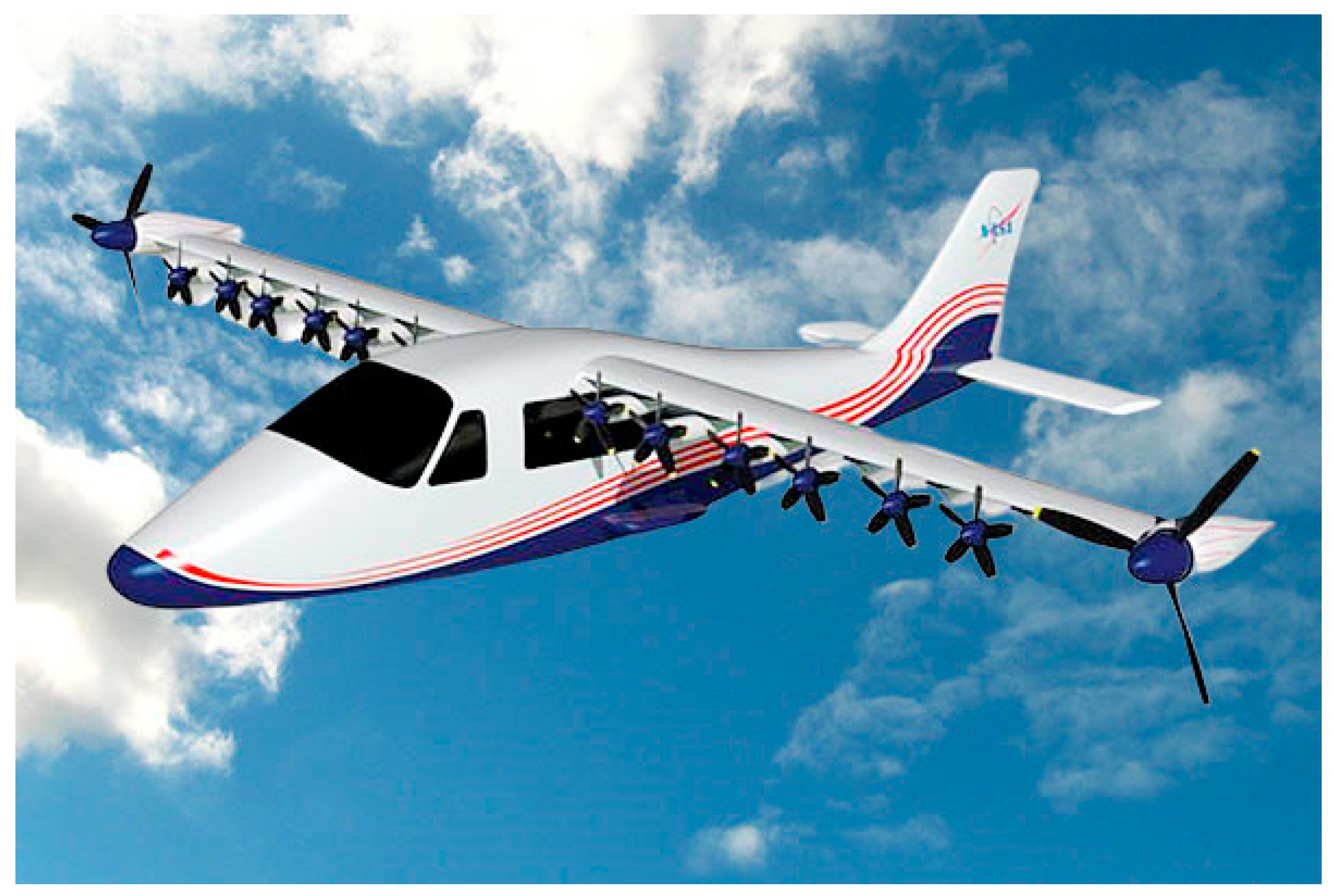
:1. Introduction
2. The Aerodynamic Interaction of the Wing and Tractor Propeller Slipstream
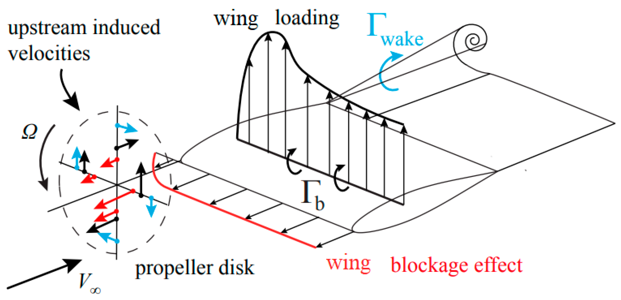
2.1. Effects of the Wing on the Propeller
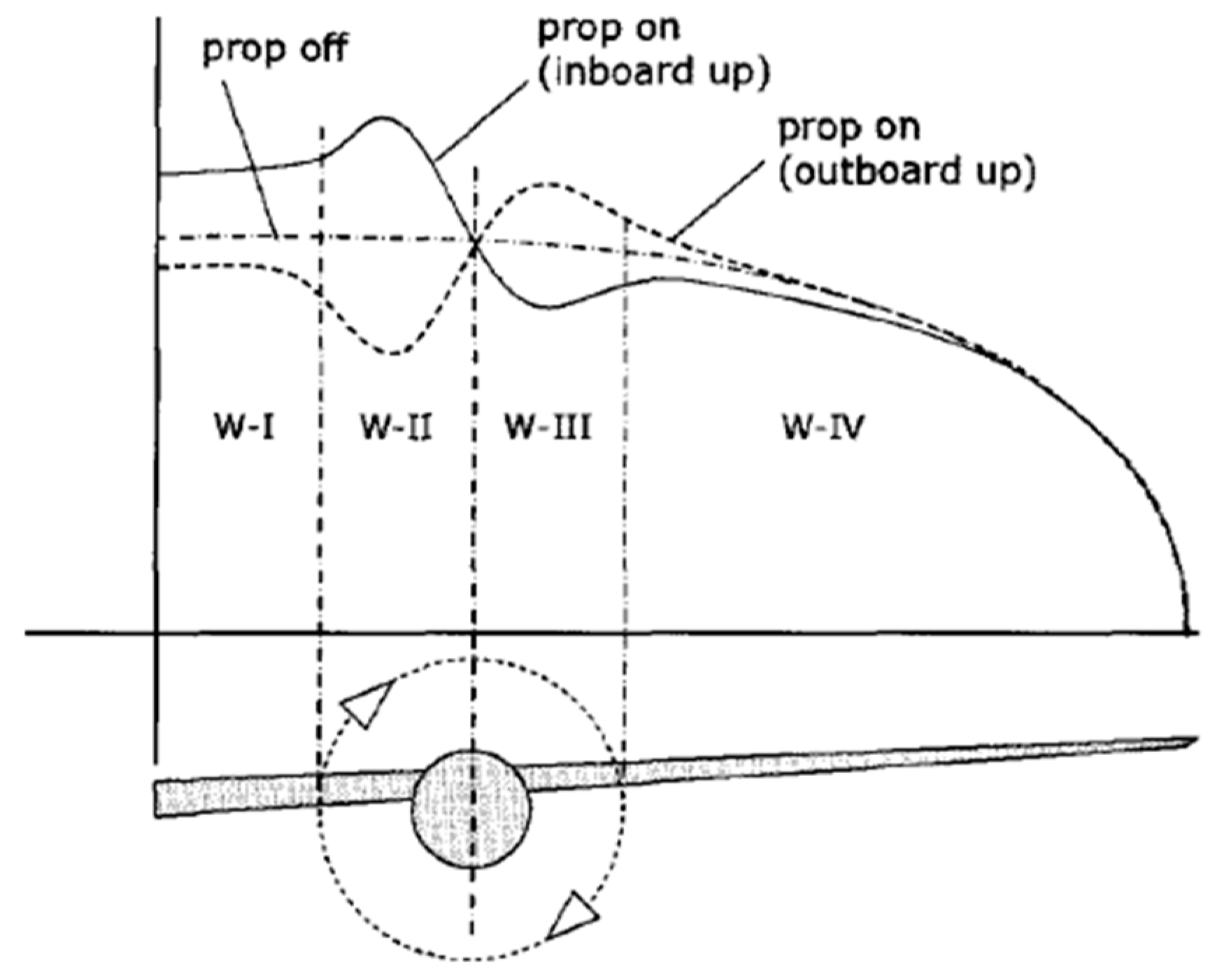
2.2. Effects of the Propeller’s Slipstream on the Wing
3. Methods
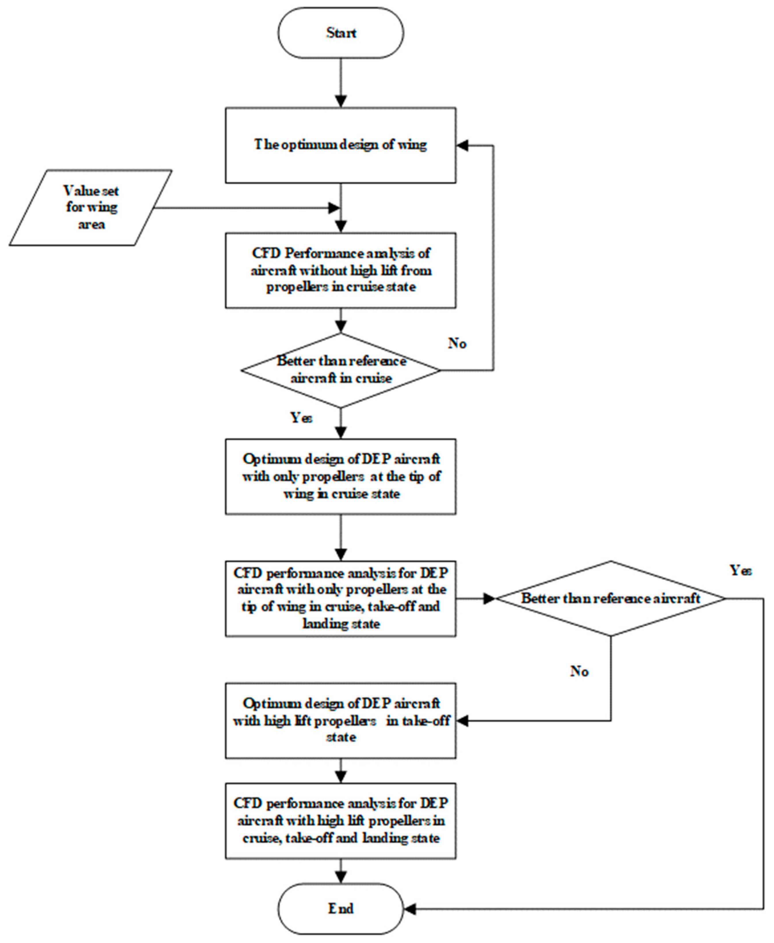
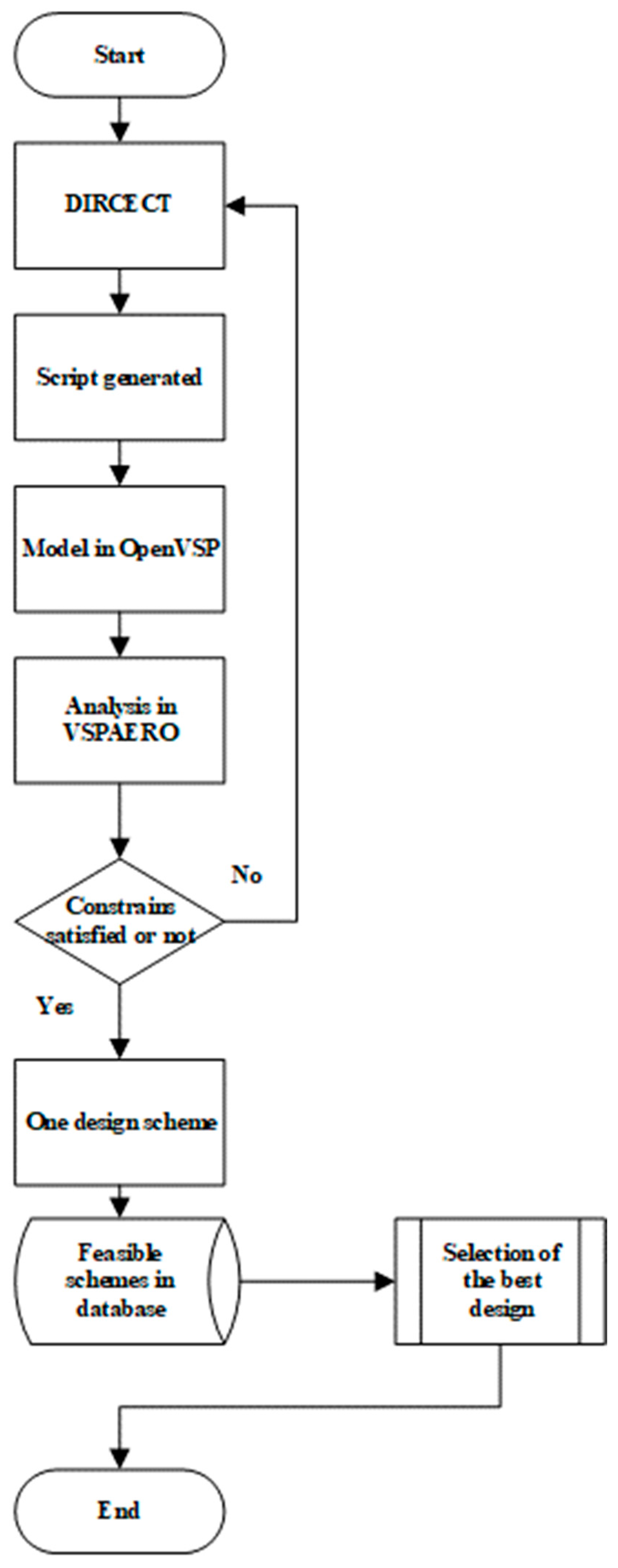
3.1. Frame for the Conceptual Design and Optimization of DEP Aircrafts
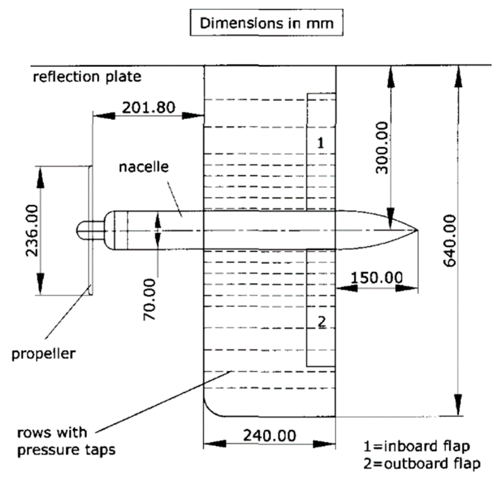
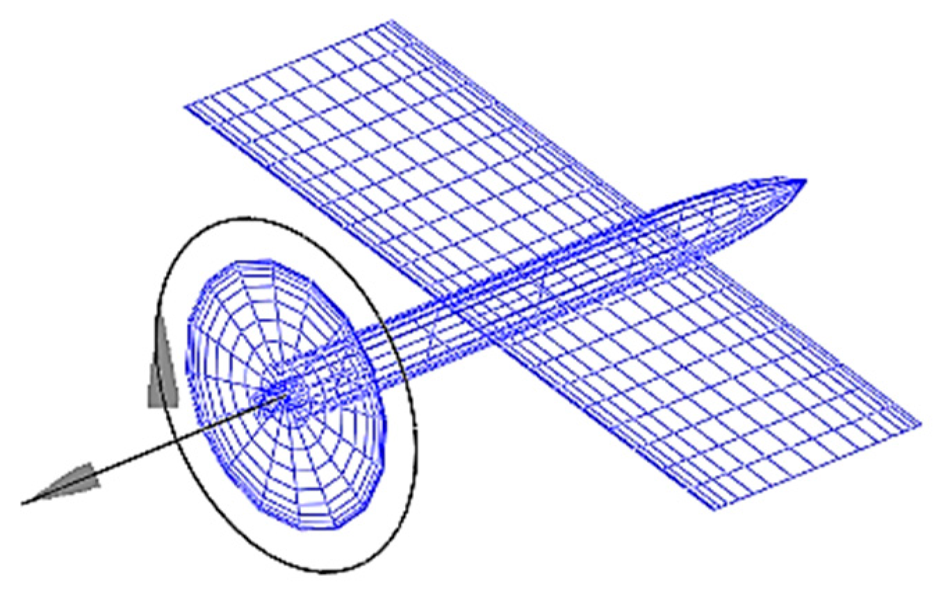
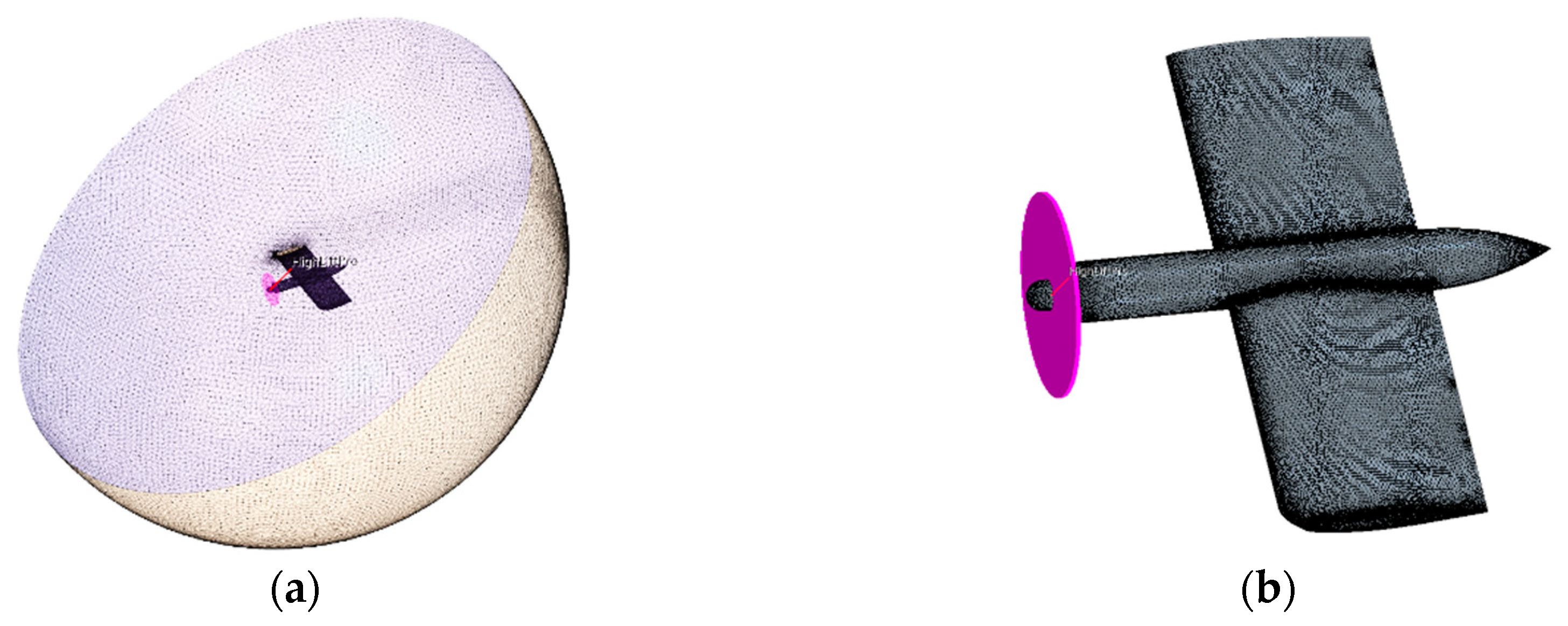
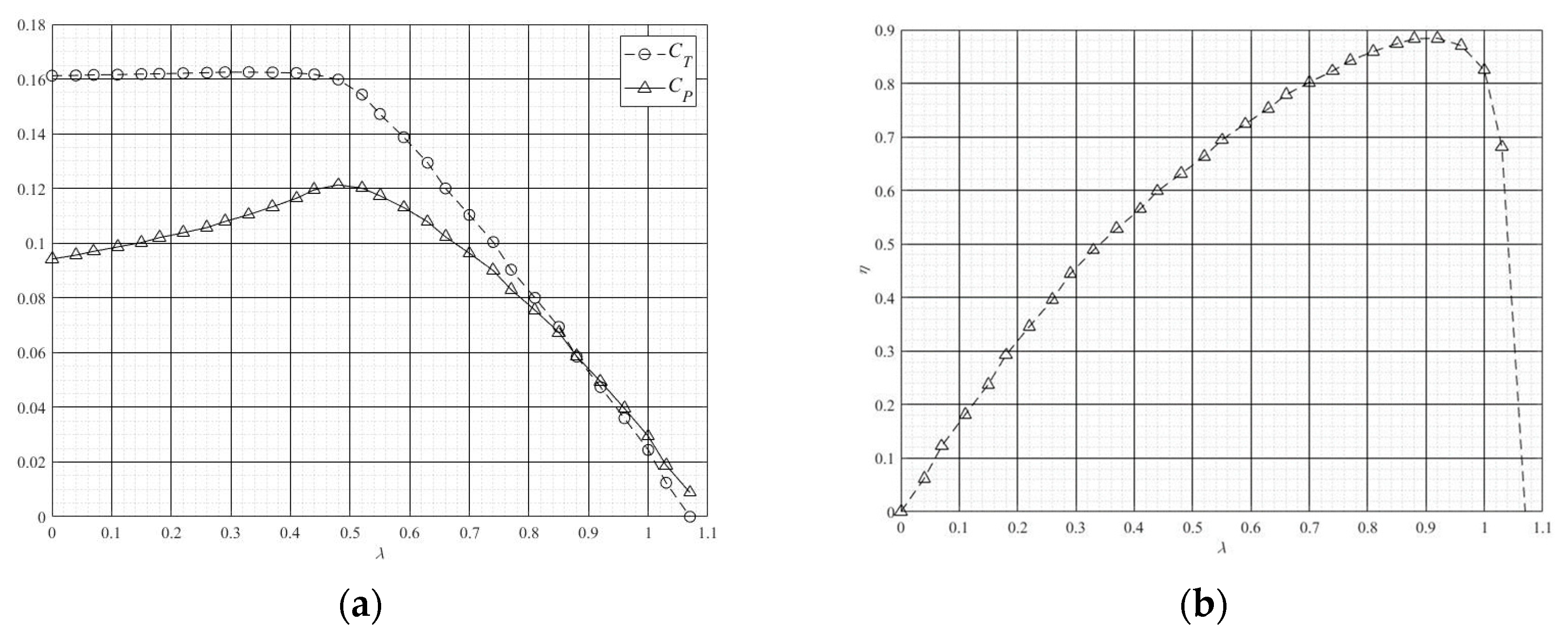
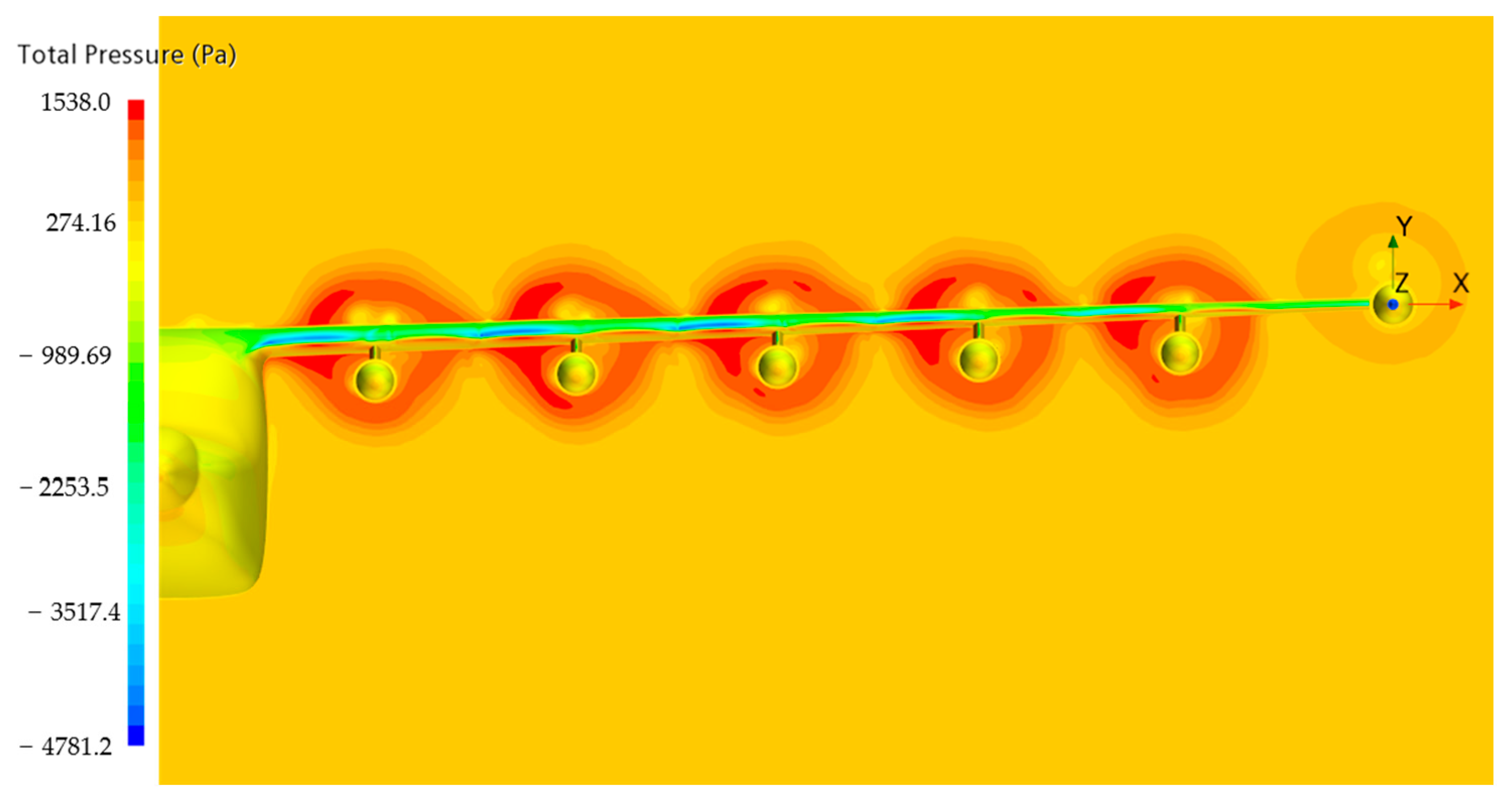
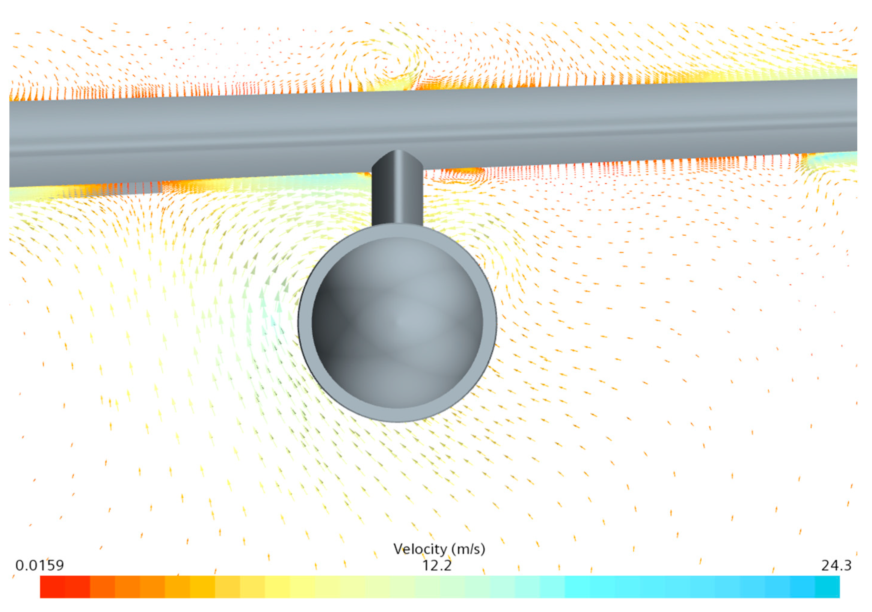
3.2. Validation of the Effectiveness of Low-Order and CFD Simulation for DEP Setup
4. Design and Optimization of DEP Aircraft
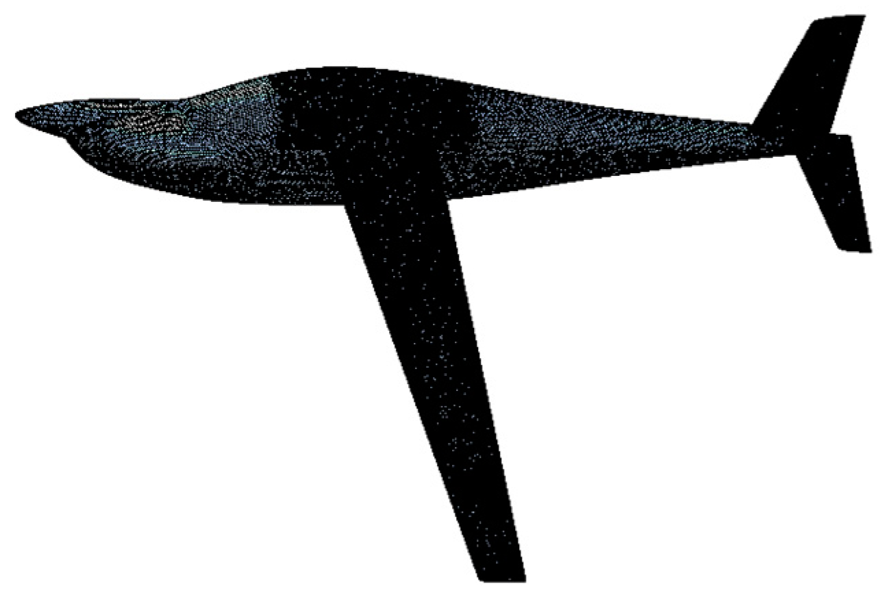
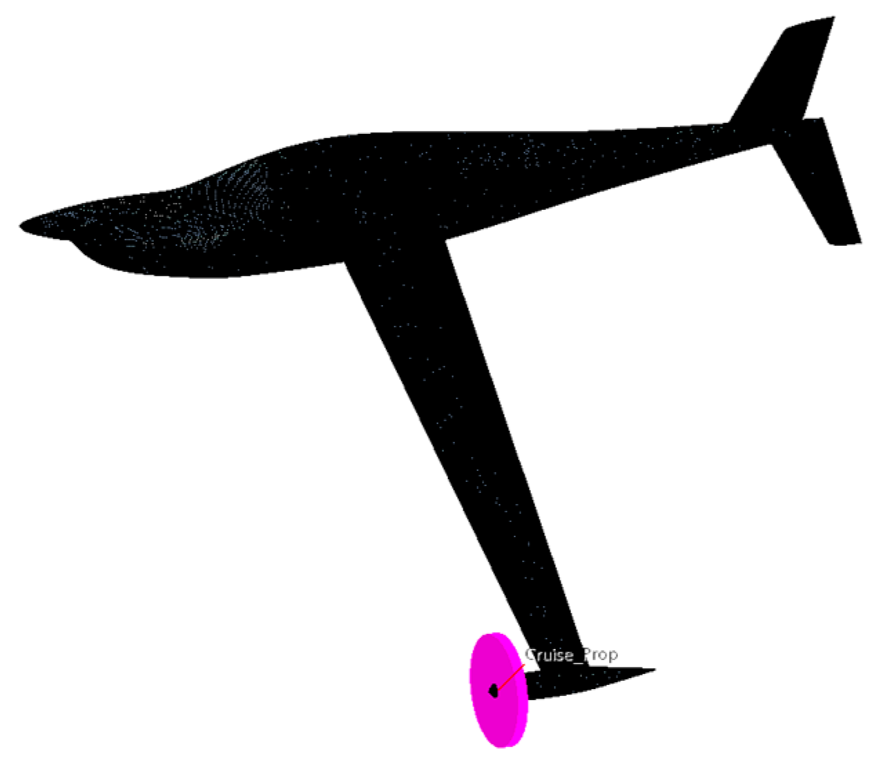
4.1. Reference Aircraft
4.2. Conceptual Design and Optimization of DEP Aircraft
4.2.1. Design and Optimization of Wing
4.2.2. Aircraft with the Optimal Wing
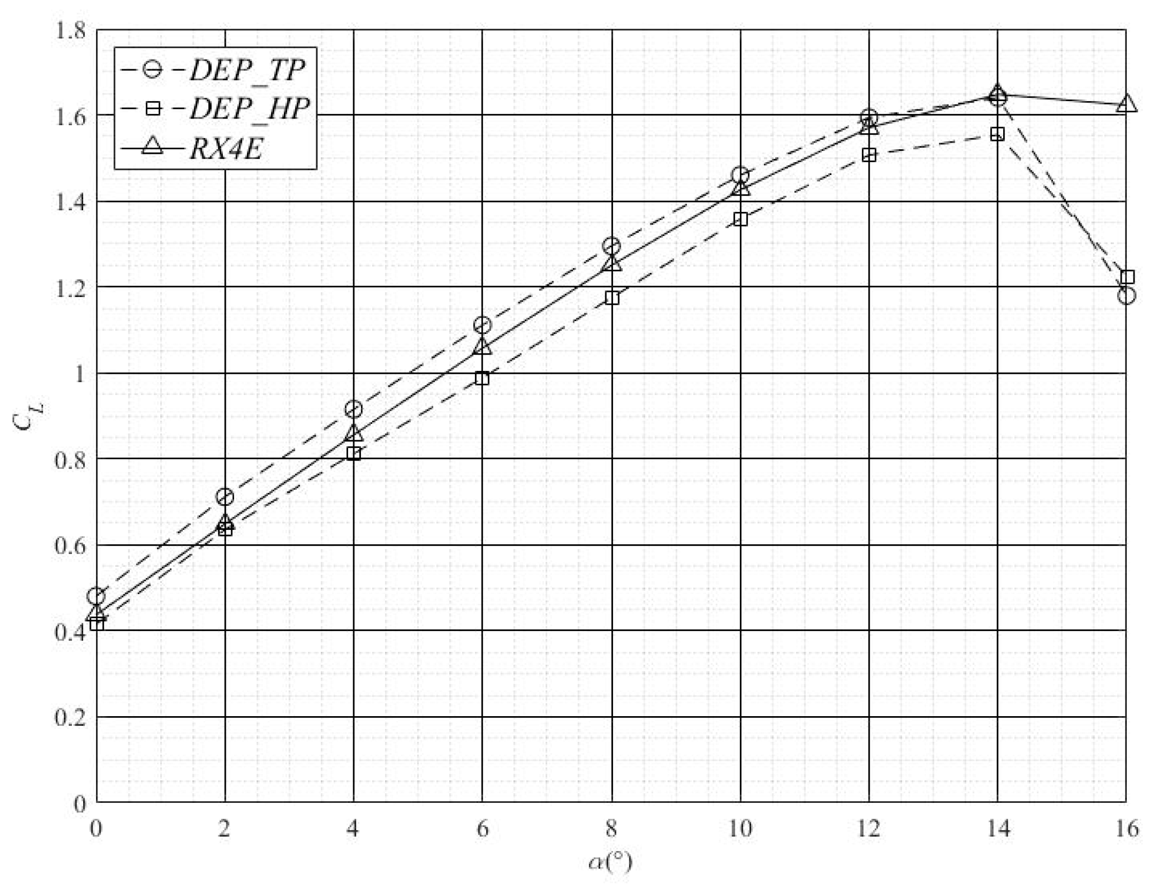
4.2.3. Design and Optimization of DEP_TP
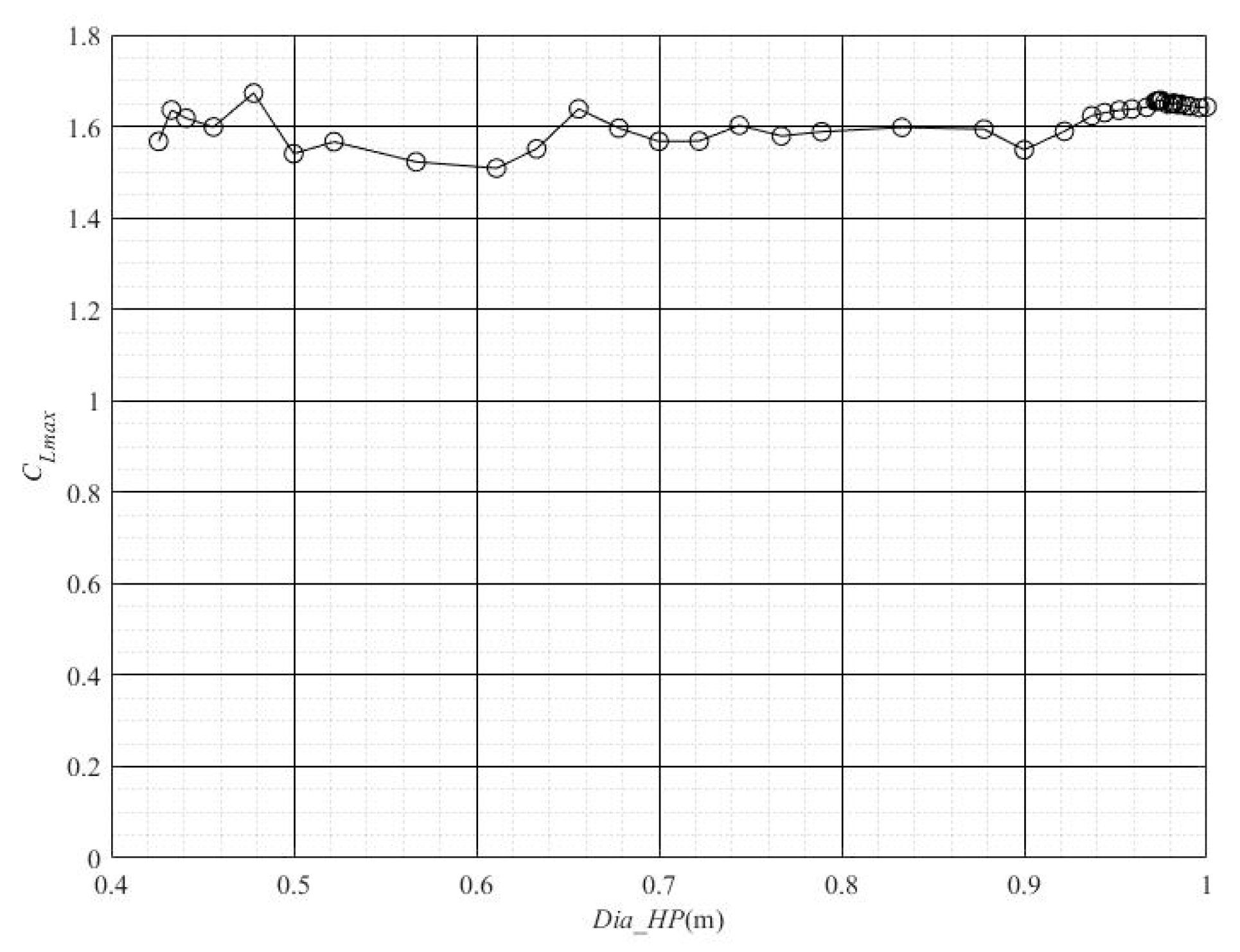
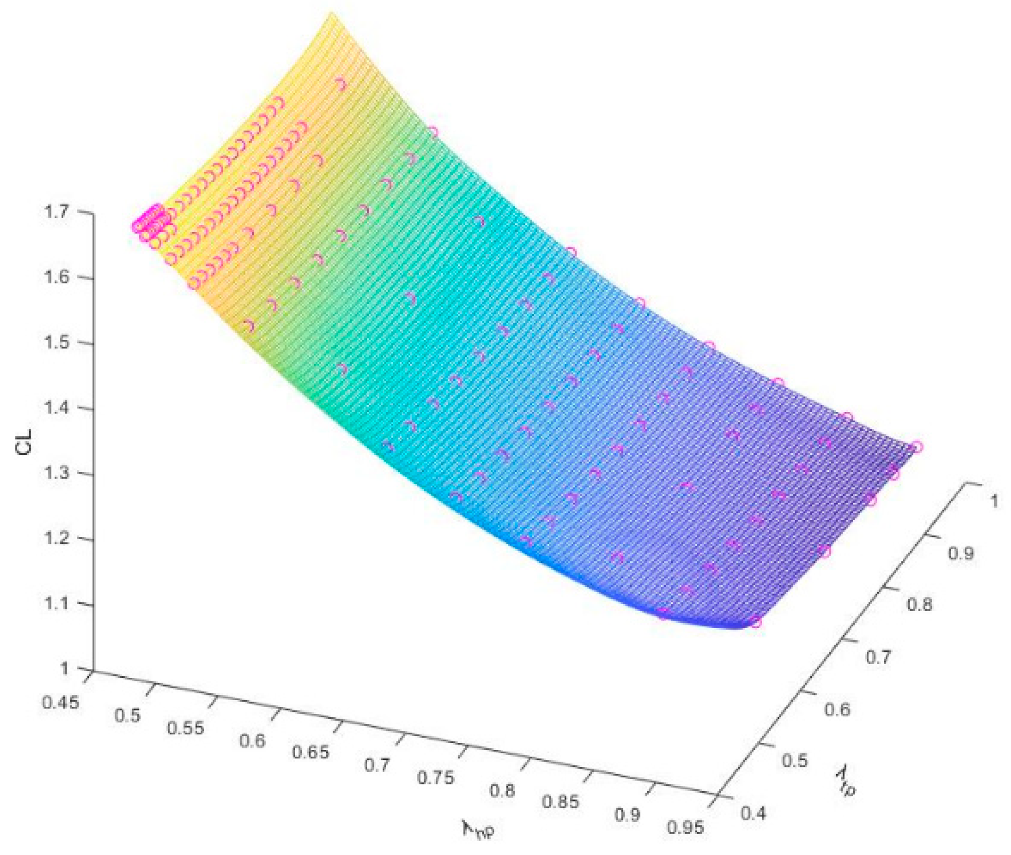
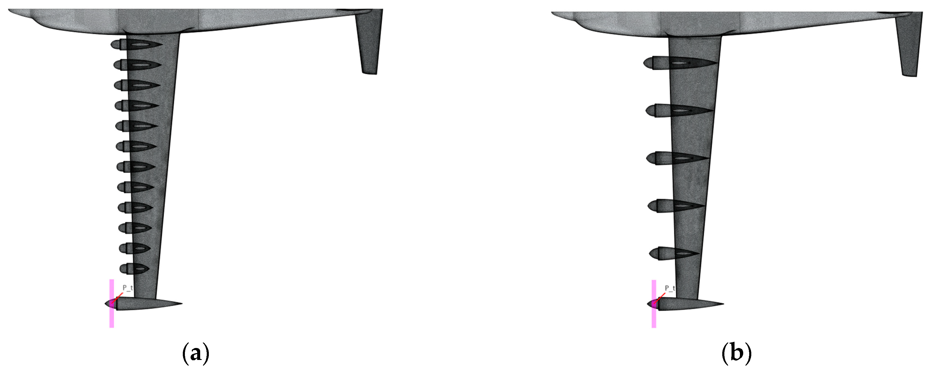
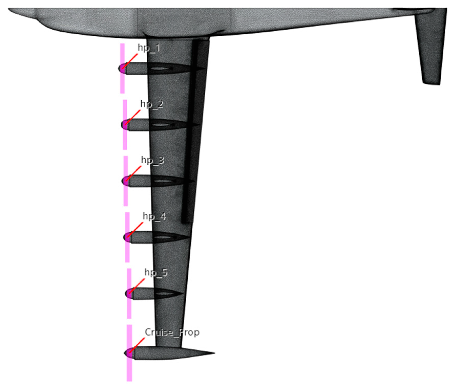
4.2.4. Design and Optimization of DEP_HP
5. Further Evaluation of DEP Aircraft
5.1. Investigation of Stall Characteristics for DEP Aircraft
5.2. Assessment of the Power Needs for DEP Aircraft
6. Conclusions and Discussion
- Under the restrictions of force balance, the increase in the cruise lift–drag ratio that results from the use of the wing-tip propellers that spin inboard and up is finite. It barely amounts to 1.7%, which is far less than the 5–10% discovered in the research of reference [8];
- Due to the use of high-lift propellers, the lift coefficient of the DEP aircraft during takeoff and landing could be satisfactorily enhanced. However, compared to conventional airplanes, DEP aircrafts would use nearly twice as much power;
- A DEP aircraft with a small wing area will have a greater stall speed than a conventional aircraft. Because the stall speed could only be attained with the propulsion systems’ power set to zero thrust or idle.
- When optimizing wings, the airfoil is ignored in favor of the wings’ planar shape. This can make it more difficult to choose the superior wing with outstanding cruising performance;
- Due to the low speed of a general aviation aircraft and the little variations in propeller size, the effects of the Reynolds number and Mach number on the performance of the propeller are disregarded in this study. The propeller performance could be overstated;
- The energy loss due to propeller thrust variability with time is neglected in the steady CFD simulation. Hence, the lift–drag ratio and propeller efficiency may be exaggerated;
- The lift–drag ratio of DEP aircrafts is sensitive to the size of the motor, and the lift–drag ratio of the DEP aircraft here is based on the popular motor size of 9-12 inches. Hence, for the alternative DEP arrangement with various size motors, the lift–drag ratio may be somewhat altered.
Author Contributions
Funding
Institutional Review Board Statement
Informed Consent Statement
Data Availability Statement
Conflicts of Interest
References
- Huang, J.; Yang, F.T. Development and challenges of electric aircraft with new energies. Chin. J. Aeronaut. 2016, 37, 57–68. [Google Scholar]
- Benjamin, J.B.; Joaquim, R.R.A.M. Electric, hybrid, and turboelectric fixed-wing aircraft: A review of concepts, models, and design approaches. Prog. Aerosp. Sci. 2019, 104, 1–19. [Google Scholar]
- Nicholas, K.B.; Craig, L.N.; Frank, P.J.; Yasky, R.; Woodham, K.; Fell, J.; Litherland, B.; Loyselle, P.; Provenza, A.; Kohlman, L.; et al. Overcoming the adoption barrier to electric flight. In Proceedings of the 54th AIAA SciTech Forum Aerospace Sciences Meeting, San Diego, CA, USA, 4–8 January 2016. [Google Scholar]
- Wang, K.; Zhou, Z.; Fan, Z.; Guo, J. Aerodynamic design of tractor propeller for high-performance distributed electric propulsion aircraft. Chin. J. Aeronaut. 2021, 34, 20–35. [Google Scholar] [CrossRef]
- Huang, J. Survey on design technology of distributed electric propulsion aircraft. Chin. J. Aeronaut. 2021, 42, 13–29. [Google Scholar]
- Kim, H.D.; Perry, A.T.; Ansell, P.J. A Review of Distributed Electric Propulsion Concepts for Air Vehicle Technology. In Proceedings of the 2018 AIAA/IEEE Electric Aircraft Technologies Symposium, Cincinnati, OH, USA, 9–11 July 2018. [Google Scholar]
- Deere, K.; Viken, J.; Viken, S.; Carter, M.B.; Wiese, M.; Farr, N. Computational Analysis of a Wing Designed for the X-57 Distributed Electric Propulsion Aircraft. In Proceedings of the 35th AIAA Applied Aerodynamics Conference AIAA AVIATION Forum, Denver, CO, USA, 5–9 June 2017. [Google Scholar]
- Borner, N.K.; Patterson, M.D.; Viken, J.K.; Moore, M.D.; Bevirt, J.; Stoll, A.M.; Gibson, A.R. Design and Performance of the NASA SCEPTOR Distributed Electric Propulsion Flight Demonstrator. In Proceedings of the 16th AIAA Aviation Technology, Integration, and Operations Conference, Washington, DC, USA, 13–17 June 2016. [Google Scholar]
- Deere, K.; Viken, S.; Carter, M.; Viken, J.K.; Cox, D.E.; Wiese, M.R.; Farr, N.L. Computational Component Build-up for the X-57 Maxwell Distributed Electric Propulsion Aircraft. In Proceedings of the 2018 AIAA Aerospace Sciences Meeting, Kissimmee, FL, USA, 8–12 January 2018. [Google Scholar]
- Veldhuis, L.L. Propeller Wing Aerodynamic Interference. Doctoral Thesis, Faculty of Aerospace Engineering, Delft University of Technology, Delft, The Netherlands, 2005. [Google Scholar]
- Sinnige, T.; van Arnhem, N.; Stokkermans, T.C.A.; Eitelberg, G.; Veldhuis, L.L.M. Wingtip-Mounted Propellers: Aerodynamic Analysis of Interaction Effects and Comparison with Conventional Layout. J. Aircr. 2019, 56, 295–312. [Google Scholar] [CrossRef]
- Stokkermans, T.C.; Arnhem, N.V.; Sinnige, T.; Veldhuis, L.L. Validation and Comparison of RANS Propeller Modeling Methods for Tip-Mounted Applications. AIAA J. 2018, 57, 1–15. [Google Scholar]
- Willemsen, R. A Sensitivity Study on the Aerodynamic Performance of a Wingtip-Mounted Tractor Propeller-Wing System. Master’s Thesis, Faculty of Aerospace Engineering, Delft University of Technology, Delft, The Netherlands, 2020. [Google Scholar]
- Stoll, A.M. Comparison of CFD and Experimental Results of the LEAPTech Distributed Electric Propulsion Blown Wing. In Proceedings of the 15th AIAA Aviation Technology, Integration, and Operations Conference, Dallas, TX, USA, 22–26 June 2015. [Google Scholar]
- Patterson, M.D.; Derlaga, G.M.; Borer, N.K. High-Lift Propeller System Configuration Selection for NASA’s SCEPTOR Distributed Electric Propulsion Flight Demonstrator. In Proceedings of the 16th AIAA Aviation Technology, Integration, and Operations Conference, Washington, DC, USA, 13–17 June 2016. [Google Scholar]
- Borner, N.K.; MOORE, M.D. Integrated Propeller-Wing Design Exploration for Distributed Propulsion Concepts. In Proceedings of the 53rd AIAA Aerospace Sciences Meeting, Kissimmee, FL, USA, 5–9 January 2015. [Google Scholar]
- Patterson, M.D.; Borer, N.K.; German, B. A Simple Method for High-Lift Propeller Conceptual Design. In Proceedings of the 54th AIAA Aerospace Sciences Meeting, San Diego, CA, USA, 4–8 January 2016. [Google Scholar]
- Rao, C.; Zhang, T.J.; Wei, C.H. Influence mechanism of propeller slipstream on wing of a distributed electric aircraft scheme. Chin. J. Aeronaut. 2021, 42, 157–167. [Google Scholar]
- Shi, J.; Zhou, J.; Wu, L.N. Aerodynamic Investigation of a General Aviation Aircraft with Distributed Electric Propulsion. In Proceedings of the 2021 IEEE International Conference on Advances in Electrical Engineering and Computer Applications (AEECA), Dalian, China, 27–28 August 2021. [Google Scholar]
- Zhang, X.Y.; Gao, Z.H.; Lei, T.; Min, Z.; Lei, W.; Zhang, X. Ground test on aerodynamic-propulsion coupling characteristics of distributed electric propulsion aircraft. Chin. J. Aeronaut. 2022, 43, 406–416. [Google Scholar]
- Cheng, Z.Y.; Yang, Y.X.; Zhang, X.C.; Yu, L.F.; Ye, B. Rapid evaluation and method for aerodynamic characteristics of distributed electric propulsion aircraft concept scheme. J. Beijing Univ. Aeronaut. Astronaut. 2021, OL, 1–16. [Google Scholar]
- Yang, W.; Fan, Z.L.; Wu, W.H.; Lei, Y.U. Optimal design of distributed propeller layout considering slipstream effect. Acta Aerodyn. Sin. 2021, 39, 71–79. [Google Scholar]
- Pela, P.; Leise, P.; Meck, M. Sustainable aircraft design—A review on optimization methods for electric propulsion with derived optimal number of propulsors. Prog. Aerosp. Sci. 2021, 123, 10074. [Google Scholar]
- Erhard, R.M.; Clarke, M.A.; Alonso, J.J. A Low-Cost Aero-Propulsive Analysis of Distributed Electric Propulsion Aircraft. In Proceedings of the AIAA Scitech 2021 Forum, Virtual Event, 11–15 & 19–21 January 2021. [Google Scholar]
- Lei, Y.; Yang, W.Q.; Huang, Y.Y. Aerodynamic performance of distributed electric propulsion with wing interaction. J. Zhejiang Univ. Sci. A 2022, 23, 27–39. [Google Scholar] [CrossRef]
- Olichevis Halila, G.L.; Neves Pedreiro, L.; Silveira Molina, E.; Savio, M.C. Efficient Aerodynamic Analysis for Propeller Aircraft Including Viscous Effects. In Proceedings of the AIAA SCITECH 2022 Forum, Virtual, San Diego, CA, USA, 3–7 January 2022. [Google Scholar]
- D’angelo, B.K. Low-Order Modeling of Propeller-Wing Interaction Using a Modified Weissinger Method. Master’s Thesis, North Carolina State University Aerospace Engineering, Raleigh, NC, USA, 2021. [Google Scholar]
- Alba, C.; Elham, A.; German, B.; Veldhuis, L.L. A Surrogate-Based Multi-Disciplinary Design Optimization Framework Exploiting Wing-Propeller Interaction. In Proceedings of the 18th AIAA/ ISSMO Multidisciplinary Analysis and Optimization Conference, Denver, CO, USA, 5–9 June 2017. [Google Scholar]
- Xue, C.; Zhou, Z.; Fan, Z.Y.; Li, X. Design of target propeller slipstream under propeller-wing interaction. J. Aerosp. Power 2021, 36, 104–118. [Google Scholar]
- Alvarez, E.J.; Ning, A. Development of a Vortex Particle Code for the Modeling of Wake Interaction in Distributed Propulsion. In Proceedings of the 2018 Applied Aerodynamics Conference, Atlanta, GA, USA, 25–29 June 2018. [Google Scholar]
- Alvarez, E.J.; Ning, A. Modeling Multirotor Aerodynamic Interactions through the Vortex Particle Method. In Proceedings of the AIAA Aviation 2019 Forum, Dallas, TX, USA, 17–21 June 2019. [Google Scholar]
- Alvarez, E.J.; Ning, A. High-fidelity Modeling of Multirotor Aerodynamic Interactions for Aircraft Design. AIAA J. 2020, 58, 4385–4400. [Google Scholar] [CrossRef]
- Arnhem, N.V.; Sinnige, T.; Stokkermans, T.C.; Eitelberg, G.; Veldhuis, L.L. Aerodynamic Interaction Effects of Tip-Mounted Propellers Installed on the Horizontal Tailplane. In Proceedings of the 2018 AIAA Aerospace Sciences Meeting, Kissimmee, FL, USA, 8–12 January 2018. [Google Scholar]
- Wu, J.; Tong, S.X.; Gao, F.; Yin, C.; Yang, F.T. Comparison of Aerodynamic Layout Schemes of a Fuel Cell Aircraft. Sci. Technol. Eng. 2021, 21, 13574–13579. [Google Scholar]
- Gablonsky, J.M.; Kelley, C.T. A Locally-Biased form of the DIRECT Algorithm. J. Glob. Optim. 2001, 21, 27–37. [Google Scholar] [CrossRef]
- Bohari, B.; Bronz, M.; Benard, E.; Borlon, Q. Conceptual Design of Distributed Propeller Aircraft: Linear Aerodynamic Model Verification of Propeller-Wing Interaction. In Proceedings of the 7th European Conference for Aeronautics and Aerospace Sciences (EUCASS), Milan, Italy, 3–6 July 2017. [Google Scholar]
- Stone, R.H. Aerodynamic Modeling of the Wing-Propeller Interaction for a Tail-Sitter Unmanned Air Vehicle. J. Aircraft. 2008, 45, 198–210. [Google Scholar] [CrossRef]
- Ma, Y.; Zhang, W.; Zhang, Y.; Zhang, X.; Zhong, Y. Sizing Method and Sensitivity Analysis for Distributed Electric Propulsion Aircraft. J. Aircr. 2020, 57, 730–741. [Google Scholar] [CrossRef]
- Bright, A.A.; Clara, G. Electric aviation: A review of concepts and enabling technologies. Transp. Eng. 2022, 9, 100134. [Google Scholar]


| α (°) | Method | CL | CD |
|---|---|---|---|
| 0 | Test | 0.0055 | −0.0986 |
| VSPAERO | −0.0028 | −0.0998 | |
| 4 | Test | 0.3135 | −0.0916 |
| VSPAERO | 0.3026 | −0.0873 |
| α (°) | Method | CL | CD |
|---|---|---|---|
| 0 | Test | 0.0055 | −0.0986 |
| CFD | −0.0070 | −0.0948 | |
| 4 | Test | 0.3135 | −0.0916 |
| CFD | 0.3096 | −0.0862 |
| Variables | Minimum | Maximum |
|---|---|---|
| Wing root chord (m) | 1.20 | 1.50 |
| Wing tip chord (m) | 0.45 | 0.60 |
| Half of wing span (m) | 5.50 | 7.00 |
| Wing geometric twist angle (°) | −3.00 | 0.00 |
| Wing incidence angle (°) | 0.00 | 3.00 |
| Wing dihedral angle (°) | 0.00 | 2.50 |
| Variables | Optimal Solution |
|---|---|
| Wing root chord (m) | 1.21 |
| Wing tip chord (m) | 0.45 |
| Half of wing span (m) | 6.33 |
| Wing geometric twist angle (°) | −1.75 |
| Wing incidence angle (°) | 2.60 |
| Wing dihedral angle (°) | 2.10 |
| Variables | Minimum | Maximum |
|---|---|---|
| Diameter of propeller (m) | 0.70 | 1.50 |
| Advance ratio of propeller | 0.63 | 0.96 |
| Variables | Optimal Solution |
|---|---|
| Diameter of propeller (m) | 1.067 |
| Advance of propeller | 0.895 |
| Variables | Minimum | Maximum |
|---|---|---|
| Diameter of high-lift propeller (m) | 0.40 | 1.00 |
| Advance of high-lift propeller | 0.46 | 0.96 |
| Advance of wing-tip propeller | 0.46 | 0.96 |
Disclaimer/Publisher’s Note: The statements, opinions and data contained in all publications are solely those of the individual author(s) and contributor(s) and not of MDPI and/or the editor(s). MDPI and/or the editor(s) disclaim responsibility for any injury to people or property resulting from any ideas, methods, instructions or products referred to in the content. |
© 2023 by the authors. Licensee MDPI, Basel, Switzerland. This article is an open access article distributed under the terms and conditions of the Creative Commons Attribution (CC BY) license (https://creativecommons.org/licenses/by/4.0/).
Share and Cite
Wu, J.; Gao, F.; Li, S.; Yang, F. Conceptual Design and Optimization of Distributed Electric Propulsion General Aviation Aircraft. Aerospace 2023, 10, 387. https://doi.org/10.3390/aerospace10050387
Wu J, Gao F, Li S, Yang F. Conceptual Design and Optimization of Distributed Electric Propulsion General Aviation Aircraft. Aerospace. 2023; 10(5):387. https://doi.org/10.3390/aerospace10050387
Chicago/Turabian StyleWu, Jiang, Feng Gao, Shengwen Li, and Fengtian Yang. 2023. "Conceptual Design and Optimization of Distributed Electric Propulsion General Aviation Aircraft" Aerospace 10, no. 5: 387. https://doi.org/10.3390/aerospace10050387