1. Introduction
Airbreathing hypersonic aircraft, powered by a combined-cycle engine such as a turbojet-based combined-cycle (TBCC) or a rocket-based combined-cycle (RBCC) engine, are expected to operate at an altitude of airspace above 20 km and at speeds above Mach 5, and also have the capability for horizontal takeoff and horizontal landing like conventional aircraft. Compared to conventional aircraft, this type of novel aircraft with a higher and faster flight envelope has great potential value in both commercial and military operations.
For civilian transportation, hypersonic transport systems have the potential to greatly reduce travel time for critical trips, which would be particularly valuable for intercontinental transportation and medical rescue operations. The European project LAPCAT-2 (Long-Term Advanced Propulsion Concepts and Technologies) had the ambitious goal to devise hypersonic transport that would be able to travel from Brussels to Sydney in 2 to 4 h [
1]. Several design concepts of hypersonic transport systems that are powered by a combined cycle engine with cruise speeds of Mach 5 and Mach 8 were studied [
2,
3,
4]. The key technology issues, such as engine–airframe integration tools and methodology, high-speed airbreathing cycle analysis, and the experiments to evaluate the design, were addressed by the LAPCAT-II Project [
5]. The free-fly test of a vehicle model with an integrated airbreathing propulsion unit in a wind tunnel was conducted at Mach 8 successfully. More recently, H2020 STRATOFLY project, funded by the European Commission under the Horizon 2020 framework, is devoted to studying the feasibility of high-speed civil transportation at stratospheric altitudes, with the goal of reducing travelling time by one order of magnitude compared to current civil transport. It aims to assess the potential of this type of transport to reach technology readiness level (TRL) 6 by 2035 [
6]. The main issues of the STRATOFLY project are related to thermal and structural integrity, low emissions combined cycle engines, subsystems design and integration, environmental impact, noise emissions, social acceptance, and economic viability. Some investigations indicated that the use of unexploited flight routes in the stratosphere might offer a solution to the current congested flight paths, while ensuring a minimal environmental impact in terms of emitted noise and greenhouse gasses [
7]. The design concept of the STRATOFLY MR3 vehicle, fueled with liquid hydrogen, promises to limit the overall environmental impact. A cost estimation model for liquid hydrogen was developed [
8], which can be used to estimate the direct operating costs (DOC) of hypersonic transport. The share of fuel cost on the DOC can be reduced from 90% to 70% in a future scenario (2050). In the realm of military operations, the rapid response capabilities of hypersonic aircraft provide significant advantages for IRS (intelligence, reconnaissance, and surveillance) missions [
9]. Lockheed-Martin has introduced the SR-72, a hypersonic reconnaissance aircraft design concept. A more comprehensive review of the technical issues and challenges associated with the design of hypersonic aircraft is presented in reference [
10].
Aircraft design is a process of progressive refinement, and usually consists of three phases: conceptual design, preliminary design, and detail design [
11]. Conceptual design is the early phase in aircraft design. An essential task of this phase is initial sizing of an aircraft, in which the aircraft’s primary parameters (such as wing size, takeoff gross weight, and required thrust) should be reasonably estimated according to top-level design requirements. The following preliminary design will be carried out with this conceptual design. An unreasonable initial sizing will result in more design iterations and rework. Therefore, the rationality of the initial sizing is essential in aircraft conceptual design [
12].
Currently, the initial sizing method for conventional aircraft design is mature. Different from conventional aircraft, airbreathing hypersonic aircraft are usually powered by a combined cycle engine (TBCC engine or RBCC engine). Another issue is that hypersonic aircraft usually require much larger fuel volumes, which has a critical impact on the initial sizing. Furthermore, hypersonic aircraft may use hydrocarbon fuel or liquid hydrogen fuel [
13]. Compared with hydrocarbon fuel, liquid hydrogen fuel has a higher mass energy density, but a lower volumetric energy density [
14,
15]. This means that fuel type also has a substantial impact on the initial sizing. However, conventional initial sizing methods do not deal with those issues and are not suitable for airbreathing hypersonic aircraft. Therefore, there is a need to study new methods of initial sizing for airbreathing hypersonic aircraft.
Czysz [
16] studied the initial sizing for hypersonic aircraft and proposed an approach reflecting the relationship between the size and weight by using the Küchemann parameter, which indicates the slenderness of the aircraft’s overall configuration in terms of the aircraft volume and surface area. Ingenito et al. [
17,
18] applied Czysz’s approach to the initial estimations of weight and size for hypersonic commercial airliners, and also analyzed the effect of the Küchemann slenderness parameter on the aircraft weight and volume. Both Coleman [
19] and Haley et al. [
20] studied the initial sizing of hypersonic transport aircraft and hypersonic endurance demonstrator by use of weight and volume equations, and the constraint analysis for thrust-to-weight ratio and wing loading. Ferretto et al. [
21] updated the semi-empirical models in classical theories to cover high speeds and validated the methods with a high-speed vehicle case study. Andro et al. [
22] developed a tool for the initial sizing of high-speed civil transportation aircrafts and added cost models to assess ticket prices.
However, the characteristics of engines are represented simply by the engine thrust-to-weight ratio or specific impulse in the above studies, which results in some shortcomings. Those studies only considered the impact of thrust or specific impulse on the engine’s weight but did not consider the impact of thrust on engine volume. In fact, the volume of the engine also changes with the thrust or specific impulse. The change of engine volume with the thrust might have non-ignorable impact on the initial sizing results. The accuracy of initial sizing methods is reduced without consideration of the engine volume change. In addition, the combined cycle engine works in different modes during the flight with different speeds and altitudes. The engine performance of each mode is different. However, the above studies did not deal with the performance difference of the engine modes. The impacts of the thrust trade among the engine modes on the aircraft takeoff gross weight have not been studied. However, the thrust trades of the engine modes have considerable impacts on the aircraft takeoff gross weight.
This paper presents an improved initial sizing method for hypersonic aircraft conceptual design based on the existing methods. In this improved method, empirical models of the combined cycle engines are incorporated into initial sizing procedures. By using those engine models, the volume for different engine modes is related to its thrust, and engine performance in the different modes is estimated. The advantage of this improvement is that the impact of the engine volume change on initial sizing results are counted, and the thrust trades of the engine modes can be conducted to find the minimum takeoff gross weight of the aircraft.
We will use an illustrative hypersonic aircraft to present the process and results of the method. The paper is arranged in the following way:
Section 2 introduces design requirements and configuration of the illustrative hypersonic aircraft. The information in
Section 2 serves as the starting point for the initial sizing.
Section 3 details the procedure of the initial sizing method for the illustrative hypersonic aircraft. In
Section 4, the initial sizing results of the illustrative hypersonic aircraft are presented and discussed. In
Section 5, sensitivity analysis is conducted to indicate the impact of technology parameters on the initial sizing. The paper ends with a summary in
Section 6.
2. Design Requirements and Configuration
The initial sizing starts from the design requirements and overall configuration of the aircraft. In this section, the top-level design requirements and configuration of an illustrative airbreathing hypersonic aircraft are introduced.
2.1. Design Requirements and Mission Profile
The illustrative aircraft is considered an experimental aircraft that is intended to test and verify technical issues, such as performance of the combined cycle engine, aerodynamics, structure, and others. The illustrative aircraft should be able to perform horizontal takeoff and land at conventional airports. In consideration of the costs, the takeoff gross weight of the illustrative aircraft should be less than 15,000 kg. For the purpose of the technology verification, the illustrative aircraft should have a cruise time no less than 10 min at Mach 8. According to the above considerations, the major top-level design requirements of the illustrative aircraft are listed as follows:
- (1)
payload weight is 10,000 kg;
- (2)
cruise altitude is 30 km;
- (3)
cruise Mach number is 8;
- (4)
cruise range is 2000 km;
- (5)
takeoff and landing distances should be less than 2500 m.
An assumed mission profile is illustrated in
Figure 1. The entire mission profile includes eight mission segments:
- (1)
takeoff;
- (2)
acceleration to Ma = 0.7 at constant altitude;
- (3)
acceleration to Ma = 0.9 and climb to 10 km;
- (4)
acceleration to Ma = 1.7 at constant altitude;
- (5)
climb to 30 km with constant dynamic pressure;
- (6)
cruise at Ma = 8 and altitude 30 km;
- (7)
unpowered decent at maximum L/D;
- (8)
landing.
2.2. Propulsion System and Aircraft Configuration
According to the above performance requirements and mission profile, the illustrative aircraft should have the ability to accelerate from subsonic to hypersonic and fly from low altitude to high altitude. Conventional engines like the turbojet are obviously unable to complete this mission.
Extensive research on airbreathing propulsion systems for hypersonic aircraft have been conducted since the 1960s [
23]. Several combined cycle engine concepts, such as the RBCC (rocket based combined cycle) engine and the TBCC (turbojet based combined cycle) engine, show great potential [
24]. The RBCC engine combines a ducted rocket, a ramjet, and a scramjet, where the three parts share one flow path. The TBCC engine is a turbine engine combined with a ramjet and a scramjet. The TBCC engine is further divided into two classes, where the turbine engine shares a flow path with the ramjet and scramjet. The RBCC engine could be lighter than the TBCC engine, but the TBCC engine could generate higher specific impulse [
25].
In this study, the TBCC engine is selected as propulsion system, as shown in
Figure 2. The TBCC engine merges a modified turbojet with a dual-mode ramjet. The propulsion system can work in three different modes: turbojet, ramjet, and scramjet. The turbojet mode is assumed to operate up to
Ma = 3; above
Ma = 3, the ramjet mode starts to work and operates up to
Ma = 6; above
Ma = 6, the scramjet mode operates. The fuel of the propulsion system is liquid hydrogen.
To balance the aerodynamic performance between low speeds and high speeds, and to accommodate the fuel and the payload, a blended wing body configuration with a low aspect ratio wing is selected for the illustrative aircraft. As shown in
Figure 3, the engine is mounted under the blended wing body and the surface of fuselage in front of the engine is almost flat, which makes the air intake more uniform and stable. A vertical tail is located on the rear of the fuselage to ensure lateral-directional stability and control.
3. Method of Initial Sizing
The task of the initial sizing is to estimate the aircraft takeoff gross weight, empty weight, fuel weight, planform area, volume, and required thrust of the TBCC engine (three modes). The initial sizing method consists of weight and volume estimations, the constraint analysis for the thrust-to-weight ratio, and the wing loading. Additionally, the engine characteristics and aerodynamic characteristics should be reasonably estimated by approximate models. Those engine data and aerodynamic data are the input for the weight and volume estimation, as well as the constraint analysis. SI units are used in the following formulas.
3.1. Methods of Weight and Volume Estimation
3.1.1. Weight Estimation
The takeoff gross weight (TOGW),
Wto is simply the sum of empty weight (
We), payload weight (
Wp), and fuel weight (
Wf).
The payload is specified in the design requirements. The empty weight and fuel weight estimations are mainly concerned with the following.
For conventional aircraft, there exist various empty weight fraction equations derived from historical data of existing aircraft [
11,
26]. However, for the airbreathing hypersonic aircraft, we do not have such empty weight fraction equations due to a lack of historical data. To deal with this problem, a buildup method for empty weight estimation is used in this study. The empty weight is divided into six individual components, including body structure, thermal protection system, landing gear, propulsion system, tank, and subsystem. The weight for each component is estimated using statistical equations or empirical formulas.
The body structural weight (
Sstr) is estimated by the wetted area of the aircraft and the structural weight index.
where
Swet is the wetted area of the whole aircraft.
Istr is the structural weight index [
16], which is defined as the ratio of the weight of the structure to the wetted area.
Istr depends on materials, structural concept, and manufacturing capability. The values of
Istr can be estimated on historic data and an educated guess, and its typical value is listed in
Table 1 at end of
Section 3.1.
Splan is the planform area.
Kw is the ratio of wetted area to planform area, which depends on the specific aircraft configuration [
16].
The weight of thermal protection system (
Wtps) is simply estimated by the wetted area and the thermal protection structural index.
where
Itps is the thermal protection structural index that reflects the materials, structure, and manufacturing capability of thermal protection system.
The landing gear weight (
Wlg) is estimated by the following statistical equation [
15]:
The propulsion system weight (
Wprop) is related to its thrust. Details will be described in
Section 3.4.1.
The fuel tank weight (
Wtankstr) is estimated by its volume and structural weight index:
where
KIT is 1 if the fuel tank is integrated with body structure, and
KIT is 0 if the tank is isolated from body structure.
Itank is the tank weight index that depends on tank materials, structural concept, and manufacturing capability. The tank volume (
Vtank) is calculated from the fuel weights (
Wf) and its densities. If there are two different kinds of fuel used, the tank volume should be calculated as the following:
where
r1 and
r2 are the mass ratio of two kinds of fuel;
ρ1 and
ρ2 are the densities of two kinds of fuel; and
kpf is the fuel packing factor that reflects the ratio between the volume of fuel and tank.
The subsystem weight (
Wsub) is estimated by statistical equations.
where
Isub is the ratio of subsystem weight to takeoff gross weight.
The fuel weight is estimated by mission analysis. The weight fraction of each mission segment needs to be estimated in mission analysis. The mission segment weight fraction is defined as the ratio of the weight at the end of a mission segment to the weight at the beginning. For any mission segment “
i”, the mission segment weight fraction can be expressed as (
). In the segments of warmup, takeoff, and landing, the propulsion system works in turbojet mode and the aircraft speed is low, which is similar to the conventional aircraft. Thus, the weight fractions for the segments of warmup, takeoff, and landing can be estimated based on historical data [
11]. The descent segment is assumed to be unpowered, hence its weight fraction is 1. The weight fractions for other mission segments including climb and acceleration and cruise, are calculated from Equation (8), which is derived from force equation [
27].
where
h = altitude;
V = velocity;
g = acceleration of gravity;
Isp = specific impulse;
D = drag;
T = thrust; and Δ
t = flight time.
Then, the total fuel weight fraction can be expressed as follows:
where
krf represents the proportion of reserve fuel and trapped fuel in the total fuel, assumed to be 6% [
11].
If the expendable payload (
Wpe) is dropped at the end of some mission segment “
j”, the Equation (9) should be revised into Equation (10).
The takeoff gross weight (
Wto) can be estimated by the sum of all of the above weights and is represented by the following:
3.1.2. Volume Estimation
For hypersonic aircraft, a large portion of the takeoff gross weight is fuel weight, which demands large volume, especially when hydrogen fuel is used. Therefore, the aircraft volume should be estimated in the initial sizing for airbreathing hypersonic vehicles.
Similar to weight estimation, the total volume of the aircraft (
Vtot) is divided into nine parts, including body structure, thermal protection system, landing gear, propulsion system, tank structure, tank capacity, payload, and void. The volumes of body structure, thermal protection system, and tank structure can be estimated by their weights and density of materials. The volume of the propulsion system depends on the thrust. Details will be represented in
Section 3.4.1. The volumes of the landing gear, subsystem, and void are estimated empirically [
19].
The total volume of the aircraft (
Vtot) can be estimated by the sum of the volume of each part and represented by the following:
where
Klg is the landing gear volume coefficient;
Vprop is the propulsion system volume;
ρtankstr is the density of tank structure;
Ksub is the subsystem volume coefficient; and
Kvoid is the void volume coefficient.
3.1.3. Solution for Weight and Volume Equations
As indicated in the fuel weight estimation Equation (10), the fuel weight (
Wf) is a function of the takeoff gross weight (
Wto). The
Wto can be found by the weight estimation Equation (11) if the planform area (
Splan) and engine weight (
Wprop) are determined. Using the volume estimation Equation (12), the total volume (
Vtot) will be found if
Splan,
Wto, and the engine volume (
Vprop) are determined. The
Wprop and
Vprop can be estimated for a given thrust in
Section 3.4.1. There are three unknowns (
Wto,
Splan, and
Vtot) in Equations (11) and (12), where
Splan appears in the both equations. An additional equation is needed to find the three unknowns.
Küchemann introduced the coefficient (
τ) that is used to link the aircraft volume and its planform area [
28].
The coefficient
τ is also referred to as the Küchemann slenderness parameter and can be estimated given a specific configuration [
16].
Now, using Equations (11) and (12) with Equation (13) simultaneously, the three unknowns (Wto, Splan, and Vtot) can be solved for the given engine thrust. Once Wto, Splan, and Vtot are found, the weight and volume of each component can be calculated. Additionally, the planform loading (Wto/Splan) is determined.
In the above estimation equations, some technology parameters (for an instance, the structural index) should be assumed. For the illustrative aircraft in this study, the technology parameters for weight and volume estimation are listed in
Table 1. The values of those technology parameters are assumed based on references [
29,
30].
3.2. Constraint Analysis
Constraint analysis is one effective method for initial estimation of thrust-to-weight ratio and wing loading of an aircraft. For the required flight performance, the relationship between the thrust-to-weight ratio and wing loading can be represented by a general “master equation” [
27] as follows:
where
Tdp is thrust at design point;
α is the installed full throttle thrust lapse;
β is the ratio of the instantaneous weight to the takeoff gross weight,
Wto;
K1,
K2, and
CD0 are the coefficients in the lift–drag polar relationship;
n is load factor; and
Ps is the specific power,
.
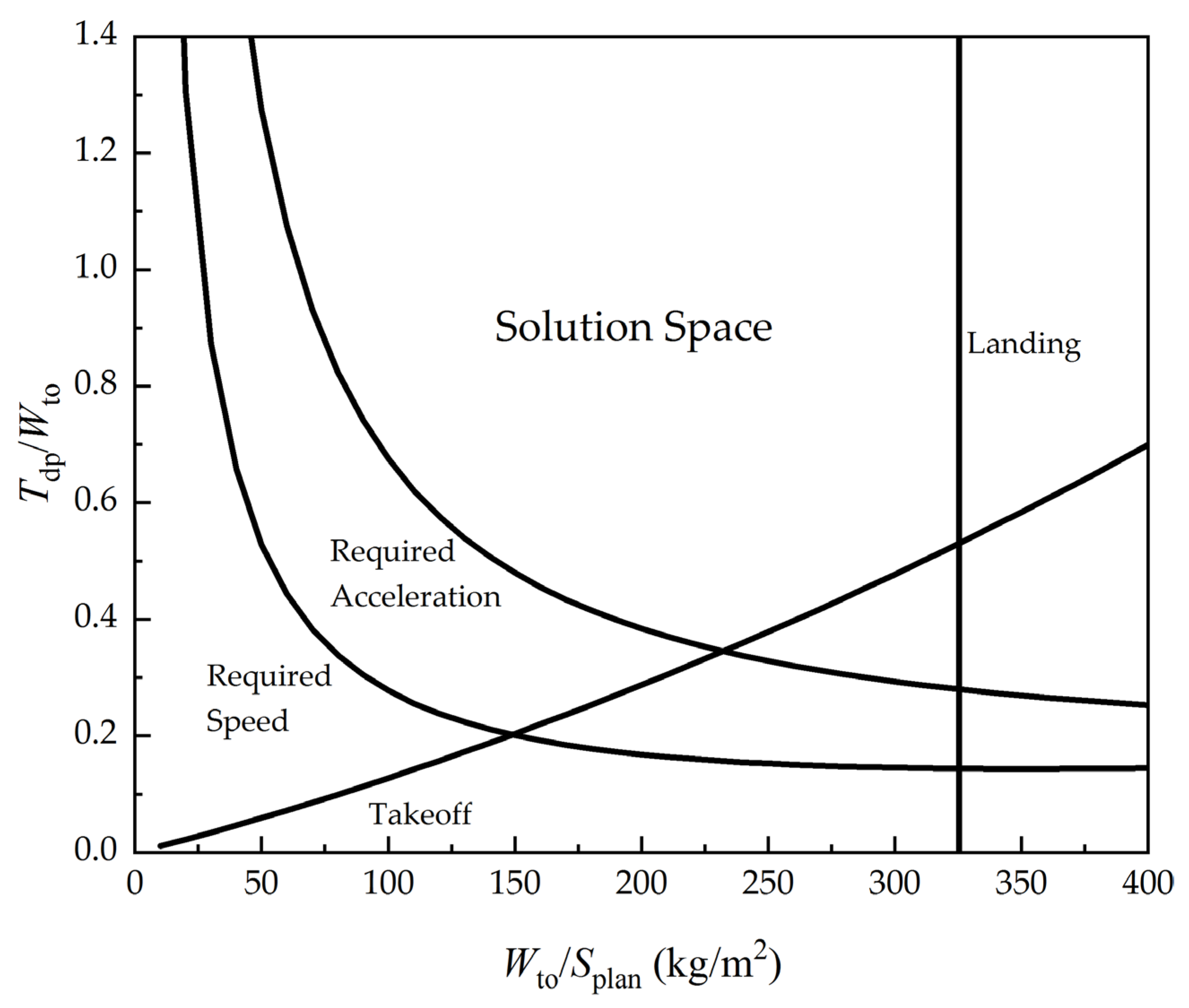
The flight requirements usually include the takeoff and landing distance, rate of climb, maximum cruise speed and altitude, etc. For each of the requirements, a more specific equation can be derived from Equation (14) and a curve of the thrust-to-weight ratio to the wing loading can be drawn, which is also referred to as the “constraint analysis diagram” (see
Figure 4). Any combination of the thrust-to-weight ratio and the wing loading that meets all the requirements falls into the “solution space”. The combination of the thrust-to-weight ratio and the wing loading should be chosen reasonably such that the takeoff gross weight of the aircraft is as minimal as possible.
For the illustrative airbreathing hypersonic aircraft in this study, the wing loading refers to planform loading (Wto/Splan) and is defined as the ratio of Wto to the projected area (Splan). The thrust-to-weight ratio (Tdp/Wto) is defined as the ratio of the thrust at the design point to the takeoff gross weight (Wto). Since the illustrative aircraft has three engine modes (turbojet, ramjet, and scramjet), the thrust-to-weight ratio for each engine mode should be estimated.
3.3. Procedure of Initial Sizing
In the weight/volume estimation, the thrust is needed to estimate the weight and volume of the propulsion system, but the thrust-to-weight ratios are determined by constraint analysis. Therefore, the initial sizing procedure is an iteration between the weight/volume estimation equation and constraint analysis, as depicted in
Figure 5. A further explanation of the initial sizing procedure is presented as follows:
Prepare the input data including mission profile, flight requirements, engine models (see
Section 3.4.1), and assumed aerodynamic characteristics (see
Section 3.4.2).
Assume the engine thrust for the three modes. The assumed thrust is used to estimate the engine weight, volume, and the performance (such as specific impulse, mass flow rate) from the engine models.
Calculate the weight and planform area from weight and volume estimation equations, and the thrust-to-weight ratios and wing loading are consequently calculated.
Find the solution space of thrust-to-weight ratios and wing loading through constraint analysis.
If the combinations of thrust-to-weight ratios and wing loading in step 3 do not fall within the solution space, it means the assumed thrust does not meet some of the flight performance requirements and are updated by the thrust within the solution space.
Repeat step 3 and 4 until the combination of thrust-to-weight ratios and wing loading falls within the solution space.
When the combinations of thrust-to-weight ratios and wing loading fall within the solution space, the assumed thrust meets all of the flight performance requirements. However, this does not mean that the takeoff gross weight is a minimum. A thrust trade is needed to find the minimum takeoff gross weight and will be presented in the results of
Section 4.
In summary of the procedure, the weight, volume, and planform area of the airbreathing hypersonic aircraft are estimated by weight and volume equations for the assumed thrust. A constraint analysis is used to check whether the assumed thrust of three engine modes meets all of the performance requirements. The minimum TOGW is found by the thrust trade.
3.4. Models of the Engine and Aircraft Aerodynamics
From the above initial sizing procedure, the TBCC engine characteristics and the aircraft aerodynamic characteristics should be reasonably assumed in advance. The following subsection will present the models for the estimation of the engine and aerodynamic characteristics.
3.4.1. Model of the TBCC Engine
The engine characteristics required in the initial sizing process include the weight and volume of the engine, thrust, and specific impulse at different speed, altitude, and modes. The selection of design points of the engine greatly affects those characteristics. Since the engine operates in three different modes, three design points are selected accordingly: (1) the design point for the turbojet mode is Ma = 0, H = 0 km; (2) the design point for the ramjet mode is Ma = 3, H = 17.3 km; (3) the design point for scramjet mode is Ma = 8, H = 30 km.
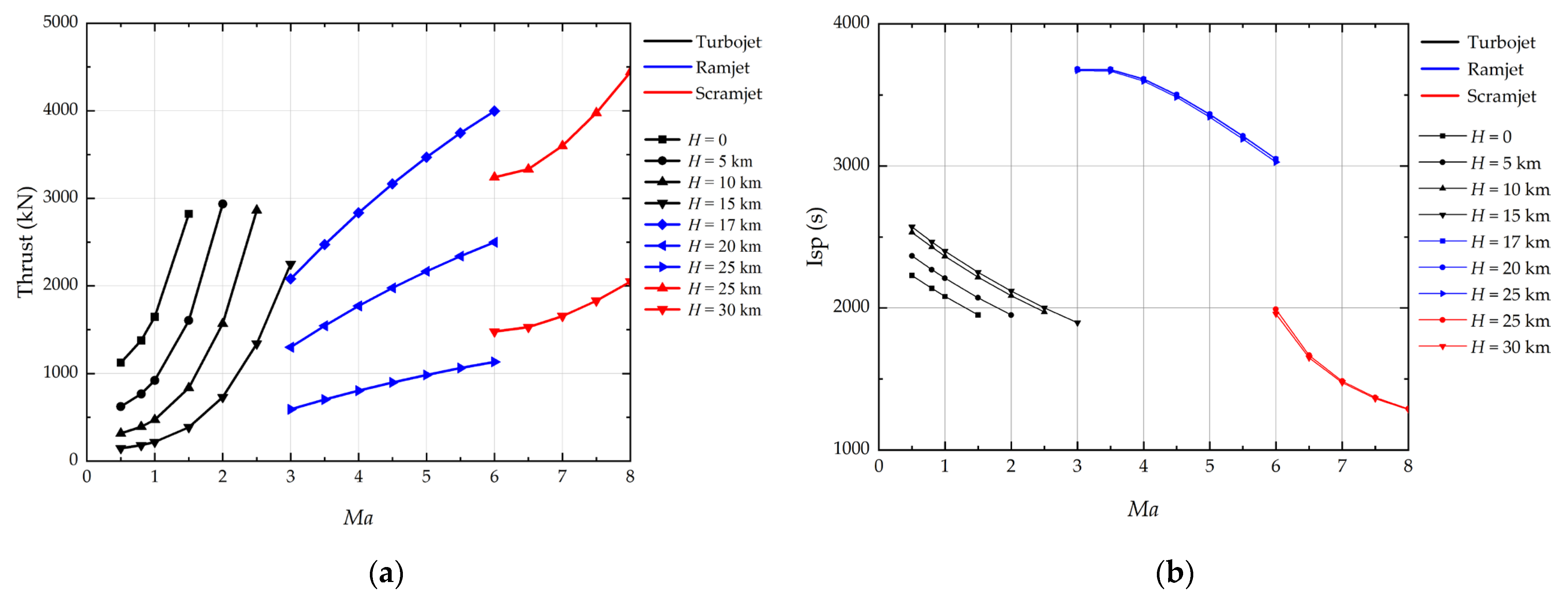
The thrust and specific impulse models for turbojets are from Mattingly [
27]. The thrust and specific impulse corresponding to Mach number and altitude can be predicted from those models, as shown in
Figure 6 (black color).
The weight and volume estimation of the turbojet are estimated empirically from statistical data [
27].
where
Ttj is the thrust of the turbojet at the design point;
Wtj is the weight of the turbojet;
Ltj is the total length of the turbojet, including inlet and exit nozzle; and
Dtj is the diameter of the combustor of the turbojet.
Fleeman [
31] provided the empirical equations of thrust and specific impulse for the ramjets. From those equations, the thrust and specific impulse corresponding to Mach number and altitude for the ramjet can be estimated, as shown in
Figure 6 (blue color).
The weight equation of ramjet is [
15]:
where
Trj is the thrust of ramjet at the design point and
Wrj is the weight of ramjet.
The thrust and specific impulse of the scramjet are estimated by the equations from Chavez and Schmidt [
32], as shown in
Figure 6 (red color).
The weight equation of the scramjet is [
15]:
where
Wsj is the weight of scramjet and
Hsj is the module height. If the section of the pipeline is circular, the module height is equal to its diameter.
As seen in
Section 2.2, the entire propulsion system merges a turbojet and dual-mode ramjet. The weight of the dual-mode ramjet is assumed to be the larger one between the ramjet weight and scramjet weight. The volume of dual-mode ramjet is equal to the inlet area multiplied by the length of pipeline which is assumed to be equal to the length of the turbojet. Because the inlet areas of ramjet and scramjet could be different for different design points, the inlet is assumed to be variable for different modes. The inlet area is the larger one between the inlet area of the ramjet mode and that of scramjet mode.
3.4.2. Model of Aerodynamics Characteristics
Usually, the assumption for aerodynamic characteristics in initial sizing is based on the aerodynamic data of existing aircraft. However, for the airbreathing hypersonic aircraft, the aerodynamic data published are very limited. In this study, the aerodynamic characteristics of the illustrative aircraft are obtained from a rapid prediction method for the given configuration.
For the configuration of the illustrative aircraft as seen in
Figure 3, a rapid aerodynamic prediction program [
33], which is based on Euler equations, is applied to get non-viscous lift and drag. The viscous drag is estimated using the Eckert’s reference temperature methods and the Van Driest II formula [
34].
For the illustrative aircraft, the lift coefficient (
CL) and drag coefficient (
CD) at the different
Ma are estimated and shown in
Figure 7. The data of those coefficients are fitted by the following equations:
where
CLα is lift-curve slope;
CL0 is lift coefficient when α is zero;
CDmin is the minimum drag coefficient;
K′ is the inviscid drag due to lift;
K″ is the viscous drag due to lift;
CLmin is lift coefficient at
CDmin;
;
; and
CD0 is the drag coefficient at zero lift,
.
The above aerodynamics model is used as the input for the initial sizing of the illustrative aircraft.
4. Results
A computer code was developed according to the above method. The initial sizing results of the illustrative aircraft were obtained by use of the computer code.
The results of takeoff gross weight, the total volume, and engine thrust of the illustrative aircraft are summarized in
Table 2. The weight and volume distributions are depicted in
Figure 8. The fuel weight is about one-third of the total weight, and the fuel volume takes up nearly two-thirds of the total volume, which indicates that the fuel has a significant effect on both weight and volume of the illustrative aircraft.
According to constraint analysis, a reasonable thrust-to-weight ratio in the “solution space” should be specified to obtain the minimum takeoff gross weight (TOGW) of the aircraft. For a conventional aircraft, when the wing loading is given, a selection of lower thrust-to-weight ratios in the “solution space” usually leads to a lower TOGW. However, this method is not always effective for the hypersonic aircraft. The reason being that the propulsion system of the hypersonic aircraft has different modes, and each mode is designed for a different flight mission segment. A thrust trade study for the three engine modes (turbojet, ramjet, and scramjet) is needed in order to find the minimum TOGW.
A thrust trade is conducted by creating a carpet plot showing the relationships between the TOGW and the thrust of the three engine modes, as shown in
Figure 9. For the given thrust of the turbojet, the TOGW changes with the thrusts of ramjet and scramjet in a nonlinear manner, which means that fewer thrusts of the ramjet and scramjet do not necessarily result in the minimum TOGW. Additionally, a lower thrust of the turbojet does not necessarily mean a lower TOGW. From
Figure 9, the suitable thrusts of the three engine modes can be selected for a minimal TOGW.
The trend of the carpet plot (
Figure 9) can be explained from two aspects. On one hand, as the thrust increases, the weight and volume of engine increase, which leads to an increase of the TOGW. On the other hand, the fuel consumption changes with the thrust and has a significant impact on the TOGW. The flight profile of the aircraft consists of many segments (see
Figure 1). The fuel consumption (Δ
W) of each segment is calculated by
. The specific impulse (
Isp) is a characteristic parameter of the engine performance that is determined by the flight condition for the given engine modes and is not affected by the thrust (
T). As the thrust increases, the flight time (Δ
t) for the segment will decrease, resulting in the decrease of fuel consumption. However, when the thrust increases beyond a certain value, the increase of the engine weight offsets the profit from the shorter flight time. In this case, the TOGW begins to increase with the thrust.
After the thrust trade, the wing loading and thrust-to-weight ratios for the three engine modes are determined. The wing loading and thrust-to-weight ratios for the three engine modes (turbojet, ramjet, and scramjet) are A (165.7, 0.83), B (165.7, 1.61), and C (165.7, 1.65), as shown in
Figure 10. The combinations of wing loading and thrust-to-weight ratios of the three engine modes are all in the solution space.
5. Sensitivity Analysis
In the weight/volume estimation and constraint analysis, some technology parameters (for instance, the structural index, specific impulse of the engine, and the Küchemann slenderness parameter of the aircraft configuration) need to be assumed. The variation of those technology parameters might have considerable impacts on the takeoff gross weight, the planform area, and the thrust of the aircraft. Such impacts can be understood by sensitivity analysis. The sensitivities of the aircraft weight, size, and thrust to the structural index, specific impulse, and the Küchemann slenderness parameter are conducted for the illustrative aircraft. In the following sensitivity analysis, the takeoff gross weight, planform area, and thrust is normalized by the values in
Table 2.
Figure 11 depicts the takeoff gross weight, planform area, and thrust for the different structural indices. When the structural index increases from 20 kg/m
2 to 24 kg/m
2, the takeoff gross weight increases by 20%, the planform area increases by 11%, and the thrust for three engine modes increases by 15%. It indicates that the structural index has a significant impact on the weight, size, and thrust.
Figure 12 depicts the takeoff gross weight, planform area, and thrust with respect to a change of the specific impulse. Generally, the increase of the specific impulse results in the decrease of fuel consumption. Therefore, the takeoff gross weight, the planform area, and the thrust will decrease. When the specific impulse increases by 20%, the takeoff gross weight decreases by 14%, the planform area decreases by 12%, and the thrust for the three engine modes decreases by 13%, 13%, and 10%.
In the above sensitivity analyses, Küchemann slenderness parameters (τ) are assumed to be given. The τ is closely related to the aircraft configuration, and directly affects the volume and aerodynamic characteristics of the aircraft. For a given planform area, when τ is bigger, the aircraft looks “thicker”, and the maximum lift-to-drag ratio (L/D) becomes lower. If τ is smaller, the wetted area will be smaller, and consequently the L/D will be higher. At the same time, the volume will be smaller and the space for fuel will be smaller as well. It should be noted that both the L/D and the volume will have a significant impact on the aircraft weight.
In this study, the fuselage height of the illustrative aircraft is considered to be varied. The higher height of the fuselage means the larger volume and the larger
τ, and leads to a lower maximum
L/D. For the illustrative aircraft configuration with a variation of
τ, the maximum
L/D during cruise is estimated using the rapid method of
Section 3.4.2. The curve of the maximum
L/D with respect to
τ is shown in
Figure 13.
Figure 14 depicted variations of the takeoff gross weight (TOGW), planform area, and thrust with respect to
τ. As
τ increases, the TOGW begins to decrease. The TOGW reaches a minimum when
τ = 0.08. After
τ is greater than 0.08, the TOGW increases with
τ. The same trends can be observed for variation of the thrust with
τ. However, the planform area changes very slightly after
τ is greater than 0.08. The above observations are explained in the following section.
When the value of τ is very small, the fuselage of the aircraft is very thin, and its volume is very limited. The aircraft volume cannot meet the requirement of the fuel volume. In this case, the size (planform area) of the aircraft needs to be enlarged to increase the aircraft volume. This leads to the increases of the structural weight and thermal protection system (TPS) weight, and consequently results in a large TOGW, and higher required thrusts. Thus, we can see that the planform area, TOGW, and thrust are quite large when τ = 0.03.
The total volume increases as
τ increases if the size (planform area) of the aircraft remains unchanged. The increase of
τ also leads to the decrease of
L/D, which means that fuel consumption would increase. However, the increment of total volume is larger than that of the required fuel volume when
τ increases from 0.03 to 0.08. The size (planform area) of the aircraft should be reduced, resulting in the decrease of the structure weight and the TPS weight that is related to the wetted area. Consequently, the TOGW decreases, as well as the fuel weight. The thrust trend of the turbojet is similar to that of the TOGW. However, the thrust trend of the ramjet and scramjet have a slight difference from the trend of the turbojet. The required thrusts of the ramjet and scramjet decrease to the minimum when τ is around 0.07. When τ increases from 0.07 to 0.08, the thrust of ramjet and scramjet increase, while the turbojet thrust reaches a minimum at τ = 0.8. As shown in
Figure 10, the required thrust of the turbojet is near the constraint lines, but the required thrust of the ramjet and scramjet are far from constraint lines. It means that the required turbojet thrust has a strong relationship with the TOGW and size of the aircraft, while the required thrust of the ramjet and scramjet have weaker relationships. Therefore, the change of the turbojet thrust is similar to the TOGW. However, the thrust of the ramjet and scramjet is also determined by thrust trade. When τ increases from 0.07 to 0.08, the increase of ramjet thrust and scramjet thrust results in a shorter flight time and slight reduction of the fuel consumption, which leads to a slight reduction of the TOGW and size of the aircraft.
After τ is greater than 0.08, total volume increases as well, however, L/D decreases further and the fuel consumption increases significantly. The increment of fuselage volume is nearly equal to that of the required fuel volume. The size (planform area) cannot be reduced further in this case. However, the consumption increments and the enlarged fuselage wetted area lead to the increase of the TOGW, and the required thrust of engine in different modes increases.
6. Summary
Airbreathing hypersonic aircraft are usually powered by a combined cycle engine and require much larger fuel volume. The performance of the engine in different modes, as well as the weight and size of the engine, have a significant effect on the total weight and size of the aircraft. This paper intends to improve the existing initial sizing methods for the airbreathing hypersonic aircraft. The improved method incorporates the empirical models of the combined cycle engines into the initial sizing procedure, so that the accuracy of initial sizing is enhanced, and the thrust trade of the engines can be conducted for the minimal takeoff gross weight of the aircraft.
An illustrative airbreathing hypersonic aircraft is used to present the detailed procedure of the method. The aircraft takeoff gross weight, volume, planform area, and planform loading are estimated by the weight and volume equations for the assumed thrust. A constraint analysis is conducted to verify whether the thrust-to-weight ratios and planform loading are satisfied with performance requirements. If the assumed thrust is not satisfied with the performance requirements, the iterations between the constraint analysis and weight/volume estimation are conducted until the assumed thrust matches to the thrust from the constraint analysis. To find the minimum takeoff gross weight of the aircraft, the thrust trade study is conducted by creating a carpet plot of the takeoff gross weight with respect to the thrust.
The combined cycle engine characteristics and the aircraft aerodynamic characteristics should be reasonably assumed in the initial sizing. The empirical models for the three engine modes (turbojet, ramjet, and scramjet) are used to estimate the weight, volume thrust, and specific impulse of the engine. The aerodynamic characteristics are assumed based on the illustrative aircraft configuration using a rapid aerodynamic prediction method.
Some technology parameters such as the structural index, specific impulse, and the Küchemann slenderness parameter might have considerable impacts on the takeoff gross weight, planform area, and thrust. A sensitivity analysis of the weight, size, and thrust in relation to those technology parameters can help us understand such impacts. It is worth noting that there exists an optimal Küchemann slenderness parameter for the minimum takeoff gross weight for a given configuration.
In future research, the internal layout issue in the hypersonic aircraft design is worth studying. Intelligence algorithms [
35] might be helpful for studying this issue. Multidisciplinary analysis and optimization integrated with higher fidelity models of aerodynamics, propulsion systems, and weights should be applied in a conceptual design of hypersonic airbreathing aircraft. Multidisciplinary analysis and optimization is an essential method for the conceptual design of airbreathing hypersonic aircraft and will significantly enhance the design effectiveness [
36].


