1. Introduction
The study of Mars provides deeper insight into the evolution of the universe and enables a better prediction of the environmental conditions for future Mars missions. Currently, there are three operational rovers, eight orbiters, one lander, and the Ingenuity helicopter investigating the planet. Nevertheless, our understanding of Mars’ evolution is still limited. Orbiters cover large areas and provide images of the planet’s surface with a resolution limited to a few meters, while rovers have a relatively short range. In contrast, an aircraft flying at a low altitude above the surface of Mars will carry out scientific research, mapping an area several orders of magnitude larger than that covered by a rover, with a resolution much higher than the resolution offered by modern satellites. In addition, it will gather atmospheric data at different altitudes. The major advantage of an airplane, compared to a helicopter, is its larger range and/or payload capacity. Therefore, there is a wide range of possible applications for a fixed-wing flying vehicle on Mars.
The most significant scientific goals of the Mars missions are:
The search for signs of life on Mars in the past and at present;
The study of the geochemical environment of the surface and in the subsurface layer;
The study of the Martian atmosphere and surface-atmosphere interaction.
The earliest of the conceptual Martian airplane projects was the Mini-Sniffer, an aircraft with a wingspan of 6.7 m, powered by a hydrazine engine [
1]. Since then, significant improvements related to aerodynamic design, engine concepts, energy storage, and materials have expanded the range of options for Martian unmanned aerial vehicles. Among the proposed concepts, the most famous are the ARES (Aerial Photography of the Environment on a Regional Scale) from the NASA Langley Research Center [
2] and the Remotely Piloted Vehicle for Mars Exploration [
3]. Other projects involving Martian unmanned aerial vehicles based on a wide variety of concepts have been studied, such as gliders [
4,
5], including those with inflatable wings [
6,
7,
8], as well as helicopters [
9] and flying insect robots [
10].
In airplane projects, the design output is strongly dependent on the mission requirements. These requirements include the mission profile and payload description, as well as all relevant limitations and design parameters related to the expected operational conditions. For a Martian airplane, the design requirements can be subdivided into three categories:
Requirements related to the airplane’s delivery to the Martian surface;
Requirements related to the Martian conditions (atmosphere and climate);
Requirements related to the payload parameters and operating conditions.
The structure of this paper is as follows. First, we outline the factors affecting the airplane during its delivery to the target site on Mars (
Section 2) and when the airplane is exposed to the Martian conditions (
Section 3). After that, we outline several alternative mission scenarios and profiles (
Section 4 and
Section 5). A summary of the design requirements and limitations is presented in
Section 6, followed by a series of design concepts based on these requirements (
Section 7). The results of the present study are discussed in the conclusion (
Section 8).
2. A Mars Mission with an Unmanned Aerial Vehicle as a Payload
This section discusses the conditions to which a Martian unmanned aerial vehicle (UAV) is exposed during delivery to the target site on Mars. The delivery scenario is based on the programs designed for the previous Mars missions.
2.1. UAV’s Delivery to the Upper Edge of the Martian Atmosphere
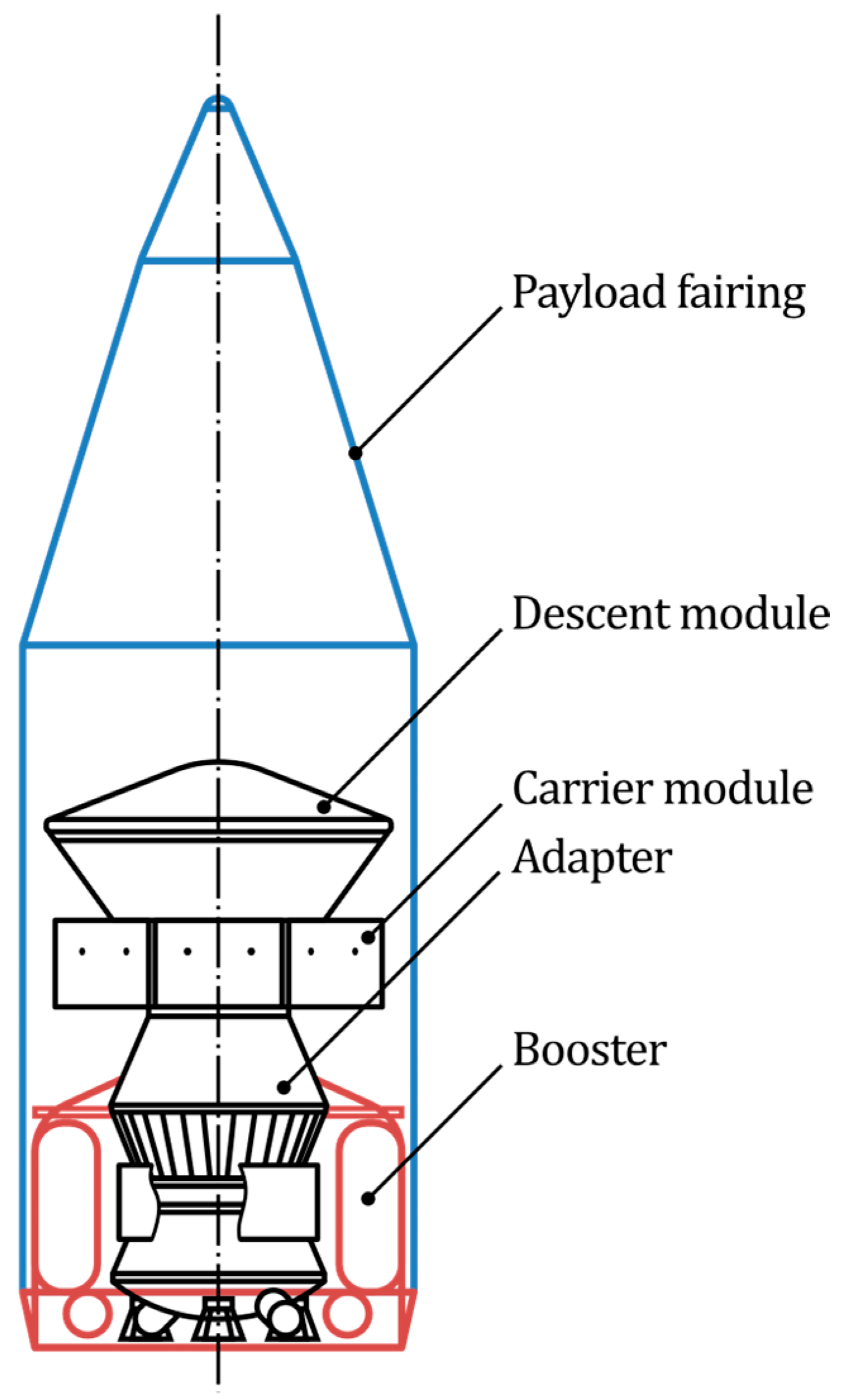
The payload assembly includes the spacecraft (consisting of the descent and carrier modules), a booster, an adapter, and the payload fairing (
Figure 1).
The payload is mounted in the descent module, which has an axis-symmetric, ballistic design. Presumably, the aircraft can be considered as a secondary payload, occupying the space left after the placement of the primary payload, which usually includes a lander, as well as a power system, a thermal control system, instruments, and solar arrays.
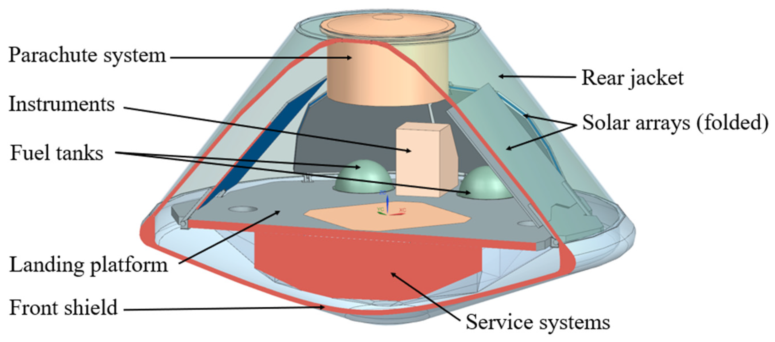
Figure 2 shows the general layout of a descent module with no payload apart from the landing platform and scientific and service instruments arranged inside it.
To set the spacecraft on the departure trajectory to Mars, a four-stage injection program is used (
Figure 3). The payload fairing is dropped during the operation of the third stage of the launcher.
After beginning the departure trajectory to Mars, the spacecraft consisting of the carrier and landing modules separates from the orbital unit. The total launch duration from the carrier launch to the spacecraft’s separation is approximately 4.5 h.
2.2. Entry and Descent Program
A potential entry and descent program and two possible UAV flight profiles are shown in
Figure 4. The entry and descent program is based on that used in the ExoMars mission [
11].
The separation of the spin-stabilized descent module from the carrier module occurs when approaching Mars. The status vector is formed by the carrier module.
Mars has a rather thin atmosphere, which calls for the use of a powered descent system in the final stage of landing.
The descent module landing program consists of several stages:
The extra-atmospheric stage, starting with separation from the carrier module and ending just before entry into the Martian atmosphere. The upper level of the atmosphere is assumed to be 120 km above the Martian surface.
The aerodynamic deceleration stage, starting at a height of 120 km and ending before the parachute system’s deployment.
Deceleration using the parachute system, ending with the separation of the landing module from the rear jacket with the parachute system mounted on it.
The powered deceleration of the landing platform—from the separation of the landing platform from the rear jacket to the touchdown of the landing platform supports on the surface of Mars.
During aerodynamic deceleration, the aeroshell speed decreases from the entry speed of approximately 5800 m/s to the values acceptable for the deployment of the supersonic parachute (M = 2). The maximum dynamic pressure varies from 5600 to 9500 Pa and is achieved at altitudes of 25 to 33 km. The maximum load factor experienced by the landing module approaches 9.
A supersonic parachute with a diameter of 15 m decelerates the landing module to a Mach number less than 0.8, after which it is separated from the landing module and a subsonic parachute with a diameter of 35 m is deployed. After filling the dome of the subsonic parachute, the front shield is separated from the landing module. In the final stage, the powered deceleration system ensures the platform landing at a vertical speed of up to 1 m/s.
Depending on its vertical takeoff and landing (VTOL) capability, the UAV can either be released from the descent module once the rear jacket (with the parachute system) is separated or perform a vertical takeoff from the landing platform resting on the Mars surface.
If the aircraft is not capable of VTOL, it must be released at the greatest height possible to ensure a successful pullup maneuver and the completion of the mission profile. The release altitude will depend on the parachute’s efficiency, the descent trajectory, and the aircraft properties, including the Mach number limit, mass, and aerodynamic characteristics [
12].
Parachuting introduces some issues:
The crosswind effect on the descent module movement (the horizontal wind speed in the atmospheric boundary layer can reach 25 m/s [
11]);
A parachute with a landing platform on slings is a pendulum system. The amplitude of the pendulum oscillations depends on the perturbations during the parachute’s deployment. By the moment of separation of the rear jacket with the parachute system attached to it, the amplitude of the oscillations, with respect to the angle of attack and sideslip, can be up to 15°, with the angular velocity reaching 7°/s [
11].
To facilitate the release of the UAV, the control system must dump the angular velocity of the descent module around the longitudinal axis.
Murray and Tartabini [
12] reported that an 18 kg Martian airplane with a Mach number constraint of 0.8 requires a 5000–3000 m altitude margin to successfully perform a pullup maneuver. In this study, the pullup altitude margin depends on the landing site and the aircraft aerodynamic characteristics.
3. External Conditions during the Launch, Cruise, Entry, Descent, and Operation on Mars
3.1. External Factors Affecting the Martian UAV Design for Delivery to Mars
The descent module, throughout its flight program, is subjected to a number of external factors [
11].
Carrier launch-related factors:
Cruise-related factors:
Outer space radiation;
low temperature.
Descent-related factors:
mechanical loading;
high-temperature.
Martian environment-related factors:
The means required to mitigate the delivery-related factors for a Martian UAV as a secondary mission payload are as follows:
3.2. Radiation
On the Earth-Mars trajectory, the spacecraft is exposed to the following forms of ionizing radiation from outer space [
11]:
The protons and ions of solar cosmic rays;
The protons and heavy nuclei of galactic cosmic rays;
The protons and electrons of the Earth’s radiation belts.
For thermal control in space missions, it is common to use thermal units based on plutonium-238 dioxide. Energy in these thermal units is produced through the spontaneous nuclear decay of plutonium isotopes, the side effect of which is a neutron flux with a characteristic fission spectrum. This neutron radiation creates an additional load on the electronic equipment because it affects the optical, electrical, and mechanical properties of matter.
Once the airplane is delivered to Mars, the radiation load decreases by 70% due to its absorption by the Martian atmosphere.
If the coefficient of resistance of the device to the structural volumetric damage, in terms of the total non-ionization dose, is less than three, the device can be damaged by neutron radiation from the thermal units [
11]. In a case of insufficient radiation resistance of the electronic components, it is necessary to replace the component with a more resistant one, to relocate the device (increasing the distance from thermal units, shielding with other devices), or, in extreme cases, to use radiation protection methods to ensure its durability.
3.3. Rugged Terrain
Due to Mars’ uneven and rugged terrain, the fixed wing Mars airplane missions typically begin by deploying the airplane and end with an uncontrolled crash onto the planet’s surface. Therefore, the only option for a Mars aircraft lander is to be capable of performing a vertical takeoff and landing.
3.4. Dust Storms and Atmospheric Turbulence
Other Mars special atmospheric properties and processes that drive Mars aircraft design include the following:
Dust plays a key role in determining the current climate of Mars and is suspected to have had a major influence on the evolution of the surface and the history of the climatic conditions on the planet [
13].
Local dust storms occur at almost all latitudes and throughout the year. However, they have been observed to occur most frequently in the approximate latitude belt from 10° to 20° N and 20° to 40° S, with more dust clouds seen in the south than in the north, the majority of which occur during the southern spring.
Due to flows with a transverse velocity gradient, the entire near-surface atmosphere is turbulent. The presence of relatively small dust particles in the near-surface flow causes an increase in the velocity gradient and an increase in particle detachment from the surface, increasing the amount of dust transferred to the atmosphere [
14]. The turbulence intensity in the Martian atmosphere can be as high as 20%, which must be incorporated into the model of the atmosphere used for UAV simulations.
3.5. Temperature
The ambient temperature on Mars’ surface ranges from −130 to −5 °C, which calls for a thermal control system onboard the aircraft to ensure the normal operation of the instruments and power plant.
The methods for thermal control used in spacecraft include the following:
Electric heaters;
Thermoregulating coatings;
Screen vacuum thermal insulation;
Structural elements that provide the necessary thermal resistance.
4. LEMFEV Mission Objectives
Aircraft can implement modes of observation that are not achievable using rovers and landers. For this project, such targets can be canyons and craters, the walls of which might unveil a million years of Mars’ history. Among them, Hellas Planitia, the lowest part at the Mars surface, can be highlighted (
Section 4.1).
Section 4.2 discusses the planetary boundary layer as a potential alternative target for a Martian UAV.
4.1. Hellas Planitia
Hellas Planitia is a roughly elliptic impact crater approximately 3000 km long and 1500 km wide, located in the southern hemisphere of Mars. It reaches a minimum depth of 7.5 km in its north-west corner, which is the lowest point on the entire surface of Mars. The atmospheric pressure at the bottom is expected to be as high as 1155 Pa. This is 89% higher than the pressure at the topographical datum (610 Pa). On the one hand, this allows one to reduce the cruising speed of an aircraft. On the other hand, the atmospheric pressure at the bottom of the Hellas basin might allow water to persist in a liquid state [
15]. For orbiters, this is a difficult area for investigation because of the atmosphere density and dust.
In this study, we offer the walls of the Hellas Planitia crater as a potential scientific target for the Martian aircraft for the following reasons:
4.2. Mars Atmospheric Boundary Layer
The Martian planetary boundary layer comprises the lowest 1–10 km of the atmosphere, within which surface-driven intense convection may take place.
A clear and quantitative understanding of this part of the atmosphere and the way in which it interacts with the surface and atmosphere are important for understanding the past, present, and future Martian environment. This will enable scientists to make reliable predictions of the environmental conditions encountered during spacecraft entries and operations for mission safety and efficient design.
Landers and rovers operating on the Mars surface have provided pressure and temperature time series, as well as wind speed and direction data. If these quantities are measured at several levels above the surface, it will be possible to estimate their gradients and, thus, to evaluate vertical fluxes. Orbital observations have a limited capacity to probe the lowest layers of the atmosphere.
The direct observational measurements within the Martian boundary layer remain relatively sparse. The vast majority of in situ measurements on Mars have been obtained at altitudes slightly higher than 1 m.
It has been suggested [
14] that future instrumental campaigns related to the study of the boundary layer will need to focus on a series of objectives, including the following:
The first objective can be met either by increasing the number of probes or by using an airborne flying vehicle with an extended range, equipped with an appropriate set of instruments. The second objective calls for a VTOL vehicle (helicopter or convertible airplane) capable of performing flights at the required frequency.
5. LEMFEV Mission Scenarios
An aircraft intended for Mars exploration can be designed to perform single-flight or multiple-flight missions (
Figure 4).
A single-flight aircraft will conduct in-flight measurements and, if equipped with a device to perform a single controlled vertical landing, it will also serve as a lander, measuring parameters of interest on the surface.
A VTOL vehicle can either perform profile measurements in the planetary boundary layer on the required timescales or carry instruments to the prescribed sites and perform on-surface measurements. The first option will allow for the determination of turbulent and radiative fluxes within the lowest 2–5 km of the atmosphere. Petrosyan et al. [
14] outlined that such measurements need to allow for the strong temporal variations anticipated in this part of the atmosphere. The second option will widen the geographical and temporal coverage of measurements.
The scientific payload sets proposed for different in-flight and on-surface measurements are reviewed in
Table 1 and
Table 2. Instruments working in the flight phase are mainly dedicated to the study of the underlaying surface. A geological site is, in general, characterized by cameras. For a more precise investigation of surface matter properties, the payload may include an infrared (IR) spectrometer. Small topography features are scanned using LIDAR in detail due to the proximity of the vehicle to the Mars surface. Ground-penetrating radar and a radiometer are two instruments that allow one to study the inner structure of the near-surface layer. The aircraft may require a meteorological package to track local changes in the environment at different altitudes (measurements of temperature, pressure, wind, and humidity).
After landing, a detailed analysis of the site becomes the primary goal, using the instruments. Cameras are used to scan the environment and to determine potential targets for the study of minerology. The combination of infrared and Raman and/or LIES spectrometry enables a detailed composition study of the chosen targets. On the surface, meteorological sensors are dedicated to long-term atmospheric monitoring.
6. LEMFEV Specifications
6.1. Mission Specifications
A Martian UAV mission specification includes the following:
Design parameters: delivery-related parameters (
Table 3) and operating conditions (
Table 4);
Instruments’ properties (mass, volume, input voltage, operating temperature range) (
Table 1 and
Table 2);
The mission profile: flight velocity, altitude, and range (
Table 5).
6.2. Additional Considerations
6.2.1. Planetary Protection
According to the Committee on Space Research requirements, for category IVa expeditions, the microbiological contamination of the surface of landers, at the ends of their sides, should not exceed 300 bacterial spores per square meter and 5105 bacterial spores (on the surface and in volume) per lander before launch. The UAV and its components must allow for cleaning using one of the following methods [
11]:
Sterilization (gamma radiation or electron beam radiation with energy up to 10 MeV, ultraviolet radiation during assembly, hydrogen peroxide vapor, thermal);
Decontamination with disinfectants (alcohol, sporocides) applied to those elements for which it is impossible to choose a sterilization mode without deteriorating their quality.
6.2.2. Aerodynamics
For the Martian conditions, an optimized airfoil is likely to be similar to an Ishii airfoil [
16], with
at
and
(
), where the definitions are as follows:
is the lift coefficient corresponding to the maximum lift-to-drag ratio;
is the maximum lift coefficient;
is the angle of attack, degrees;
is the Reynolds number;
is the Mach number.
Due to the low ambient temperature, the operating Reynolds number and speed of sound will be low, which will have the consequence of strong viscosity-compressibility interactions, which are challenging to model both experimentally and numerically.
6.2.3. UAV’s Folded Size
For delivery to Mars, the UAV must be stowed in an aeroshell, and the aeroshell geometry, along with the minimum possible number of unfold events (for a rigid wing), limit the wingspan.
7. LEMFEV Configurations
For this science Martian UAV, some baseline configurations and the associated missions are presented in
Table 5.
The propulsion options potentially feasible for Martian conditions include the following:
In the Earth’s conditions, a propeller is a more efficient means of generating thrust than a rocket for a low-speed, high-altitude airplane. For Mars application, a number of propeller-based propulsion systems were also considered.
The options considered for driving the propeller in Martian conditions included the following:
An electric motor powered by batteries (consisting of batteries, a propeller, a gearbox, and an electric motor);
An electric motor powered by a fuel cell;
The Akkerman-type hydrazine engine (consisting of a hydrazine engine and piston expander).
8. Conclusions
The number of constraints shaping the feasible design area of a Martian aircraft is greater than that of an Earth aircraft. In addition to more typical constraints, the feasible design area for a Martian aircraft may be limited by the following aspects:
The aeroshell shape and size, with the consequence of rigid or inflatable unconventional structures posing a high risk;
The coupling of viscosity and compressibility effects, which is difficult to predict;
The launch and entry g-load, with the consequence of an increased structural weight;
Low temperatures and radiation, with added weight due to the protection and heating systems;
The need to ensure the specific conditions for the onboard scientific instrumentation (this may limit, e.g., the flight altitude and speed); this also implies that the combustion exhaust products must not contaminate scientific measurements;
The aeroshell center-of-gravity constraint, which may also exert a significant influence on the “big” decisions, like that of the aerodynamic layout selection.
Atmospheric turbulence and dust;
The target operating site, altitude, and season.
Potential scientific missions for a Martian aircraft include crater or boundary layer exploration, which can be performed within either a single-flight or a multiple-flight scenario. The measurements can be obtained either in flight or on the surface. The LEMFEV configuration will be defined largely by the power plant type and prescribed flight profile.
Author Contributions
Conceptualization, E.K.; methodology, E.K., T.K., D.E. and K.A.; investigation, E.K., T.K., D.E. and K.A.; resources, D.G.; data curation, E.K., T.K. and D.G.; writing—original draft preparation, E.K.; writing—review and editing, E.K., D.E. and K.A.; visualization, E.K. and T.K.; supervision, D.G.; project administration, E.K. and D.G.; funding acquisition, D.G. All authors have read and agreed to the published version of the manuscript.
Funding
This work is being financially supported by the Russian Science Foundation under the agreement № 22-49-02047 from 9 March 2022.
Data Availability Statement
The research data are available upon request.
Conflicts of Interest
The authors declare no conflict of interest.
References
- Reed, R.D. High-flying mini-sniffer rpv—Mars bound. Astronaut. Aeronaut. 1978, 16, 78A38521. [Google Scholar]
- Gasbarre, J.F.; Dillman, R.A. Preliminary Design and Analysis of the ARES Atmospheric Flight Vehicle Thermal Control System; SAE Technical Paper: Warrendale, PA, USA, 2003. [Google Scholar]
- NASA. A Concept Study of a Remotely Piloted Vehicle for Mars Exploration; NASA: Greenbelt, MD, USA, 2013.
- Walker, D.D. Preliminary Design, Flight Simulation, and Task Evaluation of a Mars Airplane. Master’s Thesis, University of Tennessee, Knoxville, TN, USA, 2008. [Google Scholar]
- Lewis, R.; Clarke, V.C.; Kerem, A. A mars airplane … oh really. In Proceedings of the 17th Aerospace Sciences Meeting, New Orleans, LA, USA, 15–17 January 1979. [Google Scholar]
- Kearns, J.; Usui, M.; Smith, S.; Scarborough, S.; Smith, T.; Cadogan, D. Development of UV-curable inflatable wings for low-density flight applications. In Proceedings of the 45th AIAA/ASME/ASCE/AHS/ASC Structures, Structural Dynamics & Materials Conference, Palm Springs, CA, USA, 19–22 April 2004. [Google Scholar]
- Jacob, J.; Lumpp, J.; Smith, S.; Smith, W. Multidisciplinary design experience of a high altitude inflatable wing UAV for aerospace work force development. In Proceedings of the 44th AIAA Aerospace Sciences Meeting and Exhibit, Reno, NV, USA, 9–12 January 2006. [Google Scholar]
- Ayele, W.; Maldonado, V. Conceptual Design of a Robotic Ground-Aerial Vehicle with an Aeroelastic Wing Model for Mars Planetary Exploration. Aerospace 2023, 10, 404. [Google Scholar] [CrossRef]
- Benito, J.; Noyes, C.; Shotwell, R.; Karp, A.; Nakazono, B.; Singh, G.; Kim, H.; Schoenenberger, M.; Korzun, A.; Lobbia, M. Brandeau/Hybrid propulsion mars ascent vehicle concept flight performance analysis. In Proceedings of the 2017 IEEE Aerospace Conference, Big Sky, MT, USA, 4–11 March 2017; pp. 1–13. [Google Scholar]
- Bar-Cohen, Y.; Colozza, A.J.; Badescu, M.; Sherrit, S.; Bao, X. Biomimetic flying swarm of entomopters for mars extreme terrain science investigations. Concepts Approaches Mars Explor. 2012, 1679, 4075. [Google Scholar]
- Efanov, V.V. Russian Segment of the International Space Expedition ExoMars; Springer: Berlin/Heidelberg, Germany, 2022. [Google Scholar]
- Murray, J.; Tartabini, P. Development of a Mars airplane entry, descent, and flight trajectory. In Proceedings of the 39th Aerospace Sciences Meeting and Exhibit, Reno, NV, USA, 8–11 January 2001. [Google Scholar] [CrossRef]
- Appelbaum, J.; Landis, G.A.; Sherman, I. Solar radiation on Mars. Update 1991. Sol. Energy 1990, 50, 35–51. [Google Scholar] [CrossRef]
- Petrosyan, A.; Galperin, B.; Larsen, S.E.; Lewis, S.R.; Määttänen, A.; Read, P.L.; Rennó, N.; Rogberg, L.P.; Savijärvi, H.; Siili, T.; et al. The Martian atmospheric boundary layer. Rev. Geophys. 2011, 49, RG3005. [Google Scholar] [CrossRef]
- Zalewska, N. Hellas Planitia as a potential site of sedimentary minerals. Planet. Space Sci. 2013, 78, 25–32. [Google Scholar] [CrossRef]
- Anyoji, M.; Hamada, D. High-performance airfoil with low Reynolds number dependence on aerodynamic characteristics. Fluid Mech. Res. Int. J. 2019, 3, 76–80. [Google Scholar] [CrossRef]
| Disclaimer/Publisher’s Note: The statements, opinions and data contained in all publications are solely those of the individual author(s) and contributor(s) and not of MDPI and/or the editor(s). MDPI and/or the editor(s) disclaim responsibility for any injury to people or property resulting from any ideas, methods, instructions or products referred to in the content. |
© 2023 by the authors. Licensee MDPI, Basel, Switzerland. This article is an open access article distributed under the terms and conditions of the Creative Commons Attribution (CC BY) license (https://creativecommons.org/licenses/by/4.0/).

 ,
, 


