Article

Analytical Formulations for Nitrogen Oxides Emissions Estimation of an Air Turbo-Rocket Engine Using Hydrogen

1
Politecnico di Torino, Corso Duca degli Abruzzi 24, 10129 Turin, Italy
2
Italian Aerospace Research Centre, Via Maiorise, 81043 Capua, Italy
*
Author to whom correspondence should be addressed.
Aerospace 2023, 10(11), 909; https://doi.org/10.3390/aerospace10110909
Submission received: 23 September 2023 / Revised: 14 October 2023 / Accepted: 23 October 2023 / Published: 25 October 2023

Abstract

:
According to the latest report of the Intergovernmental Panel on climate change, aviation contributes to only about 2% to anthropogenic global greenhouse gas (GHG) emissions. However, in view of the growing market demand and the dramatic reductions in other transport sectors, including maritime and automotive, the aviation sector’s percentage impact on global GHG emissions is expected to reach 50% of the transport share by 2040. High-speed aviation exploiting liquid hydrogen as the propellant can represent a valuable solution toward the decarbonization of the sector. However, to avoid jeopardizing the dream of a new generation of high-speed aircraft, it will be necessary to introduce non-CO2 emissions estimations beginning with the design process. To unlock the possibility of anticipating the nitrogen oxides emissions estimation, the authors developed the hydrogen and high-speed P3-T3 methodology (H2-P3T3), an evolution of the widely used P3-T3 method, properly conceived to support (i) innovative air-breathing propulsive systems for supersonic and hypersonic flights and (ii) greener fuels, such as hydrogen. This paper presents a step-by-step approach to developing novel analytical formulations customized for an Air Turbo-Rocket engine and discusses the discovered correlation of nitrogen oxides production with the fuel-to-air ratio (FAR), the Mach number, and the Damköhler number (Da), the last being a nondimensional variable directly related to hydrogen/air combustion, considering the matching between the residence time and the ignition delay times. The most complete formulation allows for reduction in the prediction errors below 5%.

1. Introduction

According to the latest report of the Intergovernmental Panel on climate change (IPCC), aviation contributes only about 2% to anthropogenic global greenhouse gas (GHG) emissions [1,2,3]. Depending on the fuels and technologies adopted, emissions from aircraft include carbon dioxide (CO2), nitrogen oxides (NOx), sulfur aerosols, compounds, particulates, and water vapor leading to the formation of contrails, which contribute to radiative forcing and global warming. Despite the small percentage of GHG emissions, the aviation sector is considered one that is difficult to abate and requires a revolution. Major industries, including the energy and automotive, are taking steps toward decarbonization, but aviation’s emissions continue to increase. Aircraft efficiency is improving, with fuel burn decreasing at approximately 1%/year. Looking at the net effect, Roland Berger experts [4] estimate that aviation may be producing as much as 24% of global CO2 emissions by 2050, compared to roughly 3% today. Even with hypothetical acceleration in improvements, considering the higher emission reduction potentials in other sectors, aviation may become the most important contributor to global GHG emissions. According to Figure 1 and Figure 2, in less than 10 years from now, pressure on ship operators and airlines would dramatically increase, since the relative contributions of these two transport modes will start to dominate the total GHG emissions of the transport sector in Europe.
In this highly challenging scenario, universities, research centers, and industries are exploring various pathways, including the adoption of greener modes of operation. Despite the modern focus on electrification and batteries for power storage, hydrogen is a genuine contender for aviation [4], especially for high-speed civil commercial aircraft where three times higher energy content per unit mass with respect to kerosene makes hydrogen the most desirable energy carrier. Hydrogen combustion guarantees a complete decarbonization of flights; however, non-CO2 emissions and their climate impact potential must be carefully investigated. To avoid jeopardizing the dream of a new generation of high-speed aircraft, it will be necessary to introduce emission estimations at the beginning of the design process, to verify compliance with future emission requirements during conceptual design. Specifically, this paper describes a novel analytical formulation for nitrogen oxides emissions estimation for an air turbo-rocket (ATR) engine using hydrogen. In detail, to unlock the possibility to anticipate the environmental sustainability assessment, the authors have developed the hydrogen and high-speed P3-T3 formulation (H2-P3T3) to extend the widely used P3-T3 methodology [7], which covers (i) innovative air-breathing propulsive systems developed to support supersonic and hypersonic flights and (ii) greener fuels, such as hydrogen. Please note that the H2 in the acronym indicates that the newly proposed methodology works both for hydrogen-fueled and high-speed engines. In detail, by coupling simplified but accurate models of propulsive systems and related databases with 0D chemical-kinetic combustion models, the authors have derived novel analytical formulations capable to predict NOx emissions (as emission indices in grams of emitted species per kg of hydrogen burned). Different from the original formulation, where the NOx emission indices appeared correlated only to the temperature and pressure at the beginning of the inlet of the combustion chamber, the novel formulations described in this paper show how the exploitation of hydrogen as fuel and the higher flight speed suggest additional correlations. However, to be exploitable at the conceptual design level, these novel formulations still require a minimum set of input data (in line with the information usually available at this stage) and minimal computational resources (to be compatible with the fast design loops), still maintaining a high degree of reliability (to support decisions with very high committed costs). To improve the original formulation, a new set of more appropriate correlating parameters was investigated. Looking at NOx minimization strategies, the authors have defined a preliminary set of variables (i.e., fuel flow rate, air flow rate, aircraft speed, ignition delay time, and residence time). Then, through an in-depth investigation of the results from the chemical-kinetic analyses and an assessment of the most commonly adopted strategies for NOx minimization, three main additional correlating parameters were discovered and added to the formulations: the fuel-to-air ratio (FAR), the Mach number, and the Damköhler number (Da), the last being a nondimensional variable directly related to hydrogen/air combustion, which considers the matching between the residence time and the ignition delay times.
The paper starts with an in-depth assessment of nitrogen oxides emission prediction techniques, clearly stating the benefits and showstoppers of their exploitation for high-speed air-breathing engines using hydrogen. For the first time, a comprehensive review of emissions estimation techniques and their applicability beyond traditional subsonic aeroengines and fuels is reported (Section 2). Then, Section 3 provides the readers with useful insights on the case study: the air turbo-rocket engine configuration developed and optimized owing to a series of EC-funded projects on high-speed. Specifically, Section 3 reports the propulsive and emissive databases obtained at the end of the H2020 STRATOFLY project and currently exploited inside its follow-up, the H2020 MORE&LESS project. The data reported in this Section 3 represent a clear added value of the paper, providing important insights on the ATR and its performance in very different operating conditions, from takeoff up to cruise Mach numbers, covering a wide range of Mach numbers from 0.3 to 4. Section 4 describes the newly derived H2-P3T3 methodology in a step-by-step approach, starting from the original methodology and formulation to the definition of the new ones. Many innovative aspects can be highlighted in Section 4:
  • The H2-P3T3 method follows an approach similar to the original P3-T3 method and allows the prediction of in-flight emissions, knowing the emissions at sea-level conditions together with the ratios of the flight-level and sea-level conditions of the pressure and fuel-to-air ratio at the inlet of the combustion chamber. However, the need to introduce new parameters (i.e., Da) in the analytical formulations to better represent the high-speed hydrogen combustion, modifies the original method, requiring the definition of additional sea-level trends for new variables, including the ignition delay time (i.e., the time elapsing between the start of injection and the start of combustion) and the residence time (i.e., the time spent by the reacting flow inside the thrust chamber).
  • While the original P3-T3 method consists of a single analytical formulation with tuneable parameters to effectively represent different engine architectures, the new H2-P3T3 method encompasses three different formulations for the same engine architecture (ATR). The different formulations provide the user with different levels of prediction accuracy and can thus be applied at different stages in the design process, increasing the flexibility in the method.
  • The introduction of new correlated factors to improve the analytical formulations is based on an in-depth investigation into the results of the chemical-kinetic analyses coupled with the assessment of the most commonly adopted strategies for NOx minimization in the case of hydrogen-based combustion in high-speed aviation propulsive systems.
  • This section reveals an important scientific finding: the emissions of nitrogen oxides from a high-speed engine using hydrogen are well correlated to the Da number. A variation in Da number is usually due to a variation in the residence time of the reacting flow in the combustion chamber, which may lead to a temperature variation in the combustor, thus resulting in a variation in NOx emissions.
  • While the formulations are strictly related to the architecture of the analyzed engine, the proposed H2-P3T3 method has a more general validity and can be used as a baseline for developing additional analytical formulations to better represent different engine architectures and technologies.

2. State of the Art in NOx Emissions Modeling for Aeronautical Applications

According to [7], nitrogen oxides emission prediction techniques can be grouped in five main families: (i) correlation-based models, (ii) P3T3 methods, (iii) fuel-flow methods, (iv) simplified physics-based models, and (iv) high-fidelity simulations. After in-depth investigations, the authors selected the P3T3 method as a baseline for the development of new predictive analytical formulations. Hereafter, the reader can find a brief recap and useful references for each of the various NOx emissions prediction techniques along with a discussion on their applicability in the conceptual design of high-speed aircraft powered with liquid hydrogen.

2.1. Correlation-Based Methods

Correlation-based methods include both empirical and semiempirical models. They are built using experimental data from a specific engine, which usually include primary variables, namely, combustor inlet pressure (P3) and temperature (T3), temperature after combustion (T4), fuel-to-air ratio (FAR), water-to-air ratio (WAR), among others, together with combustor specific variables, such as the residence time (τres), the adiabatic flame temperature (TFL), the primary zone temperature (TPZ), etc., which are employed in semiempirical techniques along with the primary variables.
Correlation-based methods may allow for a direct NOx emission estimation knowing the engine parameters at any time during the mission or may be built in the form of ratio models, where input variables need to be expressed as the ratio between in-flight conditions and those corresponding at sea-level.
Correlation-based methods have been extensively used in the past by the engine manufacturers; however, due to the confidentiality of the data involved in the model, very few examples can be retraced in the literature [8].
Even though correlation-based models are the simplest way to predict emissions, they present a few limitations:
  • Correlation-based methods require a great amount of real engine data, which can only be retrieved from extensive experimental on-ground test campaigns or in-flight direct measurements. This is extremely expensive, both in terms of economic and time resources.
  • Correlation-based methods are built for a specific engine and it is nearly impossible to include in the formulation parameters capturing the effect of variation, even minimal, in the engine design on emissions.
  • The variables that show better correlation with NOx formation (e.g., pressure at temperature conditions in the combustion chamber, residence times, etc.) are very difficult to estimate in the early design stages.
For lack of data, these limitations prevent conceptual design engineers, airlines, and regulatory entities (such as EASA, EUROCONTROL, FAA, and national ones) from exploiting these methods.
Conversely, it is worth emphasizing that these methods perfectly fit the purposes of engine manufacturers and guarantee very precise emission estimations.

2.2. P3-T3 Method

Among simple prediction methods, the most dependable and widely used is the P3-T3 method, where the emission index (EI) measured at ground level is corrected to the actual in-flight conditions at altitude by using both altitude ground-level combustor operating environments. It is worth remembering that the original P3-T3 method is applicable to turbofan engines using only traditional jet fuels (kerosene-based). In detail, the estimation methodology is organized according to the following steps (summarized in Figure 1):
(1)
The sea-level combustor inlet conditions in terms of pressure ( P 3 S L ), temperature (T3) and fuel-to-air ratio ( F A R S L ) corresponding to the four throttle settings prescribed in [9] are estimated or retrieved from the engine manufacturer’s proprietary information. Complementary NOx emission indexes at sea-level condition ( E I N O x S L ) are retrieved from the ICAO Aircraft Engine Emissions Databank. P 3 S L , F A R S L , and E I N O S L are plotted against the T3 value corresponding to the four throttle settings.
(2)
In-flight combustor inlet conditions ( P 3 F L , T 3 F L ,   F A R F L ) are usually retrieved from manufacturer proprietary data or, in the case of data unavailability, they can be estimated from accurate and high-fidelity propulsive models.
(3)
Starting from the in-flight combustor inlet conditions ( P 3 F L , T 3 F L ), the values of P 3 S L , F A R S L , and E I N O S L , corresponding to combustor inlet temperature at altitude, are obtained from the previously mentioned plots.
(4)
E I N O x F L can be determined by using corrective factors accounting for the differences between sea-level and in-flight altitude conditions, according to Formula (1):
E I N O x F L = E I N O x S L P 3 F L P 3 S L n F A R F L F A R S L m e H
where H is the relative humidity corrective factor [7].
In this paper, it is observed that pressure exponent n of 0.4 and F A R exponent m of zero are the most suitable when the engine-specific exponents are not known. It is therefore evident that the most important parameter on NOx production appears to be the pressure at the beginning of the combustion process, while the fuel-to-air ratio can be neglected.
This approach is very promising. However, the direct application of this method to future high-speed aviation is not straight-forward for the following main reasons:
  • Data are unavailable from the ICAO aircraft engine emissions databank for under-development or future engines [9]. In this paper, the authors tackle this issue by setting up extensive 0D chemical-kinetic simulation campaigns. This allows for modeling and simulating sea-level conditions for the combustor to obtain the E I N O S L . set.
  • Demonstrated validity of the model is restricted to subsonic engines using conventional fuels. In this paper, the authors tackle this issue by exploiting the results of the 0D chemical-kinetic simulations to upgrade the original analytical formulation (Equation (1)), thus extending its applicability to hydrogen-fueled engines able to operate from the subsonic speed regime to the supersonic and hypersonic ones.
It is worth noting that a variation in the original P3-T3 method has already been elaborated by B. Stöppler [10] from the Institute of Propulsion Technology of DLR, to extend the applicability of the original formulation to subsonic turbofans using different types of fuels, including hydrogen. In this case, the suggested formulation includes additional variables, such as the primary zone temperature ( T P Z ), which can be obtained as the average between the combustor inlet temperature ( T 3 ) and the equilibrium temperature ( T ϕ ) for a given equivalence ratio (see Equation (3)); also, the flame temperature ( T F L ), which can be evaluated (see Equation (4)) knowing the equilibrium temperature ( T ϕ ) ; the stoichiometry temperature ( T ϕ = 1 ) ; the weighting factor ( r F L ) , which is an indicator of the degree of mixing of fuel and air in the combustion chamber (in fact, as the flow becomes more homogeneous, the mixing factor approaches unity); and the activation energy ( E ) of the slowest reaction of the Zeldovich mechanism, which can be assumed equal to 312 kJ mol . As in the original method, the DLR–Stöppler method includes two numerical parameters, β and c , which are, respectively, set to −0.55 and 1.37.
E I N O = E I N O S L 1 + 1 F A R 1 + 1 F A R S L β m ˙ a i r S L m ˙ a i r p 3 p 3 S L T P Z S L T P Z c e E R 1 T F L 1 T F L S L
T P Z = T 3 + T ϕ 2
T F L = r F L   T ϕ + 1 r F L T ϕ = 1
Unfortunately, the exploitation of the DLR–Stöppler method in conceptual design is hampered by the usual unavailability of data related to the additional required parameters. In the future, however, this formulation may be used to verify the independence of the novel formulation of the P3-T3 method from the database.

2.3. Fuel-Flow Method

The fuel-flow methods are developed using the P3-T3 method as a basis, but with the objective of using only nonproprietary engine information, even if at the cost of the prediction accuracy. The main parameter considered by these prediction methods is the fuel flow, which represents the engine power setting and is publicly available. In addition, these methods take into account the effect of ambient pressure and temperature, humidity, and Mach number. Three fuel-flow methods are presented in the literature: the Boeing fuel-flow method 2 (BFFM2) [11] and its applications [12,13] and the sustainable supersonic fuel-flow method [14]. This family of methods can be very useful for a preliminary estimation of the emissions even if the achievable accuracy is lower than those attainable from P3-T3 formulations.

2.4. Simplified Physics-Based Models

Simplified physics-based models are developed to approximately describe the combustion process from a physical point of view. This is achieved through the division of the combustion chamber into different zones, each characterized by specific hypothesis and modeled by combining several ideal reactors. A benefit of these models is the fact that they are not as computationally expensive as high-fidelity simulations. However, they are unable to reproduce the convoluted kinetic mechanisms responsible for the formation of pollutants.

2.5. High-Fidelity Simulations

High-fidelity simulations are incontestably the most accurate models for predicting emissions. However, they require a detailed knowledge of the combustor geometry and the NOx formation kinetic mechanisms. This information is proprietary and can be difficult to obtain in the conceptual design stage, thus significantly limiting the cases where these methods can be implemented. The most common high-fidelity simulation techniques are Reynolds-averaged Navier–Stokes solution, which can be applied only if the boundary conditions of the combustor are known; direct numerical simulations (DNS), which, despite being able to describe the complex physics of combustion, are not efficient from a computational perspective for nonideal geometries and flows; and large-eddy simulations (LES), which use a small-scale turbulence model in combustion. Even though the accuracy is lower than in the previous techniques, the process is still computationally expensive, making it unsuitable for emissions estimation, especially at the conceptual design stage.
Due to the extremely detailed knowledge of the combustor design that is required and the high computational cost, these techniques cannot be exploited at a conceptual or preliminary design stage. However, as reported in this paper, data coming from high-fidelity simulations can be organized into coherent databases and used to define semiempirical models and/or to improve already existing analytical formulations.

3. Case Study: Air Turbo-Rocket Fueled with Hydrogen

3.1. STRATOFLY MRx and Its Air Turbo-Rocket Engines

The STRATOFLY MRx is a family of vehicles (MR3 and MR5) developed to target high-speed civil passenger transportation. Specifically, STARTOFLY MR3 is the result of the research activities carried out by several international partners in the framework of the Horizon 2020 STRATOFLY Project, funded by the EC from 2018 to 2021 [15,16,17]. Building on the heritage of past European-funded projects and, in particular, the LAPCAT II project led by ESA [18,19,20], the waverider configuration was adopted and investigated especially for the cruise condition. STRATOFLY MR3 is a highly integrated civil passenger aircraft, where propulsion [21,22,23,24], propellant [25], aerothermodynamics [26,27], on-board systems [28] and structures [29,30] are strictly interrelated to one another The vehicle has a waverider configuration with a dorsal-mounted propulsive system completely embedded in the airframe. This structure is the result of a process of aerodynamic optimization of both the external and internal configurations aimed at improving the efficiency of the flight. The propulsive system consists of six air turbo-rocket (ATR) engines, operated from takeoff to supersonic speed, and a dual-mode ramjet (DMR) engine, capable of bringing the aircraft up to hypersonic speed. Both types of engines are fueled with liquid hydrogen (LH2), whose high specific energy allows the aircraft to fly antipodal trajectories with zero CO2 emissions. Moreover, since H2 must be stored cryogenically, it serves as an effective coolant for the thermal and energy management subsystem. More recently, in the context of the H2020 MORE&LESS project (https://doi.org/10.3030/101006856 accessed on 20 September 2023), the STRATOFLY MR3 concept has been redesigned to meet the requirements for future supersonic aviation covering up to Mach 5. The new vehicle, STRATOFLY MR5, is the result of a complex and multidisciplinary design loop involving experts from aircraft systems, propulsion, and aerothermodynamics. The resulting vehicle concept is smaller with respect to the original MR3, 75 m long instead of the original 94 m, but still able to cover long-haul routes and reaching antipodes, while carrying 220 passengers. The optimization of the DMR engine for Mach 5 operations is still on-going, whereas the ATR engines have proved to be capable of accelerating the vehicle from takeoff up to Mach 4, as originally planned. Therefore, the investigations and the results reported in the following subsections apply to the ATR engine in general and can be the baseline for the emission estimation for both the MR3 and MR5 concepts.
Specifically examining the propulsive technology, the ATR engine is an advanced propulsion system resulting from the combination of traditional propulsive technologies. After the intake, a traditional fan, driven by a power turbine, operates a compression of the flow (after the one related to the air intake), which then enters the combustor chamber where the fuel is injected. Here, the ignition of the mixture starts the combustion process. The combustion products are finally expelled through a convergent–divergent nozzle, which cools and slows them. As the name suggests, a small rocket engine is also placed inside the engine in order to contribute to the total thrust level. When operating, its exhaust gases are discharged by passing through the combustion chamber duct and the common nozzle. The rocket engine also serves the function of starting the power turbine. Owing to the coexistence of different propulsion systems, an ATR rocket is capable to operate from takeoff to supersonic speeds. As a matter of fact, at low altitudes and subsonic speed, the ATR works as a traditional turbofan that then switches to ramjet mode when high speeds and altitudes are reached. Details on the ATR propulsive modeling and on the engine performance can be retrieved at [31].

3.2. Propulsive and Chemical Emissions Databases

Within the H2020 STRATOFLY project, a propulsive and emissive database was computed for both the ATR and the DMR. In particular, a 1D model of the entire combined cycle has been developed and implemented in EcosimPro software 5.6, a multidisciplinary simulation tool able to replicate the physical behavior of various engine components. This model was then used to evaluate the thermodynamic and propulsive performance of the ATR and DMR engines for various on-ground and in-flight conditions considered in the project. This activity was preparatory for the development of a chemical emission database. In detail, for the ATR operations, the emissions were estimated through 0D, time-dependent thermodynamic and kinetic simulations of homogeneous, isochoric, but not adiabatic, batch reactors, using the Cantera software tool Version 2.6 [32]; to cover the complexities of the DMR operations, the CIRA in-house SPREAD (Scramjet Preliminary Aerothermodynamic Design) code was employed, thus allowing 1D chemical-kinetic simulations [33].
Focusing on the ATR, Cantera software models the evolution of the hydrogen/air mixture in the combustor chamber, from the inlet time to the completion of the combustion process. For the ignition to occur, the mixture must reach a certain pressure and temperature. As can be seen in Figure 3, the ATR operating points are located in the weak ignition zone, thus the ignition must be artificially triggered in order to provide the mixture with enough energy to reach the desired pressure and temperature. For this purpose, an electric igniter is modeled through an impulsive input of energy, which allows moving the operating conditions to the right, up to the strong ignition area indicated in the hydrogen–air explosivity diagram [34]. The impulsive energy release was described by three parameters, i.e., the thermal power for unit surface, the width of the pulse, and the time of the heat flux pulse peak [21,35]. The 0D thermodynamic simulations were first carried out using the Z22 kinetic scheme combined with the NOx20 NOx formation submechanism to calculate the equilibrium flame temperatures (see Figure 4). Time-dependent, isochoric, 0D simulations were then performed with the same kinetic scheme and applying simultaneously the igniter energy source (not adiabatic) to compute the mass fractions of hydrogen and NOx, evaluated at the same time, at which the kinetic simulations achieve the equilibrium flame temperatures previously determined (see Figure 5) [21,36].
Table 1 and Table 2 summarize the main data related to sea-level (SL) and flight-level (FL) operating points, respectively. The values of the combustor inlet temperature of the fuel, of the air and of the mixture, along with those of the combustor inlet pressure, refer to the operating conditions before the ignition occurs, as required by the implementation of the P3-T3 method. Moreover, since the air mass flow entering the combustor is almost 50 times greater than the fuel air flow, the equilibrium pressure reached during the mixing process is comparable to the air pressure. Therefore, the fuel pressure can be neglected in the conceptual design stage and it is acceptable to assume the hydrogen/air mixture pressure equal to the air pressure. On the contrary, the fuel and air combustor inlet temperatures are very dissimilar, thus requiring calculation of the hydrogen/air mixture equilibrium temperature.

4. H2-P3T3 Methodology and Novel Formulations

4.1. H2-P3T3 Method

Among the prediction methods presented in Section 2, the P3-T3 method is selected to estimate NOx emissions for an ATR engine using liquid hydrogen. However, since the P3-T3 method was tailored for conventional turbofans fueled with kerosene, the NOx emissions evaluation provided for the case study will unlikely be satisfactory. Therefore, it is necessary to adapt the P3-T3 method to a wider range of propulsive systems, in this case to ATR, and to new fuels, i.e., hydrogen. To achieve this goal and considering the possibility of using these formulations at different stages in the design process, the incremental approach graphically summarized in Figure 6 is implemented. At first, the original P3-T3 method is applied to the case study to evaluate its prediction capability.
As expected, the evaluation is not accurate; therefore, the exponents of the original P3-T3 method are optimized as a first attempt to decrease the estimation error. A second modification consists in the addition of the Mach number, as independent variable, to make the function that estimates NOx emissions more representative. The Mach number is an immediate indicator of flight conditions and particularly significant in high-speed flight. Moreover, the Mach number is a known parameter in the conceptual design stage. As a final variation, the Damköhler number ( D a ) is included. This variable is directly related to hydrogen/air combustion as it considers the matching between the residence time and the ignition delay times. The inclusion of this parameter is emblematic of the necessity to consider the effects of combustion to better represent the physical behavior of fuels that are alternative and different from kerosene.

4.2. Prediction of Sea-Level Conditions

The first step in the workflow consists of applying the original formulation of the P3-T3 method using the SL conditions available, as reported in Section 3. As reported in Equations (5)–(7) and in Figure 7, exponential fits appear adequate to describe the variation in the main variables at sea-level conditions as a function of the combustion inlet temperature.
P 3 S L = 7.776 e + 4 e 0.002681 T 3
F A R S L = 0.02312 e 9.462 e 05 T 3
E I N O S L = 0.7224 e 0.002417 T 3

4.3. H2-P3T3 Formulations Derivation for An ATR Engine Fueled with Hydrogen

Once formulations for sea-level conditions are defined, it is possible to apply the original formulation (Equation (1)) with the suggested set of exponents, to assess the nitrogen oxides emission indices (EINOx) for the different flight conditions. The EINOx measures the grams of NOx emitted per kilos of hydrogen burned. According to the original formulation, the impact of the FAR is neglected; thus, the nitrogen oxides emission index is correlated with P3 only. As evident in Figure 8, this approach does not work properly in describing the manner in which hydrogen-fueled engines work. In fact, it is important to note that the exploitation of hydrogen as the propellant imposes the engine manufacturer to adopt specific NOx minimization strategies. The most effective one consists in the reduction in the flame temperature through the selection of the most suitable mixture composition, in terms of fuel-to-air ratio. Figure 9 graphically reports the adiabatic flame temperature of different fuels as a function of the equivalence ratio, i.e., the ratio of fuel and air in real conditions with respect to the stoichiometric value (φ = 1). Independently from the considered fuel, there the peak in flame temperature is always predicted for fuel-to-air ratios closed to stochiometric values. Conversely, the value of the temperature selection strictly depends on the fuel type. Since the amount of NOx produced is greatest at the peak value of the flame temperature, the first minimization strategy usually consists of adopting FAR values far from the stoichiometric value, and, in particular, a lean mixture is usually preferred as the excess of H2 would trigger additional complex reaction pathways [37]. Therefore, the first attempt at modifying the original formulation led to reinforcement for the role of the FAR term, which is practically neglected by the best practices in the implementation of the original P3T3. Using the available data reported in Table 2 and solving a nonlinear least-squares curve-fitting problem, the new formulation reported in Equation (8) is suggested.
E I N O x F L = E I N O x S L P 3 F L P 3 S L 0.36 F A R F L F A R S L 3.8
This new formulation, which basically strengthens the role of the fuel-to-air ratio, allows for much better correlation with the data from the database, as reported in Figure 10. In this case, the average percentage error is 16.33% with a peak of 26.65% reached at Mach 0.44, where the absolute error is 1.55 g/kg.
The original formulation was specifically developed for turbofan engines reaching maximum speeds in the transonic regime. Therefore, to further improve the accuracy of the model for high-speed engine application, the speed in terms of Mach number has been introduced in the formulation, following the same optimization approach described above. The resulting new formulation is reported in the following equation:
As reported in Figure 11, the average percentage error is 14.44% with a peak of 27.03% reached at Mach 0.3 (z = 800 m), where the absolute error is 0.92 g/kg.
E I N O x F L = 1.6   E I N O x S L P 3 F L P 3 S L 0.32 F A R F L F A R S L 3.5 M 0.31 e H
Finally, the suggestion for the most complete formulation disclosed in this publication comes from the second NOx minimization strategy usually adopted in the design of hydrogen-fueled engines [37]. As suggested from the theoretical and experimental investigations on the combustion of air and hydrogen, the second strategy to inhibit the NOx formation consists of optimizing the residence time ( τ r e s ) , i.e., the time of the reacting flow inside the thrust chamber. As a matter of fact, a longer permanence of the flow in the combustion chamber at elevated temperatures causes a higher production of NOx. Therefore, the residence time should be optimized in conjunction with the ignition delay time ( τ i g n ) to guarantee the complete combustion required for thrust generation while preventing the combustion products from staying too long in the chamber. Practically speaking, the minimization in the residence time is achieved by properly designing and accurately sizing the combustor to avoid the excessive permanence of the flow in the thrust chamber. Numerically, NOx emissions can be correlated with the ratio of these two parameters related to time. This ratio is reported in the literature as the nondimensional Damköhler number ( D a ) [38] (Equation (10)), which is an indicator of the combustion efficiency, as it measures the relation between the characteristic time of physics and chemistry.
D a = τ r e s τ i g n
When D a > 1, the residence time is greater than the ignition delay. This is the condition that characterizes high-speed engines. In supersonic and hypersonic engines the residence time should be at least sufficient for the completion of the combustion process, but values that are too high should avoided to limit NOx emissions. For the specific ATR case study, τ r e s and τ i g n were computed by means of Cantera software through a Python interface by entering the combustor inlet pressure and temperature and the equivalence ratio. Through these data, it is possible to estimate the density of the mixture ( ρ m i x ) (Equation (11)), where the molecular weight of the hydrogen/air mixture ( M m i x ) (kg/mol) at the injection time is obtained considering an isochoric combustion and R is the universal gas constant equal to 8.314 J/(mol K).
ρ m i x = P 3 M m i x R   T 3 m i x
The density of the mixture can be used to estimate the volumetric flow rate as in Equation (12) and finally the residence time can be calculated according to Equation (13), knowing the volume of the combustion chamber ( V ) .
Q ˙ = m ˙ a i r + m ˙ H 2 ρ m i x
τ r e s = V Q ˙
Concerning the ignition delay time, two different approaches are available in the literature. The first is the thermal ignition delay-time criterion [39], where the ignition of a mixture occurs after its temperature rises by 400 K from the combustor inlet value. Alternatively, the chemical emission delay-time criterion [39] is based on the fact that the ignition of the mixture occurs when the concentration of the OH radical peaks. This phenomenon is associated with the chain branching reactions and the radical pool formation, causing an exponential increase in pressure and temperature. The use of the radical OH as a flame marker is due to its inherent chemiluminescence, which simplifies the detection of the ignition process in experimental measurements. The present work considers the chemical ignition delay time, as it is more precise.
Following the general approach of the P3-T3 method, based on the variation in the considered parameters between SL and FL, to introduce the D a number into a new formulation, it was necessary to define the D a number trend at sea level. The results are graphically summarized in Figure 12 and in Table 3 and Table 4.
τ r e s = 0.05713 e 0.005792 T 3
τ i g n = 0.06219 e 0.002094 T 3
Similarly, the FL values were estimated and are reported in Table 4.
The final formulation reported in Equation (16) is obtained following the same approach as above. The improved propulsive database, which now contains the indication of both the ignition delay time and residence time, is used again to solve a nonlinear least-squares curve-fitting problem that reports the presence of the D a ratio inside the analytical formulation.
E I N O x F L = 1.8   E I N O x S L P 3 F L P 3 S L 0.23 F A R F L F A R S L 2.43 M 0.33 D a F L D a S L 0.77 e H
As reported in Figure 13, the average percentage error is 5.86% with a peak of 15.82% reached at Mach 0.3 (z = 400 m), where the absolute error is 0.44 g/kg.

5. Results and Discussion

The formulations derived and discussed in the previous sections can be formally represented as a unique general equation as in (17), where the a to f parameter values are reported in Table 5.
E I N O x F L = a   E I N O x S L P 3 F L P 3 S L b F A R F L F A R S L c M d D a F L D a S L f e H
Considering the most complete formulation (Equation (16)), it is possible to drive some chemical-physical conclusions and justifications about the numerical values of the parameters:
The positive value of b is in agreement with the ideal gas constitutive law, which implies that an increase in p 3 causes a rise in the temperature of the mixture, leading to higher NOx production. However, the impact of the pressure ratio factor in the novel formulation is reduced by a factor of about two with respect to the original P3-T3 method. This is due the nature of the fuel considered in the two formulations. As a matter of fact, the novel formulation is optimized specifically for hydrogen, which, at the instant of injection, is a compressible gas with a significantly higher sensitivity to pressure variation than kerosene, a liquid fuel. Therefore, for the ATR, the same influence on EINO is obtained with a smaller change in pressure than in a conventional turbofan fueled with kerosene.
The value of c is emblematic of a positive contribution of FAR: as a matter of fact, the NOx emissions rise as a result of the increase in the flame temperature caused by the enhancement of FAR. It is worth remembering that the NOx production is greatest for a stoichiometric mixture, while for a lean and rich mixture it gradually reduces. Since the ATR operates at fuel-lean conditions, the increase in FAR mentioned above is intended up to F A R s t , so that φ < 1. The reason behind the different influence of the FAR term with respect to the original P3-T3 method is still ascribed to the nature of the fuel. Indeed, the FAR related to kerosene is the result of a tradeoff analysis for the minimization of both CO/CO2 and NOx emissions, which respectively decrease and increase as the mixture approaches the stoichiometric conditions. However, since H2 does not generate carbon-related emissions, the FAR has a higher impact since it optimizes both the thrust and the NOx emissions. Therefore, the selection of the FAR is subject to fewer constraints and the parameter has a higher variability.
The Mach number also has a favorable effect for the NOx formation, since its increase leads to a higher combustion temperature causing a rise in EINO. From the optimization of the exponents, results indicate that the Mach number itself counts in the measure of a cube root with the additional contribution by coefficient a. This parameter is inserted since it is a direct indicator of the variation in flight conditions, as explained above.
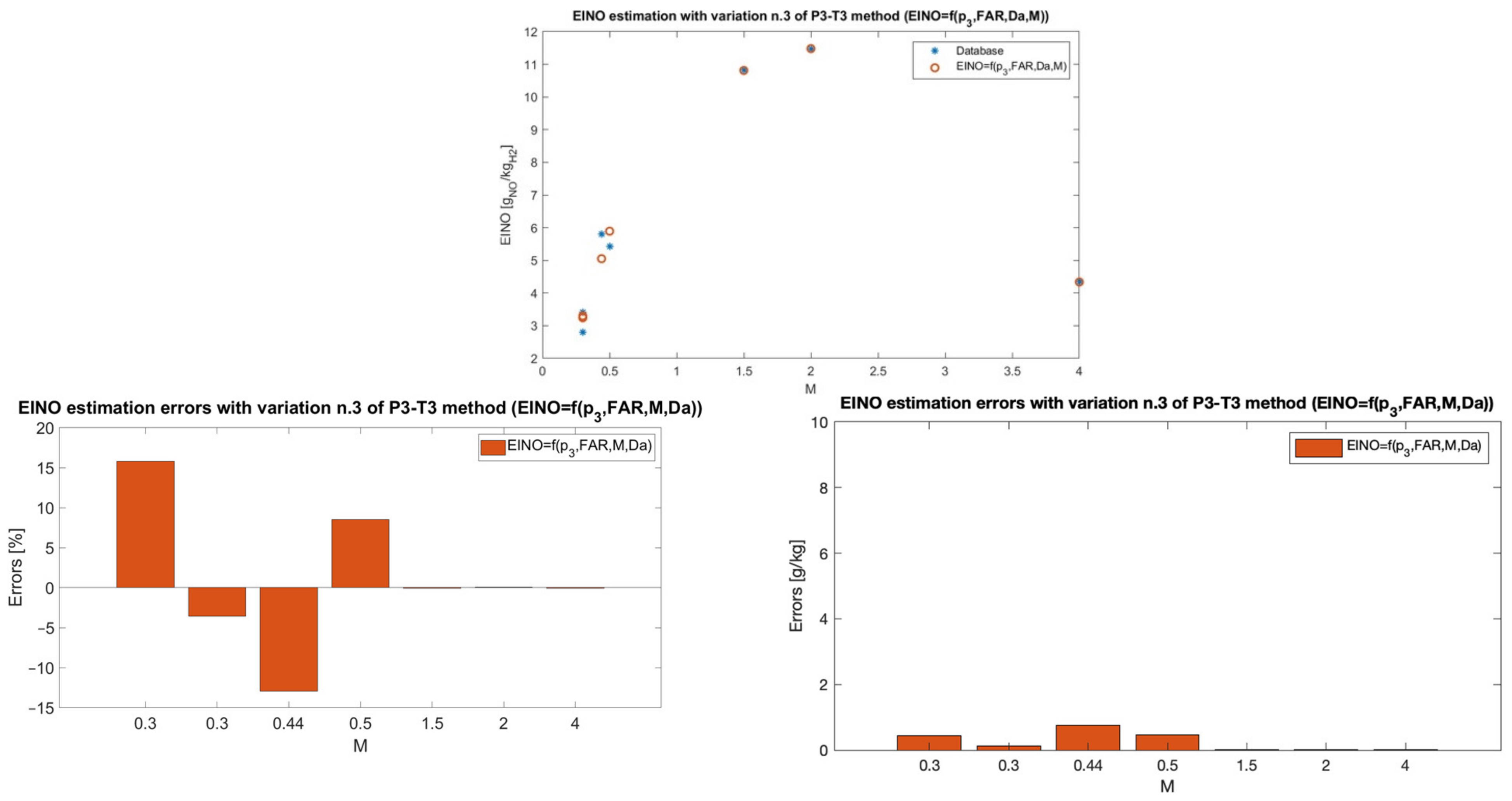
The Damköhler number is also responsible for a positive impact on EINO levels, meaning the NOx emissions increase as a consequence of the enhancement of the Damköhler number, which generally occurs through an increase in residence time, since the ignition delay is determined based on the chemical composition of the mixture. This parameter is included to account for the matching between the residence and ignition times, which have a strong influence on the formation of NOx in supersonic and hypersonic engines. As a matter of fact, a higher τ r e s causes a temperature rise in the combustor resulting in an increase in EINO; thus, a value of Da approaching unity is desirable for NOx minimization purposes.
Finally, Figure 14 compares the predictions coming from the various formulations showing the incremental reduction in error with respect to the original method. As can be observed from Figure 14, the addition of the Mach number and Damköhler number to the original formulation of the P3-T3 method significantly improves the prediction capability of this method and it is useful in its adaptation to a new propulsive system and propellant.

6. Conclusions

With the aim to avoid jeopardizing the dream of a new generation of high-speed aircraft fueled by hydrogen, and with the purpose of being ready to satisfy new future environmental requirements, this paper describes novel analytical formulations to estimate non-CO2 emissions at the beginning of the design process. In particular, to anticipate the nitrogen oxides emissions estimation in conceptual design, the authors developed the hydrogen and high-speed P3-T3 method (H2-P3T3), an evolution of the widely used P3-T3 method, properly conceived to support (i) innovative air-breathing propulsive systems for supersonic and hypersonic flights and (ii) greener fuels, such as hydrogen. This paper describes the step-by-step approach used to derive the innovative analytical formulations customized for an air turbo-rocket engine, revealing the existing correlation of nitrogen oxides production with the fuel-to-air ratio (FAR), the Mach number, and the Damköhler number (Da), which is a nondimensional variable directly related to hydrogen/air combustion, as it considers the matching between the residence time and the ignition delay times.
The most relevant achievements can be summarized as follows:
  • For the first time, a comprehensive review of emissions estimation techniques and their applicability beyond traditional subsonic aeroengines and fuels is reported in a scientific publication, providing the readers with useful and practical guidelines for the selection of the most appropriate technique for predicting emissions.
  • The paper exploits a unique dataset, which includes the propulsive and emissive database of the ATR covering very different operating conditions, from takeoff up to a wide range of cruise Mach numbers ranging from 0.3 to 4.
  • The novel H2-P3T3 method follows an approach similar to the original P3-T3 method, which allows the prediction of in-flight emissions knowing the emissions at sea-level conditions and the ratios of the flight-level and sea-level conditions of the pressure and fuel-to-air ratio at the inlet of the combustion chamber. However, the introduction of new parameters (i.e., Da) in the analytical formulations produces a modification of the original method, requiring the definition of additional sea-level trends for additional variables, including the ignition delay time and the residence time.
  • The original P3-T3 method presents a single analytical formulation with tuneable parameters to effectively represent different engine architectures. The new H2-P3T3 method encompasses three different formulations for the same engine architecture (ATR). The different formulations provide an increasing level of accuracy in the predictions, thus allowing a more flexible application throughout the design process.
  • The introduction of new correlated factors to improve the analytical formulations is based on the analysis of the most effective NOx minimization strategies adopted for hydrogen combustion of high-speed aviation propulsive systems.
  • The most complete formulation reveals an important scientific finding: emissions of nitrogen oxides from a high-speed engine using hydrogen are well correlated to the Da number, thus they are strongly affected by the characteristic times of the combustion process.
The proposed methodology can be used as a baseline for the customization of the analytical formulations to better represent other engine architectures, which represents an already planned activity in the near-term. Finally, the developed analytical formulations can quantitatively support tradeoff analysis at system and subsystems level, providing technical bases for the selection of the most sustainable subsystem architecture [40].

Author Contributions

Conceptualization, N.V. and R.F.; methodology, N.V. and R.F.; software, V.B. and G.S.; resources, N.V.; data curation, G.S.; writing—original draft preparation, R.F. and N.V.; writing—review and editing, V.B. and G.S.; visualization, V.B. and R.F.; supervision, N.V. All authors have read and agreed to the published version of the manuscript.

Funding

This research has been carried out in the framework of the “MDO and Regulations for Low Boom and Environmentally Sustainable Supersonic Aviation” (MORE&LESS) project. This project received funding from the European Union’s Horizon 2020 research and innovation program under grant agreement No. 101006856. Moreover, this research exploits the heritage of the “Stratospheric Flying opportunities for high-speed propulsion concepts” (STRATOFLY) project. This project received funding from the European Union’s Horizon 2020 research and innovation program under grant agreement No. 769246.

Data Availability Statement

Data are contained within the article.

Conflicts of Interest

The authors declare no conflict of interest.

References

  1. Lai, Y.Y.; Christley, E.; Kulanovic, A.; Teng, C.C.; Björklund, A.; Nordensvärd, J.; Karakaya, E.; Urban, F. Analysing the opportunities and challenges for mitigating the climate impact of aviation: A narrative review. Renew. Sustain. Energy Rev. 2022, 156, 111972, ISSN 1364-0321. [Google Scholar] [CrossRef]
  2. Grewe, V.; Gangoli Rao, A.; Grönstedt, T.; Xisto, C.; Linke, F.; Melkert, J.; Middel, J.; Ohlenforst, B.; Blakey, S.; Christie, S.; et al. Evaluating the climate impact of aviation emission scenarios towards the Paris agreement including COVID-19 effects. Nat. Commun. 2021, 12, 3841. [Google Scholar] [CrossRef]
  3. Intergovernmental Panel on Climate Change (IPCC) (Ed.) Climate Change 2022—Mitigation of Climate Change: Working Group III Contribution to the Sixth Assessment Report of the Intergovernmental Panel on Climate Change; Cambridge University Press: Cambridge, UK, 2023. [Google Scholar] [CrossRef]
  4. Thomson, R.; Weichenhain, U.; Sachdeva, N.; Kaufmann, M. Hydrogen|A Future Fuel for Aviation? Roland Berger Study; Roland Berger GMBH: Munich, Germany, 2020. [Google Scholar]
  5. EUROCONTROL. EUROCONTROL Forecast Update 2022–2024. 2022. Available online: https://www.eurocontrol.int/publication/eurocontrol-forecast-update-2022-2024 (accessed on 10 October 2022).
  6. Ram, M.; Bogdanov, D.; Aghahosseini, A.; Khalili, S.; Child, M.; Fasihi, M.; Traber, T.; Breyer, C. European Energy System Based on 100% Renewable Energy—Transport Sector. In Mobilität der Zukunft; ATZ/MTZ-Fachbuch; Siebenpfeiffer, W., Ed.; Springer Vieweg: Berlin/Heidelberg, Germany, 2021. [Google Scholar] [CrossRef]
  7. Chandrasekaran, N.; Guha, A. Study of Prediction Methods for NOx Emission from Turbofan Engines. J. Propuls. Power 2012, 28, 170–180. [Google Scholar] [CrossRef]
  8. Rizk, N.K.; Mongia, H.C. Semianalytical Correlations for NOx, CO and UHC emissions. Trans. ASME 1993, 115, 612–619. [Google Scholar] [CrossRef]
  9. ICAO. Annex 16 Volume II Aircraft Engine Emissions; ICAO: Montreal, QC, Canada, 2014.
  10. Silberhorn, D.; Dahlmann, K.; Görtz, A.; Linke, F.; Zanger, J.; Rauch, B.; Methling, T.; Janzer, C.; Hartmann, J. Climate impact reduction potentials of synthetic kerosene and green hydrogen powered mid-range aircraft concepts. Appl. Sci. 2022, 12, 5950. [Google Scholar] [CrossRef]
  11. DuBois, D.; Paynter, G.C. ‘Fuel Flow Method2’ for Estimating Aircraft Emissions. SAE Trans. 2006, 115, 1–14. Available online: https://www.jstor.org/stable/44657657 (accessed on 21 September 2023).
  12. Dinc, A. NOx emissions of turbofan powered unmanned aerial vehicle for complete flight cycle. Chin. J. Aeronaut. 2020, 33, 1683–1691, ISSN 1000-9361. [Google Scholar] [CrossRef]
  13. Wang, Y.; Yin, H.; Zhang, S.; Yu, X. Multi-objective optimization of aircraft design for emission and cost reductions. Chin. J. Aeronaut. 2014, 27, 52–58, ISSN 1000-9361. [Google Scholar] [CrossRef]
  14. Fusaro, R.; Viola, N.; Galassini, D. Sustainable Supersonic Fuel Flow Method: An Evolution of the Boeing Fuel Flow Method for Supersonic Aircraft Using Sustainable Aviation Fuels. Aerospace 2021, 8, 331. [Google Scholar] [CrossRef]
  15. Viola, N.; Fusaro, R.; Saracoglu, B.; Schram, C.; Grewe, V.; Martinez, J.; Marini, M.; Hernandez, S.; Lammers, K.; Vincent, A.; et al. Main Challenges and Goals of the H2020 STRATOFLY Project. Aerotec. Missili Spaz. 2021, 100, 95–110. [Google Scholar] [CrossRef]
  16. Viola, N.; Fusaro, R.; Ferretto, D.; Gori, O.; Saracoglu, B.; Ispir, A.C.; Schram, C.; Grewe, V.; Plezer, J.F.; Martinez, J.; et al. H2020 STRATOFLY project: FROM Europe to Australia in less than 3 hours. In Proceedings of the 32nd Congress of the International Council of the Aeronautical Sciences, ICAS 2021, Shanghai, China, 6–10 September 2021. [Google Scholar]
  17. Viola, N.; Fusaro, R.; Gori, O.; Marini, M.; Roncioni, P.; Saccone, G.; Saracoglu, B.; Ispir, A.C.; Fureby, C.; Nilsson, T.; et al. Stratofly mr3—How to reduce the environmental impact of high-speed transportation. In Proceedings of the AIAA Scitech 2021 Forum, Virtual, 11–15 and 19–21 January 2021; pp. 1–21. [Google Scholar]
  18. Steelant, J.; Varvill, R.; Walton, C.; Defoort, S.; Hannemann, K.; Marini, M. Achievements Obtained for Sustained Hypersonic Flight within the LAPCAT-II project. In Proceedings of the 20th AIAA International Space Planes and Hypersonic Systems and Technologies Conference, Glasgow, UK, 6–9 July 2015. [Google Scholar]
  19. Villace, V.F.; Steelant, J. The Thermal Paradox of Hypersonic Cruisers. In Proceedings of the 20th AIAA International Space Planes and Hypersonic Systems and Technologies Conference, Glasgow, UK, 6–9 July 2015; p. 14. [Google Scholar]
  20. Langener, T.; Erb, S.; Steelant, J. Trajectory Simulation and Optimization of the LAPCAT MR2 Hypersonic Cruiser Concept. In Proceedings of the 29th Congress of the International Council of the Aeronautical Sciences, St. Petersburg, Russia, 7–12 September 2014. [Google Scholar]
  21. Saccone, G.; Ispir, A.C.; Saracoglu, B.H.; Cutrone, L.; Marini, M. Computational evaluations of emissions indexes released by the STRATOFLY air-breathing combined propulsive system. Aircr. Eng. Aerosp. Technol. 2022, 94, 1499–1507. [Google Scholar] [CrossRef]
  22. Ispir, A.C.; Gonçalves, P.; Kurban, E.; Saracoglu, B.H. Thermodynamic efficiency analysis and investigation of exergetic effectiveness of stratofly mr3 aircraft propulsion plant. In Proceedings of the AIAA Scitech 2020 Forum, Orlando, FL, USA, 6–10 January 2020. [Google Scholar] [CrossRef]
  23. Nista, L.; Saracoglu, B.H. Numerical investigation of the STRATOFLY MR3 propulsive nozzle during supersonic to hypersonic transition. In Proceedings of the AIAA Propulsion and Energy Forum and Exposition, Indianapolis, IN, USA, 19–22 August 2019. [Google Scholar] [CrossRef]
  24. Ozden, A.; Nista, L.; Saracoglu, B.H. Performance evaluations of the stratofly mr3 propulsive nozzle at supersonic speeds. In Proceedings of the AIAA Propulsion and Energy 2020 Forum, Virtual, 24–28 August 2020; pp. 1–14. [Google Scholar] [CrossRef]
  25. Ferretto, D.; Fusaro, R.; Viola, N. Propellant subsystem design for hypersonic cruiser exploiting liquid hydrogen. In Proceedings of the AIAA AVIATION 2022 Forum, Chicago, IL, USA, 27 June–1 July 2022. [Google Scholar] [CrossRef]
  26. Viola, N.; Roncioni, P.; Gori, O.; Fusaro, R. Aerodynamic characterization of hypersonic transportation systems and its impact on mission analysis. Energies 2021, 14, 3580. [Google Scholar] [CrossRef]
  27. Roncioni, P.; Cutrone, L.; Marini, M. Aeropropulsive characterization of the hypersonic cruiser vehicle in stratofly project. In Proceedings of the 33rd Congress of the International Council of the Aeronautical Sciences, ICAS 2022, Stockholm, Sweden, 4–9 September 2022; Volume 6, pp. 4564–4575. [Google Scholar]
  28. Ferretto, D.; Gori, O.; Fusaro, R.; Viola, N. Integrated Flight Control System Characterization Approach for Civil High-Speed Vehicles in Conceptual Design. Aerospace 2023, 10, 495. [Google Scholar] [CrossRef]
  29. Rodríguez-Segade, M.; Hernández, S.; Díaz, J. Multi-bubble scheme and structural analysis of a hypersonic stratospheric flight vehicle. Aerosp. Sci. Technol. 2022, 124, 107514. [Google Scholar] [CrossRef]
  30. Rodríguez-Segade, M.; Hernández, S.; Amenedo, D.; Díaz, J. An Application of single and multi-objective optimization to the design of the hypersonic STRATOFLY-MR3 vehicle. In Proceedings of the AIAA Aviation and Aeronautics Forum and Exposition, AIAA AVIATION Forum 2021, Virtual, 2–6 August 2021. [Google Scholar] [CrossRef]
  31. Fernández-Villacé, V.; Paniagua, G.; Steelant, J. Installed performance evaluation of an air turbo-rocket expander engine. Aerosp. Sci. Technol. 2014, 35, 63–79, ISSN 1270-9638. [Google Scholar] [CrossRef]
  32. Goodwin, D.; Moffat, H.K.; Speth, R.L. Cantera: An Object-oriented Software Toolkit for Chemical Kinetics, Thermodynamics, and Transport Processes, (Version 2.6). 2023. Available online: http://www.cantera.org (accessed on 20 September 2023).
  33. Piscitelli, F.; Cutrone, L.; Pezzella, G.; Roncioni, P.; Marini, M. Nose-to-tail analysis of an air-breathing hypersonic vehicle using an in-house simplified tool. Acta Astronaut. 2017, 136, 148–158. [Google Scholar] [CrossRef]
  34. Tang, Y.; Kim, J.; Sforzo, B.; Scarcelli, R.; Raman, V. Numerical and Experimental Study of an Aircraft Igniter Plasma Jet Discharge. J. Propuls. Power 2023, 1–16. [Google Scholar] [CrossRef]
  35. Zettervall, N.; Fureby, C. Computational Study of Ramjet, Scramjet and Dual Mode Ramjet/Scramjet Combustion in a Combustor with a Cavity Flameholder. In Proceedings of the AIAA Aerospace Science, Kissimmee, FL, USA, 8–12 January 2018. [Google Scholar] [CrossRef]
  36. Saccone, G.; Natale, P.; Cutrone, L.; Marini, M. Hydrogen/Air Supersonic Combustion Modelling and Validation for Scramjet Applications. J. Fluid Flow Heat Mass Transf. (JFFHMT) 2022, 9, 136–147. [Google Scholar] [CrossRef]
  37. Ingenito, A. NOx reduction strategies in scramjet combustion. Aerosp. Sci. Technol. 2016, 59, 189–198. [Google Scholar] [CrossRef]
  38. Pouech, P.; Duchaine, F.; Poinsot, T. Premixed flame ignition in high-speed flows over a backward facing Step. Combust. Flame 2021, 229, 111398. [Google Scholar] [CrossRef]
  39. Fedorov, A.V.; Fedorova, N.N.; Vankova, O.S.; Tropin, D.A. Verification of kinetic schemes of hydrogen ignition and combustion in air. AIP Conf. Proc. 2018, 1939, 020019. [Google Scholar] [CrossRef]
  40. Chiesa, S.; Farfaglia, S.; Fioriti, M.; Viola, N. Design of all electric secondary power system for future advanced medium altitude long endurance unmanned aerial vehicles. Proc. Inst. Mech. Eng. Part G J. Aerosp. Eng. 2012, 226, 1255–1270. [Google Scholar] [CrossRef]
Figure 1. GHG emissions from transport in the EU, by transport mode and scenario [5].
Aerospace 10 00909 g001
Figure 2. Percentual impact of aviation on the transport sector in the EU [6].
Aerospace 10 00909 g002
Figure 3. Hydrogen–air explosivity diagram with the original ATR operating points from propulsive database, with spontaneous combustion.
Aerospace 10 00909 g003
Figure 4. Hydrogen–air explosivity diagram with the ATR operating points reassessed after thermal ignition strategy.
Aerospace 10 00909 g004
Figure 5. Hydrogen–air explosivity diagram with the ATR operating points reassessed after chemical ignition strategy.
Aerospace 10 00909 g005
Figure 6. Summary view of the logics behind the definition of the new formulations of the H2-P3T3 methodology.
Aerospace 10 00909 g006
Figure 7. Derivation of trends for estimating sea-level conditions.
Aerospace 10 00909 g007
Figure 8. Comparison of EINO predictions with the original formulation and emission estimations from 0D chemical-kinetic simulations (top) and related relative and absolute errors (bottom).
Aerospace 10 00909 g008
Figure 9. Adiabatic flame temperature correlation to equivalence ratio for different fuels.
Aerospace 10 00909 g009
Figure 10. Comparison of EINO predictions with the new formulation in Equation (8) and emission estimations from 0D chemical-kinetic simulations (top) and related relative and absolute errors (bottom).
Aerospace 10 00909 g010
Figure 11. Comparison of EINO predictions with the new formulation in Equation (9) and emission estimations from 0D chemical-kinetic simulations (top) and related relative and absolute errors (bottom).
Aerospace 10 00909 g011
Figure 12. Derivation of trends for sea-level conditions estimation for residence time and ignition delay time.
Aerospace 10 00909 g012
Figure 13. Comparison of EINO predictions with the new formulation in Equation (16) and emission estimations from 0D chemical-kinetic simulations (top) and related relative and absolute errors (bottom).
Aerospace 10 00909 g013
Figure 14. Comparison of EINO predictions with the new formulation in Equation (16) and emission estimations from 0D chemical-kinetic simulations (top) and related relative and absolute errors (bottom).
Aerospace 10 00909 g014
Table 1. ATR sea-level conditions.
From Propulsive Database From Emissive Database
MZ
(m)
mfuel
(kg/s)
mair
(kg/s)
FARphiT3,air
(K)
T3,fuel
(K)
T3,mix
(K)
p3
(Pa)
HEINO
(gNO/kgH2)
0.308.88401.410.0220.759363542406.01190,000−0.03072.12
0.35010.09463.830.0220.759393583438.66265,000−0.03071.84
0.44013.63588.740.0230.793390441402.67240,000−0.03072.37
0.5014.41662.620.0220.759380377379.28232,000−0.03071.4
Table 2. ATR flight-level operating points.
From Propulsive Database From Emissive Database
MZ
(m)
mfuel
(kg/s)
mair
(kg/s)
FARphiT3,air
(K)
T3,fuel
(K)
T3,mix
(K)
p3
(Pa)
HEINO
(gNO/kgH2)
0.34008.88384.490.0230.793366529406.51190,000−0.01332.8
0.38008.88368.130.0240.828368517406.22190,0000.00253.42
0.44200013.65472.780.0291.000402374393.76240,0000.04115.8
0.5250014.35507.760.0280.966410340389.91251,0000.05385.43
0.7580006.62390.100.0170.586355510385.44120,0000.11547.19
0.8289217.06306.330.0230.793363444383.13112,0000.1172.76
1.5161346.61231.640.0291.000469426456.35120,0000.11910.82
2174118.53271.100.0311.069550396502.52149,0000.11911.47
4241522.68177.650.0150.5179381019952.37343,0000.11824.34
Table 3. Additional ATR sea-level conditions: residence time and ignition delay time.
Machτres [s] τign,OH [s] Da
0.36.442 × 10−12.235 × 10−228.83
0.357.200 × 10−12.642 × 10−227.25
0.445.534 × 10−12.782 × 10−219.89
0.55.103 × 10−12.970 × 10−217.18
Table 4. Additional ATR flight-level operating points: residence time and ignition delay time.
Machτres (s) τign,OH (s) Da
0.36.640 × 10−12.226 × 10−229.83
0.36.862 × 10−12.225 × 10−230.85
0.446.627 × 10−12.854 × 10−223.22
0.56.556 × 10−13.018 × 10−221.72
0.754.669 × 10−11.601 × 10−229.16
0.825.214 × 10−11.501 × 10−234.73
1.55.854 × 10−11.196 × 10−248.96
25.476 × 10−11.224 × 10−244.73
41.213 × 101.457 × 10−3832.41
Table 5. A summary of the formulations for an ATR engine inside the H2-P3T3 method.
abcdf
Original formulation10.4---
E I N O x F L = f ( P 3 ,   F A R ) 1−0.36143.8132--
E I N O x F L = f ( P 3 ,   F A R ,   M ) 1.59960.31873.50.3143-
E I N O x F L = f P 3 ,   F A R ,   M ,   D a 1.81100.22732.42760.32990.7742
Disclaimer/Publisher’s Note: The statements, opinions and data contained in all publications are solely those of the individual author(s) and contributor(s) and not of MDPI and/or the editor(s). MDPI and/or the editor(s) disclaim responsibility for any injury to people or property resulting from any ideas, methods, instructions or products referred to in the content.

