Article

An Analysis of the Vibration Characteristics of an Aviation Hydraulic Pipeline with a Clamp

1
College of Aeronautical Engineering, Civil Aviation University of China, Tianjin 300300, China
2
Tianjin Bool Technology Co., Ltd., Tianjin 300392, China
*
Author to whom correspondence should be addressed.
Aerospace 2023, 10(10), 900; https://doi.org/10.3390/aerospace10100900
Submission received: 19 September 2023 / Revised: 16 October 2023 / Accepted: 17 October 2023 / Published: 22 October 2023
(This article belongs to the Special Issue State Monitoring and Health Management of Complex Equipment)

Abstract

:
Taking an aviation hydraulic pipeline as the research object, a fluid–solid coupling vibration model of the pipeline system, considering the influence of the clamp, is established. The clamp is equivalent to the combined form of the constraint point and the pipeline. The equivalent stiffness of the clamp in each direction is obtained via the finite element method and substituted into the vibration model. The vibration response of the hydraulic pipeline system is obtained by changing the boundary conditions. The validity and accuracy of the vibration model were verified via the finite element method. The results show that the maximum error of the natural frequency of the pipeline system is within the acceptable range, which can prove that the model can better simulate the dynamic characteristics of the pipeline system and has a certain engineering reference value for the vibration analysis of hydraulic pipelines in aviation.

1. Introduction

The modern aviation hydraulic system is gradually developing in the direction of a high pressure, high speed, and high power [1,2], which greatly improves the working efficiency of the hydraulic system, but also causes a strong vibration of the hydraulic pipeline. Because of the existence of a hydraulic pump in the hydraulic system and the connection between the hydraulic pipeline and the structure, the hydraulic pipeline will be stimulated by the pulsating excitation from the pump source and the resulting foundation of the structure [3]. In addition, the pulsating excitation of the fluid in the pipeline will also cause the fluid–solid coupling of the hydraulic pipeline, making the vibration characteristics of the pipeline more complicated.
The vibration characteristics of the pipeline system have important scientific research and engineering application value [4]. On the one hand, the hydraulic pipeline will be subjected to external excitation such as pulsation excitation from the pump, and on the other hand, it will be subjected to fluid excitation from the inside of the pipeline. Nowadays, there are many studies on the influence of power units on the vibration characteristics of hydraulic devices: Michał Stosiak et al. [3] discuss minimizing the effect of the external mechanical vibration on hydraulic valves in different military hydraulic drive systems. They noted the effect of the changes in the pressure pulsation spectrum of a hydraulic system with a vibrating directional control valve. In this paper, the problem of vibration excitation of the directional control valve spool is noted, and the effect of this vibration—changes in the pressure pulsation spectrum of a hydraulic system with a vibrating directional control valve—is indicated. The complex coupling vibration between the fluid and the pipeline will be caused by the fluid flow state, because the pipeline system is subjected to a high-strength fluid pressure. The fluid–solid coupling vibration of an aviation hydraulic pipeline is easily caused by its structure, support point, and external excitation. Therefore, when calculating the dynamic characteristics of a pipeline system, considering the vibration characteristics of the internal medium, i.e., the fluid–solid coupling vibration characteristics, has become a hot issue. For this reason, researchers have carried out a lot of work. Wu et al. [5] focused on the self-excited vibration under the interaction between the pipeline structure and fluid by using the dynamic mesh technique and the transient fluid–solid coupling method of large eddy simulation and verified it with experimental results. Considering the coupling between fluids and pipelines, Duan et al. [6] studied the effect of isodynamic loads on pipelines under high temperatures and pressure, and compared and analyzed the natural frequencies of pipelines under a dry mode and a wet mode. Gao et al. [7] proposed an improved model reduction method and proved that this method is beneficial to solving the vibration characteristics of long-distance hydraulic pipelines with multi-point support by comparing and analyzing the calculation methods of the whole model and the simplified model. Xu et al. [8] studied the fluid–solid coupling vibration characteristics of branch pipes under different supporting conditions and boundary conditions, and used the fourteen-equation model and the transfer matrix method to establish and solve the dynamic model. Sadeghi and Karimi-Dona [9] studied the dynamic behavior of pipelines under the action of moving mass moments, considering the influence of rotational inertia, large displacement, and asymmetric damping caused by the Coriolis effect. When studying the axial vibration response characteristics of the fluid–solid coupling vibration of hydraulic pipelines, Quan et al. [10] modified the fluid shear-friction stress model in the model by combining the Zielke model and the Brunone model, and finally, the validity of the model was verified by experiments. Li et al. [11] established the wet modal vibration equation of a pipeline, including fluid mass, pressure, flow rate, stiffness, and damping, and focused on the influence of fluid factors on the vibration characteristics of the pipeline. Quan et al. [12] explored the influence of the bending parameters of a curved pipeline on the frequency domain response of the pipeline system by establishing a fourteen-equation model of the fluid–solid coupling of the pipeline. Based on the improved Fourier series method, Ma et al. [13] established a fluid–solid coupling vibration characteristic model of a pipeline system under arbitrary elastic support and verified and solved it under complex constraints.
The study of hydraulic devices mainly focuses on power units (pumps, cylinders, etc.), without considering the connecting components. Karpenko M et al. [14] proposed a research analysis of high-pressure hoses and junctions during technical maintenance. The main issue in high-pressure hoses with repair fitting connections is changes in the size and configuration of the cross-section area of the flow stream inside the hydraulic line. As a result, it is necessary to figure out the behavior of the fluid inside the hose and the effect of interface changes on energy consumption, since the sudden change in the hose cross-section will affect the pressure and energy parameters of the hydraulic system. Therefore, Karpenko M et al. analyzed the fluid behavior and energy efficiency of high-pressure hoses by numerical simulation based on Navier–Stokes equations and experimental measurements of fluid flow pressure in high-pressure hoses. They found that a nonrepaired hose performed in the most efficient way compared with a repaired hose, because the change in the cross-section area of the repaired hose was greater than that of the unrepaired hose, and the difference in the change in the cross-section area would have a significant impact on the flow characteristics. As a connecting component, the clamp also has an important influence on the calculation of the vibration characteristics of the pipeline system. Considering the influence of clamps, Liu et al. [15] proposed a novel frequency response function (FRF)-based method for the exact calculation of the mode shapes, and based on this, they combined the spectral analysis method (SAM) and the transfer matrix method (TMM) to solve the natural frequency and transient response of cascaded pipelines. Lin et al. [16] focused on the nonlinear vibration characteristics of the clamp–pipeline system caused by the looseness of the clamp. In their research process, according to the real data obtained from the test, the clamp is simplified as a nonlinear spring damper, and the nonlinear model of the pipe with a clamp is established. Finally, the analytical solution of the model is obtained by using a multi-scale method. Gao and Sun [17] obtained the support stiffness and damping of the hoop using the hammering test and inversion method and analyzed the influence of the preload on the support stiffness and damping of the pipeline hoop. Gao et al. [18] proposed a method based on the measured frequency response function (FRF) to invert the support stiffness and damping of the clamp in the pipeline system, but the damping obtained through this method is too dependent on the natural frequency, and the error is slightly large. Li et al. [19] obtained the equivalent stiffness of the clamp through an experimental method. Based on the results, they studied the influence of the pipe diameter and temperature on the stiffness.
However, in the previous theoretical research on the vibration characteristics of a pipeline system, researchers often simplify the clamp as a concentrated mass point when modeling the pipeline system. This simplification ignores the influence of the clamp factor. In this paper, the influences of clamps are considered when calculating the vibration characteristics of aviation pipelines. The clamps in the pipeline system are equivalent to the combination of constraint points and pipelines. A mathematical model including clamp stiffness is established. At the same time, based on the previous research results [20], this paper proposes a method for obtaining the equivalent stiffness of clamps via the finite element method. Finally, the above contents are integrated into the calculation model of the vibration characteristics of the pipeline system, and the overall vibration characteristics of the pipeline system are obtained.

2. Fluid–Solid Coupling Model

It is important to establish an accurate and efficient hydraulic pipeline vibration model for the analysis of hydraulic pipeline vibration characteristics. The fluid–solid coupling 14-equation model is widely used to solve the vibration problem of pipeline systems. Based on the 14-equation model of fluid–solid coupling and referring to relevant research [21,22], this chapter establishes the fluid–solid coupling vibration model of a hydraulic pipeline, including the axial vibration, radial vibration, and torsional vibration.

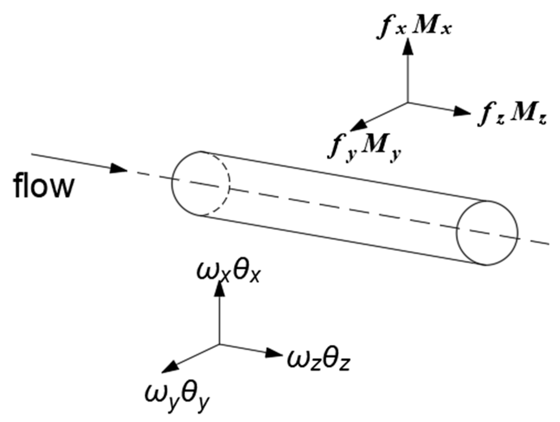
2.1. Fluid–Solid Coupling Fourteen-Equation Model

In this paper, based on the Timoshenko beam model, a 14-equation model of fluid–solid coupling, including fluid–solid interactions, the fluid pressure inside pipelines, the fluid velocity, gravity, the Coriolis force, the centrifugal force, and other factors, is established.
The fluid–solid coupling fourteen-equation model is established to describe the axial, radial, and torsional motion of the pipeline in three-dimensional space, and is used for the frequency domain solution. The schematic diagram of the pipeline force is shown in Figure 1. The equations are as follows:
(1)
Axial vibration equation:
V f t + V 0 V f z + 1 ρ f P z + g sin β = 0
w z t + f z z 1 ρ p A p + g sin β = 1 ρ p A p f e z
P t 2 v K w z + K V f z = 0
f z t + [ E A p + A p 4 v 2 K e R ( 2 + e R ) ] w z z = A p 2 v 2 K e R ( 2 + e R ) V f z
(2)
Radial vibration equation:
x-z plane:
M y t + E I p θ y z = 0
w x t + 1 m f x z + g cos β 1 m f e x = 2 m f V m w x z + m f V 2 + P A f m E I p M y
θ y t + 1 B M y z + 1 B f x = M e y B
f x t + κ A p G w x z κ A p G θ y = 0
y-z plane:
M x t + E I p θ x z = 0
w y t + 1 m f y z + 2 m f V m w y z + m f V 2 + P A f m E I p M x + g cos β = 1 m f e y
f y t + κ A p G w y z + κ A p G θ x = 0
θ x t + 1 B M x z 1 B f y = M e x B
(3)
Torsional vibration equation:
M z t + G J p θ z = 0
θ z t + 1 ρ p J p M z z 1 ρ p J p M e z = 0
where m = m p + m f = ρ p A p + ρ f A f .
In the above formulas, the following abbreviations are used: V—velocity; P—pressure; e—thickness-to-diameter ratio of pipelines; A—cross-sectional area; w —linear displacement of pipeline; θ —pipeline rotating angle; f—force; M—moment; m—total mass of pipeline; I—flexure moment of inertia; J—polar moment of inertia; G—shear modulus; E—pipeline elastic modulus; K —elastic correction modulus; v—Poisson‘s ratio; κ —Shear coefficient; ρ —density; subscript f—fluid; subscript p—pipeline.
Convert the above equation expression into a matrix expression:
A y ( z , t ) t + B y ( z , t ) z + C y ( z , t ) + D = r _ ( z , t )
y z , t = V f   P f   w z   f z   M y   θ y   w x   f x   M x   θ x   w y   f y   θ z   M z T
where y ( z , t ) are 14 state vectors. A, B, C, and D are coefficient matrixes. According to the solution method of reference [21,23], the transfer matrix method is used to solve the model. Combined with the boundary conditions and the excitation matrix, the overall expression of the pipeline can be obtained as
Y ( L , s ) = U a l l ( L , s ) Y ( 0 , s )
where Y L , s is the end-state variable of the pipeline system. U a l l s = U n L N , s U i L i , s U 1 L 1 , s is the overall transfer matrix of the pipeline. Y 0 , s is the initial state variable of the pipeline. U i ( L i , s ) is the field matrix of each pipeline.

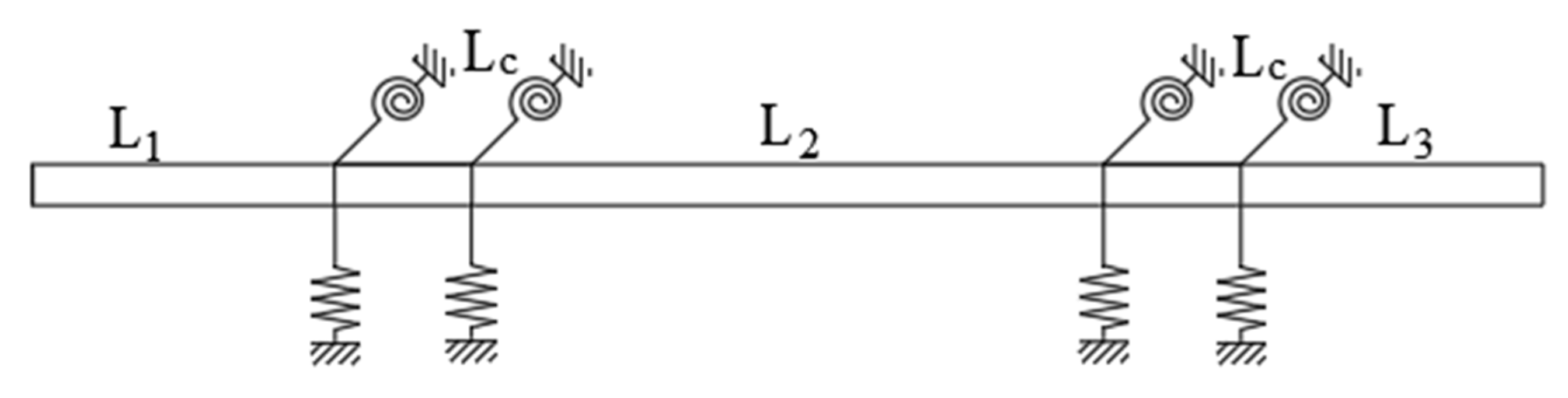
2.2. Establishment of the Intermediate Constraint Matrix of the Clamp

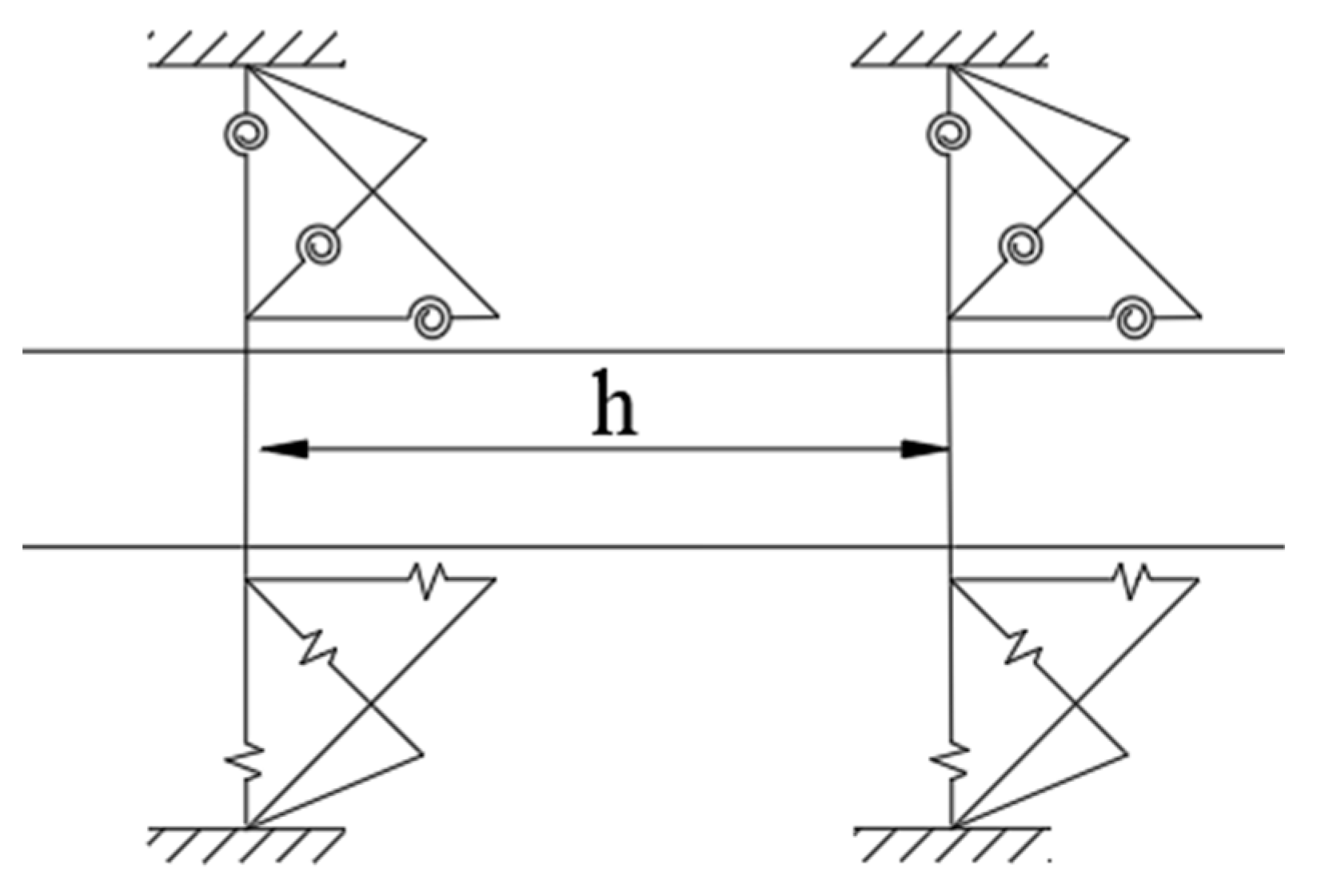
2.2.1. The Discrete Stiffness Model of Clamps

In the previous model establishment process, researchers have often simplified the clamp in the pipeline system as a concentrated mass point, as shown in Figure 2. This simplification process only considers the influence of the clamp mass but ignores the influence of the clamp stiffness on the vibration characteristics of the pipeline system. Therefore, this paper proposes a discretization model considering the equivalent stiffness and the width of the clamp. The concentrated mass point of the clamp is discretized into a combination of two constrained points and the pipeline, as shown in Figure 3. The distance between the two constraint points is the width of the clamp. The equivalent stiffness of each constraint point in the three directions of x, y, and z is k i / 2 (linear stiffness) and k i j / 2 (angular stiffness), i.e., the stiffness of the constraint point in the three directions of x, y, and z is half of the stiffness measured for the clamp in this direction.
The dynamic equilibrium equations, force equilibrium equations, and moment equilibrium equations of the variables on both sides before and after any constraint point are constructed, and then, frequency domain expressions are obtained after the Laplace transform. Specifically, the z-direction satisfies the following relationship:
L { V f } L = L { V f } R
L { P } L = L { P } R
L { ω z } L = L { ω z } R
L { f z } L L { f z } R = L { m c { ω z } t + k z ω z } = m c s L { ω z } R + k y s L { ω z } R
The z-x plane satisfies the following relationship:
L { M x } L L { M x } R = L { k z y { θ x } R t } = k z y s L { θ x } R
L { θ x } L = L { θ x } R
L { ω y } L = L { ω y } R
L { f y } L L { f y } R = L { m c { ω y } t + k y ω y } = m c s L { ω y } R + k y s L { ω y } R
The z-y plane satisfies the following relationship:
L { M y } L L { M y } R = L { k x z { θ y } R t } = k x z s L { θ y } R
L { θ y } L = L { θ y } R
L { ω x } L = L { ω x } R
{ f x } L { f x } R = L { m c { ω x } t + k x ω x } = m c s L { ω x } R + k x s L { ω x } R
The z-direction torsional motion satisfies the following relationship:
L{θz}L = L{θz}R
L { M z } L L { M z } R = L { k z y { θ z } R t } = k z y s L { θ z } R
In the above expression, L {   } represents the Laplace transform. k i is the linear stiffness in all directions. k i y is the angular stiffness in all directions. Subscripts L and R represent the left and right sides of the constraint points.
Convert the above expression into a matrix form:
U(R,s) = N(s)U(L,s)
where N(s) is the point transfer matrix for each constraint point.

2.2.2. Measurement of Clamp Stiffness

Taking a P-type clamp as an example, the stiffness solution and analysis verification are carried out. Combined with the stiffness calculation method for pipeline accessories in the relevant industry handbook [24], the equivalent stiffness of the clamp in each direction can be obtained according to the ratio of the load in each direction to the deformation in this direction.
The clamp is composed of an internal hoop and an external rubber gasket. The materials of the hoop and the rubber are 0Cr18Ni9 and EPDM, respectively. The material parameters and constitutive model parameters refer to the relevant literature [19,25], as shown in Table 1.
We built a three-dimensional model of the entity and meshed it, as shown in Figure 4, because the bolt has little effect on the stiffness of the clamp, and we only applied the fixed constraint at the screw hole to simulate the effect of the bolt.
In the process of analysis, it is assumed that there is no relative sliding between the clamp hoop and the external rubber of the clamp, and that the contact surface between the clamp inner ring rubber and the pipeline is related to the center point in the clamp ring. When the contact surface is displaced due to the force, the position of the center point will also change. The connection between the contact surface and the center point is a rigid connection. The advantage of this connection method is that it only considers the displacement of the whole clamp caused by an external force, so as to avoid the large deformation and displacement of the rubber surface under the action of external forces, while the band does not change significantly, thus affecting the accuracy of the calculation results.
In the calculation process, the force in the x, y, and z directions and the torque around the x, y, and z axes are applied to the contact surface of the clamp rubber and the pipeline, respectively, and the displacement and torsion angle of the center point in each direction are measured. The results are substituted into Formulas (33) and (34) to obtain the linear stiffness and angular stiffness in each direction, and the calculation results are shown in Figure 5 and Table 2.
k i = F i / i
k i j = M i j / i j

2.3. Excitation Matrix and Boundary Conditions

In the actual application environment, there are often more complex excitation conditions and boundary conditions in the pipeline system. In this paper, the excitation conditions (including the fluid excitation and mechanical excitation) and boundary conditions are established through the derivation process in Reference [22].
In the fourteen-equation model, there are seven boundary equations at both ends of the pipeline, including the constraint force in the three directions of x, y, and z, the constraint moment rotating around the three axes of x, y, and z, and the external excitation. Therefore, the excitation matrix at each end contains seven different external loads, as shown in Equations (35) and (36).
[ Q 0 ] 7 × 1 = [ V ( 0 , s ) , f e z ( 0 , s ) , f e x ( 0 , s ) , M e y ( 0 , s ) , f e y ( 0 , s ) , M e x ( 0 , s ) , M e z ( 0 , s ) ]
[ Q L ] 7 × 1 = [ V ( L , s ) , f e z ( L , s ) , f e x ( L , s ) , M e y ( L , s ) , f e y ( L , s ) , M e x ( L , s ) , M e z ( L , s ) ]
where the subscript 0 represents the initial end of the pipeline, and the subscript L represents the end of the pipeline.
In this excitation condition, the first excitation element of each excitation matrix is the fluid excitation, and the remaining elements are the force and moment equations on the corresponding three motion planes.
A boundary matrix containing elastic constraints and added mass is established, as shown in Equations (37) and (38).
D 0 ( s ) = 1 0 1 0 0 A f Z z ( 0 ) 1 0 0 Z y ( 0 ) 1 1 Y x ( 0 ) 0 0 0 0 Z x ( 0 ) 1 1 Y y ( 0 ) 0 0 Y z ( 0 ) 1
D L ( s ) = 1 0 1 0 0 A f Z z ( L ) 1 0 0 Z y ( L ) 1 1 Y x ( L ) 0 0 0 0 Z x ( L ) 1 1 Y y ( L ) 0 0 Y z ( L ) 1

3. Numerical Model Calculation

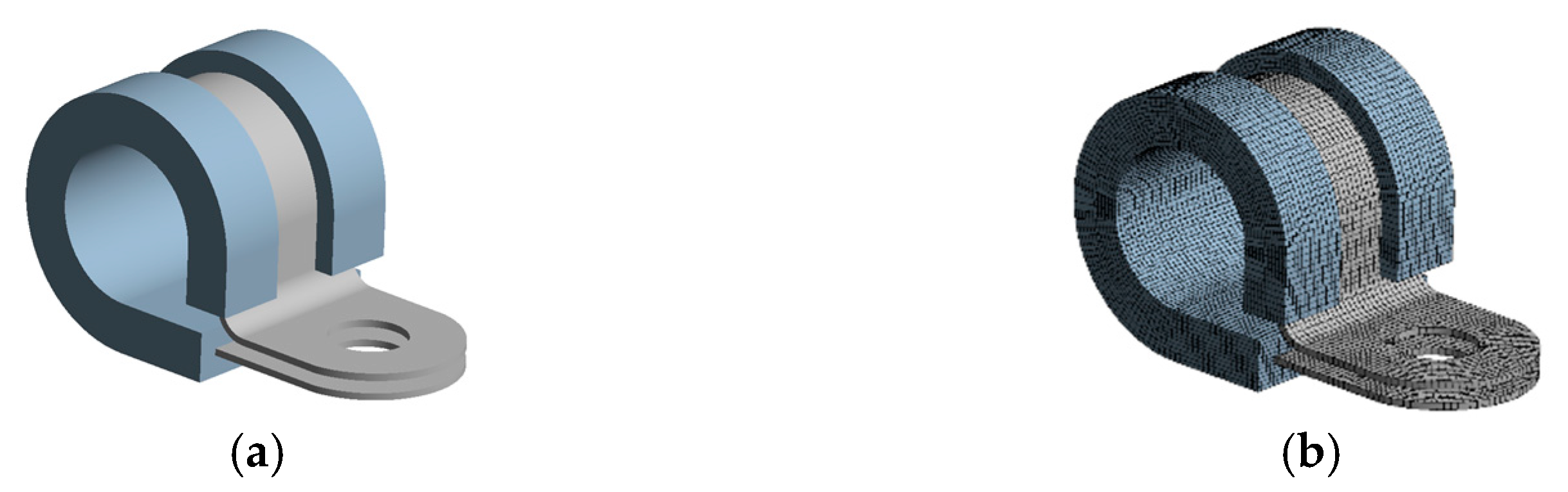
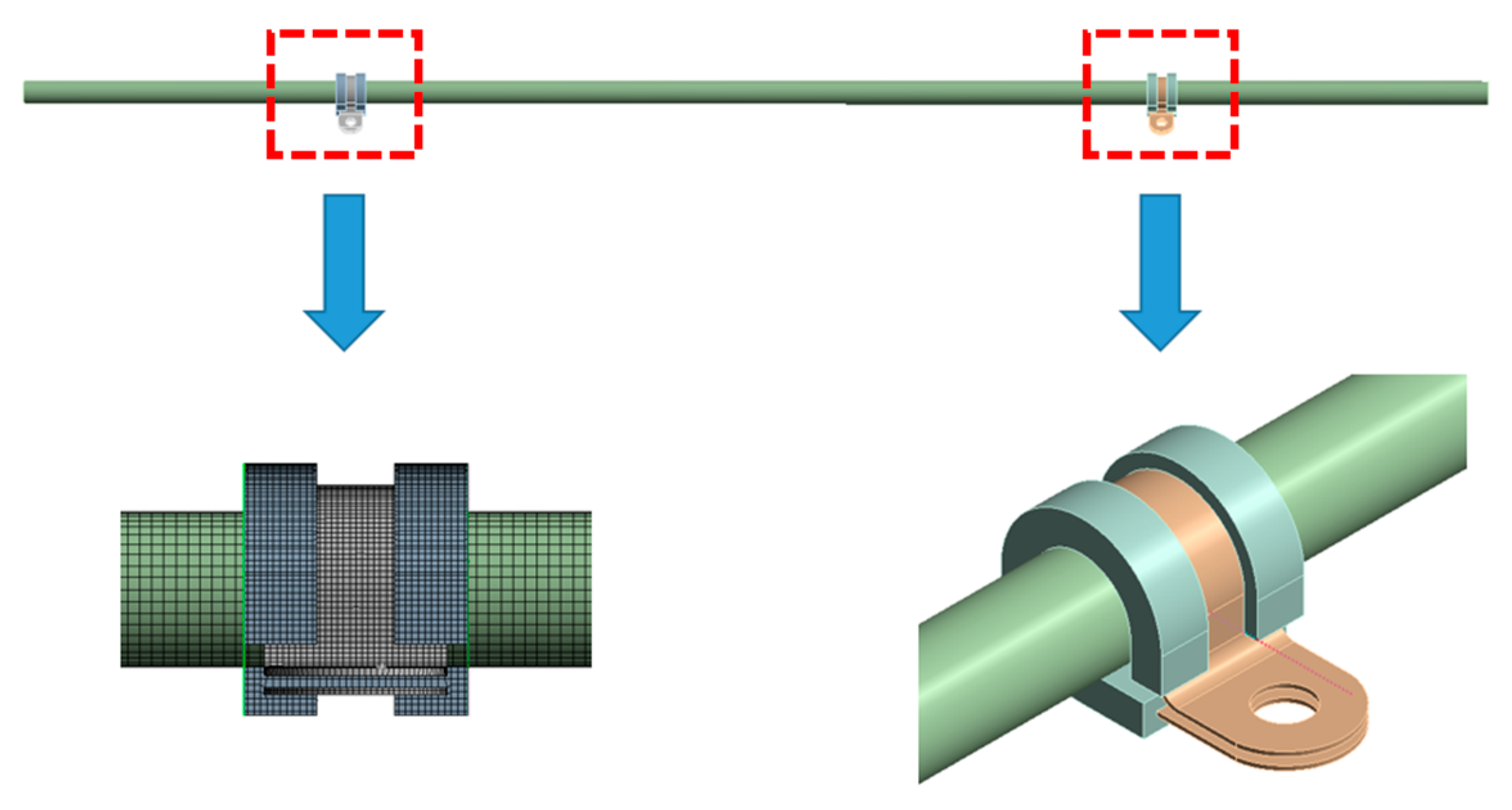
3.1. Establishment of a Model for a Hydraulic Pipeline for Aviation

In order to verify the accuracy and reliability of the method proposed in this paper, a section of aviation hydraulic pipelines is used for numerical solution and model verification. The pipeline is a straight pipe, and there is a clamp at both ends to realize the fixation of the pipeline, as shown in Figure 6. The relevant parameters of the pipeline are shown in Table 3.
Combined with the inference of the theoretical model, the overall transfer matrix expression of the above pipeline is shown in Equation (39).
Y ( L , s ) = U 5 ( L 3 , s ) N c 4 ( s ) U 4 ( L L c , s ) N c 3 ( s ) U 3 ( L 2 , s ) N c 2 ( s ) U 2 ( L L c , s ) N c 1 ( s ) U 1 ( L 1 , s ) Y ( 0 , s )
where U 5 L 3 , s U 3 L 2 , s U 1 L 1 , s is the field transfer matrix of the pipeline, N c 4 ( s ) N c 3 ( s ) N c 2 ( s ) N c 1 ( s ) is the point transfer matrix of the clamp constraint, and U 4 ( L L c , s ) U 2 ( L L c , s ) is the field transfer matrix of the equivalent clamp width.

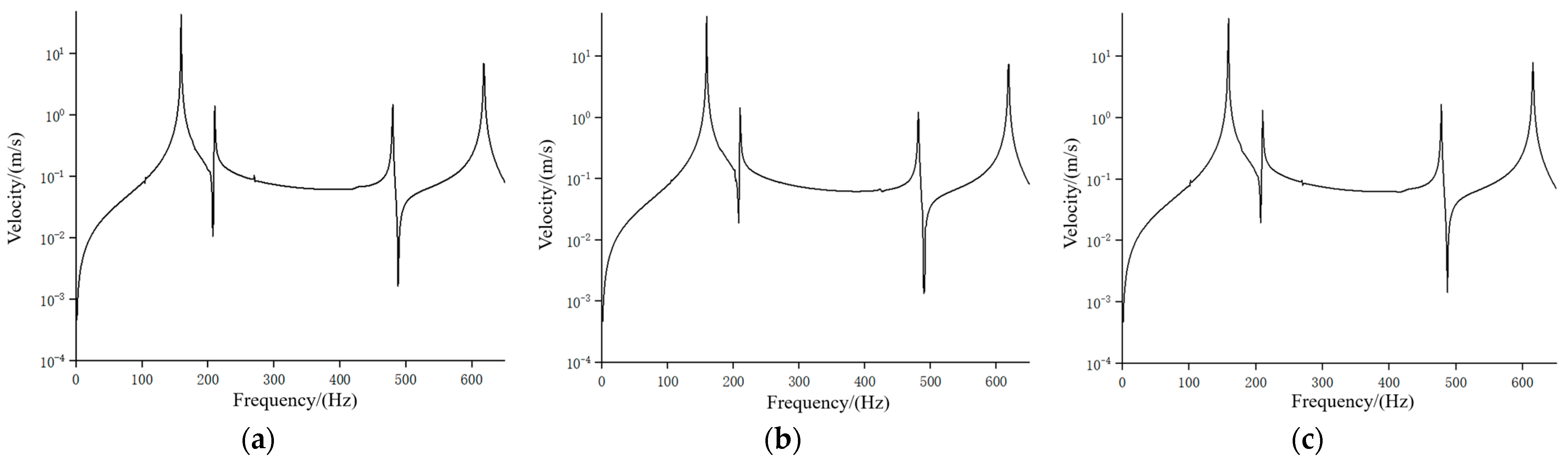
3.2. Vibration Characteristics Analysis of a Hydraulic Pipeline for Aviation

When analyzing the vibration characteristics of the hydraulic pipeline, it is assumed that the pipeline is filled with a flowing medium. In this paper, liquid water is used as the internal medium. The two ends of the pipeline are in a free state. The medium pressure changes periodically and serves as the excitation source of the pipeline, and the pressure change conforms to the simple harmonic pulsation excitation. The pressure pulsation information is shown in Table 4. Keeping the pressure of the medium unchanged, the axial vibration response characteristics of the pipeline system at different speeds are explored by changing the speed of the medium. The authors carried out multiple sets of calculations for V = 1, 2, 3, 4, and 5 m/s, and the actual results showed that the calculation results of different groups were almost the same. Therefore, in this paper, only the calculation results were V = 1, 3, and 5 m/s are selected for presentation, as shown in Figure 7.
It can be seen from the figure that the change in flow velocity in the pipeline system does not affect the natural frequency of the fluid–solid coupling vibration of the pipeline system. Compared with References [22,26], it can be seen that the result is within a reasonable range. The reason is that the increase in flow velocity enhances the fluid–solid coupling effect in the pipe, resulting in a stronger vibration response amplitude.

4. Model Verification and Analysis

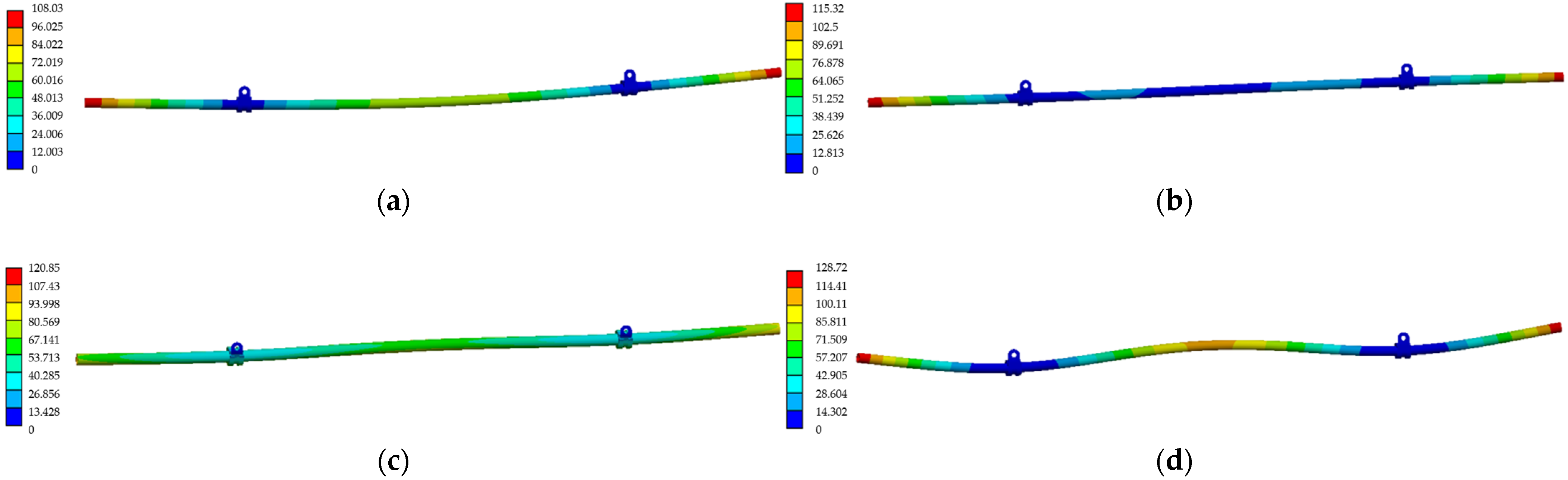
4.1. Finite Element Verification of the Model

In order to further verify the validity of the model, this paper uses a finite element simulation analysis to verify. According to the actual size of the pipe and clamp, the calculation model is established, and the grid is divided, as shown in Figure 8. In the analysis process, the friction contact is set between the clamp and the pipeline, and the inner ring of the clamp is bound to the external rubber, without considering its relative slip; a fixed constraint is applied at the bolt hole of the clamp. For the liquid-filled pipeline, the pressure changes on the inner wall of the pipeline should be obtained via fluid simulation. Because the internal medium of the pipeline is an ideal fluid, the fluid gravity is considered in the fluid simulation process, and the complex fluid state, such as the compressibility and viscosity of the fluid, is not considered. Then, the fluid simulation results are imported into the modal analysis as the boundary conditions to calculate the natural frequency of the hydraulic pipeline. Since the change in the pipeline speed has no effect on the change in the natural frequency of the pipeline system, this paper only verifies the numerical results at V = 3 m/s.

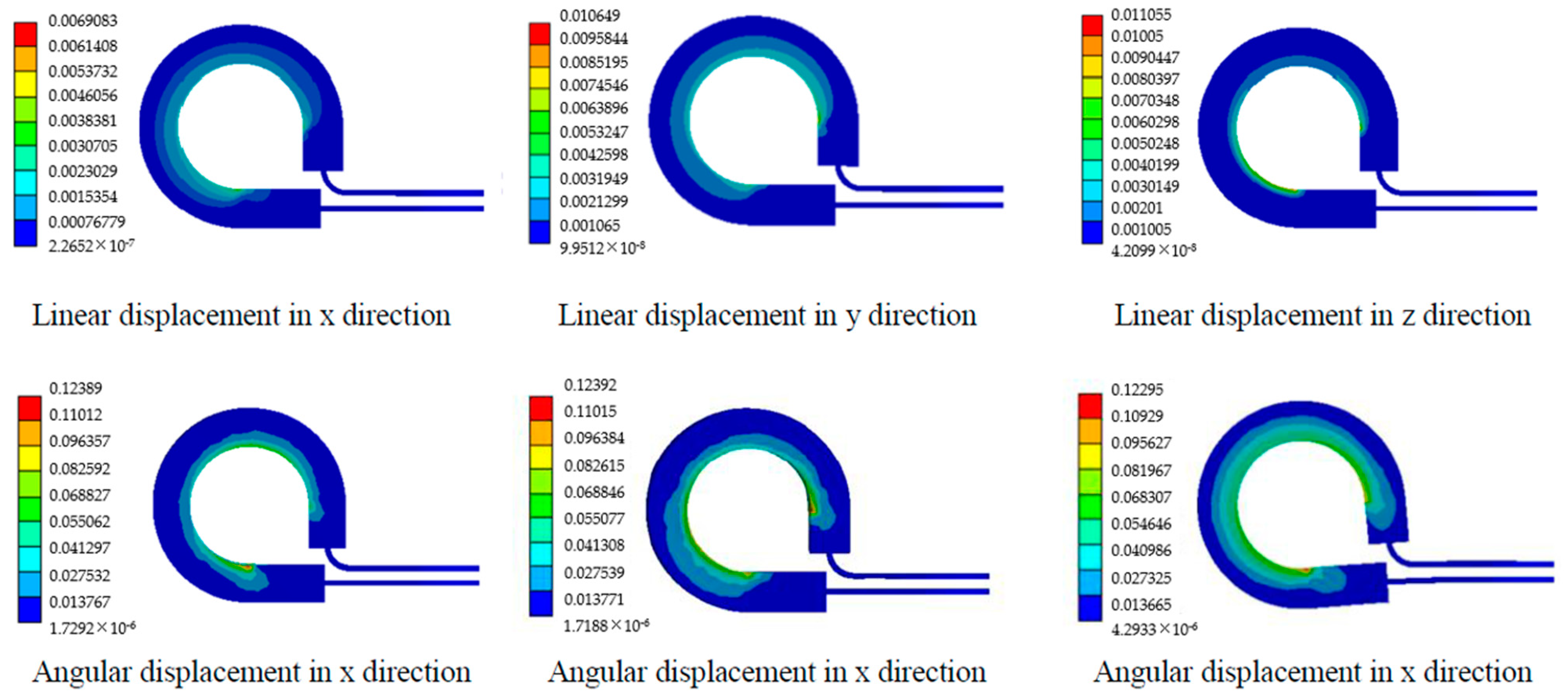
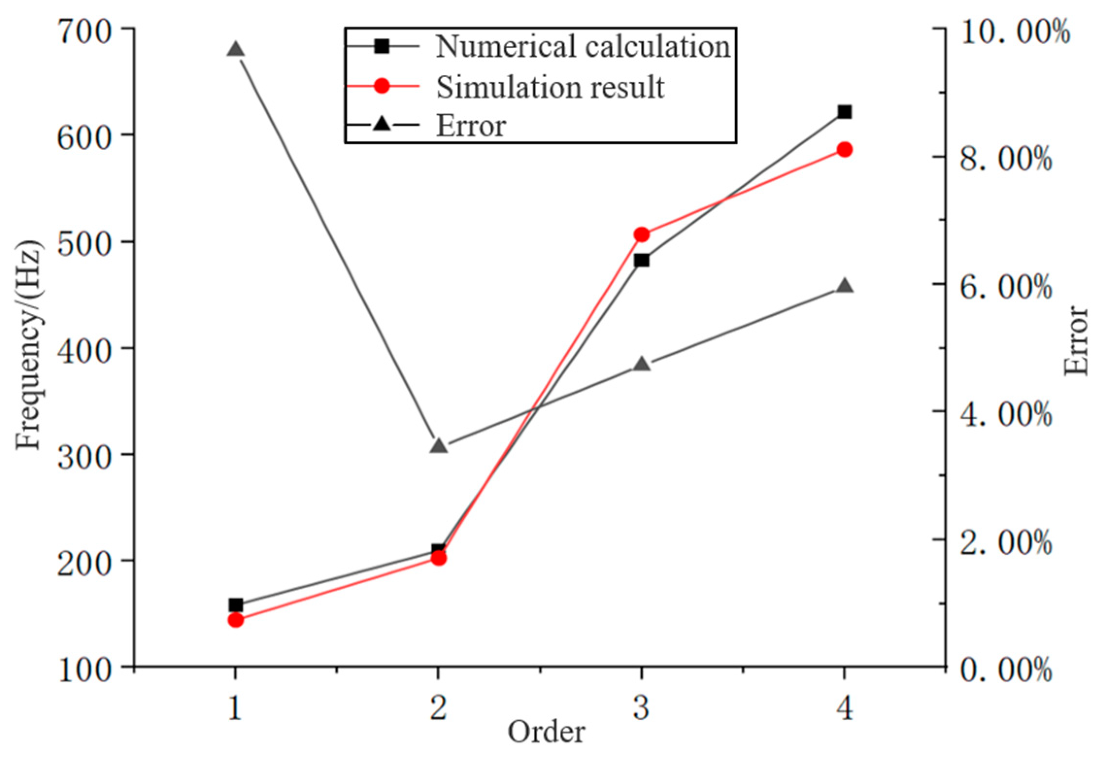
4.2. Simulation Results and Comparative Analysis

The finite element simulation of the liquid-filled pipeline is carried out. The cloud diagram of the vibration mode calculation results is shown in Figure 9. The simulation results of the filling pipeline are compared with the numerical results, and the results are shown in Table 5 and Figure 10.
It can be seen from the figure that the maximum error between the simulation results and the numerical results of the hydraulic pipeline appears at the first-order natural frequency, which is 9.66%. The error values at the second, third, and fourth order natural frequencies are 5.02%, 4.35%, and 5.4%, respectively, and the errors of the above results are within the acceptable range. This can explain the availability of the proposed vibration characteristic calculation model to a certain extent.

5. Conclusions

In this paper, the calculation model of the fluid–solid coupling vibration characteristics of pipeline systems, considering the influence of clamps, is established, and the following conclusions are obtained:
In this paper, the clamp in the pipeline system is equivalent to the combination of the constraint point and the pipeline, and the mechanical analysis of the pipelines on both sides of the constraint point is carried out. At the same time, considering the influence of the clamp stiffness on the pipeline system, a method for obtaining the equivalent stiffness of the clamp using finite element software is adopted by referring to the Aero-engine Design Manual and the existing research results. This method only needs to consider the displacement of force on the whole of the clamp when calculating and avoids the situation where the external force only exerts a large displacement on the surface rubber material, which affects the calculation of the overall stiffness of the clamp. Then, the fluid–solid coupling vibration model of the pipeline system is established by using the fluid–solid coupling 14-equation model, and the frequency domain solution is carried out.
The numerical results of an example show that the proposed modeling method for a piping system with clamps is effective. The method can be successfully applied to the analysis of the fluid–solid coupling vibration characteristics of liquid-filled piping systems.
Compared with previous research results, this study considers the influence of clamps in the pipeline system more carefully, which is more in line with the engineering practice. This modeling idea can be applied to the dynamics analysis of pipeline systems related to clamps in the future.

Author Contributions

Conceptualization, Y.L. and J.W.; methodology, J.W. and H.D.; software, H.D.; validation, Z.H. and F.Y.; formal analysis, Y.L.; investigation, J.W.; resources, H.D.; data curation, J.W. and H.D.; writing—original draft preparation, Y.L. and J.W.; writing—review and editing, H.D.; visualization, Y.L.; supervision, F.Y.; project administration, J.W.; funding acquisition, Y.L. All authors have read and agreed to the published version of the manuscript.

Funding

This research was funded by the Scientific Research Project of Tianjin Municipal Education Commission (No. 2020KJ017).

Data Availability Statement

The data used to support the findings of this study are included within the article.

Conflicts of Interest

The authors declare no conflict of interest.

References

  1. Liu, Y.; Xia, T.; Chen, Z.; Yan, G. The development of statistical contact model for rough surface. Tribology 2020, 40, 395–406. [Google Scholar] [CrossRef]
  2. Chen, Z.; Liu, Y.; Zhou, P. A comparative study of fractal dimension calculation methods for rough surface profiles. Chaos Solitons Fractals 2018, 112, 24–30. [Google Scholar] [CrossRef]
  3. Stosiak, M.; Karpenko, M.; Prentkovskis, O.; Deptuła, A.; Skačkauskas, P. Research of vibrations effect on hydraulic valves in military vehicles. Def. Technol. 2023; in press. [Google Scholar] [CrossRef]
  4. Chen, Z.; Zhang, X.; Zhou, P. Vibration fatigue life analysis of engine piping system based on multi-point random excitation. J. Propuls. Technol. 2019, 40, 1620–1627. [Google Scholar]
  5. Wu, J.; Zheng, S.; Wang, C.; Yu, Z. Study on pipeline self-excited vibration using transient fluid-structure coupling method. Int. J. Adv. Manuf. Technol. 2020, 107, 4055–4068. [Google Scholar] [CrossRef]
  6. Duan, J.; Li, C.; Jin, J. Modal analysis of tubing considering the effect of fluid-structure interaction. Energies 2022, 15, 670. [Google Scholar] [CrossRef]
  7. Gao, P.; Zhai, J.; Yan, Y.; Han, Q.; Qu, F.; Chen, X. A model reduction approach for the vibration analysis of hydraulic pipeline system in aircraft. Aerosp. Sci. Technol. 2016, 49, 144–153. [Google Scholar] [CrossRef]
  8. Xu, Y.Z.; Johnston, D.N.; Jiao, Z.X.; Plummer, A.R. Frequency modelling and solution of fluid–structure interaction in complex pipelines. J. Sound Vib. 2014, 333, 2800–2822. [Google Scholar] [CrossRef]
  9. Sadeghi, M.H.; Karimi-Dona, M.H. Dynamic behavior of a fluid conveying pipe subjected to a moving sprung mass—An fem-state space approach. Int. J. Press. Vessel. Pip. 2011, 88, 123–131. [Google Scholar] [CrossRef]
  10. Quan, L.; Che, S.; Guo, C.; Gao, H.; Guo, M. Axial vibration characteristics of fluid-structure interaction of an aircraft hydraulic pipe based on modified friction coupling model. Appl. Sci. 2020, 10, 3548. [Google Scholar] [CrossRef]
  11. Li, J.; Zhang, D.; Wang, L.; Lin, D.; Hong, J. Modal characteristics analysis for pipelines considering influence of fluid medium. J. Aerosp. Eng. 2019, 34, 671–677. [Google Scholar] [CrossRef]
  12. Quan, L.; Sun, B.; Zhao, J.; Li, D. Frequency response analysis of fluid-structure interaction vibration in aircraft bending hydraulic pipe. J. Northwestern Polytech. Univ 2018, 36, 487–495. [Google Scholar] [CrossRef]
  13. Ma, T.; Du, J.; Xu, D.; Dai, L.; Zhang, Y. Vibration characteristics analysis of fluid-conbeying pipe system with general elastic boundary supports. J. Vib. Eng. Technol. 2018, 31, 441–449. [Google Scholar] [CrossRef]
  14. Karpenko, M.; Prentkovskis, O.; Šukevičius, Š. Research on high-pressure hose with repairing fitting and influence on energy parameter of the hydraulic drive. Eksploat. Niezawodn. Maint. Reliab. 2022, 24, 25–32. [Google Scholar] [CrossRef]
  15. Liu, M.; Wang, Z.; Zhou, Z.; Qu, Y.; Yu, Z.; Wei, Q. Vibration response of multi-span fluid-conveying pipe with multiple accessories under complex boundary conditions. Eur. J. Mech. A-Solids 2018, 72, 41–56. [Google Scholar] [CrossRef]
  16. Lin, J.; Zhao, Y.; Zhu, Q.; Han, S.; Ma, H.; Ha, Q.K. Nonlinear characteristic of clamp loosing in aero-engine pipeline system. IEEE Access 2021, 9, 64076–64084. [Google Scholar] [CrossRef]
  17. Gao, Y.; Sun, W. Inverse identification of the mechanical parameters of a pipeline hoop and analysis of the effect of preload. Front. Mech. Eng. 2019, 14, 358–368. [Google Scholar] [CrossRef]
  18. Gao, Y.; Sun, W.; Piao, Y.; Ma, H. Inverse identification of support stiffness and damping of hoop based on measured FRF. J Aerosp. Eng. 2019, 34, 664–670. [Google Scholar] [CrossRef]
  19. Li, F.; Liu, W.; Wei, S.; Liu, Y. Research on equivalent stiffness and influence factors of aero-clamps for aircraft hydraulic pipeline. Mech. Sci. Technol. Aerosp. Eng. 2017, 36, 1472–1476. [Google Scholar] [CrossRef]
  20. Fei, C.; Han, Y.; Wen, J.; Li, C. Deep learning-based modeling method for probabilistic LCF life prediction of turbine blisk. Propul. Power Res. 2023; 13, online. [Google Scholar] [CrossRef]
  21. Gao, H. Modification of 14-Equation Model for Fluid-Structure Interaction and Vibration Characteristic Analysis of Hydraulic Pipeline. Master’s Thesis, Yanshan University, Qinhuangdao, China, 2021. [Google Scholar] [CrossRef]
  22. Li, S. Dynamic Analysis of Fluid-Structure Interaction of Pipe Systems Conveying Fluid. Ph.D. Dissertation, Harbin Engineering University, Harbin, China, 2015. [Google Scholar]
  23. Aero-Engine Design Manual Editorial Committee. Aero-Engine Design Manual, 19th ed.; Aviation Industry Press: Beijing, China, 2000; pp. 320–324. [Google Scholar]
  24. Editorial Committee of China Aviation Materials Handbook. China Aviation Materials Handbook, 3rd ed.; Standards Press of China: Beijing, China, 1988; pp. 117–190. [Google Scholar]
  25. Che, S. Frequency Domain Characteristic Analysis of Fluid-Structure Interaction Vibration of Civil Aircraft Fuel Pipeline. Master’s Thesis, Yanshan University, Qinhuangdao, China, 2021. [Google Scholar] [CrossRef]
  26. Qiu, M.; Chen, Z.; Wang, J.; Liu, Z.; Zhao, W. Experiment and numerical analysis of natural frequency for liquid-filled pipe. J. Propuls. Power 2013, 34, 1537–1542. [Google Scholar] [CrossRef]
Figure 1. Piping force diagram.
Aerospace 10 00900 g001
Figure 2. Concentrated mass point.
Aerospace 10 00900 g002
Figure 3. Discrete clamp model.
Aerospace 10 00900 g003
Figure 4. (a) Clamp finite element model; (b) grid division of clamp model.
Aerospace 10 00900 g004
Figure 5. Displacement of clamp in all directions (unit: mm).
Aerospace 10 00900 g005
Figure 6. Structure diagram of pipeline.
Aerospace 10 00900 g006
Figure 7. Axial vibration characteristics of hydraulic pipeline under different speeds. (a) V = 1 m/s; (b) V = 3 m/s; (c) V = 5 m/s.
Aerospace 10 00900 g007
Figure 8. Simulation model of the pipeline system.
Aerospace 10 00900 g008
Figure 9. 1–4 order vibration shape cloud map of air traffic pipeline. (a) First-order mode cloud diagram. (b) Second-order mode cloud diagram. (c) The cloud diagram of the third-order mode. (d) Fourth-order mode cloud diagram.
Aerospace 10 00900 g009
Figure 10. Results comparison of liquid-filled pipes.
Aerospace 10 00900 g010
Table 1. Clamp-related material parameters.
Clamping Strap Material ParametersDensity/kg·m−3Poisson RatioElastic Modulus/MPa
79300.331.86 × 105
Rubber material parameterC10C0D0
0.7740.1930.025
Table 2. Measured value of clamp-equivalent stiffness.
Linear Stiffnesskx/(N/m)Ky/(N/m)Ky/(N/m)
4.97 × 1052.64 × 1054.21 × 105
Angular stiffnessKyz/(N/m)Kxz/(N/m)Kxy/(N/m)
0206.7891.1557.4
Table 3. Correlation parameters of the piping system.
Parameter
Title 2
Value
Tube length L1/(mm)200
Tube length L2/(mm)500
Tube length L3/(mm)200
Clamp width Lc/(mm)200
Thickness of pipe wall/(mm)1
Inner radius/(mm)5.4
Poisson ratio0.33
Pipeline density/(kg/m3)7930
Shear modulus/(Pa)6.99 × 1010
Young’s modulus/(Pa)1.86 × 1011
Fluid density/(kg/m3)1000
Table 4. Pipeline pressure pulsation information.
Average Fluctuating Pressure/MPaPeak Value/MPaFrequency/Hz
161.540
Table 5. Results comparison of liquid-filled pipes.
Order1234
Numerical calculation154.41208.8480.57617.32
Simulation result139.49198.31501.49584
Error9.66%5.02%4.35%5.4%
Disclaimer/Publisher’s Note: The statements, opinions and data contained in all publications are solely those of the individual author(s) and contributor(s) and not of MDPI and/or the editor(s). MDPI and/or the editor(s) disclaim responsibility for any injury to people or property resulting from any ideas, methods, instructions or products referred to in the content.

