
Doppler-Aided Positioning for Fused LEO Navigation Systems


Abstract
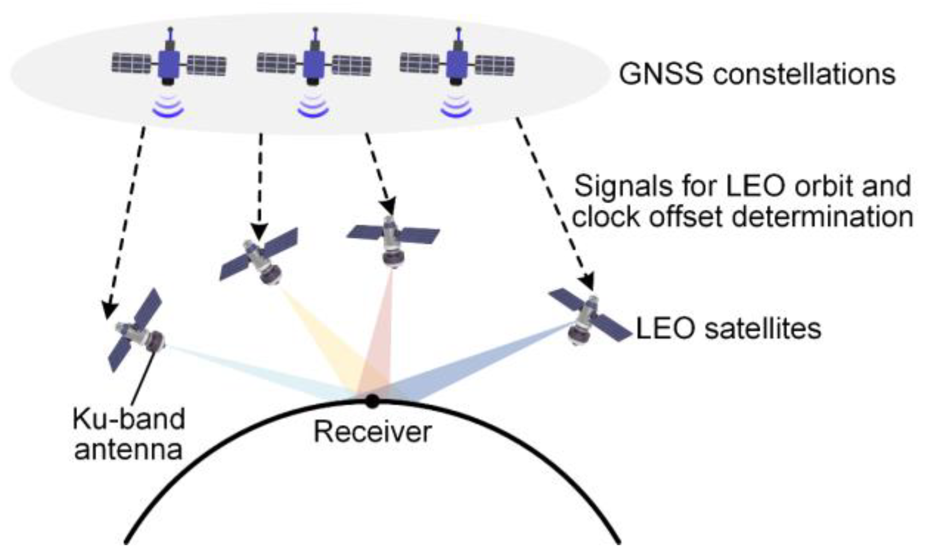
:1. Introduction
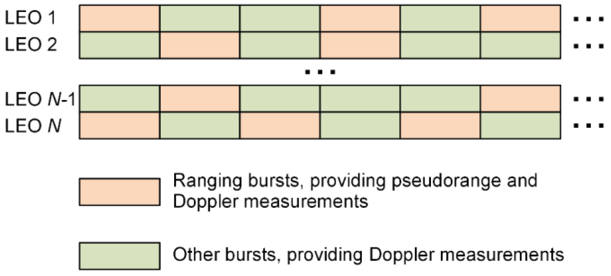
2. Doppler-Aided Positioning for Fused LEO Navigation Systems
2.1. Prince of Doppler-Aided Positioning
2.2. Weighted Least Squares Method
3. Positioning Error Analysis
4. Doppler-Aided Positioning Simulation Results
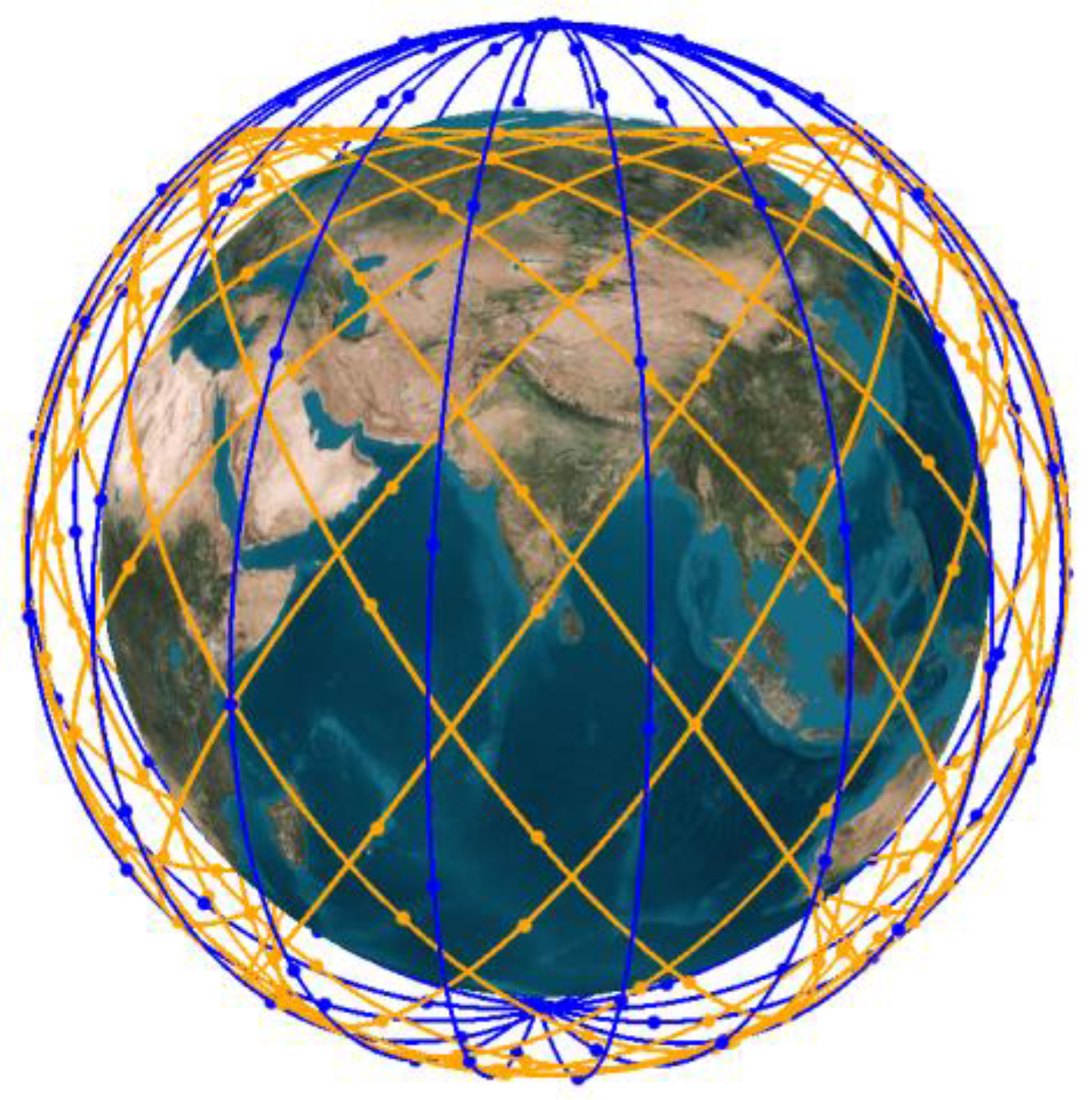
4.1. Simulation Parameters
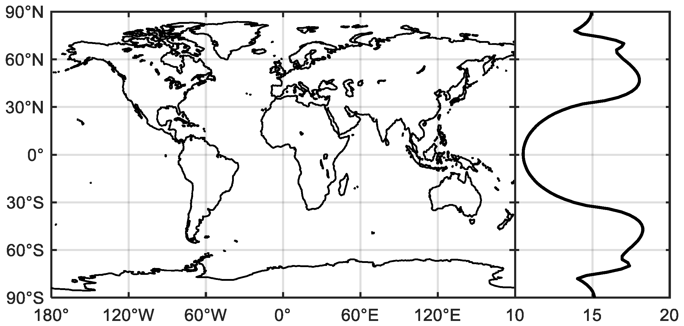
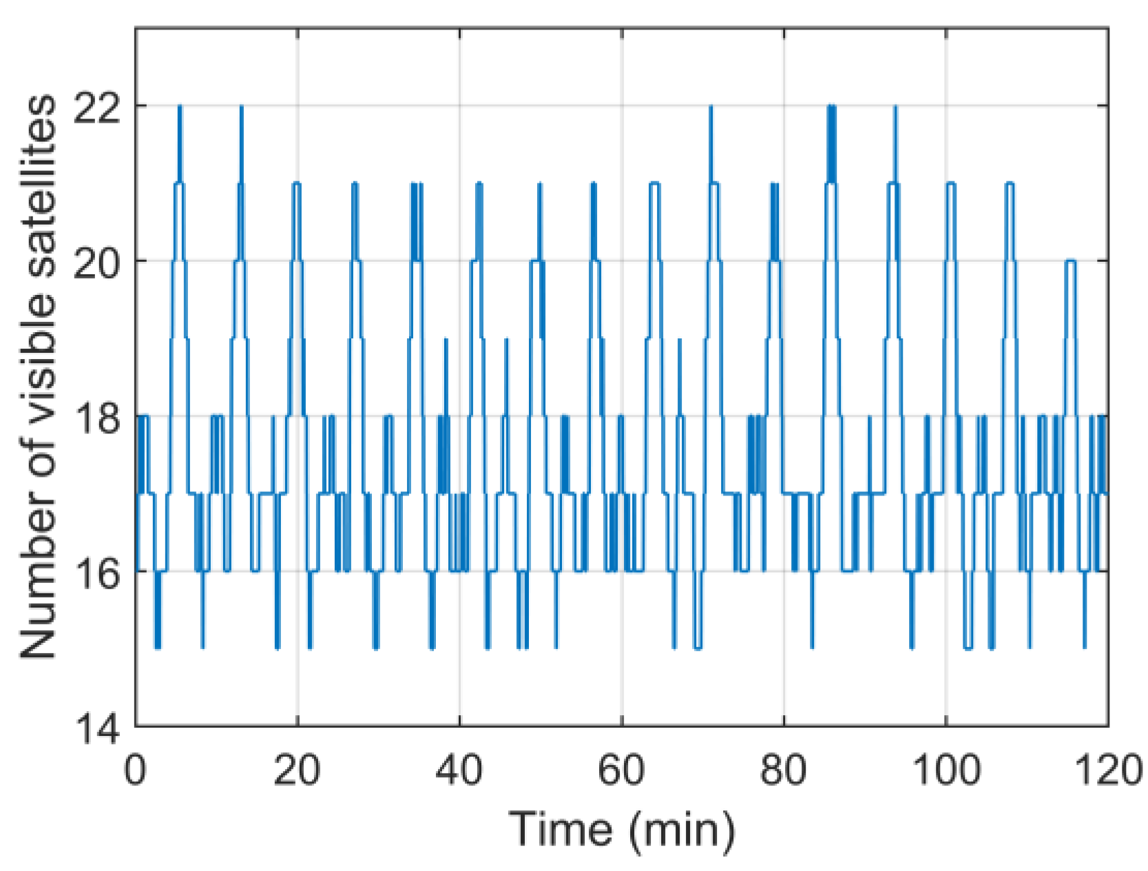
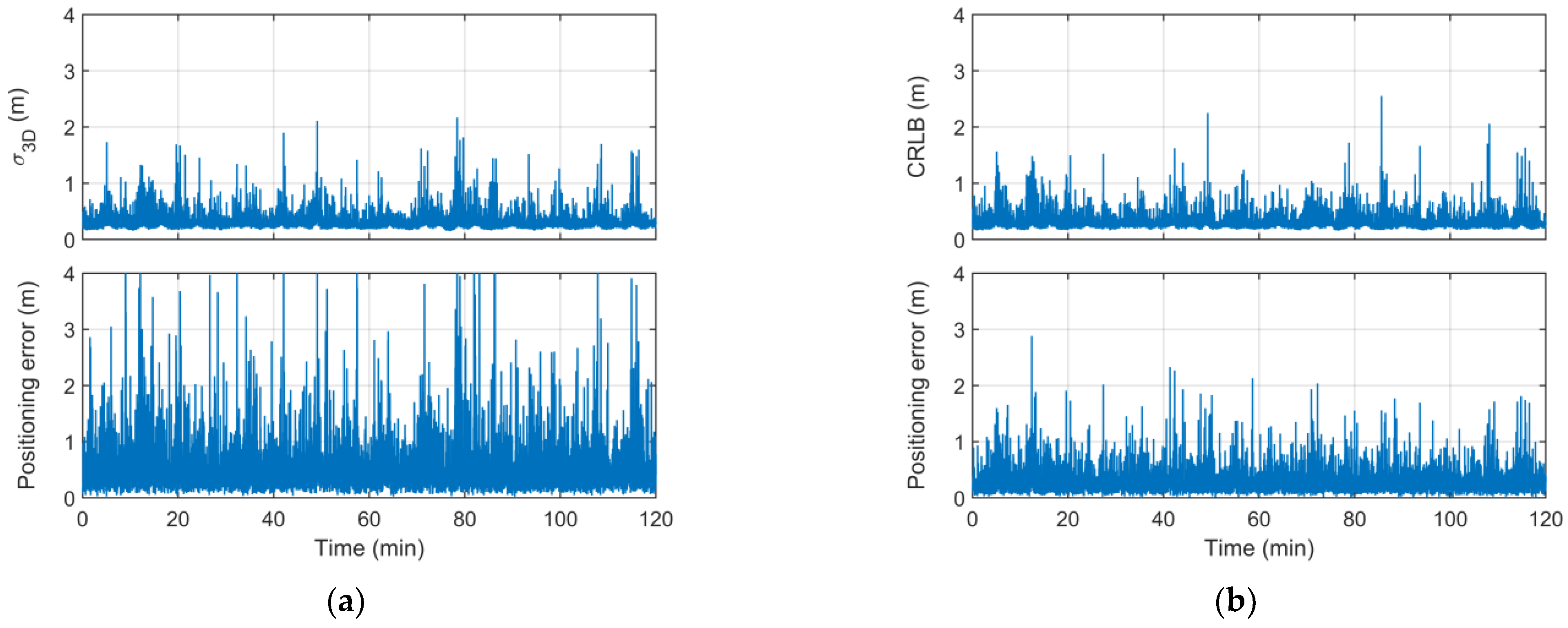
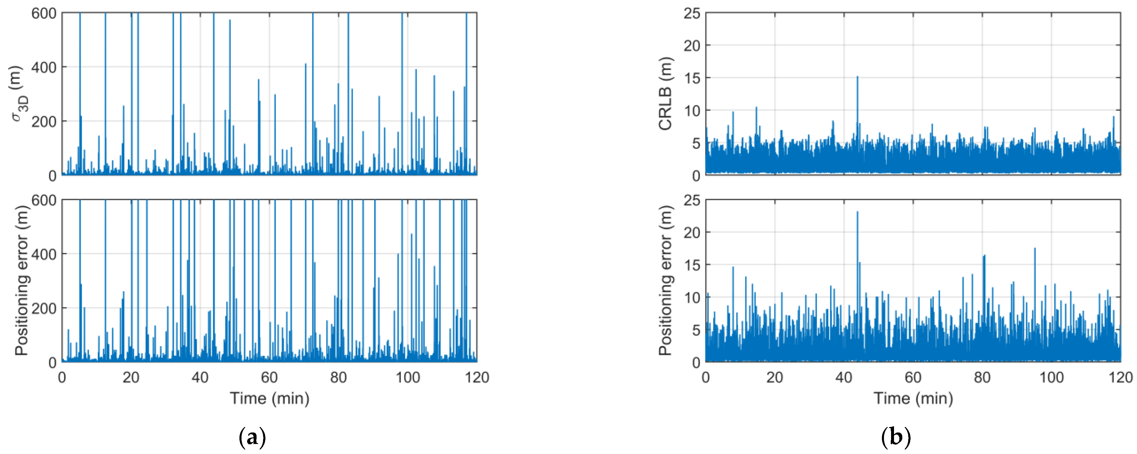
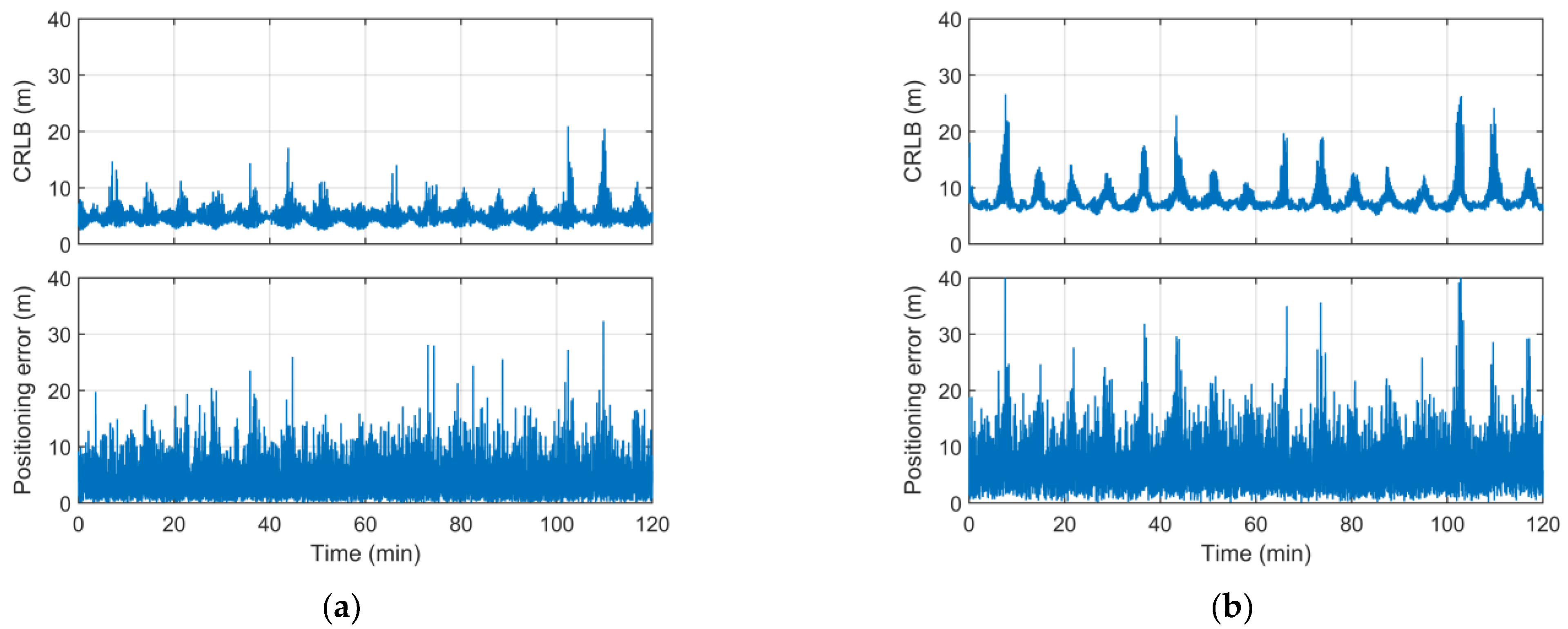
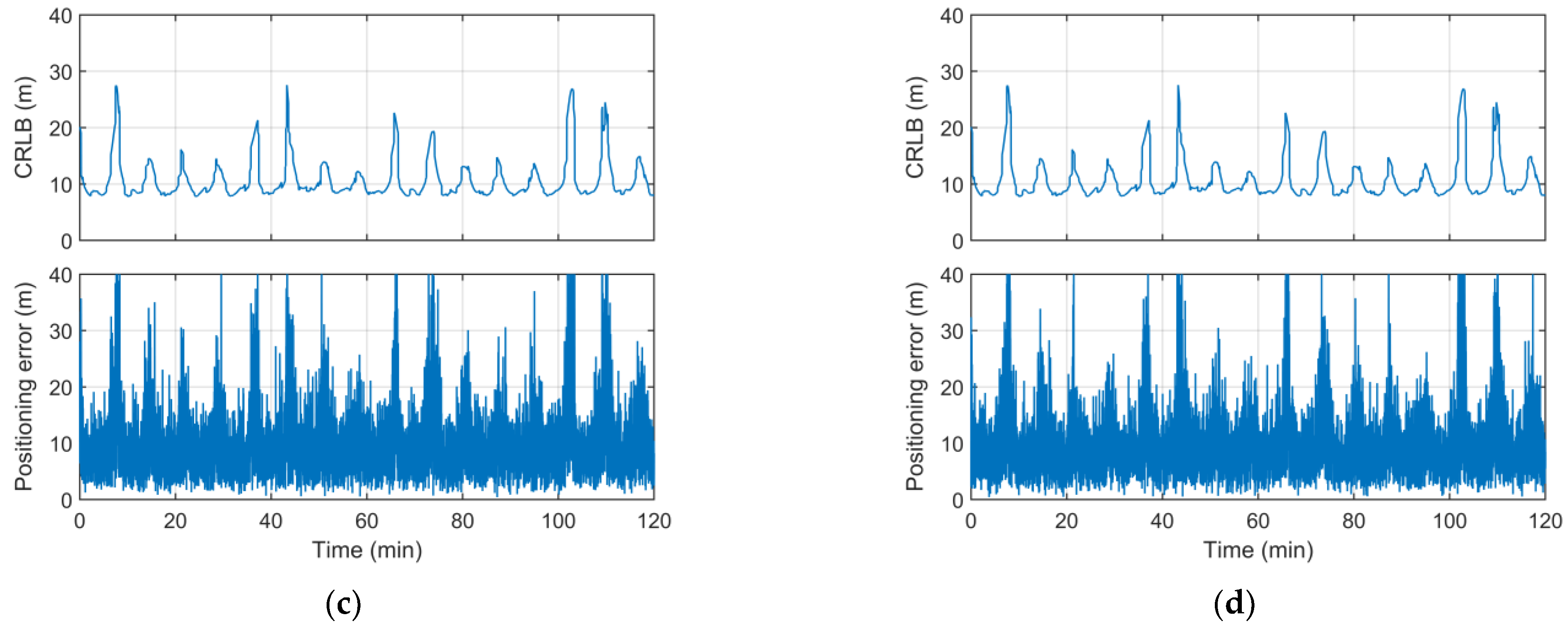
4.2. Simulated Positioning Results
5. Discussion
6. Conclusions
Author Contributions
Funding
Data Availability Statement
Conflicts of Interest
References
- Ruan, Y.; Hu, M.; Yun, C. Advances and prospects of the configuration design and control research of the LEO mega-constellations. Chin. Space Sci. Technol. 2022, 42, 1–15. [Google Scholar]
- Ge, H.; Li, B.; Jia, S.; Nie, L.; Wu, T.; Yang, Z.; Shang, J.; Zheng, Y.; Ge, M. LEO Enhanced Global Navigation Satellite System (LeGNSS): Progress, opportunities, and challenges. Geo Spat. Inf. Sci. 2022, 25, 1–13. [Google Scholar] [CrossRef]
- Prol, F.S.; Ferre, R.M.; Saleem, Z.; Välisuo, P.; Pinell, C.; Lohan, E.S.; Elsanhoury, M.; Elmusrati, M.; Islam, S.; Celikbilek, K.; et al. Position, navigation, and timing (PNT) through low earth orbit (LEO) satellites: A survey on current status, challenges, and opportunities. IEEE Access 2022, 10, 83971–84002. [Google Scholar] [CrossRef]
- Li, B.; Ge, H.; Ge, M.; Nie, L.; Shen, Y.; Schuh, H. LEO enhanced Global Navigation Satellite System (LeGNSS) for real-time precise positioning services. Adv. Space Res. 2019, 63, 73–93. [Google Scholar] [CrossRef]
- Li, X.; Ma, F.; Li, X.; Lv, H.; Bian, L.; Jiang, Z.; Zhang, X. LEO constellation-augmented multi-GNSS for rapid PPP convergence. J. Geod. 2019, 93, 749–764. [Google Scholar] [CrossRef]
- Lawrence, D.; Cobb, H.S.; Gutt, G.; Tremblay, F.; Laplante, P.; O’Connor, M. Test Results from a LEO-Satellite-Based Assured Time and Location Solution. In Proceedings of the 2016 International Technical Meeting of the Institute of Navigation, Monterey, CA, USA, 25–28 January 2016. [Google Scholar]
- Reid, T.G.; Neish, A.M.; Walter, T.F.; Enge, P.K. Leveraging commercial broadband LEO constellations for navigating. In Proceedings of the 29th International Technical Meeting of the Satellite Division of The Institute of Navigation (ION GNSS+ 2016), Portland, OR, USA, 12–16 September 2016. [Google Scholar]
- Xiao, Y.; Li, L.; Chang, J.; Yu, J.; Gong, W.; Liang, G. Navigation Method for Terrestrial Users Based on Beidou Ka Inter Satellite Links. Chin. J. Aeronaut. 2019, 40, 320. [Google Scholar]
- Khalife, J.; Neinavaie, M.; Kassas, Z.M. Blind Doppler tracking from OFDM signals transmitted by broadband LEO satellites. In Proceedings of the 2021 IEEE 93rd Vehicular Technology Conference (VTC2021-Spring), Helsinki, Finland, 25–28 April 2021. [Google Scholar]
- Orabi, M.; Khalife, J.; Kassas, Z.M. Opportunistic navigation with Doppler measurements from Iridium Next and Orbcomm LEO satellites. In Proceedings of the 2021 IEEE Aerospace Conference (50100), Big Sky, MT, USA, 6–13 March 2021. [Google Scholar]
- Neinavaie, M.; Khalife, J.; Kassas, Z.M. Acquisition, Doppler tracking, and positioning with Starlink LEO satellites: First results. IEEE Trans. Aerosp. Electron. Syst. 2021, 58, 2606–2610. [Google Scholar] [CrossRef]
- Khalife, J.; Neinavaie, M.; Kassas, Z.M. The first carrier phase tracking and positioning results with Starlink LEO satellite signals. IEEE Trans. Aerosp. Electron. Syst. 2021, 58, 1487–1491. [Google Scholar] [CrossRef]
- Iannucci, P.A.; Humphreys, T.E. Economical fused LEO GNSS. In Proceedings of the 2020 IEEE/ION Position, Location and Navigation Symposium (PLANS), Portland, OR, USA, 20–23 April 2020. [Google Scholar]
- Iannucci, P.A.; Humphreys, T.E. Fused low-Earth-orbit GNSS. In IEEE Transactions on Aerospace and Electronic Systems; IEEE: Piscataway, NJ, USA, 2022; p. 1. [Google Scholar]
- Bahrami, M. Getting back on the sidewalk: Doppler-aided autonomous positioning with single-frequency mass market receivers in urban areas. In Proceedings of the 22nd International Technical Meeting of The Satellite Division of the Institute of Navigation (ION GNSS 2009), Savannah, GA, USA, 22–25 September 2009. [Google Scholar]
- Chen, H.W.; Wang, H.S.; Chiang, Y.T.; Chang, F.R. A new coarse-time GPS positioning algorithm using combined Doppler and code-phase measurements. GPS Solut. 2014, 18, 541–551. [Google Scholar] [CrossRef]
- Li, L.; Zhong, J.; Zhao, M. Doppler-aided GNSS position estimation with weighted least squares. IEEE Trans. Veh. Technol. 2011, 60, 3615–3624. [Google Scholar] [CrossRef]
- Vincent, F.; Vilà-Valls, J.; Besson, O.; Medina, D.; Chaumette, E. Doppler-aided positioning in GNSS receivers-A performance analysis. Signal Process. 2020, 176, 107713. [Google Scholar] [CrossRef]
- Jiang, M.; Qin, H.; Zhao, C.; Sun, G. LEO Doppler-aided GNSS position estimation. GPS Solut. 2022, 26, 31. [Google Scholar] [CrossRef]
- Kay, S.M. Fundamentals of Statistical Signal Processing; Prentice Hall: Englewood Cliffs, NJ, USA, 1993. [Google Scholar]
- Psiaki, M.L. Navigation using carrier Doppler shift from a LEO constellation: TRANSIT on steroids. Navigation 2021, 68, 621–641. [Google Scholar] [CrossRef]


| Parameters | LEO Constellation | |
|---|---|---|
| Configuration | Near-polar orbit | Walker |
| Number of satellites | 120 | 270 |
| Number of orbital planes | 10 | 18 |
| Number of satellites per orbital plane | 12 | 15 |
| Orbital height | 1050 km | 1000 km |
| Orbital inclination | 89° | 55° |
| Eccentricity | 0 | 0 |
| Simulation Parameters | Value |
|---|---|
| Position | BJF1: 39.61° N, 115.89° E, 87.47 m |
| Frequency | 12 GHz |
| User ranging error | 0.105 m |
| RMS error of satellite orbit | R: 0.059 m, A: 0.093 m, C: 0.083 m |
| Satellite clock offset RMS error | 0.022 m |
| Frequency measurement accuracy | 1 Hz |
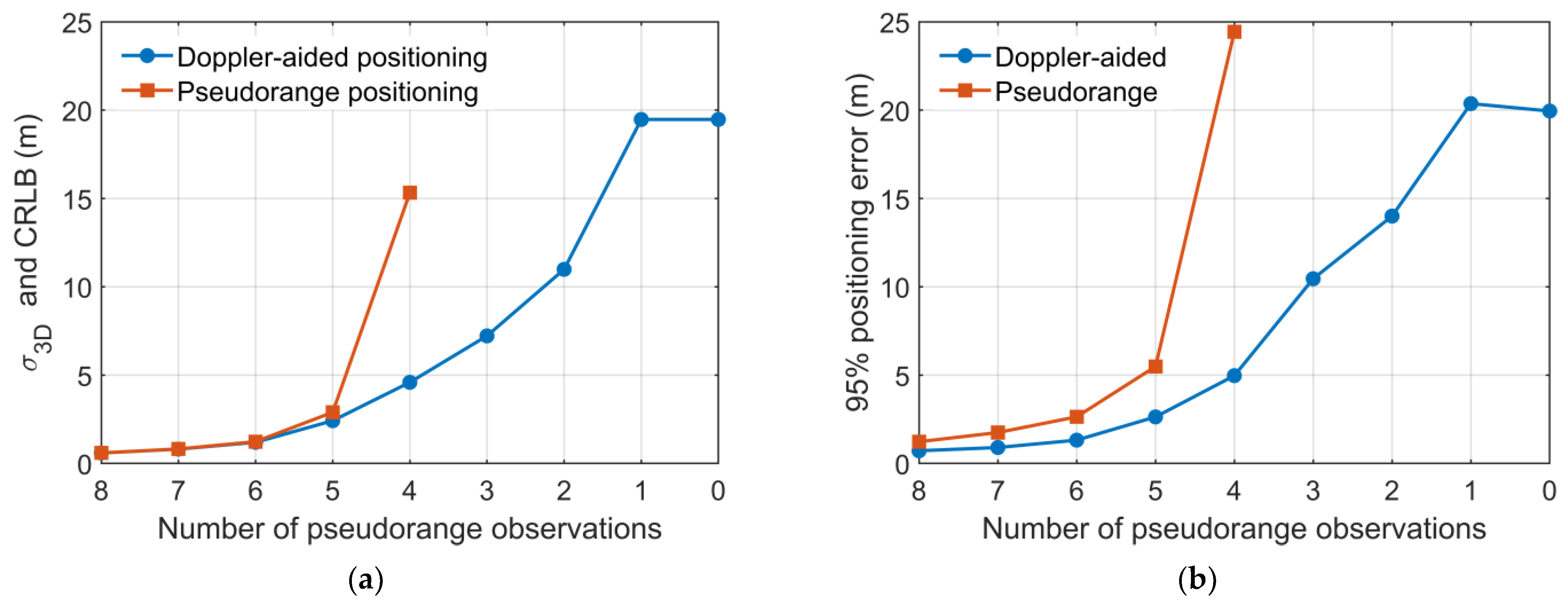
| Number of Pseudorange Measurements | Doppler-Aided Positioning | Pseudorange Positioning | Increase Amplitude |
|---|---|---|---|
| 8 | 0.72 m | 1.23 m | 41.46% |
| 7 | 0.90 m | 1.75 m | 48.57% |
| 6 | 1.32 m | 2.64 m | 49.98% |
| 5 | 2.64 m | 5.49 m | 51.91% |
| 4 | 4.97 m | 24.43 m | 79.66% |
| 3 | 10.46 m | - | - |
| 2 | 14.00 m | - | - |
| 1 | 20.37 m | - | - |
| 0 | 19.95 m | - | - |
Disclaimer/Publisher’s Note: The statements, opinions and data contained in all publications are solely those of the individual author(s) and contributor(s) and not of MDPI and/or the editor(s). MDPI and/or the editor(s) disclaim responsibility for any injury to people or property resulting from any ideas, methods, instructions or products referred to in the content. |
© 2023 by the authors. Licensee MDPI, Basel, Switzerland. This article is an open access article distributed under the terms and conditions of the Creative Commons Attribution (CC BY) license (https://creativecommons.org/licenses/by/4.0/).
Share and Cite
Wang, W.; Lu, Z.; Tian, Y.; Bian, L.; Wang, G.; Zhang, L. Doppler-Aided Positioning for Fused LEO Navigation Systems. Aerospace 2023, 10, 864. https://doi.org/10.3390/aerospace10100864
Wang W, Lu Z, Tian Y, Bian L, Wang G, Zhang L. Doppler-Aided Positioning for Fused LEO Navigation Systems. Aerospace. 2023; 10(10):864. https://doi.org/10.3390/aerospace10100864
Chicago/Turabian StyleWang, Weiwei, Zhangjian Lu, Ye Tian, Lang Bian, Guoyong Wang, and Lixin Zhang. 2023. "Doppler-Aided Positioning for Fused LEO Navigation Systems" Aerospace 10, no. 10: 864. https://doi.org/10.3390/aerospace10100864