
Aero-Engine Rotor Assembly Process Optimization Based on Improved Harris Hawk Algorithm
Abstract
:1. Introduction

| Reference | Algorithm | Advantages and Disadvantages of Algorithm |
|---|---|---|
| Literature [27] | ACO | The fast convergence speed and low diversity of the population are not conducive to improving the global optimization ability of the algorithm. |
| Literature [29] | GA | Fast and random search capability, with potential parallelism, so the search speed of the algorithm is relatively slow |
| Literature [30] | IA | Immune algorithm has the advantages of adaptability, randomness, parallelism, global convergence, population diversity |
| Literature [31] | SSA | The algorithm has fast convergence speed and strong global search ability. |
| Literature [32] | GWO | It has the characteristics of strong convergence, few parameters and easy realization. |
| Literature [33] | IFPA | It is easy to fall into local optimum, and the convergence speed is slow in the later stage |
2. Single Stage Disc and Blade Optimization Model
3. Optimum Assembly Model of Multi-Stage Disc Rotor
4. Harris Hawk Optimization Algorithm
4.1. Exploration Phase
4.2. Development Phase
4.2.1. Soft Surrounding
4.2.2. Hard Surrounding
4.2.3. Progressive Rapid Subduction Soft Surrounding
4.2.4. Progressive Rapid Subduction Hard Surrounding
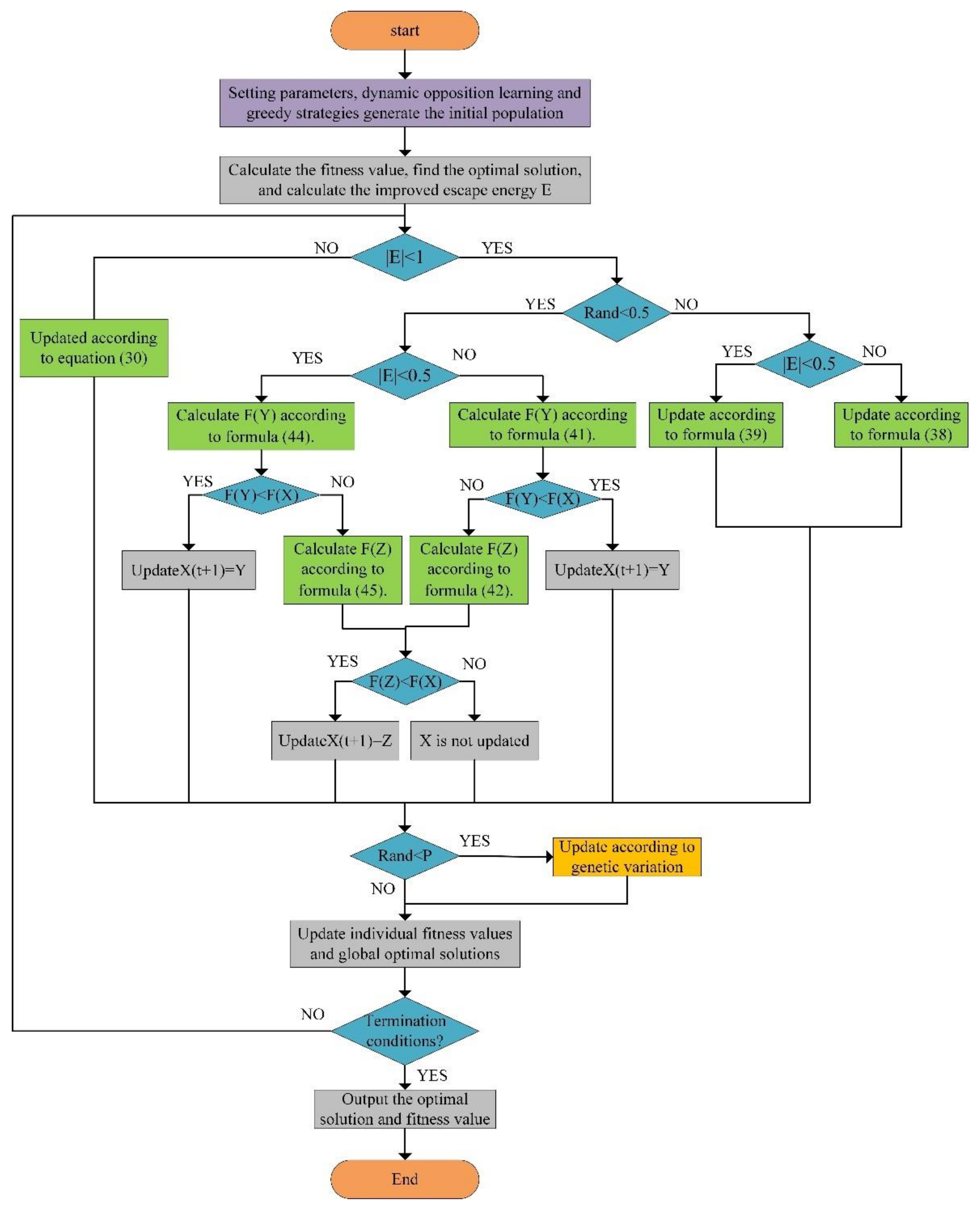
5. Improved Discrete Harris Hawk Algorithm
5.1. Initial Population Generation of Dynamic Opposing Learning
5.2. The Improved Escape Energy Function
5.3. Discrete Exploration for Whale Optimization
- (1)
- A new assembly sequence is obtained by subtracting assembly sequence from . Considering that the result will be negative, the absolute value is adopted. The calculation formula is as Equation (33).
- (2)
- Array multiplication, corresponding value multiplication, the rules are as follows:
- (3)
- Arrays are added and corresponding values are added according to the following rules as Equation (35).
- (4)
- is an -dimensional integer array randomly generated by Levy distribution. The values of the array are generated by the Formula (24). The characteristics of LF are that it generates a small number in most of the time and suddenly jumps to a very large number randomly, thus mimicking the Levy flight behavior of birds. is an -dimensional array of numbers 0 and 1 that are generated.
- (1)
- Statistically identify the values in the array that exceed the maximum number of blades and repeat the values, and change these values to 0. At the same time, record the missing values and the number of values in the sequence.
- (2)
- The missing value is randomly filled into the position of 0 in the array to get a new sequence.
- (3)
- To satisfy the constraints and generate the optimal sequence which meets the conditions, the assembly sequence is updated. The update rule is to exchange the blades which do not meet the conditions randomly until the conditional output is met.
5.4. Discrete Development Method of Adaptive Weighting
5.4.1. Discrete Soft Surrounding
5.4.2. Discrete Hard Surrounding
5.4.3. Discrete Progressive Rapid Subduction Soft Surrounding
5.4.4. Discrete Progressive Rapid Subduction Hard Surrounding
5.5. Genetic Operator Variation
5.6. Improving the Procedure of Harris Hawk Algorithm Implementation
6. Instance Validation
6.1. Single Stage Disc and Single Stage Blade Assembly
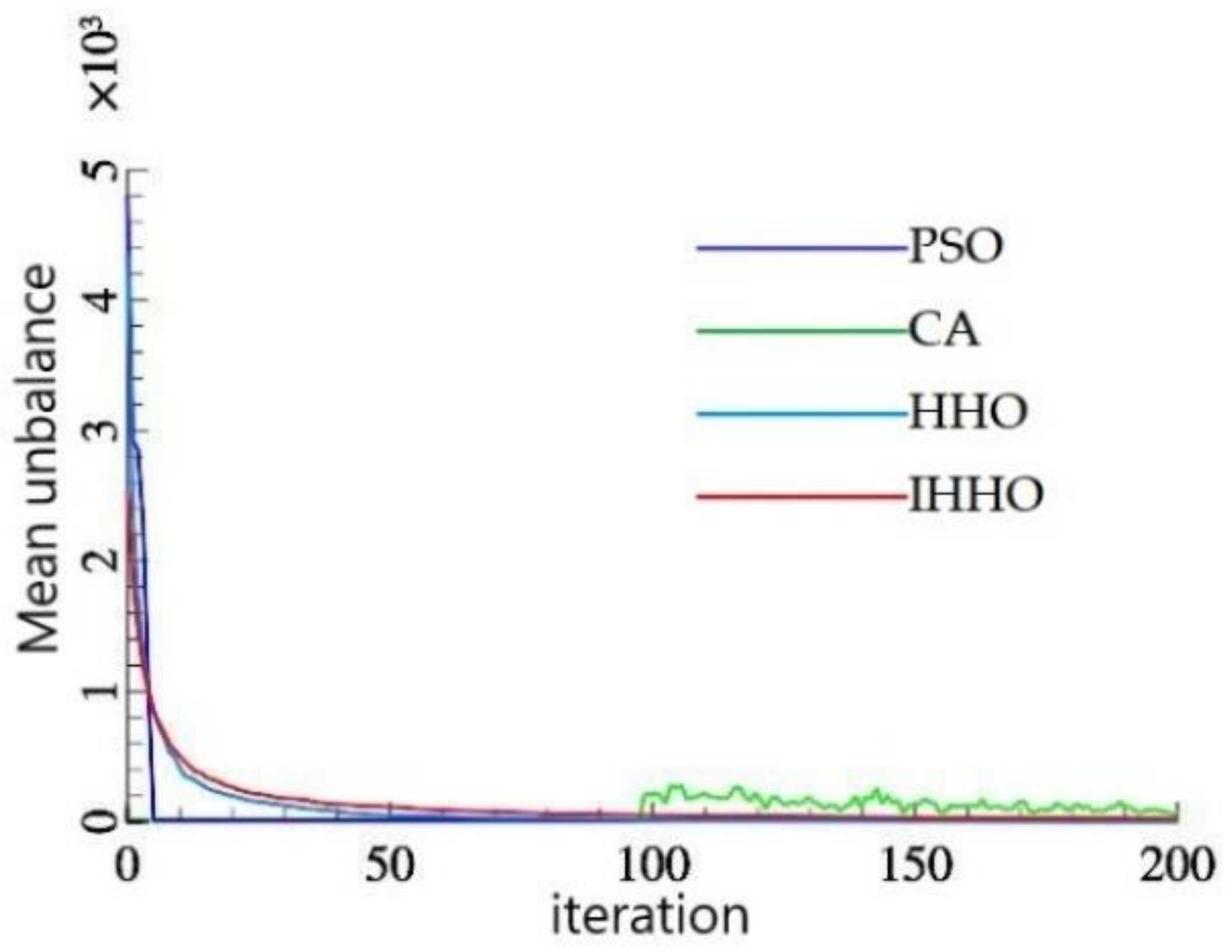
6.2. Rotor Multistage Disc Phase Assembly
Analysis
7. Conclusions
- For the optimization of single stage disc and blade assembly unbalance, the improved Harris Hawk optimization algorithm is compared with the particle swarm optimization, the genetic algorithm, and the Harris Hawk optimization algorithm, and the unbalance of the optimal blade assembly sequence is reduced by 91.75%, 99.82%, and 83.39%, respectively;
- For the assembly of each stage disc blade of the engine rotor, the results of the improved Harris Hawk optimization algorithm, particle swarm optimization algorithm, genetic algorithm, and Harris Hawk optimization algorithm are compared and analyzed. The optimal unbalance of the improved Harris Hawk optimization algorithm is reduced by 79.71%, 99.48%, and 54.92%, respectively. The proposed IHHO algorithm is obviously superior to the other three algorithms in finding the optimal solution;
- The phase angle of the multistage blade assembly is optimized by improving the Harris Hawk optimization algorithm. The total residual unbalanced force, unbalanced torque, and blade assembly phase angle of each stage before and after optimization are compared. The optimized assembly phase angles are 247°, 92°, 261°, 0°, 115°. The total residual unbalanced force and moment of assembly are 0.0167 and 0.0124, and the total residual unbalanced force and moment of assembly after optimization are 84.22% and 98.05% lower than those before optimization.
Author Contributions
Funding
Data Availability Statement
Acknowledgments
Conflicts of Interest
References
- Liu, Y.M.; Zhang, M.W.; Sun, C.Z.; Hu, M.; Chen, D.Y.; Liu, Z.W.; Tan, J.B. A method to minimize stage-by-stage initial unbalance in the aero engine assembly of multistage rotors. Aerosp. Sci. Technol. 2019, 85, 270–276. [Google Scholar] [CrossRef]
- Chen, D. Research on Vibration Suppression Method of Aero-Engine Rotor Based on Stack Assembly Optimization. Master’s Thesis, Harbin Institute of Technology, Harbin, China, 2019. [Google Scholar]
- Lin, Z. Research on Rotor Assembly Method Based on Axial Compression; Harbin Institute of Technology: Harbin, China, 2018. [Google Scholar]
- Zhang, H.; Wang, M.; Li, Z.; Zhou, J.; Zhang, K.; Ma, X.; Wang, M. Semi-Physical Simulation of Fan Rotor Assembly Process Optimization for Unbalance Based on Reinforcement Learning. Aerospace 2022, 9, 342. [Google Scholar] [CrossRef]
- Abdullah, M.A.; Ab, R.M.F.F.; Ghazalli, Z. Optimization of assembly sequence planning using soft computing approaches: A review. Arch. Comput. Methods. Eng. 2019, 26, 461–474. [Google Scholar] [CrossRef]
- Liu, L.K.; LI, L.L. Optimization of Assembly Sequence Planning of Turbine Low-pressure Rotor Blades Based on the Improved Simulated Annealing Algorithm. J. Phys. Conf. Ser. 2021, 1939, 012098. [Google Scholar]
- Zhao, L.P.; Li, B.H.; Chen, H.R.; Zhao, L.P. An assembly sequence optimization oriented small world networks genetic algorithm and case study. Assem. Autom. 2018, 38, 387–397. [Google Scholar] [CrossRef]
- Li, L.L.; Chen, K.; Gao, J.M.; Liu, J.K. Research on Optimizing Selection and Optimizing Matching Technologies of Aeroengine Fan Rotor Blades. Shock Vib. 2021, 2021, 5595535. [Google Scholar] [CrossRef]
- Li, L.L.; Chen, K.; Gao, J.M.; Liu, J.K.; Gao, Z.Y.; Dai, H.W. Research on optimizing-assembly and optimizing-adjustment technologies of aero-engine fan rotor blades. Adv. Eng. Inform. 2022, 51, 101506. [Google Scholar] [CrossRef]
- Zhu, M.Y.; Li, M.Q.; Wen, X.; Li, D.Y. Intelligent optimization of turbine rotor blade assembly sequence. J. Aerosp. Power. 2017, 32, 2536–2543. [Google Scholar]
- Pitsoulis, L.S.; Pardalos, P.M.; Hearn, D.W. Approximate solutions to the turbine balancing problem. Eur. J. Oper. Res. 2001, 130, 147–155. [Google Scholar] [CrossRef]
- Wang, L.; Wang, T.G.; Luo, W.Y. Improved non-dominated sorting genetic algorithm (NSGA)-II in multi-objective optimization studies of wind turbine blades. Appl. Math. Mech. Engl. Ed. 2011, 32, 739–748. [Google Scholar] [CrossRef]
- Tu, J.B.; Li, Z.; Ge, H.T.; Liu, L.; Liu, H.H. Multi-objective optimization of rotor-stack assembly based on geometric algebra theory. Acta Aeronaut. Astronaut. Sin. 2021, 42, 395–405. [Google Scholar]
- Zhang, Z.H.; Guo, J.K.; Hong, J.; Sun, Y.H. Application study intelligent algorithms for prediction and phase optimization of assembly eccentricity of aero-engine high pressure rotor. J. Xi’an Jiaotong Univ. 2021, 55, 47–54. [Google Scholar]
- Chen, Y.; Cui, J.; Sun, X. A Vibration Suppression Method for the Multistage Rotor of an Aero-Engine Based on Assembly Optimization. Machines 2021, 9, 189. [Google Scholar] [CrossRef]
- Zhang, Y.; He, L.; Yang, J.; Wang, J.; Zhu, G. Vibration control of tie rod rotors with optimization of unbalanced force and unbalanced moment. IEEE Access 2020, 8, 66578–66587. [Google Scholar] [CrossRef]
- Zhao, B.; Yuan, Q.; Li, P. Improvement of the vibration performance of rod-fastened rotor by multi optimization on the distribution of original bending and unbalance. J. Mech. Sci. Technol. 2020, 34, 83–95. [Google Scholar] [CrossRef]
- Chen, Y.; Cui, J.; Sun, X. An Assembly Method for the Multistage Rotor of An Aero-Engine Based on the Dual Objective Synchronous Optimization for the Coaxality and Unbalance. Aerospace 2021, 8, 94. [Google Scholar] [CrossRef]
- Wang, L.; Sun, C.; Tan, J.; Zhao, B.; Wan, G. Improvement of location and orientation tolerances propagation control in cylindrical components assembly using stack-build assembly technique. Assem. Autom. 2015, 35, 358–366. [Google Scholar] [CrossRef]
- Chen, Y.; Cui, J.; Sun, X. An unbalance optimization method for a multi-Stage rotor based on an assembly error propagation model. Appl. Sci. 2021, 11, 887. [Google Scholar] [CrossRef]
- Sun, C.Z.; Liu, Z.W.; Liu, Y.M.; Wang, X.M.; Tan, J.B. An adjustment method of geometry and mass centers for precision rotors assembly. IEEE Access 2019, 7, 169992–170002. [Google Scholar] [CrossRef]
- Zhi, L.L.; Ying, W. Optimum Design for Balance in Multi-Disk Rotor Installation Based on Genetic Algorithm. J. Vib. Meas. Diagn. 2008, 28, 4. [Google Scholar]
- Chen, Y.; Cui, J.W.; Sun, X.; Cui, S.H. Research on multistage rotor assembly optimization methods for aeroengine based on the genetic algorithm. Complexity 2021, 2021, 8847690. [Google Scholar] [CrossRef]
- Wang, H.; Rong, Y.; Xiang, D. Mechanical assembly planning using ant colony optimization. Comput. Aided Des. 2014, 47, 59–71. [Google Scholar] [CrossRef]
- Said, Z.; Nguyen, T.H.; Sharma, P.; Li, C.; Ali, H.M.; Ahmed, S.F.; Van, D.N.; Truong, T.H. Multi-attribute optimization of sustainable aviation fuel production-process from microalgae source. Fuel 2022, 324, 124759. [Google Scholar] [CrossRef]
- Sharma, P.; Le, M.P.; Chhillar, A.; Said, Z.; Deepanraj, B.; Cao, D.N.; Bandh, S.A.; Hoang, A.T. Using response surface methodology approach for optimizing performance and emission parameters of diesel engine powered with ternary blend of Solketal-biodiesel-diesel. Sustain. Energy Technol. Assess. 2022, 52, 102343. [Google Scholar] [CrossRef]
- Hendricks, E.S.; Gray, J.S. pyCycle: A Tool for Efficient Optimization of Gas Turbine Engine Cycles. Aerospace 2019, 6, 87. [Google Scholar] [CrossRef]
- Shan, H.B.; Zhou, S.H.; Sun, Z.H. Research on assembly sequence planning based on genetic simulated annealing algorithm and ant colony optimization algorithm. Assem. Autom. 2009, 29, 249–256. [Google Scholar] [CrossRef]
- Chen, S.F.; Liu, Y.J. An adaptive genetic assembly-sequence planner. Int. J. Comput. Integr. Manuf. 2001, 14, 489–500. [Google Scholar] [CrossRef]
- Zhang, H.Y.; Liu, H.J.; Li, L.Y. Research on a kind of assembly sequence planning based on immune algorithm and particle swarm optimization algorithm. Int. J. Adv. Manuf. Technol. 2014, 71, 795–808. [Google Scholar] [CrossRef]
- Zhang, Z.; Han, Y. Discrete sparrow search algorithm for symmetric traveling salesman problem. Appl. Soft Comput. 2022, 118, 108469. [Google Scholar] [CrossRef]
- Ab Rashid, M.F.F. A hybrid Ant-Wolf Algorithm to optimize assembly sequence planning problem. Assem. Autom. 2017, 37, 238–248. [Google Scholar] [CrossRef] [Green Version]
- Zhang, B.; Lu, H.Y.; Song, H.Q.; Liu, S.; Yang, Y.C.; Sang, D.D. Overall planning of aero-engine assembly based on improved pollination Algorithm. J. Aerosp. Power. 2022, 37, 1–12. [Google Scholar]
- Heidari, A.A.; Mirjalili, S.; Faris, H.; Aljarah, I.; Mafarja, M.; Chen, H. Harris hawks optimization: Algorithm and applications. Future Gener. Comput. Syst. 2019, 97, 849–872. [Google Scholar] [CrossRef]
- Guo, W.; Xu, P.; Dai, F.; Zhao, F.; Wu, M. Improved Harris hawks optimization algorithm based on random unscented sigma point mutation strategy. Appl. Soft Comput. 2021, 113, 108012. [Google Scholar] [CrossRef]
- Mirjalili, S.; Lewis, A. The whale optimization algorithm. Adv. Eng. Softw. 2016, 95, 51–67. [Google Scholar] [CrossRef]


| Blade Number | Mass Moment (g·mm) | Blade Number | Mass Moment (g·mm) |
|---|---|---|---|
| 1 | 273,380 | 15 | 274,100 |
| 2 | 274,780 | 16 | 275,760 |
| 3 | 276,260 | 17 | 275,760 |
| 4 | 275,040 | 18 | 275,880 |
| 5 | 276,100 | 19 | 275,180 |
| 6 | 276,120 | 20 | 276,120 |
| 7 | 275,660 | 21 | 274,840 |
| 8 | 275,140 | 22 | 272,860 |
| 9 | 274,960 | 23 | 276,460 |
| 10 | 275,420 | 24 | 275,080 |
| 11 | 275,300 | 25 | 273,760 |
| 12 | 274,300 | 26 | 273,580 |
| 13 | 275,840 | 27 | 276,460 |
| 14 | 276,180 | 28 | 274,120 |
| Assembly Position Number | Blade Number | Mass Moment (g·mm) | Assembly Position Number | Blade Number | Mass Moment (g·mm) |
|---|---|---|---|---|---|
| 1 | 1 | 273,380 | 15 | 24 | 275,080 |
| 2 | 3 | 276,260 | 16 | 23 | 276,460 |
| 3 | 5 | 276,100 | 17 | 18 | 275,880 |
| 4 | 7 | 275,660 | 18 | 9 | 274,960 |
| 5 | 28 | 274,120 | 19 | 2 | 274,780 |
| 6 | 15 | 274,100 | 20 | 19 | 275,180 |
| 7 | 4 | 275,040 | 21 | 10 | 275,420 |
| 8 | 21 | 274,840 | 22 | 26 | 273,580 |
| 9 | 20 | 276,120 | 23 | 12 | 274,300 |
| 10 | 14 | 276,180 | 24 | 16 | 275,760 |
| 11 | 17 | 275,760 | 25 | 6 | 276,120 |
| 12 | 22 | 272,860 | 26 | 25 | 273,760 |
| 13 | 11 | 275,300 | 27 | 13 | 275,840 |
| 14 | 8 | 275,140 | 28 | 27 | 276,460 |
| Algorithm | Assembly Sequence | Unbalance (g·mm) |
|---|---|---|
| PSO | 2-17-11-19-9-27-23-13-18-7-14-22-10-20- 25-6-24-12-5-26-3-1-4-16-21-28-15-8 | 0.2473 |
| CA | 1-25-23-3-13-21-22-14-16-9-6-27-26-28-10-19- 17-18-4-2-15-12-7-5-8-11-24-20 | 11.1504 |
| HHO | 20-4-12-27-22-17-3-19-2-23-8-7-5-26-15- 18-28-11-6-24-9-14-1-10-13-25-21-16 | 0.1228 |
| IHHO | 23-9-2-26-1-10-12-28-4-16-27-20-8-7-15-21- 22-24-19-14-13-6-11-18-5-17-3-25 | 0.0204 |
| Number of Blade Stage | Mass Moment of Disc Blades Arranged by Number (g·mm) |
|---|---|
| First-stage blade | 12341,12767,13234,13600,13469,13624,12978,12858,14062,13364, 12605,13445,13981,12927,13261,12791,13495,13442,13527,12336, 14091,12504,12602,12453,12592,13882,13521,13016,14018,12395, 12347,12426 |
| Second-stage blade | 8941,9367,9234,9000,10069,9024,9578,9458,9462,9364,9805,9445, 9381,8927,9261,9391,9495,10042,8927,9536,10091,9104,9202,9053, 9192,9282,9521,9616,9418,9595,9547,9026,9271,9638,9569,9612, 9367,9999,9135,9194 |
| Third-stage blade | 6741,6767,7434,6800,7469,7224,6978,7258,7262,7164,6805,6845, 6781,6727,7061,7191,7295,7442,6727,7336,7091,6904,7402,6853, 6992,7082,7321,7016,7218,7395,7347,6826,7071,7038,6969,7412, 6767,7399,6935,6994,7403,7311,6822,7433,6773,7364 |
| Fourth-stage blade | 5241,5667,5534,5200,5369,5424,5678,5558,5662,5664,5405,5345, 5481,5527,5661,5691,5695,5642,5527,5636,5591,5304,5602,5353, 5492,5582,5621,5416,5418,5595,5647,5426,5471,5238,5569,5612, 5367,5499,5235,5594,5403,5511,5522,5533,5373,5364,5341,5411, 5453,5568,5247,5344 |
| Fifth-stage blade | 4041,4167,4034,4100,4269,4124,4078,4258,4262,4164,4005,4245, 4181,4027,4061,4191,4295,4242,4027,4036,4291,4204,4002,4153, 4292,4082,4021,4116,4218,4095,4047,4126,4071,4138,4069,4112, 4167,4199,4235,4294,4203,4111,4122,4033,4273,4164,4141,4211, 4053,4268,4047,4044,4262,4057,4237,4259 |
| Number of Blade Stage | Optimum Unbalance of Various Algorithms (g·mm) | |||
|---|---|---|---|---|
| PSO | CA | HHO | IHHO | |
| First-stage blade | 0.3760 | 11.6661 | 0.0496 | 0.0356 |
| Second-stage blade | 0.1620 | 7.4786 | 0.0634 | 0.0158 |
| Third-stage blade | 0.1685 | 12.2214 | 0.0462 | 0.0239 |
| Fourth-stage blade | 0.0572 | 2.6407 | 0.0342 | 0.0210 |
| Fifth-stage blade | 0.0303 | 2.8651 | 0.0611 | 0.0095 |
| Number of Blade Stage | Assembly Sequence | Unbalance |
|---|---|---|
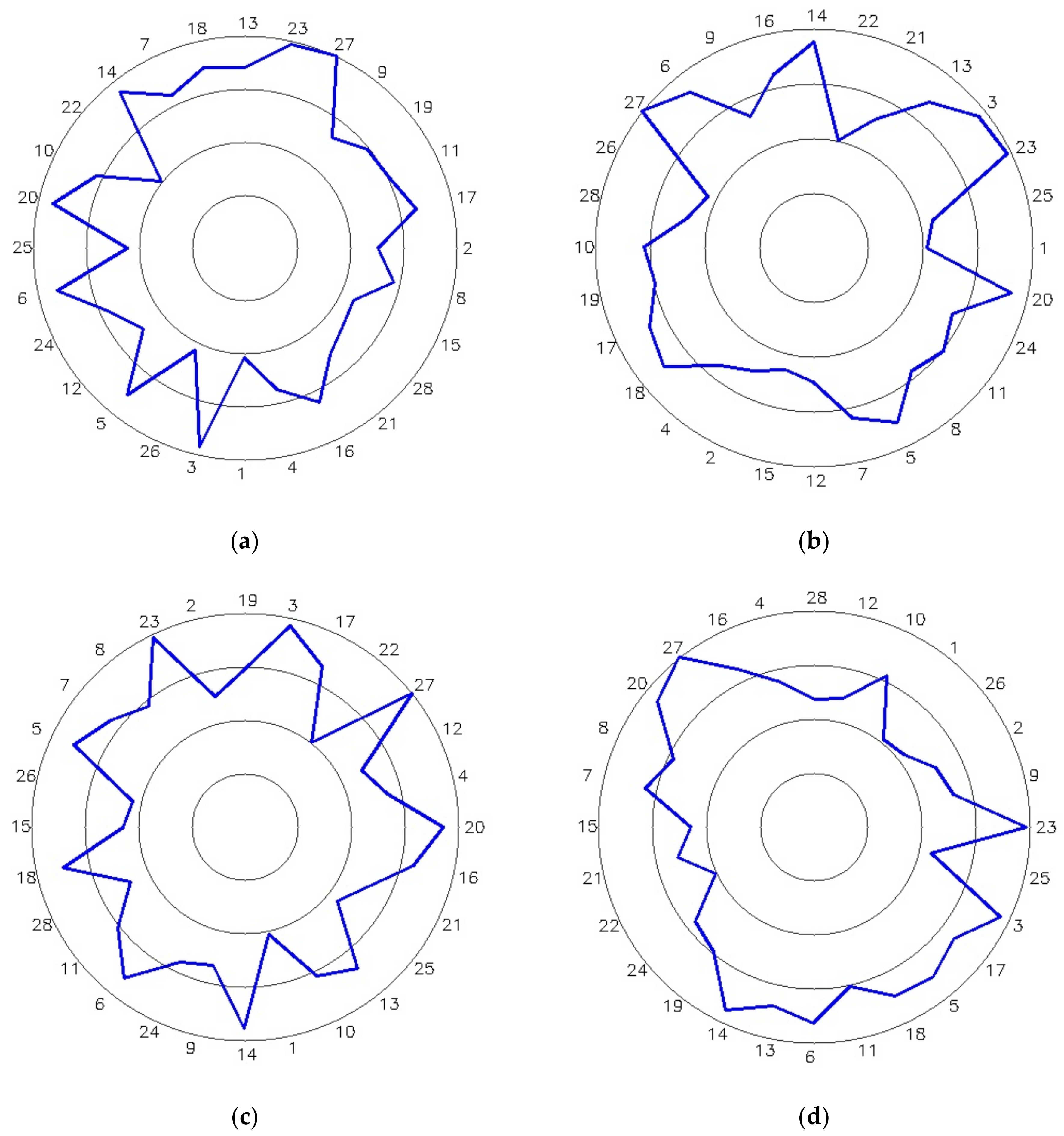
| First-stage blade | 28-2-4-22-23-5-11-17-27-3-24-21-18-12-14-13-20-8-25-31-6-30-10-9-16-29-32-1-26-19-15-7 | 0.0356 |
| Second-stage blade | 21-38-30-14-18-4-6-29-23-7-13-24-26-10-39-11-31-17-25-3-5-9-27-16-35-32-40-2-12-15-33-34-20-22-36-28-37-1-19-8 | 0.0158 |
| Third-stage blade | 17-27-30-15-9-46-12-21-45-7-4-25-5-2-36-10-42-28-29-11-31-20-3-39-44-35-32-14-19-38-41-6-43-13-26-22-33-18-40-34-23-37-1-24-16-8 | 0.0239 |
| Fourth-stage blade | 8-26-36-6-4-9-49-46-52-14-2-37-44-10-29-45-38-21-41-40-25-39-34-16-20-1-18-33-51-15-23-22-31-17-42-43-32-28-19-13-3-50-12-11-47-27-5-30-7-48-24-35 | 0.0210 |
| Fifth-stage blade | 45-49-50-32-10-41-25-22-18-37-29-35-38-42-44-28-19-17-2-47-16-48-4-39-53-7-3-21-14-9-43-5-30-8-36-40-1-34-54-23-46-33-52-51-6-27-24-12-31-11-26-55-20-15-13-56 | 0.0095 |
| Before Optimization | After Optimization | ||
|---|---|---|---|
| Input | Remaining unbalance force of the first-stage blade | 0.0356 | 0.0356 |
| Remaining unbalance force of the second-stage blade | 0.0158 | 0.0158 | |
| Remaining unbalance force of the third-stage blade | 0.0239 | 0.0239 | |
| Remaining unbalance force of the fourth-stage blade | 0.0210 | 0.0210 | |
| Remaining unbalance force of the fifth-stage blade | 0.0095 | 0.0095 | |
| Output | Overall residual unbalance force | 0.1058 | 0.0167 |
| Overall residual unbalance moment | 0.6348 | 0.0124 | |
| Installation phase angle | 0/0/0/0/0 | 247/92/261/0/115 | |
Disclaimer/Publisher’s Note: The statements, opinions and data contained in all publications are solely those of the individual author(s) and contributor(s) and not of MDPI and/or the editor(s). MDPI and/or the editor(s) disclaim responsibility for any injury to people or property resulting from any ideas, methods, instructions or products referred to in the content. |
© 2022 by the authors. Licensee MDPI, Basel, Switzerland. This article is an open access article distributed under the terms and conditions of the Creative Commons Attribution (CC BY) license (https://creativecommons.org/licenses/by/4.0/).
Share and Cite
Zhang, B.; Lu, H.; Liu, S.; Yang, Y.; Sang, D. Aero-Engine Rotor Assembly Process Optimization Based on Improved Harris Hawk Algorithm. Aerospace 2023, 10, 28. https://doi.org/10.3390/aerospace10010028
Zhang B, Lu H, Liu S, Yang Y, Sang D. Aero-Engine Rotor Assembly Process Optimization Based on Improved Harris Hawk Algorithm. Aerospace. 2023; 10(1):28. https://doi.org/10.3390/aerospace10010028
Chicago/Turabian StyleZhang, Bin, Hongyi Lu, Shun Liu, Yucheng Yang, and Doudou Sang. 2023. "Aero-Engine Rotor Assembly Process Optimization Based on Improved Harris Hawk Algorithm" Aerospace 10, no. 1: 28. https://doi.org/10.3390/aerospace10010028