1. Introduction
This article concerns assisted tele-operation systems for nuclear decommissioning and the characterisation of nuclear environments. To bring focus, the development and experimental work is based on an illustrative, hydraulically actuated, dual-manipulator device [
1,
2,
3]. At present, direct tele-operation is standard in the nuclear industry and vision systems are rare, except for those used simply to allow for remote tele-operation [
4]. With constrained spaces and highly-contaminated facilities, fully autonomous solutions are unlikely to be considered safe or cost-effective in the near future. Nonetheless, with the advent of more efficient and robust embedded electronics and sensors, which can be deployed in nuclear environments, there is significant interest in the development of new semi-autonomous capabilities [
5]. This is being reflected by a range of both theoretical and, as for the present article, applied research with a nuclear decommissioning robotics context for example, References [
5,
6,
7,
8,
9].
Vision systems are widely used in robotics, in both tele-operated and autonomous systems. The ability to both see and understand the local environment opens many possibilities and technologies using computer vision, such as object identification and object tracking, which can allow automation of many tasks. Commonly, vision systems used with robotic manipulators involve cameras fixed in place to give multiple views of the workplace. This approach might not be practical for a mobile nuclear decommissioning system, as it would need people to enter the dangerous work environment and install cameras in precise locations. Hence, methods that involve cameras mounted to the mobile platform with manipulators are being investigated. A number of proposed methods involve multiple cameras, for example with one camera fixed to the body of the robot and one on the end-effector. This provides a better view of the work place and makes control simpler [
10]. Other methods involve the deployment of a single camera with the aid of mirrors, providing a panoramic view of the working environment [
11]; and the coordination between ground-based and aerial robots [
12,
13,
14]. One of the challenges in the autonomous operation of robots for decommissioning is the radiation and noisy environment of the nuclear sites, hence there is interest in robust methods such as sliding mode and event-triggering control [
15].
Kehoe et al. [
16] use object identification combined with pose estimation to allow a dual arm robot to pick up and organise household objects. The system is able to identify what the object is, then what pose it is oriented in, so that it can pick it up and place it in the right location. Many other research groups have carried out substantial work using vision systems with manipulators, with a particular focus on grasping and manipulating objects. As examples of recent research with a nuclear focus, Talha et al. [
6] and Rastegarpanah et al. [
7] investigate the current technology of tele-operated systems, with multiple buttons and joysticks and with multiple cameras providing different views of the workspace. These results confirm that current tele-operated methods are extremely challenging, especially for inexperienced users, and will not allow the complex tasks needed for nuclear decommissioning to be completed.
1.1. Challenges in a Nuclear Environment
A significant number of nuclear facilities around the world have reached the end of their useful life and hence are in the process of decommissioning. Unfortunately, cleaning up a nuclear power plant concerns radiative waste materials that are highly harmful and unsafe for humans to approach. Since the decommissioning process is inherently environmentally unfriendly and dangerous for plant workers, it is known that many decommissioning tasks can be accomplished with the use of robots [
17]. For a significant number of nuclear decommissioning tasks, tele-operation is usually preferred. However, a certain level of autonomy has proven useful in some circumstances, especially where more accuracy and efficiency is required. Sometimes these operations cannot be directly seen by the robot operator. Additionally, the motion required can be complex, making the task difficult for inexperienced operators using direct tele-operation [
18]. The most common uses of robots for nuclear decommissioning are dismantling operations and the handling of waste materials [
19].
In one recent nuclear industry example, a monocular vision system is used to control a manipulator to fasten bolts onto a sealing plate for a steam generator [
20]. The robot operates by having a camera locate bolts around the plate and subsequently moving to fasten these to a set torque value. However, the system is limited in that it only looks for hexagonal bolts on a specially designed, bespoke plate. In high risk environments, such nuclear or search and rescue, full autonomy is often not desirable due to potential risks and lack of trust in emerging unproven technology. It is recognised, however, that direct tele-operation is slow and requires the operator to have considerable training and experience to be effective. As a result, techniques that lie in-between the two extremes are increasingly looked at as a solution. A degree of autonomy is introduced to lower the operator work load but the operator remains in overall control [
5]. Marturi et al. [
9], for example, have investigated the benefit of adding a level of autonomy during manipulation tasks. Direct tele-operation is compared with a visual guided semi-autonomous system for a block stacking task. The semi-autonomous system performs better than direct tele-operation, improving task completion time, precision and repeatability.
Bruemmer et al. [
8] focus on a robot used for characterisation in nuclear environments and a mixed-initiative control scheme is developed to improve performance in comparison to direct tele-operation, by allowing the level of automation to shift, giving the operator or the robot more control. In this case, if communication is lost the robot can become more autonomous and carry on the operation, returning control to the operator when communication is restored. Other vision-assisted applications have been investigated by Sun et al. [
21] and Shaukat et al. [
22], which involve the use of cameras and specialised algorithms to detect and classify nuclear waste. This approach and other human-machine interface (HMI) studies are a prelude to relevant grasping or pipe cutting, such as the work presented in the present article. Kapoor et al. [
23] propose a system for human-machine interaction that uses tele-operation and automation in a complex environment in a nuclear facility. A similar framework that covers different levels of human-machine interaction at CERN was proposed by Di Castro et al. [
24]. The importance of robots that can be operated with assisting techniques have been proposed by Matteucci et al. [
25], who developed a hydraulically-powered clamping robot controlled from a control panel that allows manual, assisted and fully automated operation modes. Finally, De Geeter et al. [
26] state that the adoption of advanced tele-operated robots for real nuclear decommissioning applications depends on the reliability of both the hardware and the automation systems in use. Whilst the former has been studied thoroughly via many prototypes and commercial products, the latter remains an open challenge.
1.2. Operator Feedback and User Interface
To allow effective control, the operator needs to receive some form of feedback from the robot that is, so they know where it is and the state of the work environment. For example, with a robot entering a nuclear power station part way through a decommissioning task, the operator may not know exactly where they are going or what to expect, and so relies on the feedback from the robot to navigate safely. Likewise, if a robot is operating in close proximity to other robots or people, the operator needs to know what is happening around it to allow safe operation. The simplest way to achieve this is to mount a video camera to the front of the robot so that the user can see what is in front of the robot, however this can be a rather limiting approach. Humans do not purely rely on looking straight ahead to know what is going on around them, they rely on their other senses such as hearing and feeling for example, the temperature. Hence, to allow immersive and effective tele-operation, often more sensors are desirable. Feedback from these sensors needs to be given to the user in an effective and usable way, to allow these to be beneficial for the operation of the robot.
Sensing and measuring a significant amount of data for direct communication to the operator is not necessarily an effective approach. In fact, providing the user with all the raw data is not always helpful and can actually make the operation more difficult. Increased automation yields complex interactions with the user and a reduction in situational awareness [
27]. A suitable user interface makes a big difference to the usability of a robot manipulator. Hence, a screen full of text and numbers is harder to comprehend than images and graphical representations of data. When displaying images on a screen, a number of features must be taken into consideration for the design of the graphical user interface (GUI). For example, screen layout, use of colours, clarity of images and fonts used all need to be carefully selected for proper usability [
28]. When choosing colours there are standard conventions, such as green meaning go, red being stop or error, and yellow being a warning, which are intuitive even to inexperienced users. These colour conventions are used amongst many interfaces and are, therefore, already common to most users. Layout conventions are also common across many interfaces and this is a significant subject of research on its own.
There are several ways for providing feedback to the operator, most commonly including: displaying video or sound on a screen [
29]; playing audio, either by directly replaying the sounds recorded near the manipulator [
30] or by providing audio cues such as beeping if the manipulator is moving towards an object to avoid collision; and haptic feedback e.g vibrations through a joystick [
29]. Force-feedback provides operators with a complete haptic experience since it can stimulate the operator’s sense of touch through the haptic tool (typically a joystick). Haptic devices are useful in tele-operation applications where both distance and danger are present [
31]. Haptic feedback can be used at different levels, from the user wearing a device that provides force or vibrations, with glove fingers to mimic what a robot manipulator is touching [
32,
33], to simply providing vibrations through a controller [
8,
34]. With control that uses motion tracking, haptic feedback may be more difficult to deliver than traditional control methods such as joysticks, however it is still a valuable feedback method that greatly increases the sense of user immersion.
1.3. The Microsoft Kinect
In the present work, the Microsoft Kinect has been chosen for research and development purposes. The release of the Kinect, a low cost camera capable of depth sensing and generating 3D point cloud data, has helped to encourage research into gesture recognition and markerless motion tracking. The original Kinect worked by projecting a pattern of infrared dots. Using an infrared camera the deformation of the pattern was measured and used to establish a depth map. The technology, called
Light Coding, was developed by a company called PrimeSense, which has since been bought out by Apple. Each Kinect was calibrated during manufacturing by placing it at a set distance from a wall and using that known pattern of the infrared dots as a reference point [
35].
Much research using the Kinect focuses on its ability to track the user’s skeletal position. Research by NASA and others have used a Kinect to track a user’s hand position and then move a robot arm to mimic movement [
36]. Another example is the project by Wasielica et al. [
37], which takes the user’s skeletal position to control the joint positions of a small humanoid robot. The robot combines the data from the Kinect with self-balancing and collision avoidance algorithms, to mimic the user’s movements whilst staying upright and not having any of its limbs collide. The advantage of using the Kinect for motion tracking is that no physical markers or sensors are needed on the user. Therefore, the user’s motion is in no way restricted. In other motion tracking systems a user may need to strap an array of sensors to their body to allow tracking. As well as direct skeletal tracking, the Kinect can be used for gesture recognition, with certain gestures corresponding to actions from a robot. Other studies [
38,
39] use the Kinect to monitor hand gestures, in which the robot moves into pre-set orientations depending on the gesture, such as waving move a robot arm in the direction of the wave.
The Kinect can also be used for navigation of mobile robots in indoor environments. Benavidez et al. [
40] use a Kinect to allow navigation and object tracking for a mobile robot. Navigation and mapping of indoor environments using the depth sensor is demonstrated by Correa et al. [
41]. Here, the depth sensor detects walls and obstacles and the position of these is graphed as the mobile robot moves around the indoor environment, building up a map of the area. This approach generally works well indoors and, as the depth sensor uses infrared light, the Kinect can be used to navigate even in the dark. However, it would likely be unusable outdoors as the depth sensor is very sensitive to external light. Another way the Kinect can be used for robotics applications is to identify and track objects, for example by generating coordinates to move a manipulator towards. Siradjuddin et al. [
42] use a blob detection algorithm to separate an object from the background based upon its colour. The algorithm obtains the 3D position of the centre of that object and uses it to position the robotic end-effector.
1.4. Objectives and Organisation
The present article concerns an investigation into some of the concepts raised above, using a previously developed dual-manipulator robotic platform in a non-active laboratory environment [
1,
2,
3]. The aim is to develop semi-automatic control systems that reduce operator workload, speeding up task execution and reducing training time, whilst minimizing the introduction of additional sensors and other components. Due to limited sensor data availability in nuclear environments, a system for grasping generic objects could be unreliable. As a result, the approach is based on the concept of multiple subsystems for common tasks under one user interface: one subsystem for pipe cutting, one for pick and place operations, and so on. This aims to reduce the complexity of the problem, potentially leading to improved performance and reliability. Furthermore, cognitive workload is reduced by tailoring the information shown to the operator to one task at a time.
The article focuses on pipe cutting as an illustration of the generic approach, since this is a common repetitive task in nuclear decommissioning. A systems design approach has been used to identify the engineering requirements of the new system. Motivated by preliminary testing that highlighted limitations in the initial control performance, a recently developed approach for modelling and control of hydraulically actuated manipulators is discussed in
Section 2.2 and
Section 2.3. Here, a state-dependent parameter (SDP) control system is proposed, for improved resolved motion of the manipulators. In contrast to earlier research [
2], the SDP model is utilised to design an inverse dead-zone controller to achieve the desired joint angle set points despite the inherent nonlinearities in the system dynamics. However, robust and familiar ‘off-the-shelf’ algorithms have been used where feasible for all other aspects of the system, including the image processing and trajectory planning tasks, and these are implemented using readily available MATLAB functions. As a result, the article takes a somewhat descriptive rather than mathematical approach in
Section 3 and
Section 4, which report on the lessons learnt and recommendations for future research, and with citations to the literature for details of the relevant algorithms. Hence, the main contribution and novelty lies in the hardware/software framework developed, and in our investigations into the desired practical midpoint between a fully-automated system and a tele-operated approach. In contrast to recent conference articles that have used the same machine but concentrated on the low-level control problem or on coordination with drones [
12,
43,
44], the present work fully describes the specifications and programming approach of the new assisted tele-operation system for the first time. The output is a vision-based semi-autonomous object grasping system that allows both experienced and inexperienced users to operate the dual-manipulator robotic platform, with minimal training.
Section 2 introduces the hardware demonstrator and control algorithms, while
Section 3 describes the new user interface and assisted tele-operation approach. Some experimental results and discussion of the issues arising are presented in
Section 4, followed in
Section 5 by the conclusions.
2. Materials and Methods
The robotic system has two Hydrolek manipulators with 7 Degrees-Of-Freedom (DOF) each (including the gripper), connected via a bespoke back-plate to a BROKK–40 base unit, as shown in
Figure 1 and
Figure 2. The system provides a good range of movement and flexibility to perform tasks in a confined space. In principle, the end-effectors can be equipped with a variety of tools, such as percussive breakers, hydraulic crushing jaws, excavating buckets and concrete milling heads. Without tools, each arm has a weight of 45 kg and the lift capacity at full reach is 150 kg. The first five joints illustrated in
Figure 2 (i.e., the azimuth yaw, shoulder pitch, elbow pitch, forearm roll and wrist pitch joints) are fitted with potentiometer feedback sensors allowing the position of the end-effector to be determined during operation. The joints are actuated via hydraulic pistons, which are powered via an auxiliary output from the hydraulic pump in the BROKK base unit. The movement of the manipulators is driven by proportional solenoid operated spool valves that are controlled through a National Instruments Compact Field Point (CFP) controller and its analogue input and output modules. This is an industrial standard Programmable Automation Controller (PAC) offering programmable logic controller performance, whilst interfacing with a standard PC running the National Instruments LabVIEW software. The hydraulic pistons are controlled by seven pairs of control valves, where each pair has an input for both positive and negative flow.
The CFP is a stand alone device running a real-time operating system, allowing for the precise sampling rates needed for discrete-time control. The PC transmits information to the CFP controller via an Ethernet network connection. For tele-operation, a standard input device, such as a joystick, is also connected to the PC.
2.1. Manipulator Kinematics
The kinematic equations necessary to resolve the planned motion are briefly considered. In standard manner, forward kinematics determine the end-effector position (
X,
Y,
Z) relative to the manipulator origin, in Cartesian coordinates, given the angles of each joint in the manipulator. The vectors of the dimensions of each link of the Hydrolek manipulator are shown in
Table 1 and the rotation matrix for each joint are listed in
Table 2. Here, the rotation matrices define the direction and axis of rotation, for a given angle
θ. Joint 6 is the gripper rotation, which has no impact on the kinematics and, therefore, the associated rotation matrix is an identity matrix.
Due to the geometry of the manipulator, all the rotation matrices are elemental rotations, as they each only rotate about a single axis of the coordinate system. By starting at the shoulder joint (
n = 1) and working towards the end-effector, where
n represents the joint number, following the chain of translations (
Ln) multiplied by rotations (
Rn), the end-effector position
P for known joint angles is determined in the standard manner as follows,
here,
n = 1 … 6 represent the joints associated with the azimuth yaw, shoulder pitch, elbow pitch, forearm roll, wrist pitch and wrist rotation respectively. The inverse kinematics (IK) for the calculation of the joint angles required to reach a given end-effector position and orientation are based on a conventional Jacobian transpose method. Here, the Jacobian matrix of partial derivatives of the forward kinematics equation is an
m ×
n matrix, where
m is degrees of freedom used to position the end effector and
n is the number of joints [
45]. In the 6-DOF case, using the existing computation set-up for the experimental work, the average time for the IK algorithm to calculate the necessary joint angles is well within the system requirements. For example, with an euclidean position error tolerance of 2 mm on the IK algorithm, the mean run time is 0.016 s. Some points take significantly longer to determine. This is due to the positions being randomly generated. Therefore, sometimes there are very large changes between the current position and the target position. This is a worst case scenario and, under normal operating conditions, the arm would not be moving from one extreme to another.
Table 3 shows a comparison of mean run time and position error for different error tolerances. The final column shows the average position error if errors greater than 10 mm are removed. This does not remove many points, but does have an impact on the mean as the outliers tend to be a long way out.
The outliers arise primarily because of the randomly chosen starting points for these experiments, with the Jacobian method getting stuck when moving between certain points. However, in the practical situations considered in this article, such as following a trajectory to position for a pipe cut, these problems do not arise. In fact, by ignoring the outliers, it can be seen that the mean error is very close to the set tolerance. It is clear that the Jacobian Transpose method performs reasonably well, and that the algorithm is both fast and accurate enough to be used in real time applications, as needed here.
2.2. Robot Dynamics
In the simplest case, the voltages to the hydraulics, as required to achieve the desired joint angles, are determined using conventional industry Proportional-Integral-Derivative (PID) feedback control loops, tuned by trial and error experimentation. However, in comparison to a typical machine driven by electric motors, hydraulic actuators generally have higher loop gains, wider bandwidths and lightly-damped, nonlinear dynamics. For the robotic platform in the present study, these dynamics have been previously represented using physically-based (mechanistic) equations [
3,
46]. However, the present article instead focuses on the identification from data of a relatively straightforward State-Dependent Parameter (SDP) model form, which is used here directly for nonlinear control design. The parameters of SDP models are functionally dependent on measured variables, such as joint angles and velocities in the case of manipulators.
Identification methods for robotic systems include, for example, maximum likelihood and inverse dynamic identification model with least squares (IDIM-LS) [
47]. Refined Instrumental Variable (RIV) algorithms are also used, sometimes in combination with inverse dynamic [
48,
49] or SDP [
2] models. However, in contrast to earlier SDP research for the same device [
2], an improved model structure is identified here. This model implicitly provides estimates of the dead-zone and angular velocity saturation, as illustrated below. The discrete-time deterministic form of the general SDP model is,
with the SDP parameter vector defined as follows,
and
. Here
vk and
yk are the input voltage and output joint angle respectively, while
and
are
n and
m state dependent parameters that is, functions of a non-minimal state vector
(see worked example below). In the case of a hydraulic manipulator, the model is identified in three stages as follows:
Step 1. Open-loop step experiments using the manipulator suggest that a first order linear difference equation, that is,
provides an approximate representation of individual joints, with the time delay
τ depending on the sampling interval Δ
t.
Step 2. The values of
are not repeatable for experiments with different input magnitudes. However, SDP analysis of experimental data suggests that
n =
m = 1,
a1 = −1 is time invariant and
is a static nonlinear function [
43,
44].
Step 3. Finally,
is parameterized, here using exponential functions for the nonlinearity. To illustrate using the right hand side ‘shoulder’ joint, denoted
J2, with Δ
t = 0.01 s and
, RIV estimates
for step input experiments of varying magnitudes are shown in
Figure 3, demonstrating the clear state-dependency on the input.
The mechanistic interpretation of this model is straightforward: using Equation (
4) with
, yields
that is,
represents a smoothed estimate of the differenced sampled output and
provides an estimate of the angular velocity, with the latter facilitating an estimation of the dead-zone and velocity saturation limits. As a result, denoting
, the SDP model for
is,
with constraints
, where
and
are hardware limits and,
A numerical illustration for is that for are . To obtain these estimates, experimental data are compared with the model response and the mean sum of the least squares output errors are used as the objective function for fminsearch in MATLAB. Here, are curve coefficients; /s and /s provide minimum and maximum angular velocity saturation limits; and V to V is the dead-zone. These objective estimates compare closely with equivalent values obtained from extensive prior ad hoc experimental work. Similar SDP model forms are identified for each joint of both manipulators.
2.3. Robot Control
For control system design using the SDP model, the present study utilises a novel combined Proportional-Integral-Plus (PIP: [
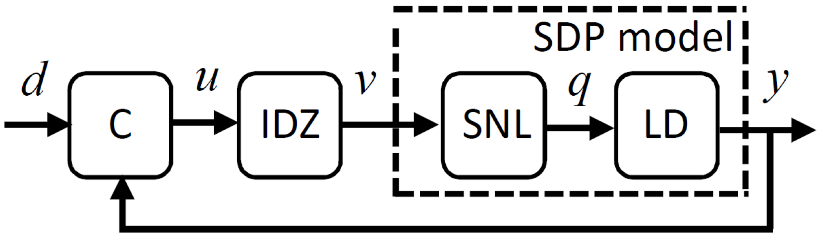
50]) and Inverse Dead-Zone (IDZ) approach.
Figure 4 shows the control system, in which
is the desired joint angle from the IK and trajectory planning algorithm,
is the PIP control input (see below),
is the voltage to the National Instruments CPF computer,
is the angular velocity and
is the joint angle. Selecting a control sampling rate
s as a compromise between satisfactory reaction times and a relatively low order control system,
Figure 5 shows the linearised relationships for
and
in the range (i)
to
and (ii)
to
in the negative and positive directions of movement, respectively. For
,
and
, selected since they yield an angular velocity
s
−1 in either direction, and it seems unlikely that faster movement would be desirable in practice. This approximation is the so called Static Non-Linear (SNL) element of
Figure 4 and is defined as follows (cf. Equation (
6)),
where
and
. Adapting from for example, Reference [
51], the IDZ control element of
Figure 4 is, therefore,
where
is a ‘chatter’ coefficient. Equation (
8) aim to cancel the static nonlinearity and allow use of linear control methods. For
with
,
and hence, using standard methods [
50], based on the model (
4) with
, the PIP control algorithm takes the following incremental form,
with constraints
, in which
and
are introduced to avoid potential integral-wind up problems, and the control gains
,
,
and
are determined by for example, conventional Linear Quadratic (LQ) optimisation.
Figure 4 illustrates the new control system, in which the linear Controller (C) and IDZ element of the controller are given by Equations (
8) and (
9), respectively. The dashed box in
Figure 4 represents the identified SDP model, which consists of the SNL element (
7) and the Linear Dynamics (LD) (
5). This new approach integrates input signal calibration, system identification and nonlinear control design, allowing for straightforward recalibration when the dynamic characteristics have changed or the actuators have deteriorated due to age, which can be important in the present application.
3. User Interface and Assisted Tele-Operation
In a nuclear environment where radiation can damage sensors and electronics, there are broadly two different directions of research. The first is to design for redundancy that is, having multiple sensors that can act as backups. This approach is not necessarily cost effective and, since all the sensors are in the same location, they will likely wear out at an equal rate. The second option is to minimise the number of sensors making them easily replaceable. In the present work, a single camera that can be easily be replaced is used. However, complementary research by the authors and others that augments the main camera with additional (e.g., mobile) cameras is on-going [
12].
For demonstration and experimental purposes, the GUI shown in
Figure 6 was developed for MATLAB using GUIDE (GUI Development Environment), since this facilitates straightforward refinement as the research progresses. GUIDE allows the appearance of the interface to be set graphically, for example positioning the buttons and graphical displays for the camera video feed. Once the interface layout is set, MATLAB creates the necessary code, which is used as the framework for developing the control programs.
The Microsoft Kinect camera requires several elements in order to work effectively. In the first instance, the Kinect for Windows SDK allows the Kinect to interface with the PC. In addition, the image acquisition (IMAQ) toolbox for MATLAB and the Kinect for Windows Sensor Support Package are required. The latter allows MATLAB to recognise that an existing video input device is the Kinect. The IMAQ toolbox provides the functions for initialising the Kinect using the data produced by the RGB and depth sensor, allowing it to be used with standard MATLAB functions.
3.1. Stage 1: Positioning
The platform is first positioned in the target work area to ensure the target object is visible in live video feed. Initially, while the operator moves the mobile platform to the target work area, the Kinect is providing live colour video at all times, displayed on the developed GUI to allow the operator to see where they are going. To position the platform, the operator has control of the tracks on the base, as well as the BROKK boom arm, which is used to position the shoulder plate of the dual manipulators to the required height for example, to reach forward over an obstacle. The Kinect is fixed in place on the plate between the two hydraulic manipulators, so positioning in this way does not impact on the later coordinate system transforms between the camera and the manipulators.
To bring focus to the description of the proposed assisted tele-operation approach, the following subsections provide an overview of the steps involved when using the interface to position the manipulators for a standard pipe cutting task.
3.2. Stage 2: Image Capture and Edge Detection
Stage 2 is activated when the operator clicks the
takesnapshot button that is, to capture a still image from live video and to carry out edge detection. Once the platform is in the desired position, the operator presses this button on the interface, as shown in
Figure 6. This takes a screen-shot of the live video, performs some preliminary processing and presents an edge-detected image to the operator. Using a screenshot of the live video proves satisfactory in this application, since the environment is not highly dynamic (i.e., target objects are unlikely to be moving) and processing a screenshot rather than a video saves significant computational power. In addition, the live video is still shown to the operator to maintain situational awareness.
The screenshot is captured by taking a single frame of the live video using the
getsnapshot function of the IMAQ toolbox. The live colour video continues being shown on screen, to provide constant visual feedback to the operator. The captured screenshot goes through several stages of editing and manipulation before being displayed to the operator alongside the live video. The image is first processed to show only the edges of the objects in view, and has objects out of reach removed. This approach yields a simplified view of the workspace, showing separate objects each enclosed by a continuous solid trace. An example image is shown in
Figure 7, in which a single pipe is enclosed by a continuous solid line. In this example, the pipe extends out of view, and the edges of the camera view are treated as object edges.
Once the user presses the button to take a screen-shot, a number of steps are carried out in the background that lead to the final edge-detected image. Initially, the RGB and depth images are aligned using the
alignColorToDepth function from the IMAQ toolbox. This is required because of the offset between the sensors on the Kinect, which creates a mirror image of the scene. The image is subsequently converted to greyscale (as required for the later edge detection algorithm) using the
rgb2gray function of the IMAQ toolbox. To reduce the size of the image and computational complexity, as well as to only present useful information to the user, all areas that are either out of reach of the system or that have no depth data available, are removed. This is achieved by creating a binary mask of the image with each pixel set to either 1 if there is depth data and it is within reach or to 0 if there is no depth data or the depth value is out of reach. The binary mask is subsequently multiplied element-wise with the now greyscale image to keep the parts within reach, and to remove the parts out of reach. This leaves the image only containing reachable areas, as illustrated by
Figure 7b, with out of reach areas being shown black. Depth data may not exist for a number of reasons, including surfaces not reflecting structured infra-red light back to the sensor, scattering of the light so that it cannot be returned to the sensor or objects being shadowed from the sensor light. If the object the operator intends to grasp is not shown, they can reposition the manipulator system and try again.
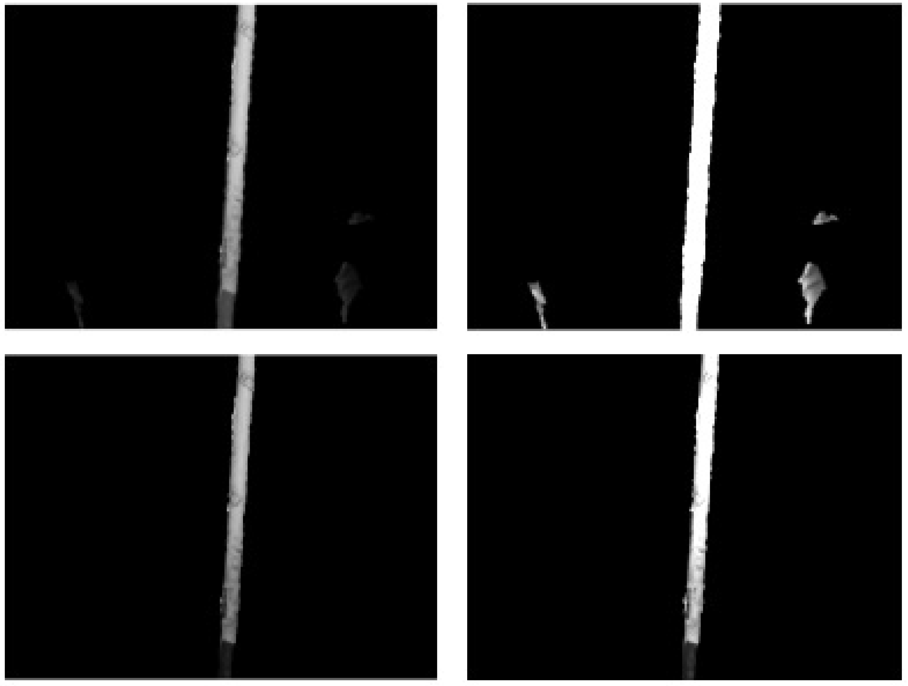
The next stage involves the creation of three copies of the image, each set to a different contrast level using the
imadjust function, as demonstrated in
Figure 8. Sliders on the GUI allow the operator to adjust the contrast levels. Here, for two of the images, the inputs to the
imadjust function are the values from the sliders, and for the third image pre-set values are used. These three images, together with the original, are forwarded to the edge detection algorithm. Noting that the working environment of the manipulator system is likely to be poorly lit, this approach lessens the impact of shadows and highlights, and is found to capture more detail in practice.
Figure 9 illustrates such an improvement in the captured detail, allowing edges that would otherwise be missed to be captured. This approach was inspired by bracketing techniques used in photography, where multiple shots of a subject are taken with different camera settings and subsequently combined.
3.3. Stage 3: Operator Image Adjustment
The four images are passed through a Canny edge detection algorithm [
52] implemented in MATLAB using the
edge function with
canny set as the second input argument (the first input argument being the image name). The Canny algorithm is a widely used for image processing in many application areas [
53,
54]. This algorithm has been shown to perform better than other edge detection algorithms in most situations, albeit at the cost of being relatively computationally expensive [
55]. However, reliable detection of solid edges is an essential requirement of the proposed system, hence the Canny algorithm was chosen. The Canny algorithm allows a sensitivity threshold to be set that is, to alter how strong the edge has to be, in order to be detected. Hence, a third slider on the developed GUI allows the operator to adjust this sensitivity threshold, allowing for on-line adjustments to which edges are detected. This is particularly useful if there are markings on the target objects which are being detected. By increasing the sensitivity threshold, these markings can be ignored so that only the edges of the object are seen.
During stage 3, the operator ensures that the target object is visible in the edge image, and uses sliders on the interface to adjust the edge image if necessary. The four edge-detected images are combined to yield one edge-detected image that contains more detail than if just the original image had been used, as illustrated in
Figure 9. Due to the edge images being binary images, combining them is a simple case of adding the images together. Finally, the combined edge-detected image has the lines dilated in order make the displayed image clearer to the operator. Dilating the lines consists of two steps, as follows.
First the strel function is used to set a morphological structuring element for dilation. The structure used in this case is a line 2 pixels long, so each pixel is checked and if its neighbour is set to 1, representing a line, the pixel being checked is also set to 1. This is performed in both the horizontal and vertical directions. The motivation here is to close small gaps in the detected edge and, by keeping the structuring element as a line only 2 pixels long, false edges are not created, while small holes in the edge image are filled in. The choice of structuring element shape and size was chosen through trial and error experimentation, looking at the output of the edge image. The strel function can work with a variety of shapes including discs and squares, and the size of that element is set by the user. Pipes tend to have straight edges, hence it is found that the line option works well, and performing this step in both horizontal and vertical orientations allows pipes of any orientation to be found.
In the second step, the edges are dilated using the
imdilate function, with the two (horizontal and vertical)
strel function outputs used as inputs to the dilation function. This is to make the edges clearer when displayed to the operator, rather than having very thin lines, and also because the edges detected on the 4 images with different contrast levels do not perfectly overlap, as shown in
Figure 9, hence dilating the edges results in one solid edge. Note that the three sliders on the GUI, to control the image high and low contrast and the edge-detection sensitivity, update the displayed edge detected image in real-time, with a change in slider value triggering the image manipulation function to restart. This allows the operator to adjust the image, potentially removing superfluous edges or filling in missing edges, without having to reposition the system.
3.4. Stage 4: Operator Target Selection
Stage 4 involves selecting the target object in the edge image. Once the edge-detected image is showing the object that the user may want to grasp as an enclosed area, the operator selects the object by clicking anywhere within this area using the mouse. The image is immediately updated to show only the selected area. An image showing the colour screenshot, with the selected object highlighted is simultaneously shown, providing visual confirmation to the operator that the correct object has been selected. The position that the operator clicked on is found as an
x and
y pixel coordinate, using the MATLAB
get function, which returns the
CurrentPoint of the cursor. This function is triggered by the mouse click and returns the cursor position. These coordinates are rounded to the nearest integer since the
get function returns a level of accuracy not needed by the GUI. With these coordinates available, the next step is to check that the operator clicked within the edge image on the GUI, and not anywhere else. Assuming they have clicked on the edge image, the area enclosing the clicked point is filled to create a solid on-screen object. This is achieved with the
imfill function, which takes the edge image (with dilated edges) and the mouse click coordinates as inputs, and acts in a similar manner to the way that a flood fill function operates in image processing software. The image with the filled in area is stored as a new image, and has the edge image subtracted from it, to leave just the selected object as a solid block. At this stage, there will usually be a solid rectangle left, since that is what sections of pipe look like after passing through an edge detection algorithm, as can be seen in
Figure 9.
With the object selected and separated from the rest of the image, its perimeter is found. This is laid over the original colour screenshot and shown to the operator as a validation step that is, to check that they have selected the correct object. The bwperim function is used to find the perimeter of objects in the binary image. The perimeter is subsequently further dilated, using a similar approach to that described in Stage 3. This is to ensure that the object perimeter is clear when shown on the colour image. To combine the perimeter shape with the colour image, the colour image is first split into its separate RGB channels, yielding three versions of the image. The pixels of the colour image that correspond to the perimeter are changed to red that is, only one of the new images needs modifying. This is achieved in MATLAB using image(perimeter) = 255, where image is the name of the red channel separated from the original image and perimeter is the binary file of the object perimeter. Combining the three separated channels yields a new single image that is almost the same as the original colour image, except that the pixels corresponding to the selected object perimeter have been changed to red. Finally, this image is displayed on the GUI so the operator can confirm they have selected the correct object before continuing.
3.5. Stage 5: Grasp and Cut Location
The user proceeds to click on the point they determine the manipulator should grasp the object, a pipe in the present context and, with a second mouse click, the location they wish the cutting operation to start from. The coordinates of the mouse clicks are found in the same way as already described for Stage 4. For stage 5, however, the selected positions for grasp and cut are automatically snapped to the major axis of the object that is, the centre line of the pipe. The centre line and orientation are determined using the
regionprops function in the MATLAB image processing toolbox, which can calculate a number of properties about an enclosed region. In this case,
regionprops is used to determine the centre coordinates, the orientation and the major axis length. The centre line of the pipe is determined with these three characteristics that is, using Equation (
10) to find the coordinates of the two ends of the centre line, (
,
) and (
,
).
here (
,
) are the centre coordinates,
length is the major axis length and
is the major axis orientation. In other words, the centreline is identified by creating a linear vector of points between the end coordinates. Note that the operator-selected points are snapped to the corresponding points on the centre line, with the smallest absolute difference between the selected point and centreline point. To achieve this, the orientation is first considered, as this will determine if the closest point is along the horizontal or vertical axis. If the orientation is under 45° from the horizontal, the translation will be along the
X-axis, so the absolute difference between the selected
X coordinate and each
X coordinate element in the vector describing the centre line is found. The element in this array with the smallest absolute difference is identified. If the orientation is over 45° the same process happens but with the
Y coordinates instead of the
X coordinates. Hence, the operator does not need to accurately click on the centre line of the pipe, making the task easier. Furthermore, the grasp target is centred on the major axis of the pipe, so that the gripper fingers will not hit the pipe even if the user had inadvertently clicked on one edge of the pipe.
The start and end positions for the cutting operation are determined such that the path of the cutter is perpendicular to the major axis of the pipe, at the position the operator selected. The start and end-points also take a pre-set distance from the edge of the pipe, by finding the width using the minor axis length property of the
regionprops function and adding a set value to either side. This is to allow any width of pipe to be cut, and ensures clearance for the cutting tool before and after the cut. The coordinates for the cut start and end positions are found in a similar way to that shown by Equation (
10), but here using the orientation plus 90° to ensure the manipulator is perpendicular, and the
length value is the minor axis length plus the preset offset. By calculating the grasp location and cutting path based on the major axis of the selected pipe, any orientation of pipe can be addressed, such that the system is able to cut pipes that are horizontal, vertical or at any angle in-between. Since depth data are available at both the selected points, the pipe does not even have to be in one plane, whilst the grasp and cut points could be at different distances. To reduce the possibility of collisions between the end-effector and the pipe being grasped, and to help position the gripper in the target orientation, the end-effector first moves to a position directly in front of the target grasp position; subsequently, when it has reached a set error tolerance for that position, it is moved into the final grasp position.
3.6. Stage 6: End-Effector Positioning
Stage 6 is activated when the operator presses Return. The manipulators will move to the given positions carrying out the grasp and cut operation. At this stage there are four goal positions that is, the cutting operation start and end positions, the initial position directly in front of the grasp location and the final grasp location. In the description above, these points have all been addressed as pixel coordinates that is, the pixels that the user clicked and the corresponding depth values. To be used as input arguments to the IK algorithm, these are necessarily converted into the manipulator coordinate system. Keeping everything in pixel coordinates until this stage allows the system to be modular. The vision processing and user interface is one module, and the kinematics algorithm is a separate module. This allows the user interface to be applied to different manipulator systems, simply by changing the kinematics algorithm.
To convert from pixel coordinates to the manipulator coordinate system, a trigonometric approach is taken. The number of pixels in the image from the Kinect is known (640 × 480) and the field of view of the camera is 57° horizontal and 43° vertical, hence it is a straightforward matter to determine the degrees per pixel that is, 0.089° for both horizontal and vertical. By shifting the origin of the camera image from the upper left corner (default position) to the centre of the image, the angle between the camera centre and the user-selected point can be determined. The transformation from the original pixel coordinate system, to shifting the origin to the centre of the image is straightforwardly determined as follows: and , where x and y are the pixel values where the user originally clicked. This formulation ensures that points to the right and above the centre are positive and points to the left and below the centre are negative, which yields the same positive and negative directions as the manipulator coordinate system. Using these coordinates and the depth data, the real world coordinates relative to the camera origin are and , where Z is the depth value and 0.089 is the degrees per pixel value determined previously.
For the Kinect, points on a plane parallel to the sensor all have the same depth value (rather than the straight line distance from the point to the sensor) and this defines the trigonometric identity to use. At this stage of the process, the coordinates are relative to the camera centre. Hence, a translation is required to convert these into a usable form for manipulator movement, namely a translation from the camera origin to the manipulator system origin, which is the shoulder of the right side manipulator. The transformation from the user-selected pixel to the manipulator coordinate input is:
where
x and
y are the pixels the user clicked on, while the arrays
are the manipulator target coordinates, determined for each of the four goal positions. The Jacobian transpose-based IK solver is utilised to find the associated target joint angles. These joint angles represent set points for the feedback control algorithms that control the hydraulic actuators. With regard to practical implementation, the user interface and all the calculations up to this point have been coded using MATLAB. However, the present hardware framework requires control signals from LabVIEW. Hence, the joint angles are sent via a TCP/IP link to LabVIEW, in which they are used as set points for the joint angle feedback control system, also implemented in LabVIEW, to generate a voltage signal to send to the controller of the hydraulic valves. This architecture allows the GUI to be on one computer, and the controllers to be on a separate machine, further facilitating both remote operation and modular development.
4. Results and Discussion
Comprehensive evaluation tests in the laboratory show that the assisted tele-operation system works effectively. These tests demonstrate that an operator can see and select a pipe using the GUI, and the manipulator successfully grasps and moves as though cutting through it (pre-empting the use of appropriate cutting tools in future research). Such tests have been repeated from various random manipulator starting positions, for a wide range of pipe orientations and background object scenarios, and with successful grasping achieved each time.
Although not the main focus of the present article, the new control system described in
Section 2.2 and
Section 2.3 also yields promising results. With regard to the model performance, an illustrative set of nine evaluation experiments yields a mean absolute error between the measured angle and the SDP model output (using Equations (
5) and (
6) for
) that is reduced by one third in comparison to the conventional linearised model on which the original PID control algorithms were developed. Moreover, with regard to control system performance, when applied to all the joints of the manipulators, for example during the pipe grasping experiments, the PIP-IDZ control algorithms yield an average Euclidean norm (representing the overall control performance based on the end-effector position) that is 45% lower than the benchmark PID approach. Further research is required to build on these results and to compare PIP-IDZ control with other nonlinear algorithms.
Here, it should be noted that these initial tests were completed by the second author of the present article, who is experienced at use of the system.
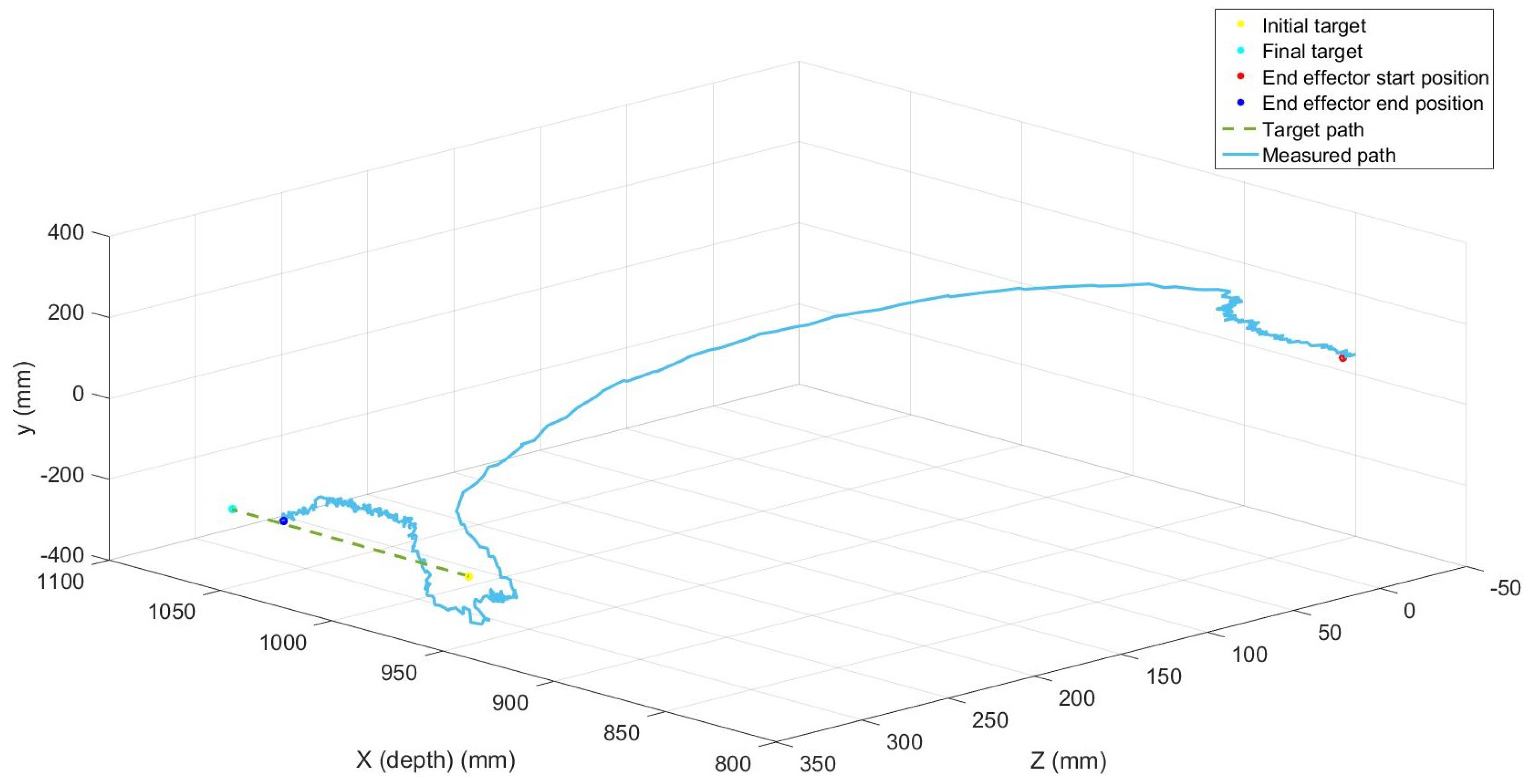
Figure 10 shows an example for the right hand side manipulator moving to a target grasp location. Before proceeding to the final pipe grasp, the final end-effector position had a Euclidian distance error of 17.1 mm from the target and took 5.4 s to complete the movement. This is within acceptable tolerances for grasping; however, for efficient cutting improved control system accuracy would be needed. When a cutting tool is moving between two points, the errors stack up and could become significant, especially if a mechanical cutting tool such as a circular saw is to be used. In such a case, small errors could cause a planned horizontal trajectory to be non horizontal, stressing the cutting tool and potentially causing a breakage. This issue motivates further research into the low level control problem to ensure more accurate positioning of hydraulic manipulators.
Since the new system actuates all the joints in parallel, significantly faster moving times are possible, compared to conventional tele-operation via joystick control. The latter approach requires different buttons to be pressed in various configurations to control each joint. By contrast, the new method considered here, replaces these complex movements using joysticks to control each joint independently, with just four mouse clicks to complete a pipe grasp and cut operation. To evaluate this attribute of the proposed system, preliminary tests have been carried out with both experienced and inexperienced operators, each performing grasps using both the traditional joystick direct tele-operation and the vision based semi-autonomous system developed in this article.
Table 4 shows 12 such experiments. Each experiment starts with the manipulators and pipe in the same position. First the operator uses the joystick method to grasp the pipe. This is repeated three times. The same user subsequently operates the new vision system, again three times. These tests are repeated for both experienced and inexperienced operators. The inexperienced user had never used the system before but received 15 min training and practice with the joysticks. The experienced operator was already familiar with the joystick control method.
The times taken to complete the task are listed in
Table 4, which shows that the new system yields considerably faster performance for the grasping task, for both operators. It is interesting to note that the execution time is only a few seconds longer for the inexperienced user when using the vision system, suggesting that it is relatively straightforward to learn how to use the new system. It should be stressed that these tests are limited in scope. Although representative of other similar informal tests by the authors, the figures given in
Table 4 are limited to two users and one type of task. To provide a more thorough comparison, clearly more users and more detailed test scenarios should be investigated. In further research, for example under the scope of the UK National Centre for Nuclear Robotics, the present authors will evaluate the present system systematically, and will compare different methods for assisted tele-operation that are being developed by the collaborating partners. One approach will be to use the NASA task load index (NASA TLX) assessment. This assessment requires users to subjectively rate a task on six different areas and is used widely in human factors research. The approach was used by Marturi et al. [
9], for example, who investigated the effect of adding a level of autonomy to direct tele-operation systems, in particular for point to point movement and for a block stacking task. In addition, the system is being used to develop and evaluate new algorithms for inverse kinematics, trajectory planning, control and cooperation with other mobile robots, and these results will be reported in future articles.
References [
56,
57] are also important in this context. Husain et al. [
56] use depth data to segment an object from the background and track it moving within the workspace. The manipulator moves to the target object until it can grasp it. For the system investigated by Kent et al. [
57], a user clicks on a desired grasp position on screen and is subsequently presented with grasp positions to select from. It was shown that the point and click approach performed significantly better than the original user interface. A major difference, however, is that Kent et al. [
57] used a single fixed manipulator, with two 3D cameras, one mounted in front of the workspace and one above, giving plenty of information about the workspace. By contrast, the research here uses dual manipulators on a mobile platform, with a single 3D camera mounted onto the robot itself. Nonetheless, to summarise, the results presented above appear to support the conclusions of other recent studies by presaging the likely benefits of assisted tele-operation. They provide an indication of the potential for improved performance and reduced requirements for operator training, when using assisted tele-operation, in comparison to the directly tele-operated system presently used on nuclear sites.
Finally, it is important to note that the concepts reported here will face additional challenges in a radioactive environment. Although the hydraulic components of the dual-arm manipulator might not be prone to immediate damage, it is well understood that electronic components, particularly semiconductors, are vulnerable to radiation. Hence, modern electronic components in systems such as the Kinect tend to fail under radiation [
58]. Shielding of electronic components reduces the effects of radiation [
59], whilst other devices such as microcontrollers have shown a degree of tolerance [
60]. Specifically for gamma radiation, high-density materials such as lead (
Pb) are typically used for shielding. However, in highly radioactive environments (>100 Gy/h), the positive effects of shielding on electronics systems are not very significant, even with very thick layers of lead. It is known that the bigger transistor sizes found in vintage electronics are more radiation tolerant than modern electronics systems with small transistor sizes. Therefore, the use of semiconductor devices made with earlier technologies or new manufacturing techniques for Application Specific Integrated Circuits (ASIC), could provide a strategy for the future deployment of systems in nuclear sites [
61].
Nagatani et al. [
58] report on certain electronic systems surviving a radiation test at more than 200 Gy/h in a 5-h experiment. However, sites where radiation levels reach 100 Gy/h or more are considered disaster areas, where tasks such as precise cutting are not necessary. The vision-assisted tele-operation reported in the present article would be expected to function as intended for at least 8 h in environments with comparatively low radiation levels (<10 Gy/h). Such issues are the subject of on–going research. For example, Wang et al. [
62] have carried out radiation experiments for a number of high-definition cameras with Cobalt-60 gamma rays. The commercial-off-the-shelf devices still worked at 10 Gy/h during an 8-h experiment.
5. Conclusions and Future Work
The article has reported on the development of a vision-based, semi-automatic object grasping system for a hydraulically actuated, dual-manipulator nuclear decommissioning robot. The proposed system is sympathetic to current industry trends to improve on direct tele-operation methods whilst keeping an operator in the loop. Since full autonomy might be undesirable in the nuclear industry for certain types of decommissioning task, it is important to investigate a range of automation levels. The broad concept behind the new system is to have separate modules for different tasks; for instance, one for pipe cutting and one for pick and place operations. The level of autonomy is dependent on the selected task. This would simplify the system and allow the interface and level of autonomy to be tailored for each task. The focus in this article was pipe grasping and cutting, since this has been identified as an example of a common repetitive task in decommissioning. This is a highly skilled job requiring experienced operators, while being time consuming. However, the concepts investigated in this article are also applicable to future decommissioning robots engaged on other tasks. The article has also considered a new approach to hydraulic manipulator control based on SDP models and this is similarly applicable to other robots and types of control problem. This method integrates input signal calibration, system identification and nonlinear control design, allowing for straightforward automatic recalibration when the dynamic characteristics have changed over time, for example due to a deterioration in performance when operating in challenging environments.
The developed assisted tele-operation system presents a straightforward GUI to the operator, who with just four mouse clicks can select target positions for each manipulator to perform a pipe grasp and cut action. Throughout the process, the user can view the live colour video and terminate manipulator movements at any time. The system was tested on a full-scale hardware system in a laboratory environment. It is shown to work successfully, outperforming the currently used joystick-based tele-operation approach when tested for an experienced operator and for preliminary tests with an inexperienced operator. The system keeps the user in control of the overall system behaviour but, significantly, reduces user workload and operation time. Further research is required to support these conclusions, including additional experiments with more users and particularly in relation to attaching suitable cutters and working with real pipes and other objects. Future experiments include extending the system to place the cut pipe in a target location and using both manipulators to grasp the same object in order to move particularly heavy objects.
To date, the developed system has been evaluated in non-radiological environments. Whilst the hydraulic actuation system is unlikely to be significantly impaired by the presence of raised radiological fluence, the tolerance of the vision system requires further research. For example, although low-cost Kinect cameras have been utilised for research and development purposes, these can be damaged by high levels of radiological flux. Fortunately, numerous other radiation hardened cameras are becoming available off-the-shelf. Furthermore, significance research effort aims to improve the hardness of traditional components [
63]. Finally, wrist force/torque sensing and advanced master-slave controllers can potentially further improve the developed assisted tele-operation system and this is the subject of on-going research by the present authors. Again, however, the semiconductor devices involved in any force-feedback electronics architecture will require improved radiation hardness for deployment on nuclear sites.


