Design and Implementation of a Dual-Axis Tilting Quadcopter


Abstract
:
1. Introduction
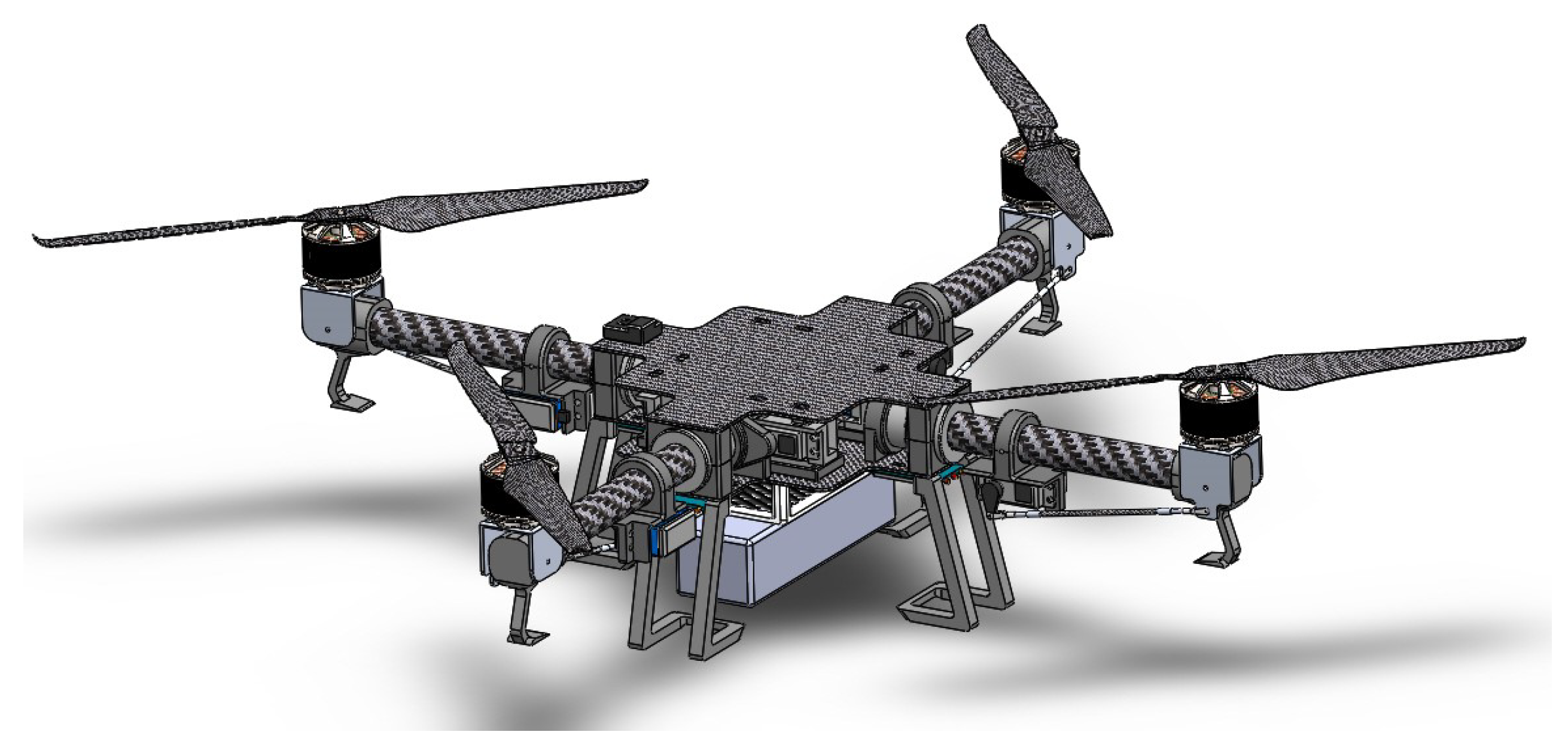
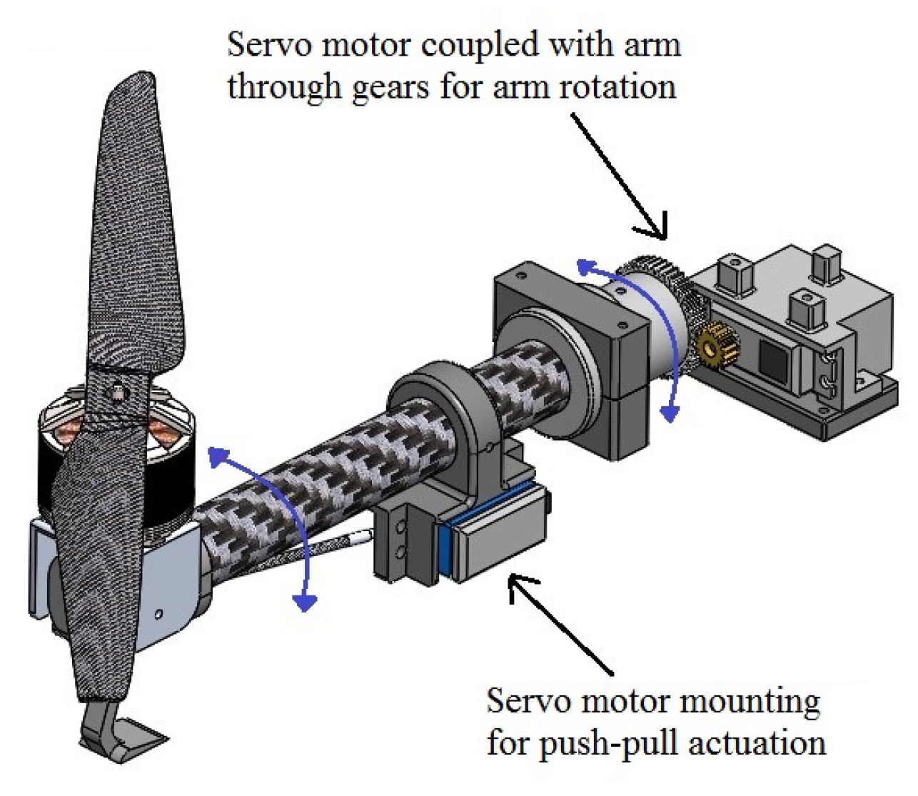
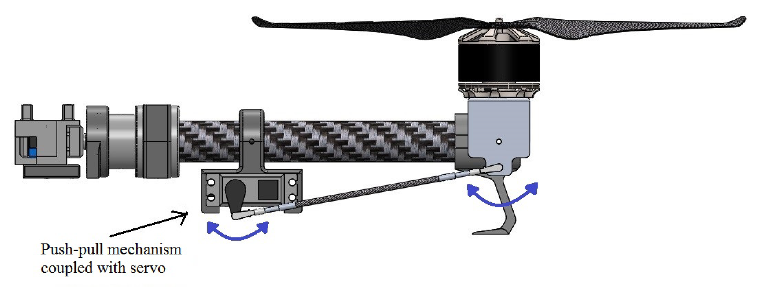
2. Design Approach
3. Modeling and Simulation of Over-Actuated Quadcopter
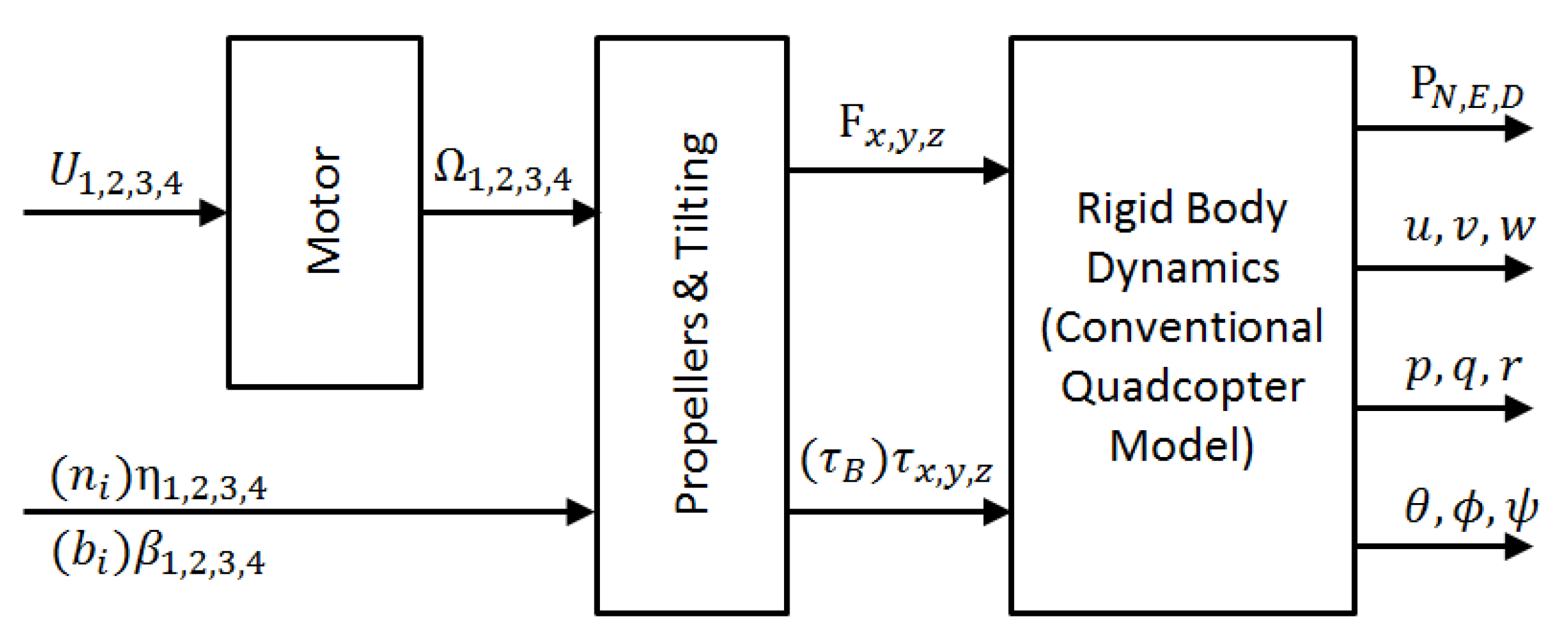
3.1. Modeling
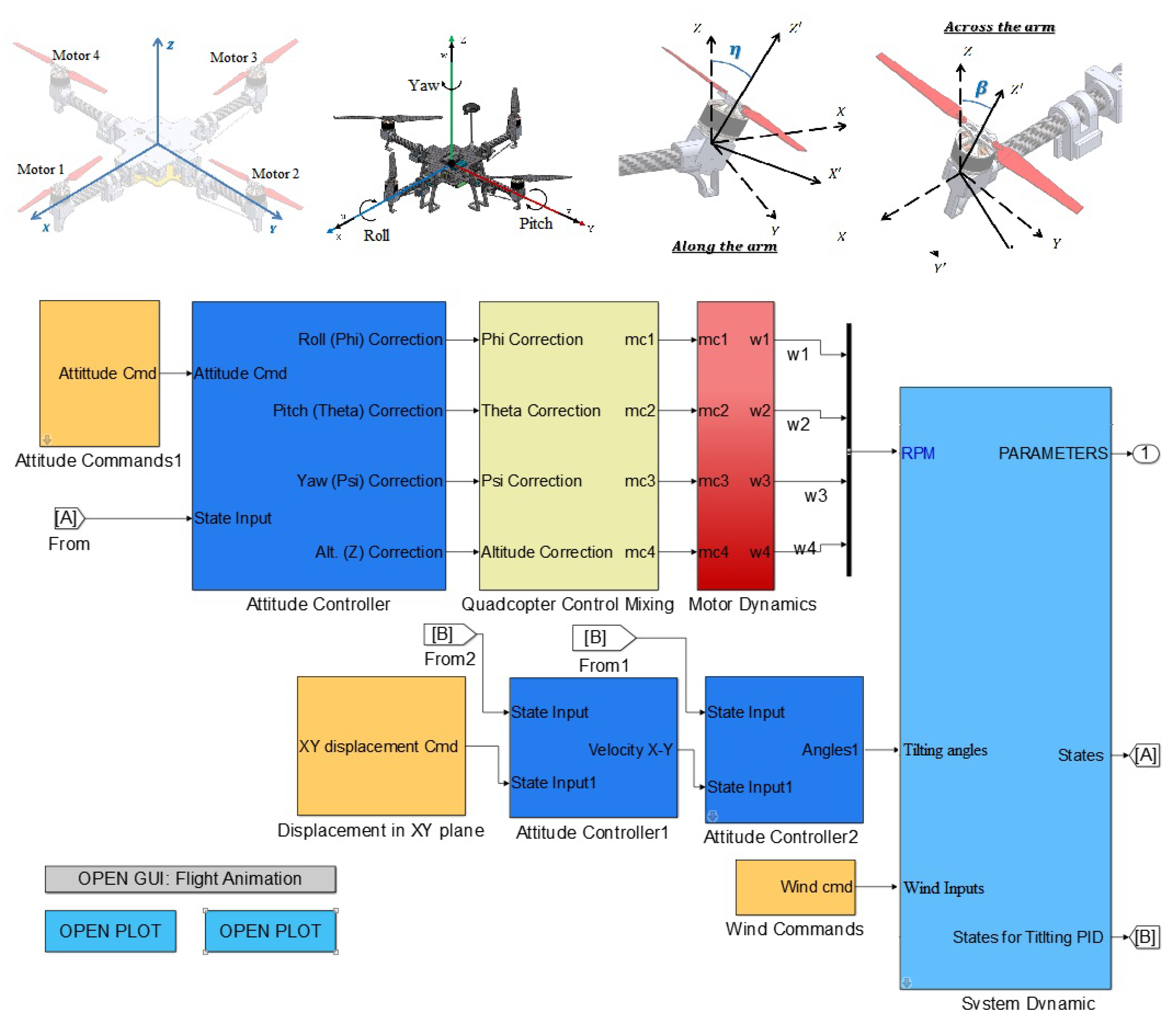
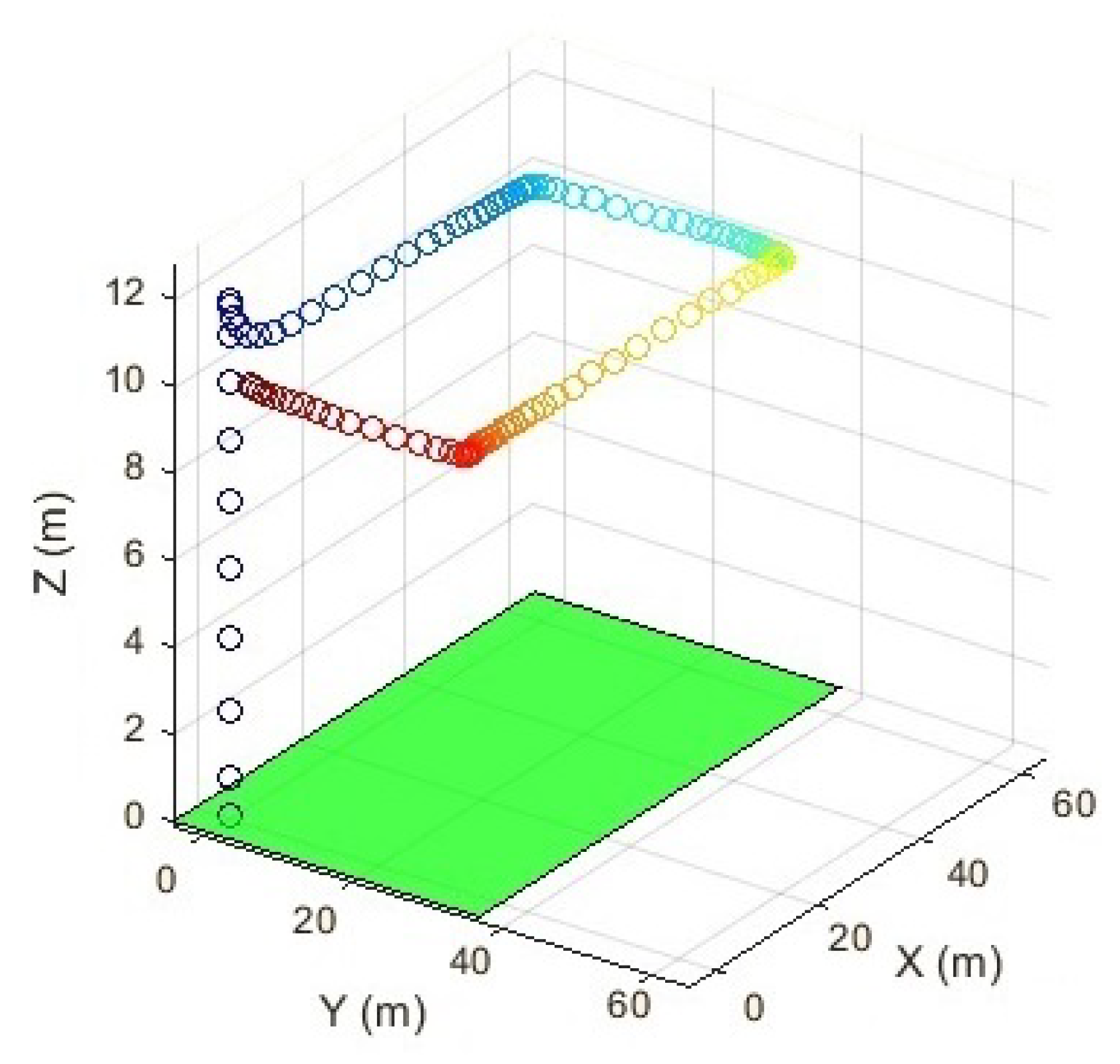
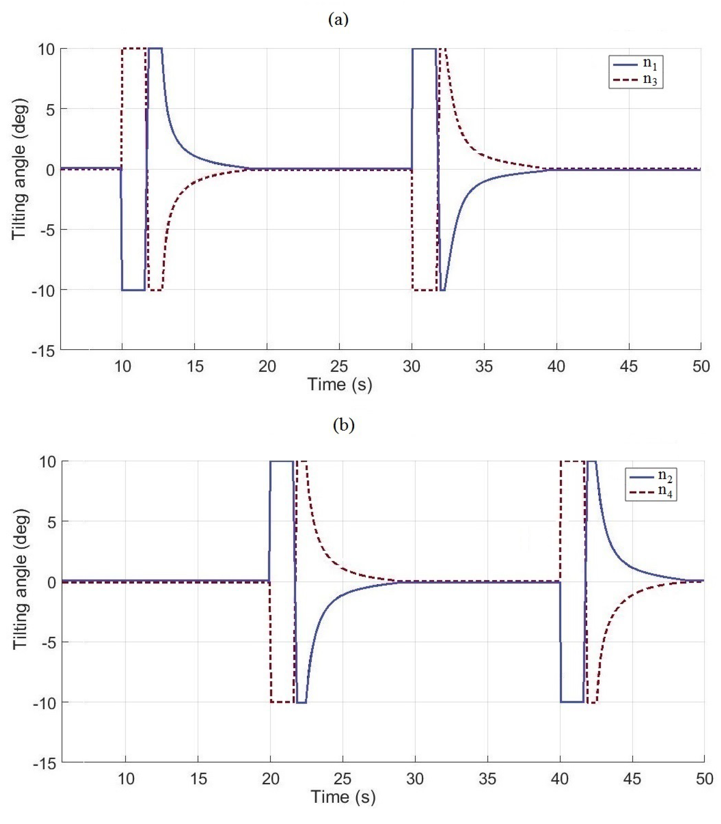
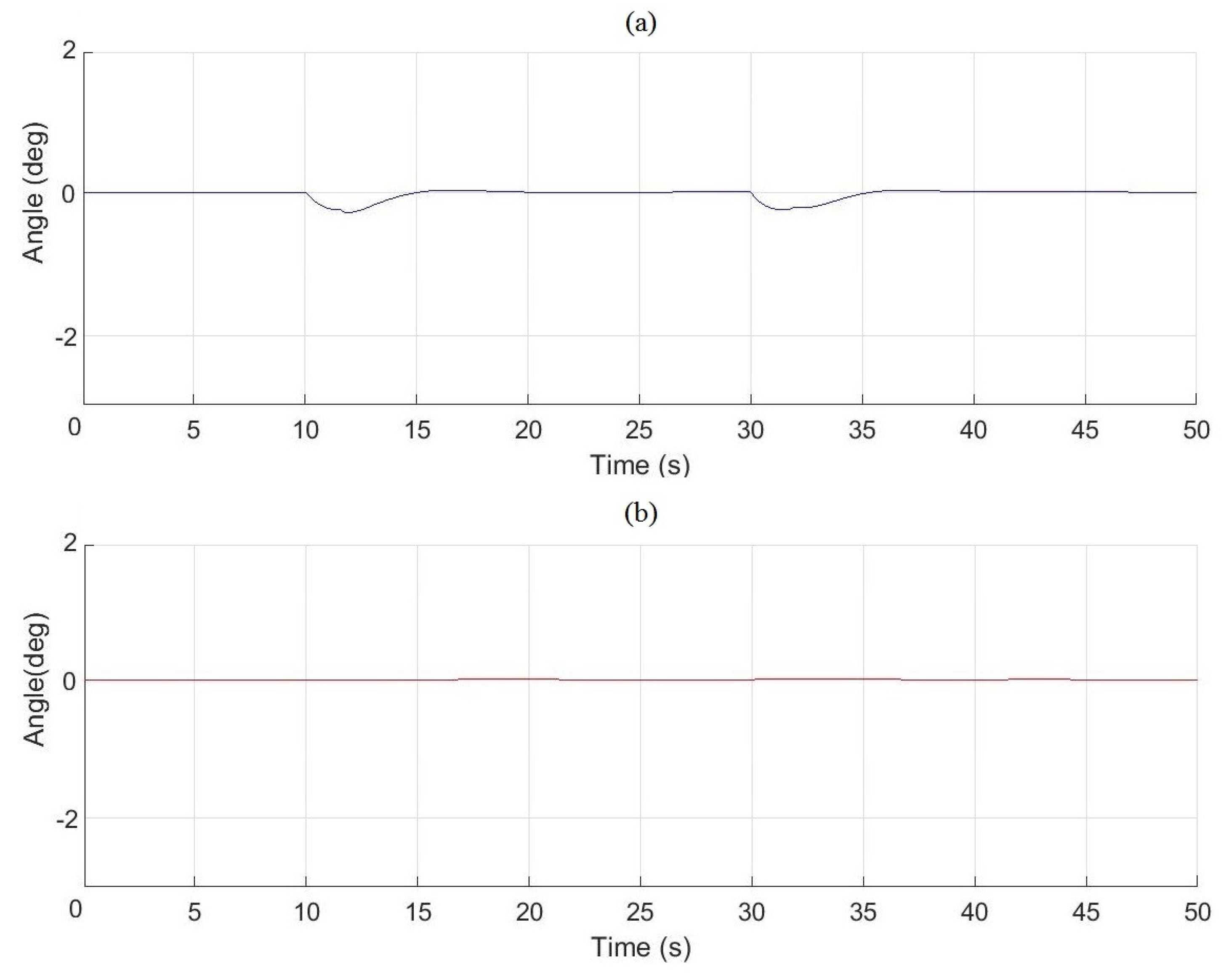
3.2. Simulation
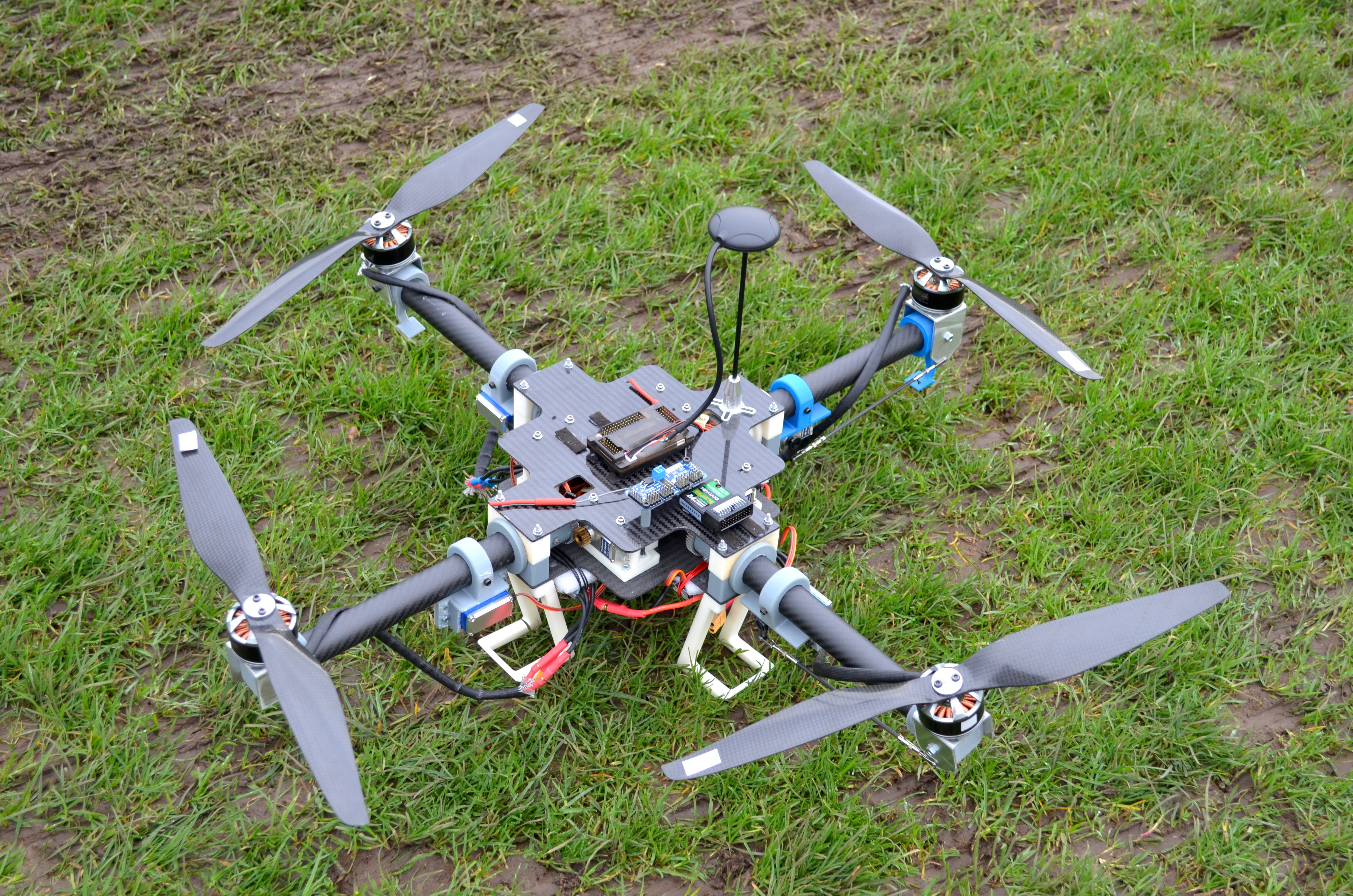
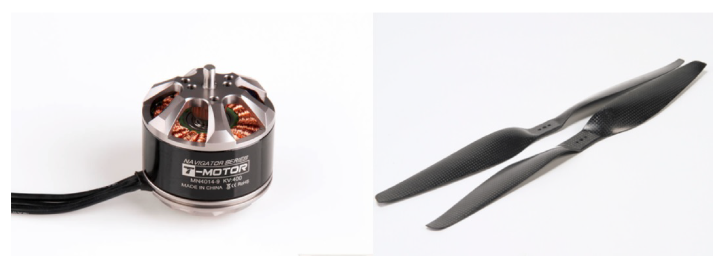
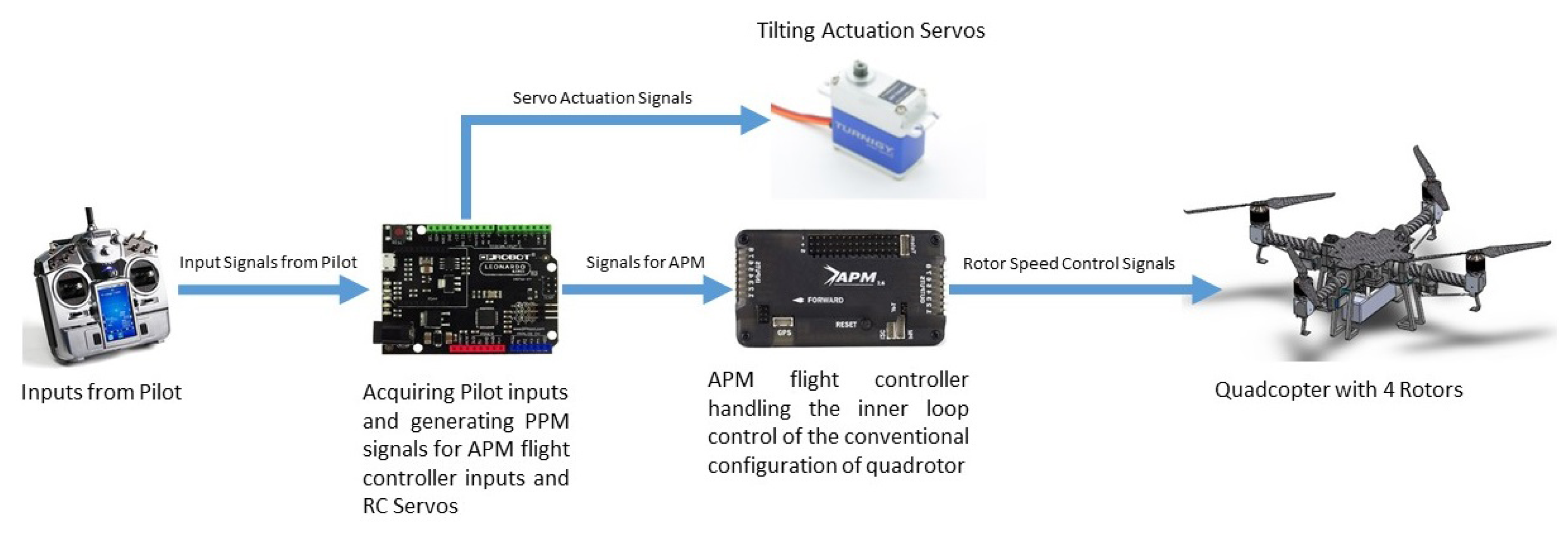
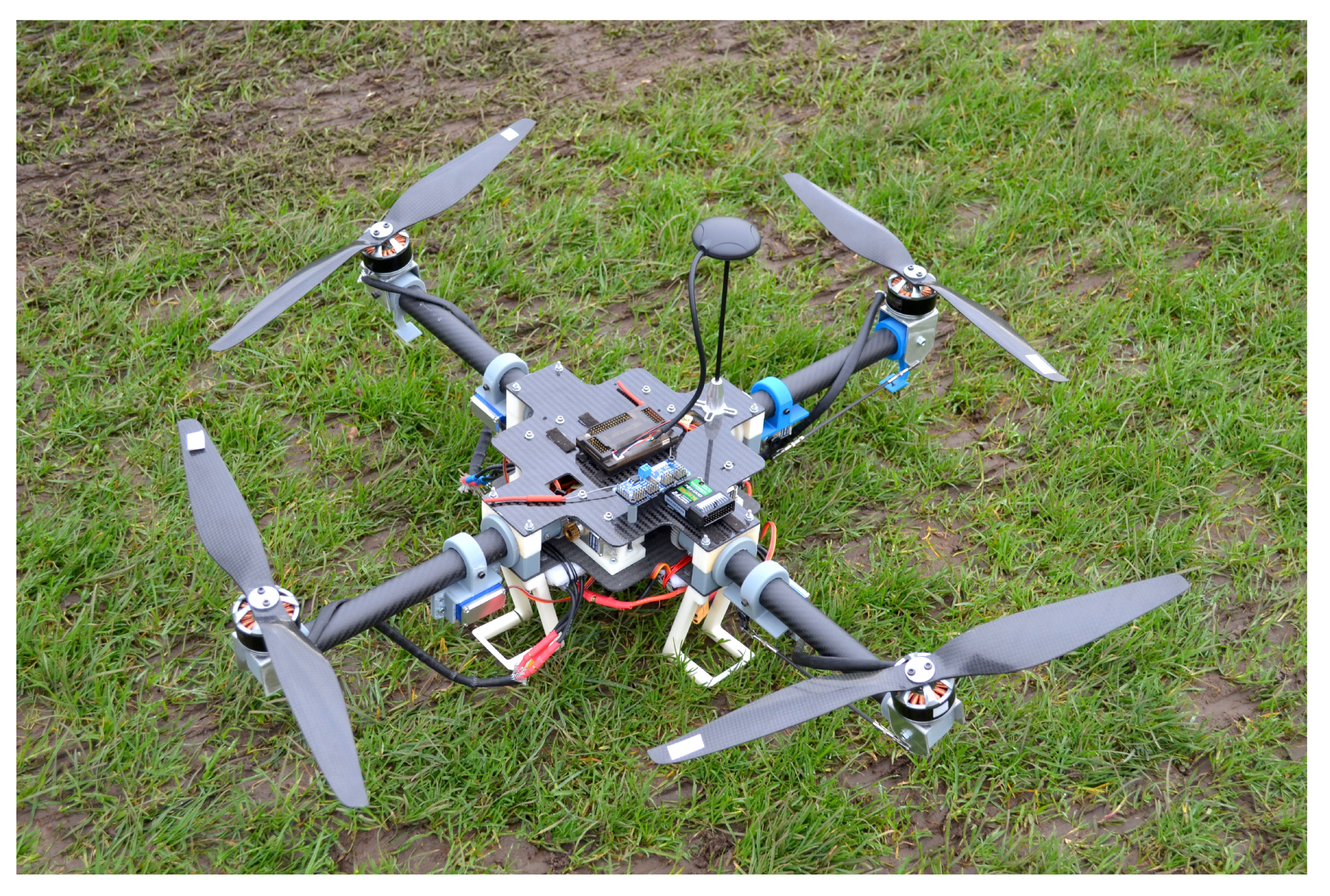
4. Experimental Setup
5. Results and Discussion
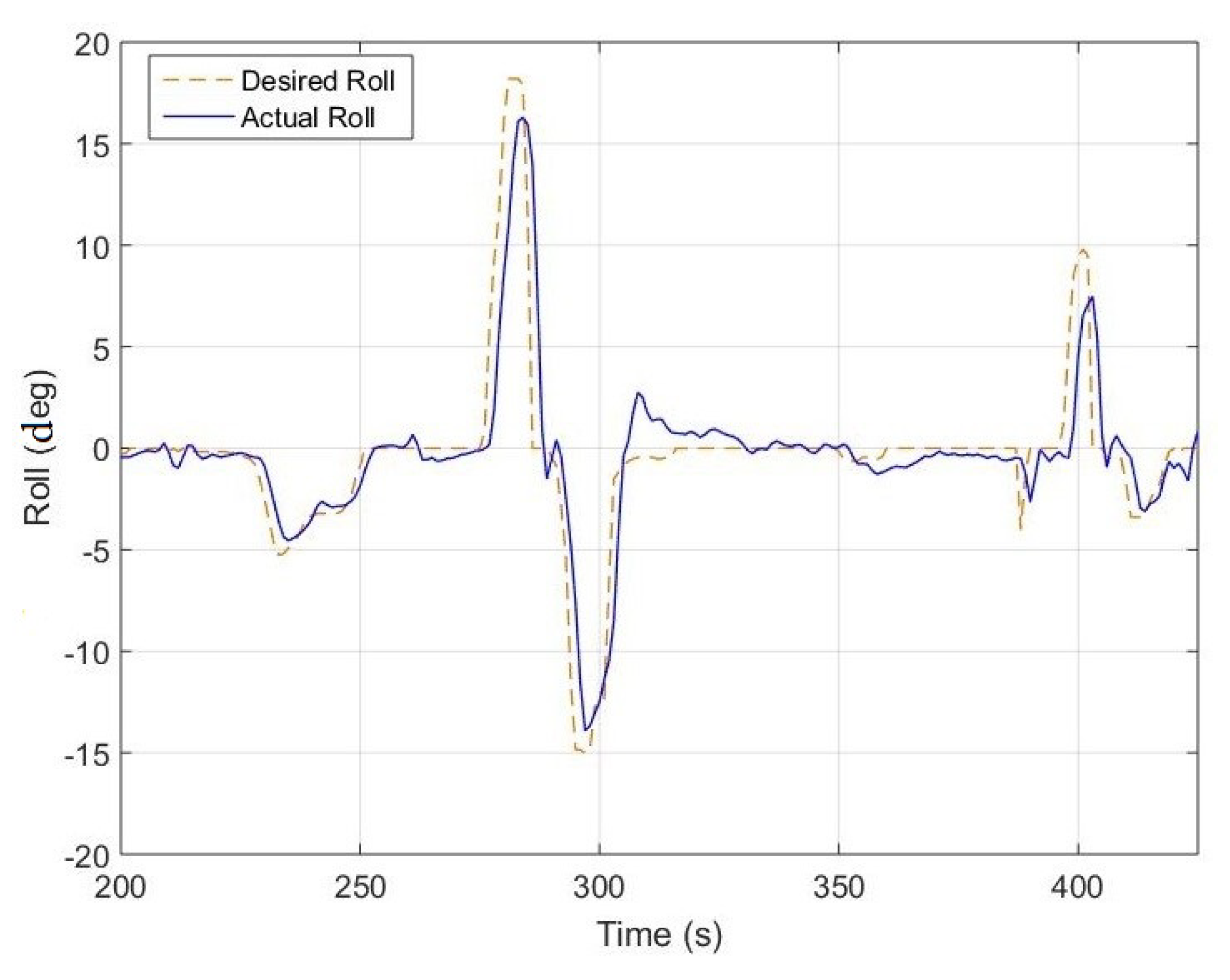
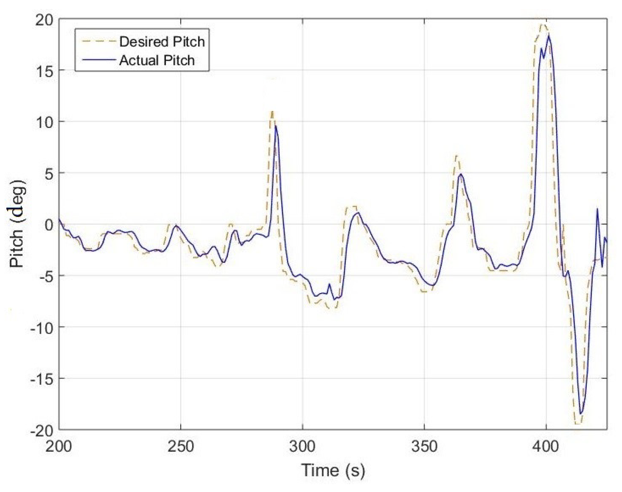
5.1. Flight Test with Conventional Actuation of Quadcopter
5.2. Flight Test with Tilting Rotors
6. Conclusions
Author Contributions
Funding
Acknowledgments
Conflicts of Interest
Abbreviations
| Pitch angle | |
| Roll angle | |
| Yaw angle | |
| Angular velocity | |
| Arm length | |
| Time derivative of inertia along X axis | |
| Time derivative of inertia along Y axis | |
| Time derivative of inertia along Z axis | |
| Body’s inertia along X axis | |
| Body’s inertia along Y axis | |
| Body’s inertia along Z axis | |
| Propeller’s inertia along X axis | |
| Propeller’s inertia along Y axis | |
| Propeller’s inertia along Z axis | |
| i | number of rotor (1, 2, 3, 4) |
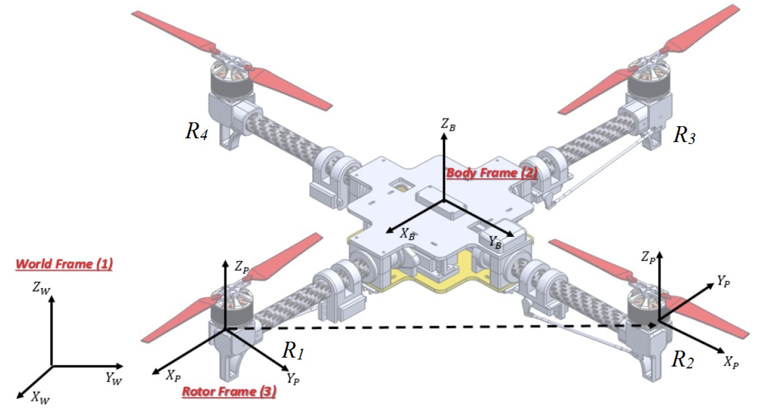
| Position in North, East and Down axis | |
| P | Angular velocity in X axis |
| Q | Angular velocity in Y axis |
| R | Angular velocity in Z axis |
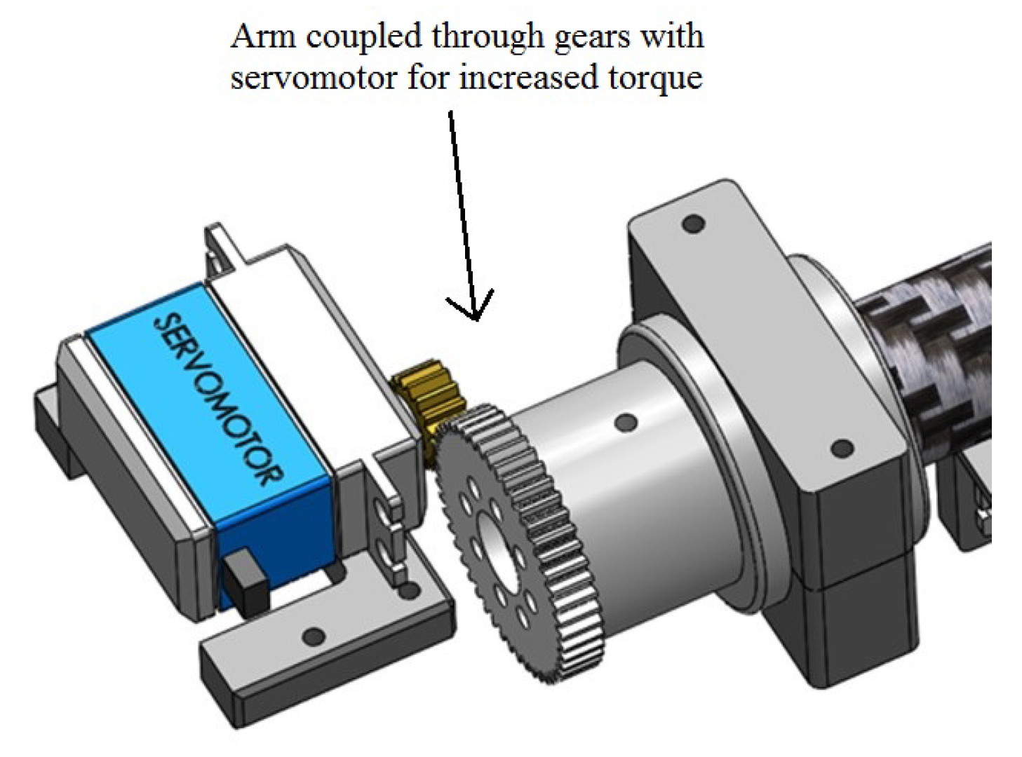
| or | Rotor tilting angle along the arm |
| or | Rotor tilting angle across the arm |
| Fixed frame (1) | |
| Body frame (2) | |
| Rotor frame (3) | |
| Rotation matrices in x, y and z axis | |
| Angular acceleration | |
| u, v, w | Linear velocity in x, y and z axis |
| Thrust generated by the rotor i |
Appendix A. Coefficients of the Forces and the Torques
Appendix B. Inertia Values
References
- Mahony, R.; Kumar, V. Aerial Robotics and the Quadrotor. IEEE Robot. Autom. Mag. 2012, 19, 19. [Google Scholar] [CrossRef]
- Doherty, P.; Rudol, P. A UAV Search and Rescue Scenario with Human Body Detection and Geolocalization. In Proceedings of the Australian Conference on Artificial Intelligence, Gold Coast, Australia, 2–6 December 2007; pp. 1–13. [Google Scholar] [CrossRef]
- Mahony, R.; Kumar, V.; Corke, P. Multirotor Aerial Vehicles: Modeling, Estimation, and Control of Quadrotor. IEEE Robot. Autom. Mag. 2012, 19, 20–32. [Google Scholar] [CrossRef]
- Hua, M.D.; Hamel, T.; Morin, P.; Samson, C. A Control Approach for Thrust-Propelled Underactuated Vehicles and its Application to VTOL Drones. IEEE Trans. Autom. Control 2009, 54, 1837–1853. [Google Scholar]
- Hua, M.D.; Hamel, T.; Morin, P.; Samson, C. Introduction to feedback control of underactuated VTOL vehicles: A review of basic control design ideas and principles. IEEE Control Syst. 2013, 33, 61–75. [Google Scholar] [CrossRef]
- Lo, C.H.; Shin, H.S.; Tsourdos, A.; Kim, S. Modeling and Simulation of Fault Tolerant Strategies for A Quad Rotor UAV. In Proceedings of the AIAA Modeling and Simulation Technologies Conference, Minneapolis, MI, USA, 13–16 August 2012. [Google Scholar] [CrossRef]
- Morozov, Y.V. Emergency Control of a Quadrocopter in Case of Failure of Two Symmetric Propellers. Autom. Remote Control 2018, 79, 463–478. [Google Scholar] [CrossRef]
- Adır, V.G.; Stoica, A.M.; Marks, A.; Whidborne, J.F. stabilization and single motor failure recovery of a 4Y octorotor. In Proceedings of the IASTED International Conference on Intelligent Systems and Control (ISC 2011), Cambridge, UK, 11–13 July 2011; pp. 82–87. [Google Scholar]
- Michieletto, G.; Ryll, M.; Franchi, A. Control of statically hoverable multi-rotor aerial vehicles and application to rotor-failure robustness for hexarotors. In Proceedings of the 2017 IEEE International Conference on Robotics and Automation (ICRA), Singapore, 29 May–3 June 2017; pp. 2747–2752. [Google Scholar] [CrossRef]
- Cutler, M.; Ure, N.K.; Michini, B.; How, J. Comparison of Fixed and Variable Pitch Actuators for Agile Quadrotors. In Proceedings of the AIAA Guidance, Navigation, and Control Conference, Portland, OR, USA, 8–11 August 2011. [Google Scholar] [CrossRef] [Green Version]
- Oner, K.T.; Cetinsoy, E.; Unel, M.; Aksit, M.F.; Kandemir, I.; Gulez, K. Dynamic model and control of a new quadrotor unmanned aerial vehicle with tilt-wing mechanism. World Acad. Sci. Eng. Technol. 2008, 45, 58–63. [Google Scholar]
- Jiang, G.; Voyles, R. Hexrotor UAV platform enabling dextrous interaction with structures-flight test. In Proceedings of the 2013 IEEE International Symposium on Safety, Security, and Rescue Robotics (SSRR), Linkoping, Sweden, 21–26 October 2013; pp. 1–6. [Google Scholar] [CrossRef]
- Gasco, P.S. Development of a Dual Axis Tilt Rotorcraft. Master’s Thesis, Cranfield University, Bedford, UK, 2012. [Google Scholar]
- Gasco, P.S.; Al-Rihani, Y.; Shin, H.S.; Savvaris, A. A novel actuation concept for a multi rotor UAV. In Proceedings of the International Conference on Unmanned Aircraft Systems (ICUAS), Atlanta, GA, USA, 28–31 May 2013; pp. 373–382. [Google Scholar] [CrossRef]
- Nemati, A.; Kumar, M. Modeling and control of a single axis tilting quadcopter. In Proceedings of the American Control Conference, Portland, OR, USA, 4–6 June 2014; pp. 3077–3082. [Google Scholar] [CrossRef]
- Scholz, G.; Trommer, G.F. Model based control of a quadrotor with tiltable rotors. Gyrosc. Navig. 2016, 7, 72–81. [Google Scholar] [CrossRef]
- Lim, K.; Shin, J.Y.; Moerder, D.; Cooper, E. A New Approach to Attitude Stability and Control for Low Airspeed Vehicles. In Proceedings of the AIAA Guidance, Navigation, and Control Conference, Providence, RI, USA, 16–19 August 2004. [Google Scholar] [CrossRef]
- Gress, G. Using Dual Propellers as Gyroscopes for Tilt-Prop Hover Control. In Proceedings of the Biennial International Powered Lift Conference and Exhibit, Williamsburg, VA, USA, 5–7 November 2002. [Google Scholar] [CrossRef]
- Gress, G. Lift fans as gyroscopes for controlling compact VTOL air vehicles: Overview and development status of Oblique Active Tilting. In Proceedings of the American Helicopter Society 63th Annual Forum, Virginia Beach, VA, USA, 1–3 May 2007. [Google Scholar]
- Sanchez, A.; Escareño, J.; Garcia, O.; Lozano, R. Autonomous Hovering of a Noncyclic Tiltrotor UAV: Modeling, Control and Implementation. IFAC Proce. Vol. 2008, 41, 803–808. [Google Scholar] [CrossRef]
- Klippstein, H.; Diaz De Cerio Sanchez, A.; Hassanin, H.; Zweiri, Y.; Seneviratne, L. Fused Deposition Modeling for Unmanned Aerial Vehicles (UAVs): A Review. Adv. Eng. Mater. 2017, 1700552. [Google Scholar] [CrossRef]
- Klippstein, H.; Hassanin, H.; Diaz De Cerio Sanchez, A.; Zweiri, Y.; Seneviratne, L. Additive Manufacturing of Porous Structures for Unmanned Aerial Vehicles Applications. Adv. Eng. Mater. 2018, 1800290. [Google Scholar] [CrossRef]
- Pragada, L.K.D.; Katukam, R. 3d printing of quadcopter: A Case Study. Int. J. Latest Trends Eng. Technol. 2015, 5, 131–140. [Google Scholar]
- Hooi, C.G. Design, Rapid Prototyping and Testing of a Ducted Fan Microscale Quadcopter. In Proceedings of the American Helicopter Society 70th Annual Forum, Montreal, QC, Canada, 20–22 May 2014. [Google Scholar]
- Alzu’bi, H.; Allateef, I.; Zweiri, Y.; Alkhateeb, B.; Al-Masarwah, I. Quad tilt rotor Vertical Take Off and Landing (VTOL) Unmanned Aerial Vehicle (UAV) with 45 degree rotors. Patent US20130105635, 2 May 2013. [Google Scholar]
- Ryll, M.; Bülthoff, H.H.; Giordano, P.R. First flight tests for a quadrotor UAV with tilting propellers. In Proceedings of the 2013 IEEE International Conference on Robotics and Automation, Karlsruhe, Germany, 6–10 May 2013; pp. 295–302. [Google Scholar] [CrossRef]
- Ryll, M.; Bülthoff, H.H.; Giordano, P.R. A Novel Overactuated Quadrotor Unmanned Aerial Vehicle: Modeling, Control, and Experimental Validation. IEEE Trans. Control Syst. Technol. 2015, 23, 540–556. [Google Scholar] [CrossRef] [Green Version]
- Zortrax. Zortrax M200. 2016. Available online: https://zortrax.com/printers/zortrax-m200/ (accessed on 28 September 2017).
- Guzman, M. Modeling and Simulation of an Over-Actuated Dual Tilting Rotors Quadcopter. Master’s Thesis, Kingston University, London, UK, 2015. [Google Scholar]
- Lim, H.; Park, J.; Lee, D.; Kim, H.J. Build Your Own Quadrotor: Open-Source Projects on Unmanned Aerial Vehicles. IEEE Robot. Autom. Mag. 2012, 19, 33–45. [Google Scholar] [CrossRef]


| Parameter | Specifications |
|---|---|
| UAV Dimensions | 1048 × 1048 mm |
| Weight | 4 kg |
| Endurance | 20 min |
| Payload Capacity | 2 kg |
© 2018 by the authors. Licensee MDPI, Basel, Switzerland. This article is an open access article distributed under the terms and conditions of the Creative Commons Attribution (CC BY) license (http://creativecommons.org/licenses/by/4.0/).
Share and Cite
Bin Junaid, A.; Diaz De Cerio Sanchez, A.; Betancor Bosch, J.; Vitzilaios, N.; Zweiri, Y. Design and Implementation of a Dual-Axis Tilting Quadcopter. Robotics 2018, 7, 65. https://doi.org/10.3390/robotics7040065
Bin Junaid A, Diaz De Cerio Sanchez A, Betancor Bosch J, Vitzilaios N, Zweiri Y. Design and Implementation of a Dual-Axis Tilting Quadcopter. Robotics. 2018; 7(4):65. https://doi.org/10.3390/robotics7040065
Chicago/Turabian StyleBin Junaid, Ali, Alejandro Diaz De Cerio Sanchez, Javier Betancor Bosch, Nikolaos Vitzilaios, and Yahya Zweiri. 2018. "Design and Implementation of a Dual-Axis Tilting Quadcopter" Robotics 7, no. 4: 65. https://doi.org/10.3390/robotics7040065