1. Introduction
In the contemporary industrial landscape, robots are not only being progressively employed in traditional confined workcells but they are also assuming crucial roles in collaborative applications, operating in cooperation with their human counterparts. In this context, robotic grippers are the most common end-effectors through which robots perform grasping tasks and interact with the surrounding workspace.
Robotic grippers can be categorized based on several factors, including the number of fingers (typically two or three), type of actuation (such as pneumatic or electric), and construction material used (either rigid or soft) [
1]. In the past decade, although research has advanced, leading to smarter technology and design [
2] for these devices, applications foreseeing fully open or closed behavior have continued to dominate real-world applications due to their simplicity and lower costs. In fact, the number of works dealing with control strategies, particularly closed-loop ones, for industrial robotic grippers is still rather limited [
3].
Two-fingered pneumatic rigid grippers are the most commonly used in modern industry. Generally, they have advantages such as cost-effectiveness and a wide range of gripping forces. Nonetheless, they can be difficult to control and often function as simple fully open/closed devices [
4]. Despite the well-known challenges in the control of pneumatic grippers, some interesting closed-loop architectures were presented in recent years for force control [
5] and position control [
6]. Traditional sensors, such as load cells and encoders, were employed in these studies. Soft pneumatic grippers were also tested with closed-loop control of the gripping force, although their performance is affected by slow response, high nonlinearity [
7], and complex modeling [
8]. Generally, the closed-loop force control of pneumatic grippers requires a number of sensors (at least for force and pressure). The addition of such sensors causes the costs to increase, thus undermining one of the greatest advantages of these grippers over other types.
On the other hand, electric grippers are easier to control, at least in terms of finger position and velocity. In [
9], each finger was driven by an independent DC motor. One finger was only position-controlled through a proportional–integral–derivative (PID) action, while the remaining finger was force-controlled by a PI cascaded with a further position PID controller. A clear limitation of this work lies in the very limited force interval explored, i.e., a maximum of 10 N. Electric grippers can be affected by considerable backlash and force-dependent friction. In [
10], a backlash compensation method coupled with feed-forward friction compensation was proposed. Despite this valuable control approach, the above limitation (low force range) also applies to this work. A three-fingered gripper, with each finger driven by a DC motor equipped with an encoder, was presented in [
11]. Position control and force control were, respectively, achieved using a PID action and a proportional action for each finger. In particular, the force control action was used to add compliance to the position control. Force feedback was obtained from piezoresistive sensors, one per finger. However, the evaluated forces were rather small, i.e., limited to 8 N. Moreover, a closed-loop control was applied to a simulated two-fingered parallel electric gripper in [
12]. This control strategy included a position-force switching method, resorting to model predictive control, a PD controller for the position loop, and a PI for the force loop. No experiments were conducted on real grippers and, again, low forces were tested.
At the research level, there were some attempts to instrument grippers with tactile sensors, and recent examples can be found in [
13,
14]. These sensors can enable distributed measurements on the contact area between the object and the sensor, delicate object handling, and the detection of slippage, among other capabilities [
15]. However, they still suffer from low reliability and robustness compared to more traditional force, torque, or position sensors, which explains the fact that they are almost completely disregarded outside research labs.
Simulations can be employed to support gripper design and predict their behavior before fabrication. For example, in [
16], a design optimization method for robotic grippers based on dynamic grasping simulations was proposed. The geometrical parameters of the gripper, along with common quality indexes, were employed for the optimization design.
In general, simulations can suggest interesting research paths. Indeed, a well-constructed model might be able to predict a system’s behavior under a defined ensemble of theoretical conditions. From the verification of the predicted behavior, even more deductions are possible, and the model can be enriched with details deriving from the experiments.
In this context, open-loop control strategies for robotic grippers could be favored through the joint use of simulations and hardware (see e.g., [
17]). Such an approach may prove particularly helpful in the absence of force or torque sensors when the gripper behavior cannot be managed in a reliable way beyond the open/closed configuration. The literature does not provide approaches for open-loop force control, thus inducing users to rely on expensive grippers that can cost up to USD 10,000. Furthermore, as can be evinced from a very recent publication [
18], approaches involving sensorized fingers on industrial robotic grippers are particularly rare. With this in mind, it is worth investigating the open-loop force behavior of grippers as a simpler alternative to the costly and often complex integration of sensors.
Therefore, this article aims to enhance the understanding of the open-loop grasping force behavior of robotic grippers. The idea is to deliver an approach for grasping items that exploits high finger velocities without pre-positioning the gripper fingers. That is, with no knowledge of the size of the item to be grasped, which is commonly a priori known when working with robotic grippers [
19]. The proposed approach features two macro-steps, i.e., one defining the gripper model and another executing the experiments, allowing a direct comparison between the results of both macro-steps. Eventually, more iterations of comparisons might be performed. The main contributions of this work can be summarized as follows:
A model-based approach, which, through a continuous comparison of simulated and experimental data, could enhance the understanding of peculiar gripper static and dynamic behaviors.
Optimization of the gripper’s grasping behavior acting on the finger contact interface, thereby increasing force repeatability and reducing unwanted peaks, i.e., keeping the gripper mechanics safe.
The proposed strategy does not require knowledge of the object’s size, unlike common robotic grasping with industrial grippers. In particular, the focus is on the gripper exerting force laterally onto the object [
19], as demonstrated in the present study.
The proposed strategy allows the gripper to contact rigid objects at high speed (33.5 mm/s in the present case) without decelerating the fingers in proximity to the object to be grasped.
The proposed strategy does not require force and torque sensors.
The approach summarized above was covered by a patent application recently submitted [
20].
A robotic gripper with a set of requirements was built, and its Matlab-Simulink-Simscape model was developed accordingly. The model helped us understand some peculiarities of the gripper’s performance in both static and dynamic conditions. Then, the hypotheses obtained through the model were experimentally validated. A large number of grasping trials, i.e., 6000, were executed, together with the static force characterization. The latter was useful in preliminarily assessing the model and tuning its parameters. Overall, the proposed model-based approach proved how to ameliorate the grasping force behavior without resorting to closed-loop force control strategies.
To the best of the authors’ knowledge, this is the first attempt to conduct research on the grasping force behavior of robotic grippers by combining a detailed mathematical model with rigorous experiments. The present work does not define an open-loop force control strategy; nonetheless, it proposes an approach to achieve the optimization of the grasping force behavior, paving the way toward sensor-less, open-loop force control.
The remainder of the article is structured as follows.
Section 2 illustrates the gripper,
Section 3 describes the gripper model,
Section 4 shows the setups and the experiments,
Section 5 discusses the proposed approach and, finally,
Section 6 presents the conclusions.
2. Gripper Design
A gripper with a maximum continuous gripping force of 150 N and a stroke of 50 mm was designed. Such requirements are in line with commercial grippers for industrial applications, although devices with higher forces and larger strokes are available in the market (referred to in
Section 6). It is essential to emphasize that the constructed gripper does not represent a scientific contribution, as it is composed of off-the-shelf components. Instead, it serves as a technical tool for pursuing the scientific scope of the present work.
The gripper was actuated by a 24 V brushless motor, namely a permanent magnet synchronous motor (PMSM). Its nominal current was 3.3 A, and its nominal torque was 0.13 Nm.
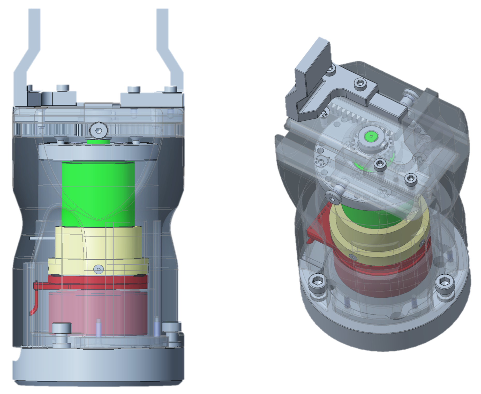
Figure 1 shows two views of the gripper’s CAD model, designed with Creo Parametric. The motor’s angular position was sensed by an incremental encoder (resolution: 2048 cpt) mounted on the motor’s PCB, which boasted three hall sensors.
The PMSM was coupled with a braking element that featured a maximum torque equal to 0.14 Nm, which is not further detailed as it was not used in this study. The brake was, in turn, connected to a two-stage planetary gearhead with an overall reduction ratio of :1, which was selected so that its maximum continuous input speed of rpm was higher than the declared motor no-load speed of rpm. The chosen reduction ratio was chosen to cover the specified force interval, given the motor’s nominal torque.
The planetary gearhead drove a rack-and-pinion mechanism that synchronized the movement of the two gripper jaws. Each jaw could slide in a separate T-shaped guide.
Finally, the so-conceived mechanism was packaged in light aluminum covers that could be easily assembled and, when required, dismounted. More details about the fingers are provided in the next section.
3. System Modeling
In this section, the system model developed in the Simulink-Simscape environment is detailed.
The definition of a detailed system model, from the actuation components to the finger mechanics, is the first macro-step in the proposed approach, once the gripper is available (either constructed or built by the user, as in the present study).
Despite the absence of force control, closed-loop velocity and current controls were necessary to drive the electric gripper.
3.1. Control
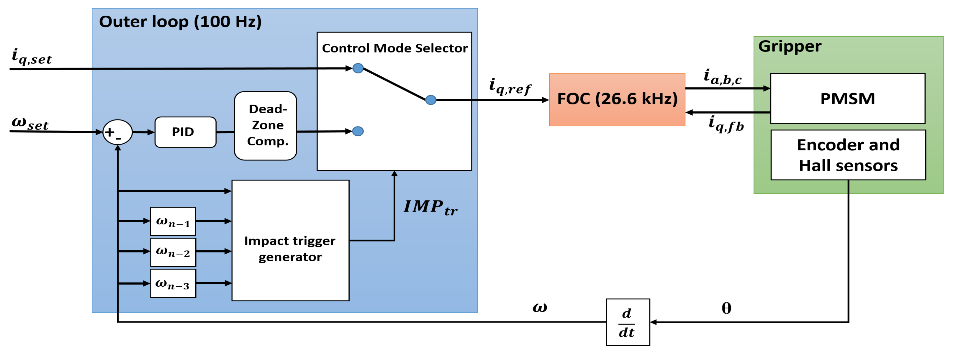
The control architecture, shown in
Figure 2, consists of two main parts:
Figure 2.
Control architecture overview.
Figure 2.
Control architecture overview.
The OL implements the closed-loop velocity control, utilizing a PID mechanism. The motor’s angular position
was provided by the incremental encoder, whereas the motor’s velocity
was analytically estimated by differentiating the position measurement. A motor dead-zone compensation logic was added to improve the velocity PID action, providing an offset current
, which helped unblock the jaws within the motor’s dead-zone (i.e., ±0.2 A). This is particularly useful for low-amplitude setpoints, where the sole PID output current
may be too small to move the system out of the dead zone, causing response delays. The compensation logic is shown in (
1), where
is the velocity tracking error, and
is the minimum tracking error threshold, above which compensation occurs:
is the quadrature current, i.e., the input to the FOC algorithm, which is a well-known method for controlling synchronous motors [
21]. The control mode selector is able to perform a real-time automatic velocity-current switch when an impact is detected. The impact trigger algorithm receives four velocity samples, i.e., the current one
and the three previous ones
,
, and
. The
flag will be raised according to (
2):
The parameter was determined experimentally. When in velocity mode, the OL output coincides with . Instead, when in current mode, coincides with the setpoint . The three motor phase currents are controlled in the d-q rotating reference frame through two PIs, within the FOC. The direct current is minimized. The direct and inverse Park and Clarke transform allow for the mathematical transformation of the motor currents from the three-phase static reference frame to the rotating d-q one. To start the motor shaft rotation, information from the hall sensors was utilized to align the magnetic fields of the PMSM stator and rotor. Thereafter, only the encoder output was employed to manage the motor angular position, and consequently, the linear motion of the jaw.
3.2. Electric Motor
The electric motor, namely the permanent magnet synchronous motor (PMSM), was modeled using a PMSM Simscape block. The principal equations governing the motor functioning were implemented within the block:
where
,
and
,
are the voltages and currents defined in the d-q reference frame;
is the phase resistance;
P is the number of pole pairs;
is the motor angular velocity; and
is the permanent magnet flux linkage.
can be linked to the motor torque constant
through
P, such that
. The d-q axis inductances
and
are:
where
is the phase self-inductance,
is the inductance fluctuation, and
is the mutual inductance. The motor torque
T is calculated as follows:
The rotor damping
can be inferred from (
6):
where
and
are the no-load current and motor velocity, respectively. The model can solve the torque balance (
7) by knowing the rotor’s inertia
:
where
is the load torque and
is the motor angular acceleration.
Although some parameters were set according to the PMSM datasheet, a number of parameters were directly required by the manufacturer in order to achieve a detailed model that relied on the above equations. These parameters were , , , and .
3.3. Gearbox
The planetary gearhead was modeled using a
Simple Gear Simscape block, with the above-specified reduction ratio
and a constant efficiency
. A rotational inertia
was connected to the block, as well as a rotational damper modeling the bearing damping
:
where
and
are the maximum gearbox torque and rotational velocity, respectively. Equation (
8) can be reformulated taking into account the motor quantities:
where
and
are the motor’s maximum torque and velocity. Finally, a rotational hard-stop block models the shaft rotational play, i.e., 0.8°.
3.4. Jaw-Finger Mechanics
The jaw-finger mechanics were modeled using an ad hoc Simscape block, namely
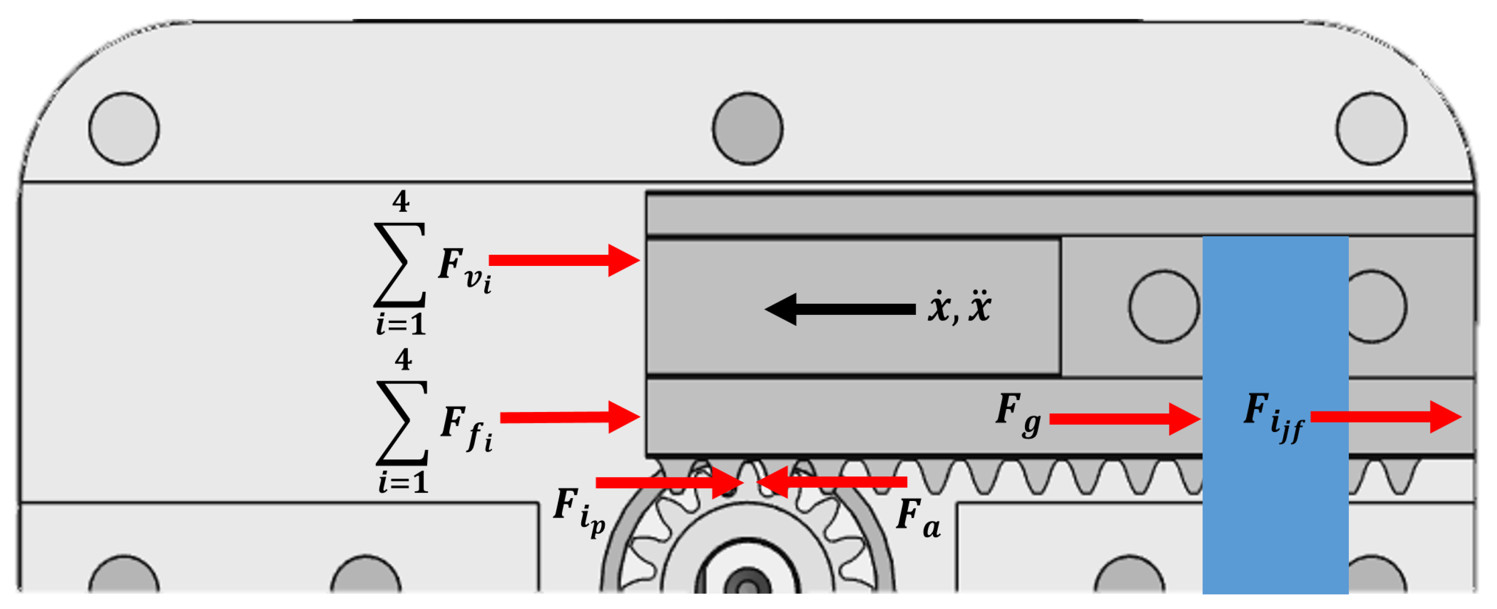
component. It solves equations in a non-causal manner, according to the Simscape philosophy. The block takes into account both the force and momentum equilibria. The horizontal force equilibrium (
Figure 3) is:
where
is the gripping force;
is the actuation force provided by the gear shaft; and
,
,
, and
are, respectively, the shaft inertial force, jaw-finger inertial force, static friction forces, and viscous force acting on each of the four contact surfaces of the jaw. In more detail:
where
is the dynamic viscosity of the grease used,
is the i-th sliding surface area,
d is the distance between the sliding planes (i.e., the grease layer thickness), and
and
are the linear velocity and acceleration of the jaw-finger subsystem.
,
, and
are, respectively, the inertia, angular velocity, and radius of the pinion;
is the overall mass of the jaw finger, and
is the friction coefficient of the i-th jaw surface. All these quantities were either a priori known (e.g., via CAD) or measured using virtual sensors available in the Simscape library. Finally, the constraint reactions
were obtained from the vertical force equilibrium and the momentum equilibrium. Similar reasoning applies to the definition of such equilibria; therefore, they are not reported for the sake of brevity.
3.5. Mechanical Contacts
The finger contacts were modeled using springs and dampers depending on the experimental conditions to be simulated. In the Simscape environment, the series of finger and plastic interfaces, i.e., ABS cylinders (see later), were modeled using a translational hard-stop block. The stiffness value of the cylinder
can be estimated analytically. Let us assume that this element undergoes pure compression when hit by the finger:
where
is the ABS Young’s modulus,
A is the cross-sectional area perpendicular to the applied force, and
is the initial length of the cylinder. The value obtained was
N/m.
The finger stiffness
can be approximated by considering the finger as a cantilever beam, with a load applied at a distance
L from the constraint, i.e., from the center of the cylinder’s front surface to the screws fixing the finger on the jaw:
where
is the Young’s modulus of the finger aluminum, namely 6082-T6, and
is the second moment of the area of the finger’s rectangular top cross-section, resulting in
N/m. A finer estimation was determined using the Finite Element Method (FEM) analysis to better account for the nonlinear shape of the finger. For this purpose, the application point of the normal load was set at the center of the distal, square area of the finger, i.e., the actual gripping area. The results are depicted in
Figure 4, where a load of 150 N, i.e., the maximum possible with the conceived gripper, was considered.
From this analysis, the displacement of the finger at the load application point was determined to be 0.1024 mm. Hence, the value
N/m was derived, which is very close to the analytical result of Equation (
13). To confirm the soundness of the mechanical structure, the results of the FEM showing the Von Mises stresses are shown in
Figure 5. Apart from singularity points, which correspond to colors ranging from red to light green, i.e., from ca. 434 MPa to around 173 MPa, the majority of stresses were lower than 130 MPa. Considering the material yield strength to be twice this value, even forces slightly higher than 150 N (as one can see from
Section 4.4) are considered acceptable. Please note that the singularity points are not displayed as they do not represent the physics underlying the finger deformation.
Regarding the finger coatings, three different polymer fabrics were used, namely P1, P2, and P3. As demonstrated later, the aim is to understand which of them better improves the gripper behavior when grasping the object, offering the best match between experiments and simulations. The fabrics were considered to have two different stiffness and damping regions throughout their deformation. The first region of the i-th fabric had low stiffness , whereas the second one had a higher stiffness preventing the finger coating from over-deforming beyond its physical limit. Therefore, for all the fabrics, a nonlinear spring and a variable damper were adopted. Through a Matlab function, damping and stiffness values were fed to the corresponding blocks, according to the deformation zones.
The stiffness value
of the first region can be estimated using Equation (
12), where the stiffness of the second region
was set high enough to guarantee very low compressibility. The determined stiffness values were
N/m,
N/m, and
N/m. When used, the fabrics covered the entire gripping surface of the fingers, and their thickness was 2.5 mm. By commanding the gripper to close its fingers with no objects in between and using the maximum possible current, i.e., 2.5 A, the physical limit between the two stiffness regions of each fabric could be found by exploiting the encoder measurement. In the second region,
was set.
Finally, the damping coefficients were defined. A small Ns/m was set in the first region to minimize viscous reaction forces. This value was raised to Ns/m in the second region to achieve simulation stability, avoiding undesired oscillations during impact and the steady state. Both and applied to all the fabrics. The hard-stop damping of the ABS finger series was set so that .
4. Experiments
In this section, the experiments are discussed. This is the second macro-step in the proposed approach and aims to directly compare the experimental output with the simulations. Once the simulations and experiments match satisfactorily, the approach’s implementation can be deemed successful.
The same control architecture as shown in Figure
2 was adopted to pilot the real gripper.
4.1. Experimental Setup
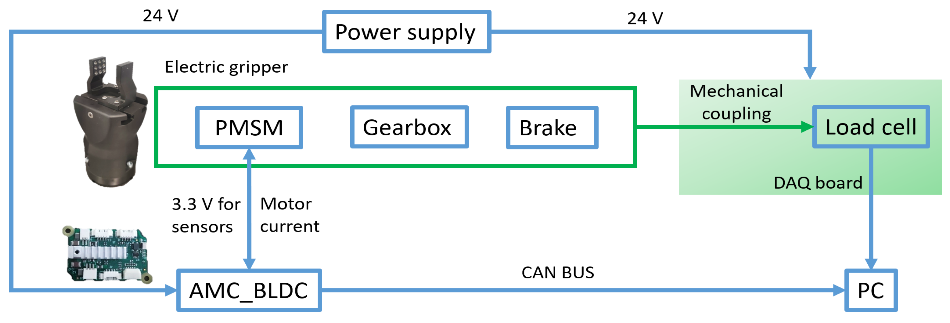
The overall schematic of the experimental setup constructed is shown in
Figure 6. The AMC_BLDC control board, which was previously developed by the i-Cub tech department (Italian Institute of Technology) to drive brushless motors, was employed. This board powered the motor with its nominal 24 V voltage, as well as the encoder and hall sensors with 3.3 V. The maximum current the board could deliver to the motor was 2.5 A, which was sufficient for the purposes of the present study. The board communicated with a computer through the
VN1610 CAN interface using Vector, receiving actuation commands and sending back the motor currents, position, and velocity data. The high-frequency FOC algorithm ran on the control board, whereas the OL ran on a dedicated computer running Matlab-Simulink.
An
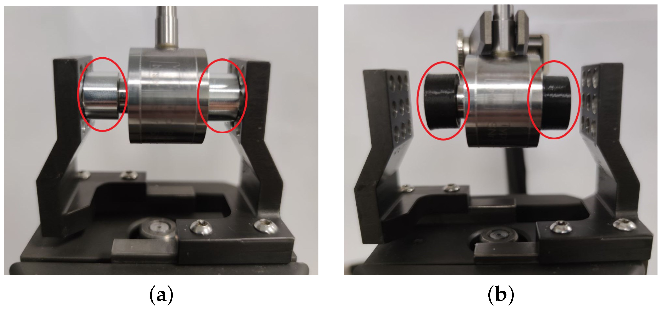
8432-5500 load cell by Burster Italia was placed between the gripper fingers to read the gripping force (21.9 mm in length). During the static experiments, the load cell was connected to the fingers via two 8 mm aluminum cylinders, designed with Creo Parametric, to reproduce an intermediate grasping position. The cylinders were secured on both sides of the load cell, as depicted in
Figure 7a, and were interfaced with the fingers through a pin fitting into a blind hole cut on the finger’s front surface. This ensured precise positioning during static load cycles.
During the dynamic experiments, the load cell was equipped with protective 3D-printed ABS cylinders, as shown in
Figure 7b. The cylinders, designed with the same software mentioned above, were again 8 mm in length to replicate the static finger’s position. Unlike the aluminum cylinders, these had flat surfaces without pins. A support stably held the load cell in the middle of the grasping area.
An
USB-6210 DAQ by National Instruments was used to sample the load cell signal at 100 Hz. The power supply also sent 24 V to the load cell amplifier (not shown in
Figure 6).
4.2. Static Behavior
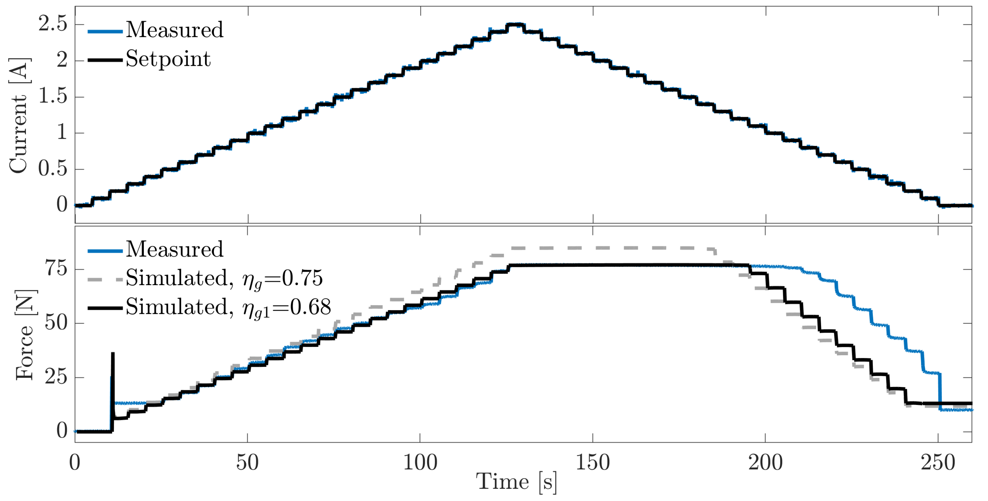
A static characterization of the gripper force was first carried out to evaluate the accuracy of the model in such a scenario. The experiment was repeated three times, yielding almost identical results. The gripper was controlled in current mode with 0.1 A increments, each lasting 5 s, up to the maximum current possible, i.e., 2.5 A.
Figure 8 shows a comparison between one of the three experimental curves and two of the simulated ones. The latter curves were produced by setting a gearbox efficiency of
, i.e., the value declared in the gearbox datasheet, and a lower value of
. It is worth noting that
was selected in order to achieve the lowest possible discrepancy between the simulation and experimental data. This value more accurately represented the actual gripper static behavior, suggesting that the datasheet’s efficiency might be slightly higher than reality. For consistency, this value was also utilized in the dynamic analysis, which is demonstrated later.
Generally, both of the simulated results showed accurate tracking of the actual gripping force. When the current setpoint was increased, the curve almost completely overlapped with the experimental one, whereas the curve slightly diverged toward higher forces, with a final value of 84.7 N at 2.5 A. This value was about 8 N higher than the 76.8 N maximum level of the experimental curve. Also, the initial force peak caused by the gearbox rotational play was reproduced in the simulation: the experiment showed a peak of 25.6 N, whereas the simulation yielded close values (i.e., 33 N for and 36 N for ).
Both the simulated results reproduced the motor dead zone, although they did not feature the constant 13.2 N force level observed from 0.2 to 0.4 A. Even though this friction effect was not captured, both the simulated curves captured the friction with decreasing input currents, albeit with a small delay. The experiments showed a constant force from 2.5 A to about 0.9 A, whereas in the simulated curves, the force started dropping at 1.1 A () and 1.3 A (). Finally, the experimental curve exhibited a residual force of 10 N when the current setpoint returned to zero. Both the simulated curves replicated this effect with very similar values, i.e., 13.1 N () and 11.9 N ().
Therefore, the developed model was generally able to replicate the hysteretic behavior of the actual gripper.
4.3. Dynamic Behavior—Preliminary Analysis
Dynamic tests were conducted to assess the gripping steady-state forces when the fingers impacted a rigid item with controlled velocities. In our case, this item was represented by the rigid ABS cylinder described earlier. These dynamic experiments aimed to demonstrate that through the proposed approach, it is possible to grasp rigid items with high velocities, i.e., up to 33.5 mm/s.
Crucial insights about impact dynamics can be derived from simulations utilizing the velocity-current control switch mode (see
Section 3.1), making use of the
variable. Initially, simulations were performed to gain an understanding of the gripper’s grasping force behavior. Subsequently, experiments were performed to confirm the model hypotheses.
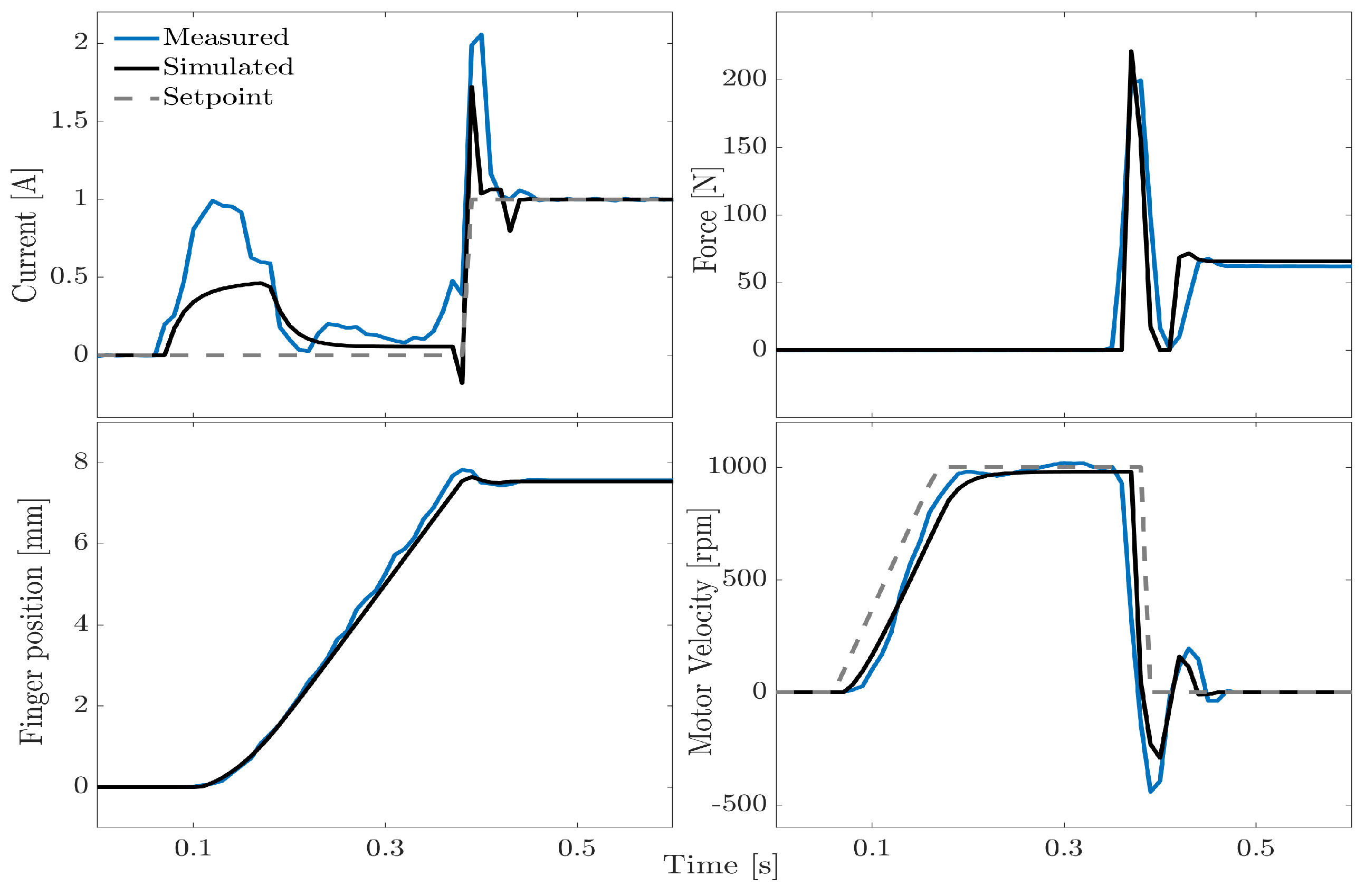
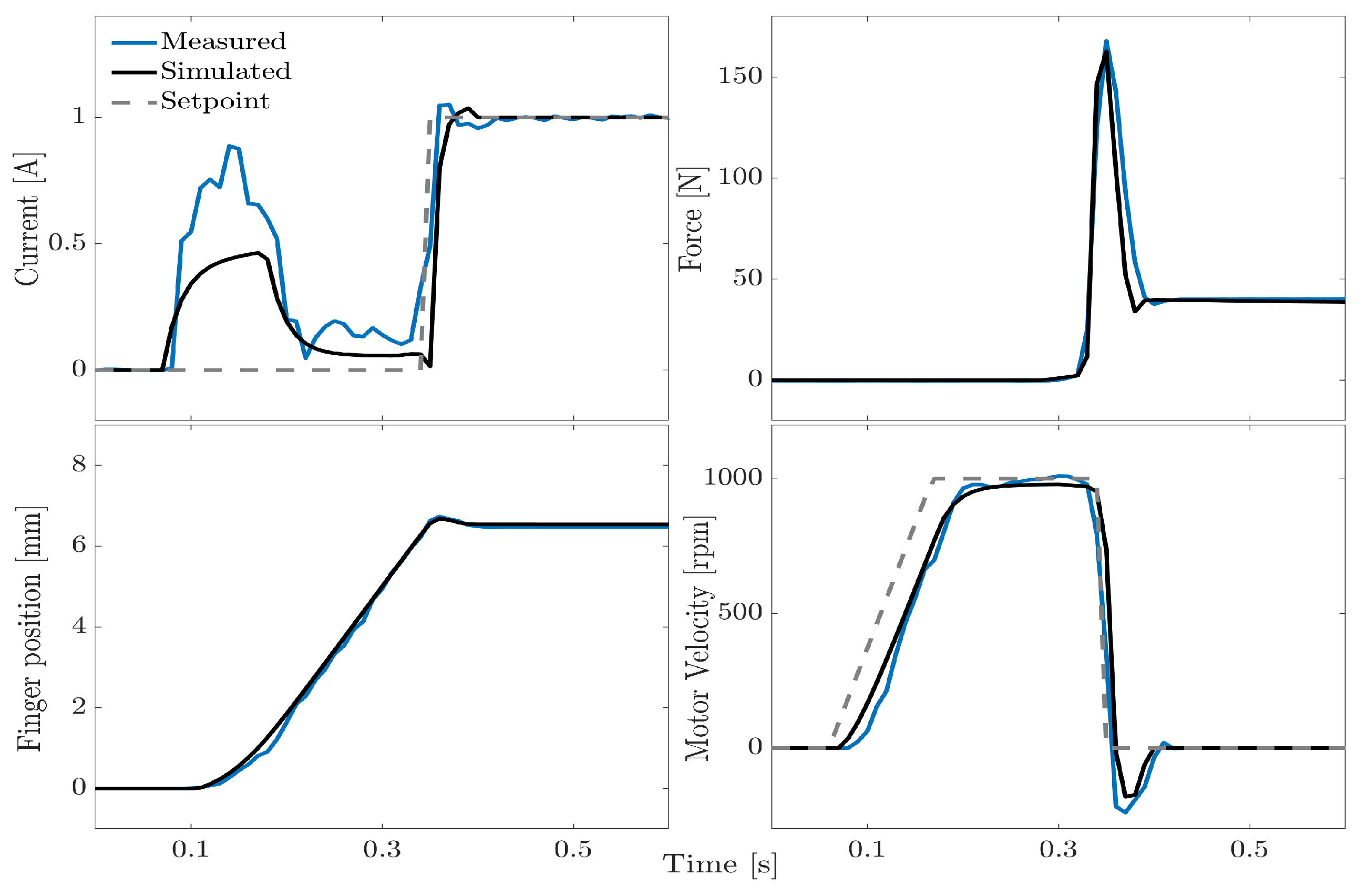
Figure 9 shows a representative comparison with the experimental data. The finger velocity was set to reach 1000 rpm through a ramp setpoint and once the ABS cylinder’s flat surface was impacted, a tightening current of 1 A was automatically applied, thanks to the aforementioned switch. The model effectively captured the overall behavior of all the gripper parameters, although the motor current seemed to be higher during the velocity ramp. The force subplot highlights the fingers bouncing on the load cell, due to the high stiffness of the contacts. This caused the gripping force, after an initial, uncontrolled peak, to drastically decrease and in some cases, become null. Even though this effect was very brief in terms of duration, i.e., a few tens of milliseconds, it increased the risk of object slipping and generated instability, resulting in multiple impacts.
The simulations suggested that by adjusting the stiffness values of the mechanical contacts, finger bouncing can be reduced, even when the fingers move at high velocity. Moreover, a reduction in the variability of the steady-state gripping force can be expected, which tends to be significant in cases where the finger–item contact is very stiff. This variability constitutes a problem, particularly when designing open-loop strategies.
Given these preliminary results and indications from both the model and gripper, the second macro-step, i.e., the experimental campaign, can be performed.
4.4. Dynamic Behavior—Experimental Campaign
Experiments were carried out under four different conditions, i.e., bare fingers and fingers covered with the previously discussed three polymer fabrics: P1, P2, and P3. Following the drive to the desired velocity, the control switch was activated and a tightening current setpoint was maintained for 5 s. A steady-state force value was calculated by averaging the force signal over the last second of the tightening phase. The gripper was then re-opened and ready for a new impact test. In more detail, 100 consecutive impact tests were carried out in each experiment. Three impact velocities were tested, namely 500, 750, and 1000 rpm, which, based on the adopted reduction ratio, corresponded to around 16.5, 25, and 33.5 mm/s in terms of finger motion. For each velocity, five tightening currents were imposed: 0.5 A, 1 A, 1.5 A, 2 A, and 2.5 A. Therefore, 1500 impacts were carried out for each experimental condition, leading to 6000 overall impacts for analysis. Please note that in the following, velocity refers to the angular speed of the motor shaft. In addition,
Section 5 addresses the importance of considering linear finger velocities.
Figure 10 shows ten consecutive impacts with a maximum tightening current of 2.5 A and an impact velocity of 1000 rpm. One can see that apart from P3, all the other contact conditions are characterized by a certain degree of force variability, despite the constant force peak that appears reduced with all the fabrics compared to the uncoated conditions.
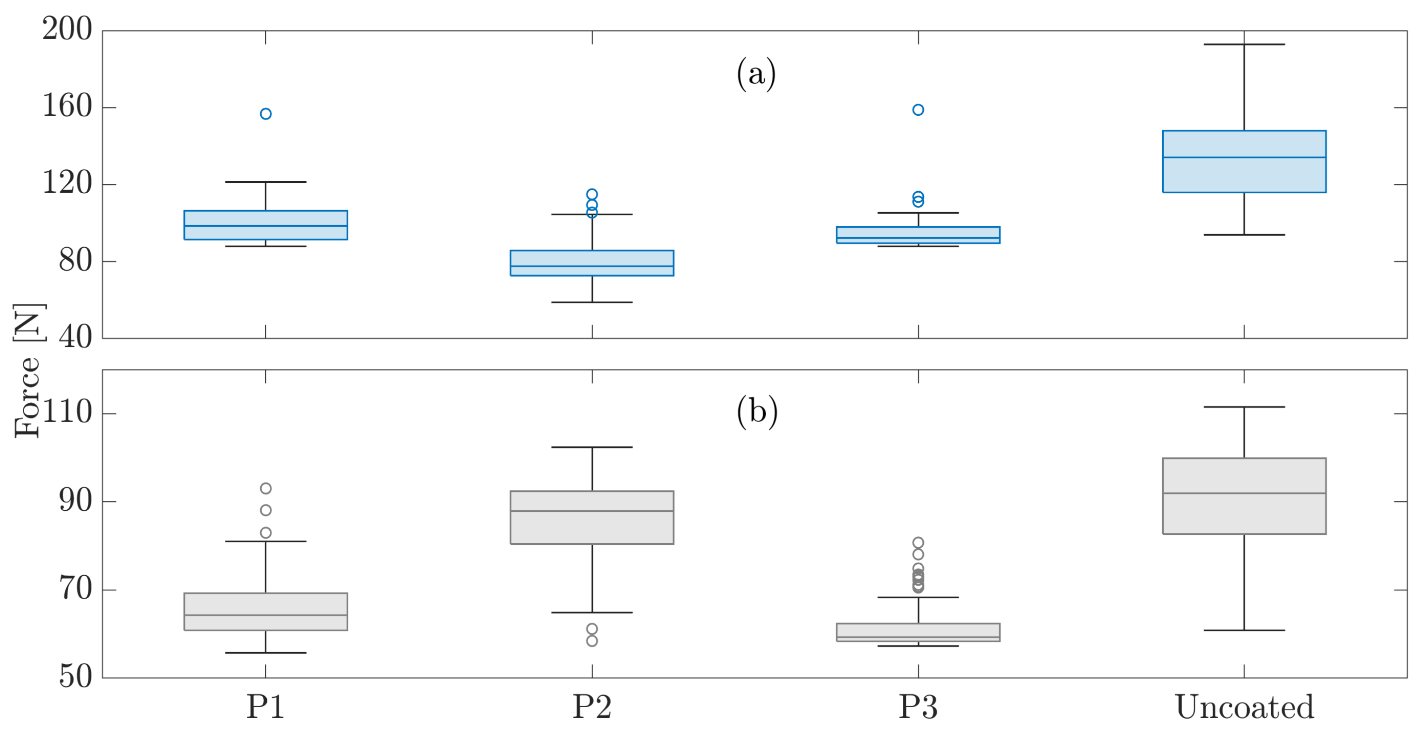
Figure 11 shows some box plots summarizing the gripping forces with each tested material. These plots display the interquartile ranges (IQRs) of the distributions, along with their median, maximum, and minimum values, whereas the outliers are represented by circular markers. The top subplot (a) shows a significant case, i.e., 1000 rpm impact velocity and 2.5 A tightening current (as shown in
Figure 10). These represent the maximum current and velocity.
All the fabrics appeared to result in a smaller gripping force dispersion. The box plot for the uncoated fingers has an IQR of 31.9 N, which is more than double that of P1 with an IQR of 15 N and P2 with an IQR of 12.92 N. As can be seen from
Figure 10, the best-performing fabric seems to be P3 with an IQR of 8.39 N. This is confirmed in
Figure 11b, which illustrates the box plots at the same velocity (1000 rpm) but with a lower tightening current (1.5 A). P3 again exhibits a very flat IQR (4.06 N) compared to P1 (8.44 N) and P2 (11.95 N). The bare finger exhibits very high variability (IQR = 17.37 N). These findings may suggest that a lower stiffness value enhances force repeatability.
Therefore, the proposed approach seems to identify P3 as the optimal contact option for optimizing grasping behavior under the defined conditions. To confirm this finding,
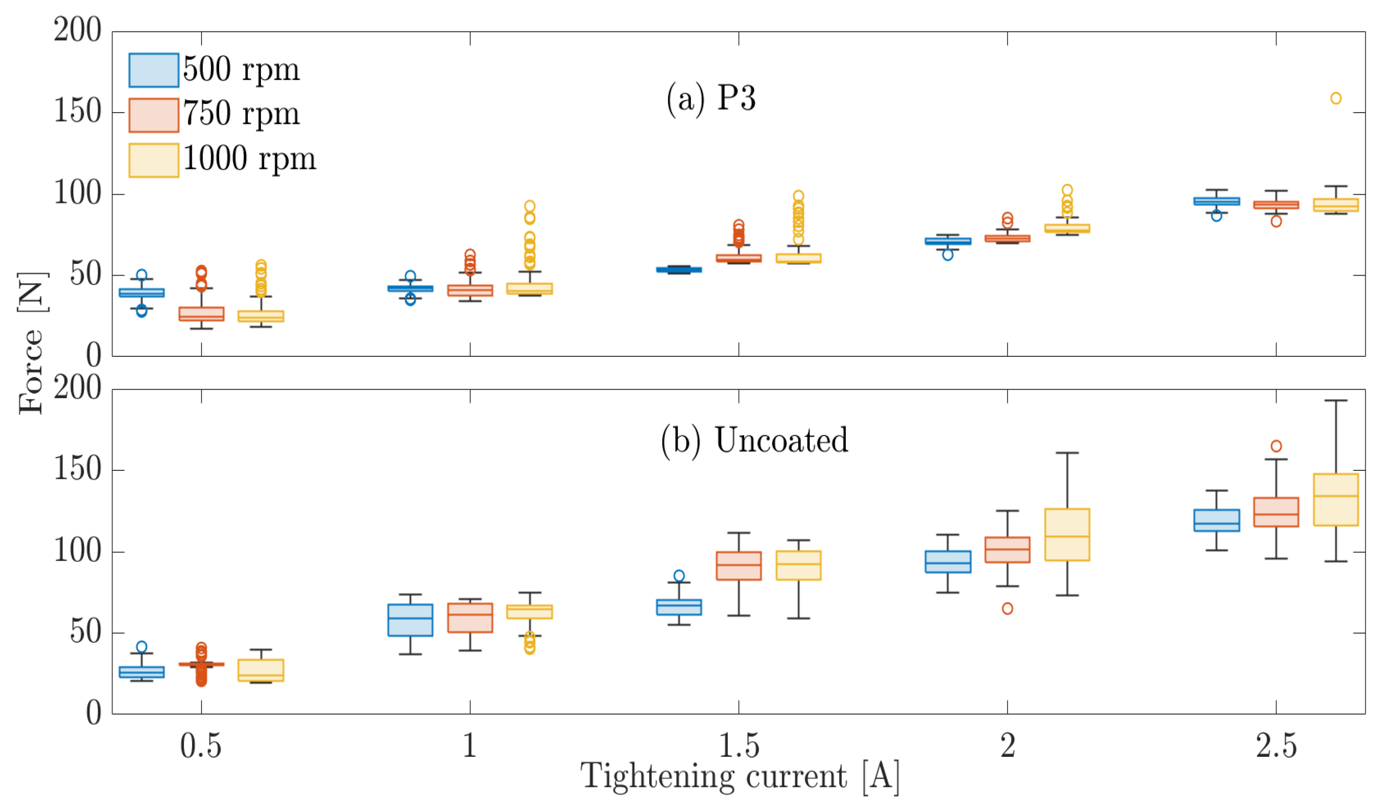
Figure 12 shows a box plot comparison between P3 (a) and uncoated fingers (b) for all the tested impact velocities and tightening currents.
Table 1 summarizes the resulting steady-state force IQRs. Generally, the force IQRs show a significant reduction when using P3 in all conditions. In this regard, bare fingers exhibit superior force dispersion with high-impact velocities and high currents. Moreover, the latter conditions seem to favor unpredictable finger-bouncing dynamics.
The P3 material showed an increasing force trend among the box plots for each velocity, with a clear distinction in force levels at different currents. This is crucial for open-loop architectures. An exception occurred in the case of 500 rpm, where similar force levels were observed at 0.5 A and 1 A.
Outliers were sometimes detected and were often associated with the current peak due to impact. When using P3, the worst case (14%) was 1 A and 1000 rpm. With the bare finger, 24% of outliers were obtained at 750 rpm and 0.5 A.
Finally,
Figure 13 shows a comparison of the simulated and experimental data for the same velocity and current as in
Figure 9, with the addition of P3. This addition reduced the contact stiffness and prevented the risk of grip instability (e.g., object loss), as the force did not drop to zero after the impact force peak. This happened for both the real and simulated curves. The soft coating also evidently helped lower the impact force peak, leading to 160 N instead of 220 N. Indeed, the current peak visible in
Figure 9 was completely eliminated. Furthermore, the steady-state force was 40 N, which is smaller than the 62 N with the bare finger. Both values match the results shown in
Figure 12.
5. Discussion
The proposed approach offers multiple practical advantages for real grasping applications. In particular, this approach (covered by a recent patent application [
20]) is designed for use with grippers equipped with at least two fingers, which are needed for grasping rigid objects with a high force and velocity. A similar scenario is quite common in modern industry.
Robots employed in assembly lines executing, e.g., pick-and-place tasks, need to grasp with the highest possible speed to maximize productivity and duty cycles. Commonly, this requires knowledge of the item’s size [
19]. For instance, the fingers might be commanded to slow down before impact to avoid collisions with excessive velocities and force peaks. In fact, such peaks, especially when rigid objects are to be grasped, might damage the gripper mechanics (e.g., transmission, fingers, motor bearings, etc.). If the velocity and position of the fingers cannot be controlled, as often happens with pneumatic grippers, knowing the size of the object is crucial for designing fingers with specific shapes that help avoid heavy impacts. That is, the finger shape can be conceived to minimize the stroke. Alternatively, it is possible to endow the gripper mechanics, more specifically the transmission, with elastic elements, such as elastomers, which serve to dampen the spurious force peaks that occur at high velocities. This approach is adopted in several commercial grippers produced by well-known manufacturers. However, even considering the most recent and effective grippers (EGU series by Schunk), the maximum linear velocity allowed to grasp objects is limited to 12.5 mm/s per finger (please see
the operating manual).
On the contrary, the proposed method does not require any information on the size of the object to be grasped, while enabling high grasping velocities. Simulations and experiments show that the fingers can safely make contact with objects at high speeds (up to 1000 rpm of motor speed, i.e., 33.5 mm/s of finger motion) by adjusting the mechanical contact properties. This also reduces the overall force variability and avoids finger detachment from the objects, thereby preventing grasp instability and possible slips. Finally, modifying the mechanical properties of the fingers (e.g., through coatings) is much easier than inserting elastic elements in the transmission, also in terms of maintenance.
It is important to note that although velocity control was used in the dynamic experiments, this is not strictly necessary to implement the proposed method. In fact, as shown in
Figure 12, the grasping velocity only has a slight influence on the grasping forces, particularly in the case of P3-coated fingers. This is true at least within the tested velocity range, i.e., 500–1000 rpm (16.5–33.5 mm/s). Clearly, controlling the impact velocity might help further reduce the steady-state force variability. Consequently, electric grippers, more than others, could benefit from this approach since velocity control is generally easier to implement on similar grippers.
Nonetheless, it is fair to recognize some limitations of the proposed method. A continuous comparison between simulated and experimental data, leading to several iterations in terms of both modelization and experiments, may be impractical due to the high effort and time required. For instance, the above process took place when determining the appropriate damping coefficients for finger mechanical contacts. The definition of such contacts requires a more systematic study through dedicated dynamic simulations, avoiding prolonged trial-and-error processes.
Moreover, the proposed approach currently only addresses the grasping of hard items and is more suited for industrial rigid grippers. The authors envisage that additional quantities, such as feedback current and finger acceleration, may be involved in order to target fragile and deformable objects.
6. Conclusions
This article presents a novel, model-based approach to improving the force behavior (reduced peaks and variability) of a robotic gripper when grasping rigid objects. This is achieved by acting on the mechanical properties of the fingers, enabling high-speed grasping of objects of unknown size. No force or torque sensors are required for the gripper operations after the validation of the model output. The approach is based on a direct, continuous comparison between simulated and experimental data. To demonstrate the approach, a robotic gripper was first built according to certain specifications, and then its mathematical model was conceived.
A control architecture based on a velocity-current control switch was designed to drive both the simulations and experiments. The model was initially tested on a static setup, proving its ability to predict actual gripper behavior, involving effects such as hysteresis.
The proposed approach demonstrates that by acting on the mechanical contact properties, e.g., stiffness, the grasping force behavior of robotic grippers can be improved. Three coating polymeric materials, each with a different stiffness, were tested. Coating the metallic fingers led to a drastic reduction in both finger bounces and steady-state force variability. These achievements appear to be a good starting point for the design of open-loop force control strategies that can be implemented in industrial grippers, avoiding the need for grippers with expensive force and/or torque sensors. The reader is invited to find, along with the present article, a video showing some of the described experiments.
Future work will focus on implementing an actual open-loop force control architecture based on the results presented here. These results may also be evaluated in other gripper technologies, e.g., pneumatic, as well as grippers with greater strokes and grasping forces. Further, objects with shapes in addition to flat will be tested, e.g., bottles or cans. Moreover, investigations will be carried out into the reduction of steady-state force outliers, e.g., by optimizing the controller switch logic with faster impact detection. In this way, velocities higher than 33.5 mm/s can be evaluated.


