
Tractor-Robot Cooperation: A Heterogeneous Leader-Follower Approach


The Norwegian Institute of Bioeconomy Research (NIBIO), Center for Precision Agriculture, Nylinna 226, 2849 Kapp, Norway
Robotics 2023, 12(2), 57; https://doi.org/10.3390/robotics12020057
Submission received: 28 February 2023
/
Revised: 30 March 2023
/
Accepted: 3 April 2023
/
Published: 6 April 2023
(This article belongs to the Special Issue Robotics and AI for Precision Agriculture)
Abstract
:In this paper, we investigated the idea of including mobile robots as complementary machinery to tractors in an agricultural context. The main idea is not to replace the human farmer, but to augment his/her capabilities by deploying mobile robots as assistants in field operations. The scheme is based on a leader–follower approach. The manned tractor is used as a leader, which will be taken as a reference point for a follower. The follower then takes the position of the leader as a target, and follows it in an autonomous manner. This will allow the farmer to multiply the working width by the number of mobile robots deployed during field operations. In this paper, we present a detailed description of the system, the theoretical aspect that allows the robot to autonomously follow the tractor, in addition to the different experimental steps that allowed us to test the system in the field to assess the robustness of the proposed scheme.
1. Introduction
The agricultural sector is facing an ever-growing pressure to produce enough food for an increasing population, while maintaining a low level of environmental impact. The combination of both goals necessitates the inclusion of the latest advances in remote-sensing techniques to collect the data as well as the latest developments in agricultural machinery to mitigate the problems that the world is facing at present regarding having a sufficient food supply for everyone. Adding to this, the aging population in the agricultural sector is another factor that increases the need to look for newer alternatives to the conventional practices.
Robotics and artificial intelligent (AI) systems have contributed to the revolution of industrial processes for decades; however, the agricultural sector is still lagging behind, although it is a vital sector that is the foundation of human beings’ existence. The latest advances in robotics and AI should be gradually included, where these tools first assist the farmers in their daily tasks, before completely replacing them in a farmer-free scenario. The main purpose of this is to provide a solution that can be adopted in the near future, in which the farmer is still in touch with the daily activities of the field operations, and to work within the frame of the current legislation regarding the autonomous operations of robotic platforms, namely, the necessity of having a human supervisor that can take back control of the autonomous robot at all times.
Building upon the idea of using robots to assist farmers in their daily tasks, the cooperative nature of these type of systems needs to be addressed. Inspired mainly from nature (e.g., ants [1]), cooperation in robotic systems has attracted the attention of the mobile robotic research community in recent years, due to the great advantages that can be obtained by deploying multiple robots, where each robot can overcome the limitations of the other robots (perception, calculation abilities, payload, etc). Thus, the efficiency of the mission is increased without the need to have a single, complete, complex mobile robot. Although there is a large amount of related works dealing with the inclusion of mobile robots in an agricultural context [2], there is still a need for more efforts in the direction of cooperative robotic schemes in agriculture [3].
Autonomous navigation for single robots is the basis of any further development of fleet management. In the agricultural context, the authors in [4] present a hybrid approach to improving the autonomous navigation of mobile robots for field operations. The approach combines both geometric and semantic information to create a more comprehensive representation of the environment. By doing so, the method improves the accuracy of robot navigation and reduces the risk of collisions. In [5], the authors used a laser range finder model to allow for the autonomous navigation of a mobile robot in a maize field. The model uses a particle filter algorithm to estimate the position of the robot. The approach is effective in handling the uncertainty associated with the environment and the robot’s motion. In [6], the authors illustrated the development of an autonomous navigation controller for agricultural vehicles. The controller relies on a combination of sensors, including GPS and inertial measurement units, to guide the vehicle. The controller was tested and evaluated in different agricultural scenarios, showing promising results.
The use of different sensors to estimate the surrounding environment status is crucial when navigating in semi-clustered environments; the authors in [7] propose a local motion planner for autonomous navigation in grape yards using a red–green–blue depth (RGB-D) camera-based algorithm and deep learning. The approach combines the RGB-D camera and deep learning to recognize and navigate around obstacles. A light detection and ranging device (lidar) was used in [8] to develop an autonomous navigation system for under-canopy environments.The approach uses a combination of LiDAR and GPS sensors to accurately estimate the position of the robot. In [9], an autonomous navigation scheme of an agricultural robot is presented. The approach combines the global navigation satelite system (GNSS), real-time kinematic (RTK) and a Pixhawk [10] to improve the accuracy and reliability of the robot’s navigation. Another interesting work on autonomous navigation in an agricultural context can be found in [11]. The authors present an autonomous navigation system for agricultural machinery based on Linux-ARM technology. The system combines different sensors, including GNSS, compass, and gyroscope, to accurately guide the machinery. In [12], the authors developed a small-scale agricultural mobile robot prototype named Helvis for precision agriculture. The robot is designed to navigate autonomously in agricultural fields, collect data, and perform targeted agricultural tasks such as spraying or fertilizing. The authors in [13] discuss the development of a spraying robot designed for precision agriculture. This robot utilizes an edge-following approach to navigate through crop fields and apply pesticides with accuracy. The edge-following approach allows for the robot to adjust its path based on the irregular shape of crop fields.Equipped with sensors and a control system, the robot is capable of autonomously navigating through fields and applying pesticides with precision.
The recent advances in agricultural robots, whether in navigation, sensing, or overall scheme, have paved the way for the inclusion of multi-vehicles in the same field. The authors in [14] present a simulation environment for fleets of robots used in precision agriculture. The simulation environment allows for the testing and optimization of various fleet configurations and control algorithms. In [15], the authors describe a method used to assign tasks and planning trajectories for a group of cooperative agricultural robots. The method uses a combination of a genetic algorithm (GA) and multi-agent system (MAS) to optimize task assignments and trajectories for the robots. The proposed method was tested using simulated scenarios, and the results showed that it is able to effectively assign tasks and plan trajectories for the robots, which leads to an increase in the efficiency of the overall task performance. In [16] a multi-robot tractor system was designed and developed for use in agriculture field work. The system consists of multiple tractors that are capable of working together to perform tasks such as plowing, planting, and harvesting. The tractors are equipped with sensors and communication devices to enable them to coordinate their actions and share information. The system is designed to improve the efficiency of agricultural field work by allowing multiple tractors to work together to complete tasks. The authors of the paper have implemented and tested the system in a simulated environment, and the results show that it is capable of performing tasks effectively and efficiently. The authors in [17] present the development of an automatic navigation system for agricultural machinery. The system is designed to guide agricultural machinery, such as tractors and harvesters, along a predefined path without the need for human intervention. The proposed system uses a combination of GPS, inertial sensors, and machine vision to determine the position and orientation of the vehicle and to track the path to be followed. Communication is key to successful multi-vehicle navigation; the authors in [18] describe the development of a multi-vehicle cooperative navigation communication system based on TD-LTE. The system uses a combination of GPS and TD-LTE to achieve high-precision positioning, communication, and data transmission between vehicles. The system was tested in an agricultural field, focusing on evaluating the latency of the communication scheme. Precise pose estimation is another key to achieving desirable behavior when driving in the field; the authors in [19] proposed an integrated navigation system for agricultural machinery based on RTK-BDS/INS. The system used an RTK-BDS satellite navigation system and an inertial navigation system (INS) for accurate positioning and orientation. The experimental results show that the proposed system has good positioning accuracy and stability, making it suitable for agricultural machinery applications. The authors in [20] developed a leader–follower structure for harvesting purposes.This approach allows the group to navigate efficiently and effectively, particularly in challenging environments. The work in [21] proposes an approach to multi-vehicle navigation based on a dynamic inter-target distance matrix, which provides a stable and flexible solution for complex scenarios. The method combines centralized and decentralized control approaches to optimize the navigation task. The simulation results show that the proposed method achieved a better performance in terms of stability and flexibility compared to traditional methods. In [22], the authors present a method for controlling the formation of a group of agricultural mobile robots. The method uses a bidirectional weighted constraints approach, which allows for the robots to maintain a specific formation while also considering obstacles and other constraints in the environment. The proposed method was tested using simulations and experiments with real robots, and the results showed that it is able to effectively control the formation of the robots while also maintaining safety and avoiding collisions. A leader–follower tracking system was presented in [23]. The system allows for a lead vehicle to be followed by one or more follower vehicles, with the aim of improving the efficiency of agricultural field work. The system is based on a combination of a control algorithm and a communication system to enable the vehicles to track the lead vehicle and maintain a safe distance. The authors of the paper have implemented and tested the system in a simulated environment, and the results have shown that it is capable of effectively tracking the lead vehicle and maintaining a safe distance between the vehicles.
Although interesting, most of the related works assessed using simulated experiments, which limits the applicability of the proposed schemes in real-life conditions, especially when it comes to communication issues, controller design, navigation on uneven terrains, and the cooperative aspects of fleet navigation. In this paper, we cover the aforementioned aspects by taking the inclusion of a mobile robot alongside a conventional tractor as an example, and present the theoretical aspects, as well as the experimental results that were achieved in the fields of our research station, located in Kapp, Norway.
The rest of the paper is organized as follows: in Section 2 we provide a description of the different elements of the system. In Section 3, we present the control laws that allow for autonomous navigation inside the field to fulfill the leader–follower scheme requirements. In Section 4, we show the experiments that were preformed, followed by a discussion to assess the robustness of the proposed method. In Section 5, we conclude the paper and provide some guidelines regarding future possibilities to enhance the overall cooperation approach.
2. Materials and Methods
Hardware Description
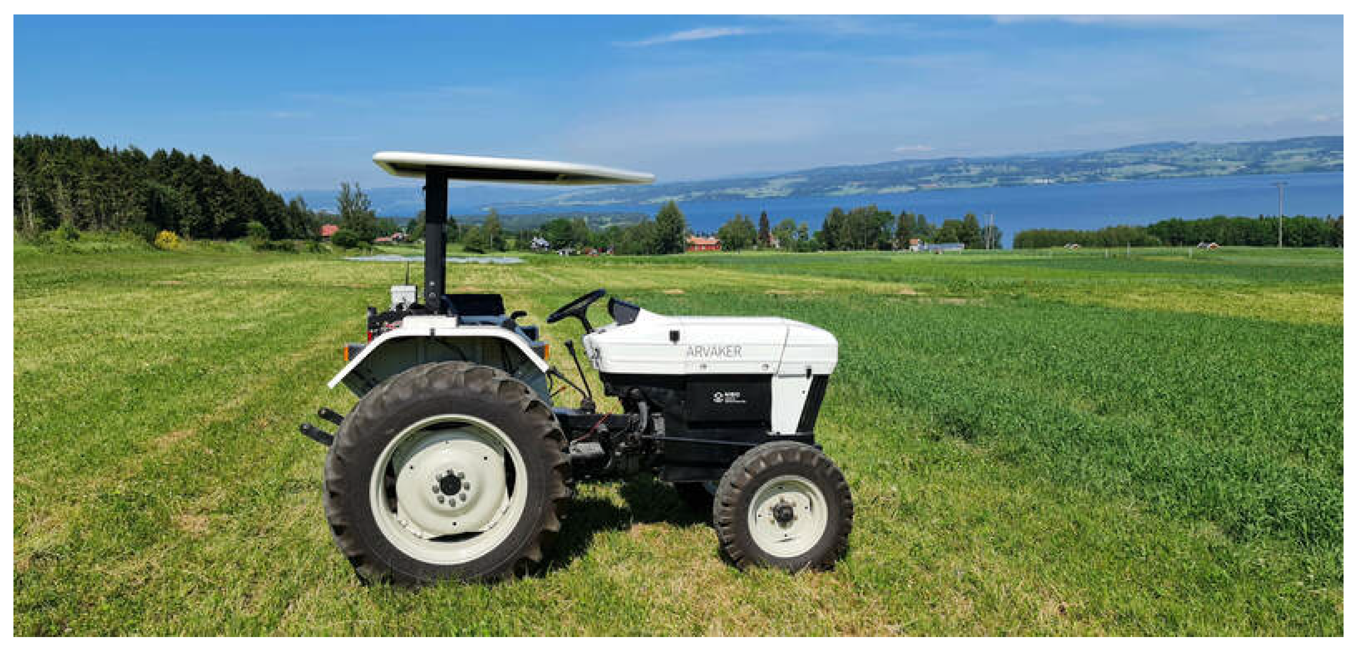
The study-case that we are describing in this paper utilizes an electrical tractor (manned, leader) and an electrical robot-tractor (unmanned, follower). The tractor (Solectrac, CA, USA [24]) is powered by a 48 V lithium-ion battery with a capacity of 30 kWh. It can be fully charged in 7–8 h using a 240 v/30 A charger. The electric motor is a 48 V PM brushless type with a continuous output of 25 horsepower and a peak output of 50 horsepower. The tractor’s chassis is based on the Ford 7610 2001 model (Figure 1).
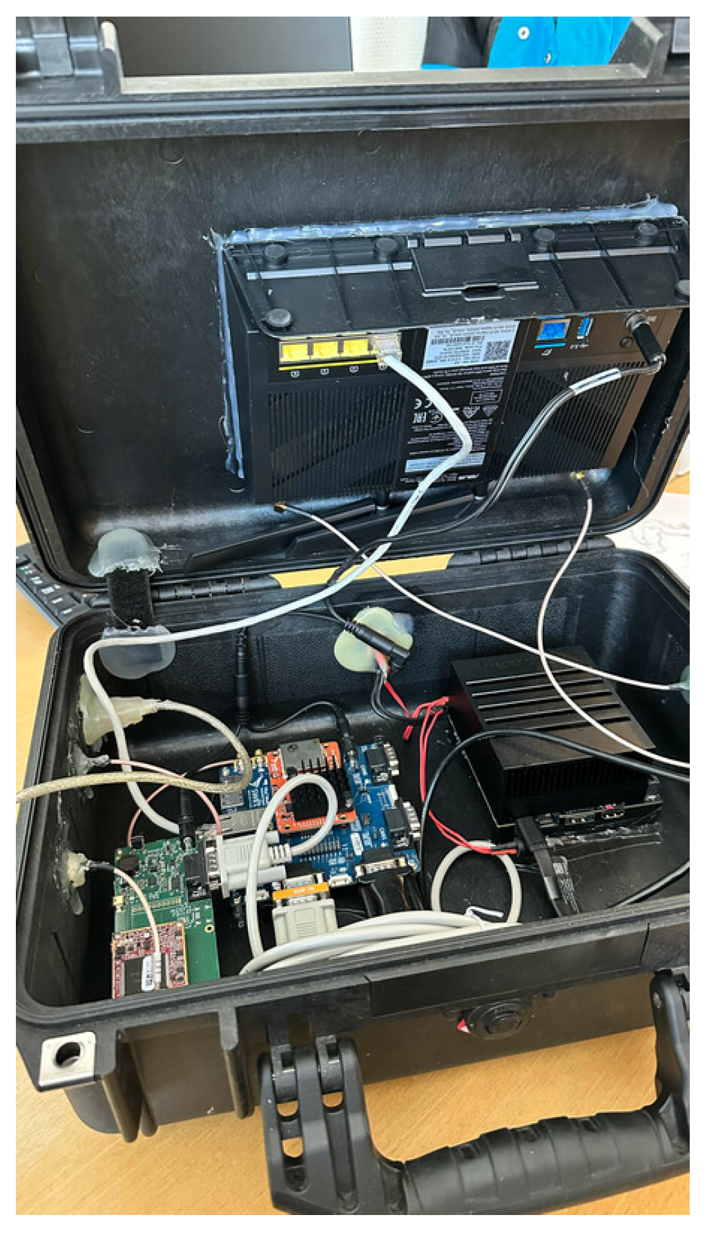
To obtain an accurate pose estimation (position and heading) of the tractor, we equipped it with a high-resolution lobal navigation satellite system (GNSS) receiver and a real-time kinematic (RTK) module (Piksi Multi Evaluation kit, SwiftNav, CA, USA [25]), and a high-precision inertial measurement unit (IMU) (VN-100, Vectornav, TX, USA [26]). The pose estimation was performed on an embedded computer (Jetson AGX Xavier, Nvidia, CA, USA [27]) running Ubuntu 20.04 LTS and the robot operating system (ROS Noetic) [28]. The results of the pose estimation were broadcast to the robot through wireless user datagram protocol (UDP) packages via the installed wireless router (Asus 4G-AC68U, ASUS, Taipei, Taiwan [29]). Figure 2 illustrates the hosting case for the tractor’s embedded computer, GNSS-RTK board, and the wireless router.
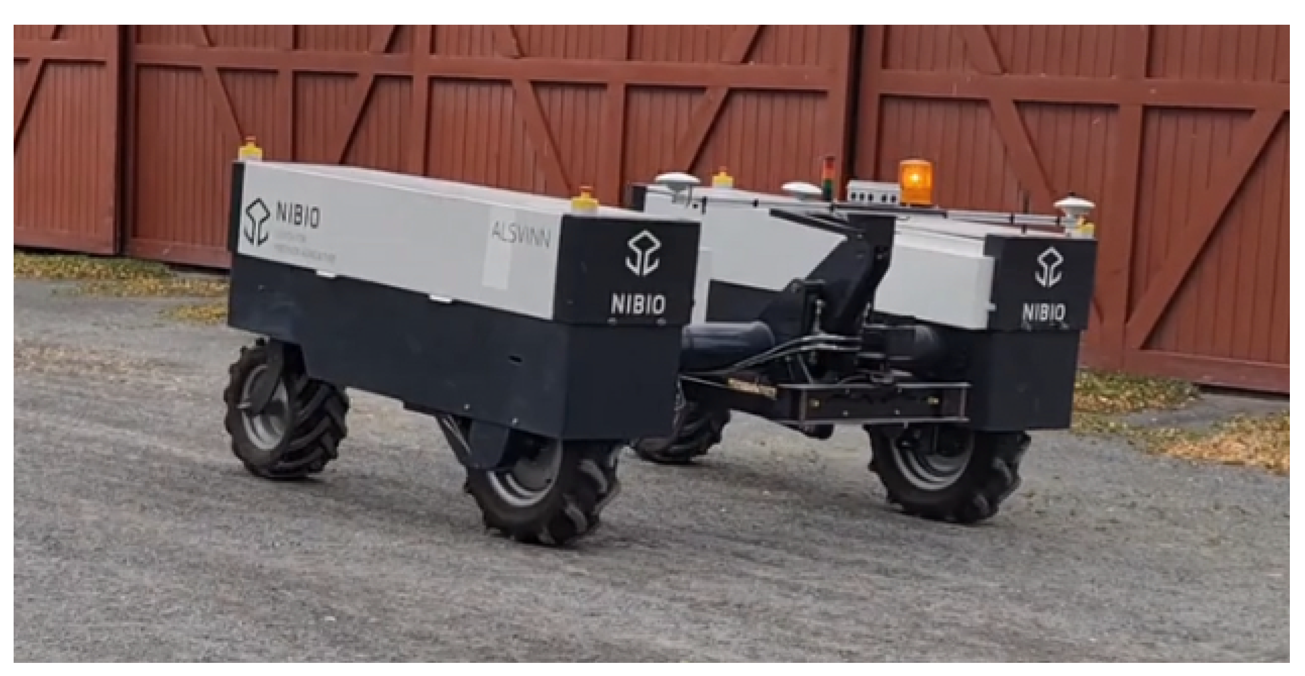
The mobile robot (referred to as “robot” in the remainder of the paper) is a differential drive vehicle (Figure 3) with a payload of maximum 750 kg. It is equipped with a three-point mount system similar to the one used by conventional tractors, which opens for a multi-purpose utilization. Eight (8) 12 V batteries power the robot. We redesigned the robot to meet our requirements. The driving wheels and their gearbox have were upgraded, and all the electronic parts were remade. The robot was run on ROS (Noetic) and equipped with the same RTK-GNSS receiver as in the one found on the tractor.
Table 1 illustrates the different technical specifications of the robot:
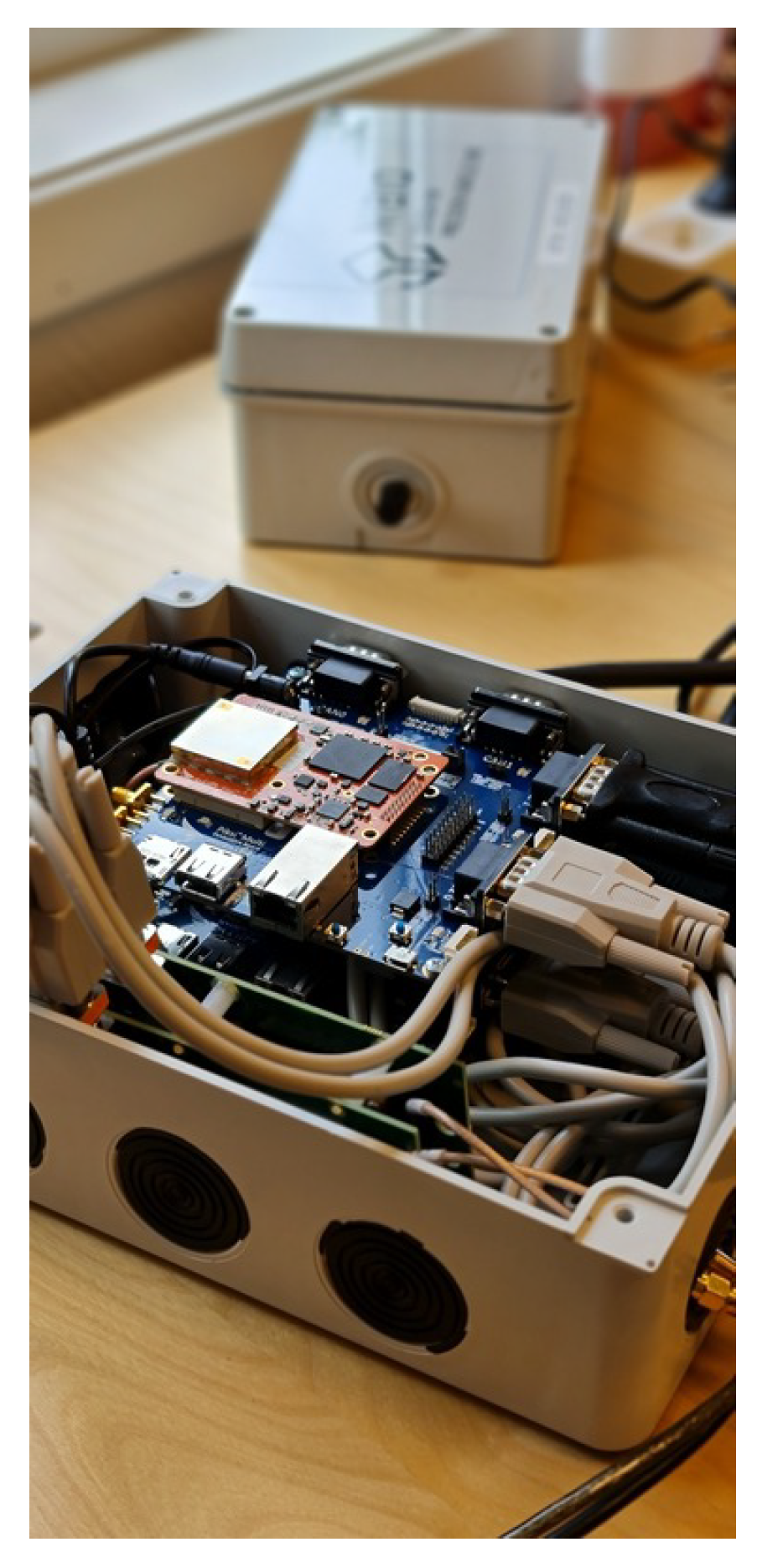
We initially relied on the onboard IMU of the robot to obtain the heading estimation; however, the data were not reliable and the drift was too big to be used as a reliable source for the autonomous navigation. To this end, we equipped the robot with two additional GNSS-RTK receivers (Figure 4) in order to obtain a more robust heading estimation with no drift over time.
3. Leader–Follower Scheme
Regardless of the domain of application, the inclusion of a human supervisor is necessary when dealing with autonomous robots [30] in real conditions. The main purpose of the present study is to propose a scheme that can be applied in the near future, even with the current regulations. The farmer will have access to the controlling unit of the robot at all times and, in the case of an incident, can take back control of the robot or halt its operations. With these constraints in mind, the field operations will be performed as a team composed of a leader (the manned tractor) and a follower (the robot).
The tractor is driven in a conventional way (moving from one row to another during field operations). As the leader (tractor) navigates inside the field, the follower takes the leader as a target and follows it, maintaining a predefined configuration; this allows the working width inside the field to be doubled with only one manned vehicle. In [31], we presented a leader–follower scheme for multi-vehicle navigation, where the leader was taken as a visual reference to the followers, and the group performed object transportation in an industrial context. Building on that work, in this paper we replaced the visual referencing aspects with a direct communication scheme which allowed for a more robust navigation, especially in outdoor environments, where the efficiency of vision can easily be reduced or even obstructed by natural elements.
Control Law Design
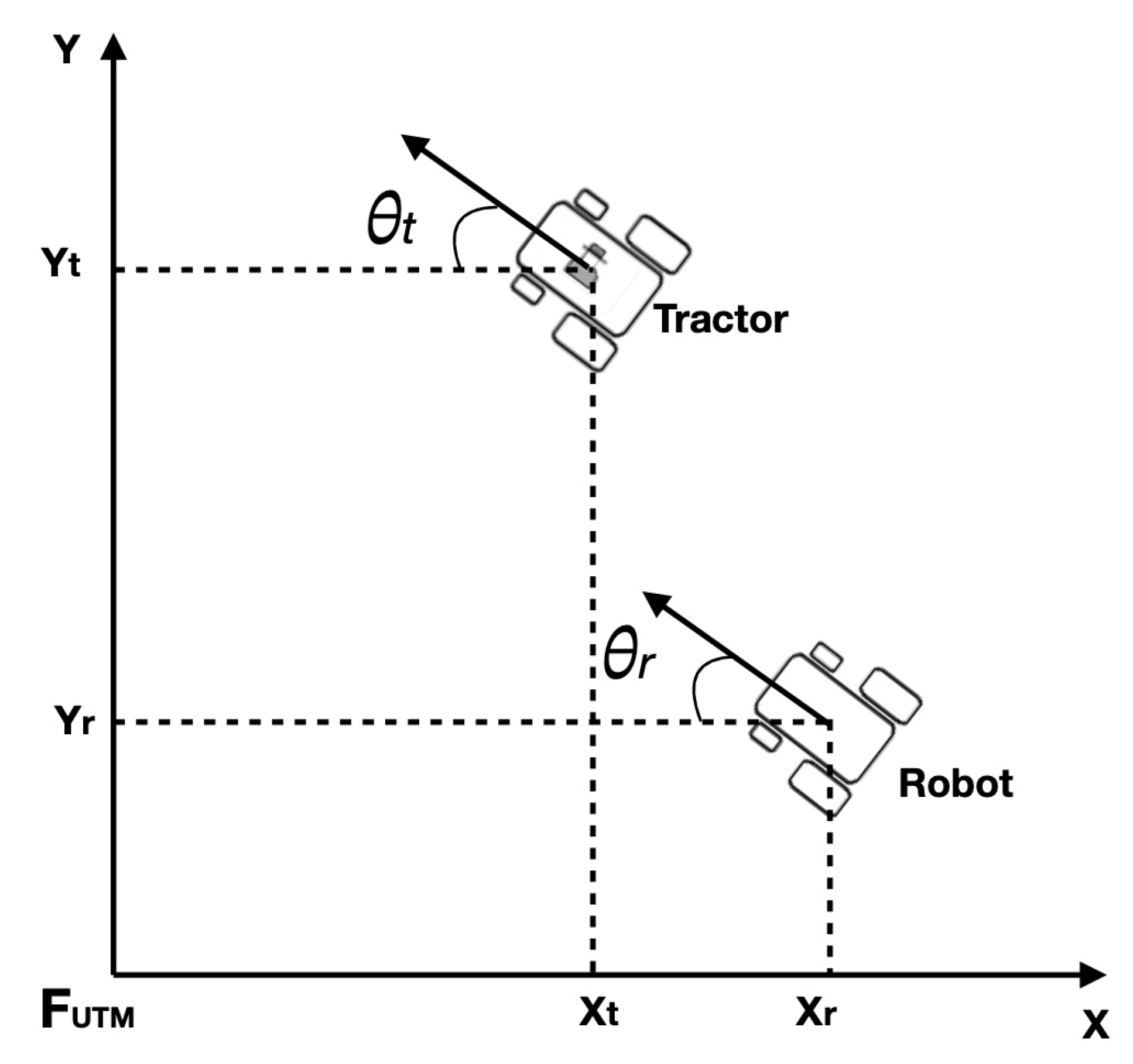
Autonomous fleet navigation in a leader–follower configuration suggests that the robot can take a reference point to the position of the tractor as the following target and follow it in an autonomous manner (Figure 5). To this end, the controller of the robot has to generate both the linear v and angular w velocities, which ensure that the error between the position of the robot and the tractor is reduced to the predefined values.
The reference frame of both the tractor and robot is represented in the universal transverse mercator (UTM) coordinates. We denote as the reference frame where the planar navigation of the tractor and the robot occurred. The formation shape for the field navigation was decided prior to the mission, combining both the distance that separates the tractor from the robot and the side on which the farmer desires the robot to follow (right or left). The main objective of the control law is to ensure that the robot is navigating at the desired side, while holding the predefined distance at acceptable lower boundaries.
We consider the following errors along the X and Y axis in the reference frame . They represent the difference between the actual robot pose, and the reference pose of the desired configuration:
where and represent the UTM coordinates of the reference point of the tractor, while and are the UTM coordinates of the robot. and represent the heading of the tractor and the robot in the reference frame, respectively .
The aim of the controller is to regulate the distance and the angle that separate the robot from the reference point as follows:
In Equation (2), the desired position of the reference point is defined by the polar coordinates (, ). represents the predefined linear distance that separates the robot and tractor. represents the predefined bearing angle that is selected according to the following mode. In our experiments, if we want the robot to follow the tractor from a position that is considered to be south-east to the position of the tractor, or if we want the robot to follow the tractor from a position that is considered to be south-west to the position of the tractor.
From Equation (1), the error representation of both the distance and the angle are directly linked to the linear v and angular w velocities of the robot. To ensure that the conditions in Equation (2) are fulfilled, we propose the following non-linear controller that considers these errors and the required velocities:
where , , and are positive gains.
4. Experimental Results
4.1. Static GNSS Waypoint Following
The tuning of the positive gains in Equation (3) was carried out manually. The tractor was parked so the broadcasted pose to the tractor was considered a static waypoint (this could have been replaced by providing a static GNSS waypoint, but we wanted to test the communication robustness before performing the field navigation). The process is as follows: each time the robot was driven manually to a random location, we switched on the autonomous navigation and let the robot navigate to the reference point while observing its behavior. Once the robot reached the reference location, the gains were tuned and the process was repeated (drive the robot to a different starting point, etc.).
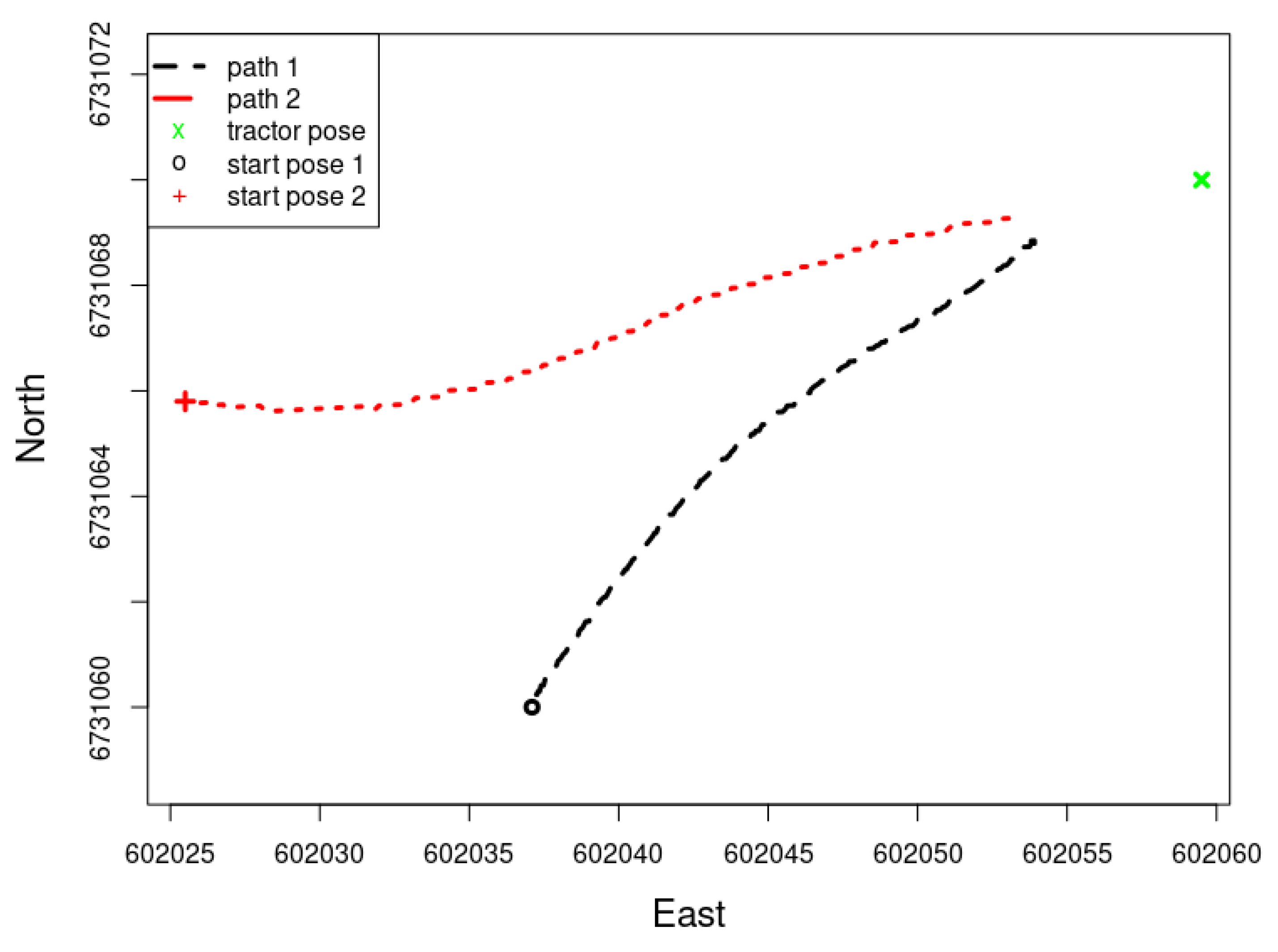
In Figure 6, two examples of the tests performed to finetune the positive gains of the control law are presented (Equation (3)). The robot has two different starting values (in UTM coordinates): start pose 1 (602,037.1 North, 6,731,060 East), and start pose 2 (602,025.5 North, 6,731,065.8 East).
The robot used the pose of the tractor as the following goal, and tried to reduce the pose errors (Equation (2)) to the predefined values. The gains were then tuned to reduce the undesired behavior of the robot while driving and reduce the converging time to the desired pose (tractor location). The trajectory of the robot during these trials (starting positions 1 and 2) can be seen in Figure 7.
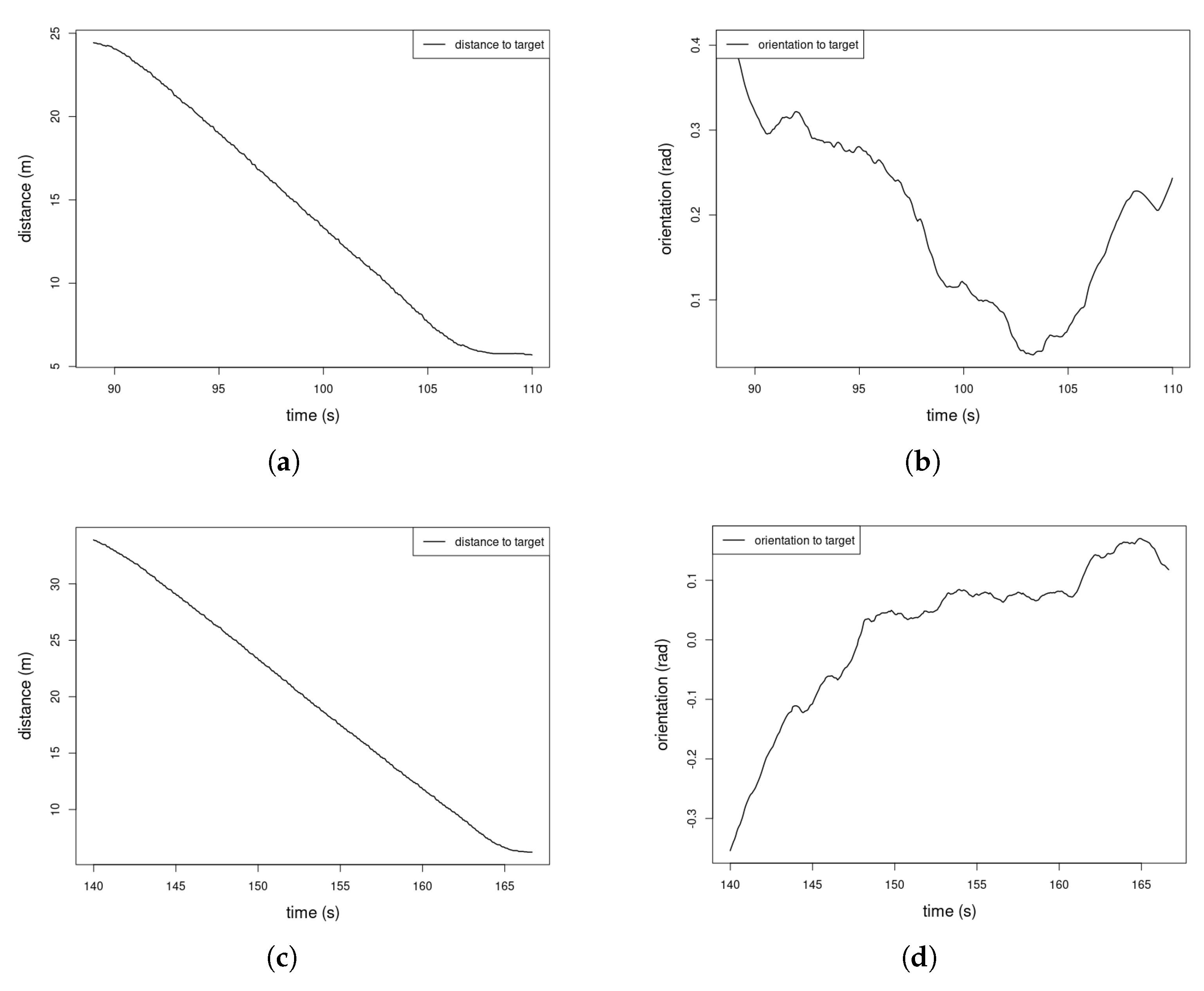
The distance and orientation of the robot to the tractor’s pose were recorded in order to assess the evolution of the errors of both the distance and the angle (Figure 8).
We can see from Figure 8 that, during the first example of the navigation from starting position 1, the distance shown in Figure 8a converged to the desired pose from the tractor (7 m from the back of the tractor); however, we can see from Figure 8b that the orientation is not stable. The second starting point was initiated after adjusting the gains of the controller and, this time, we can see that both the distance (Figure 8c) and orientation (Figure 8d) converged more smoothly to the desired values.
4.2. Dynammic GNSS Waypoint Following: Leader–Follower Configuration
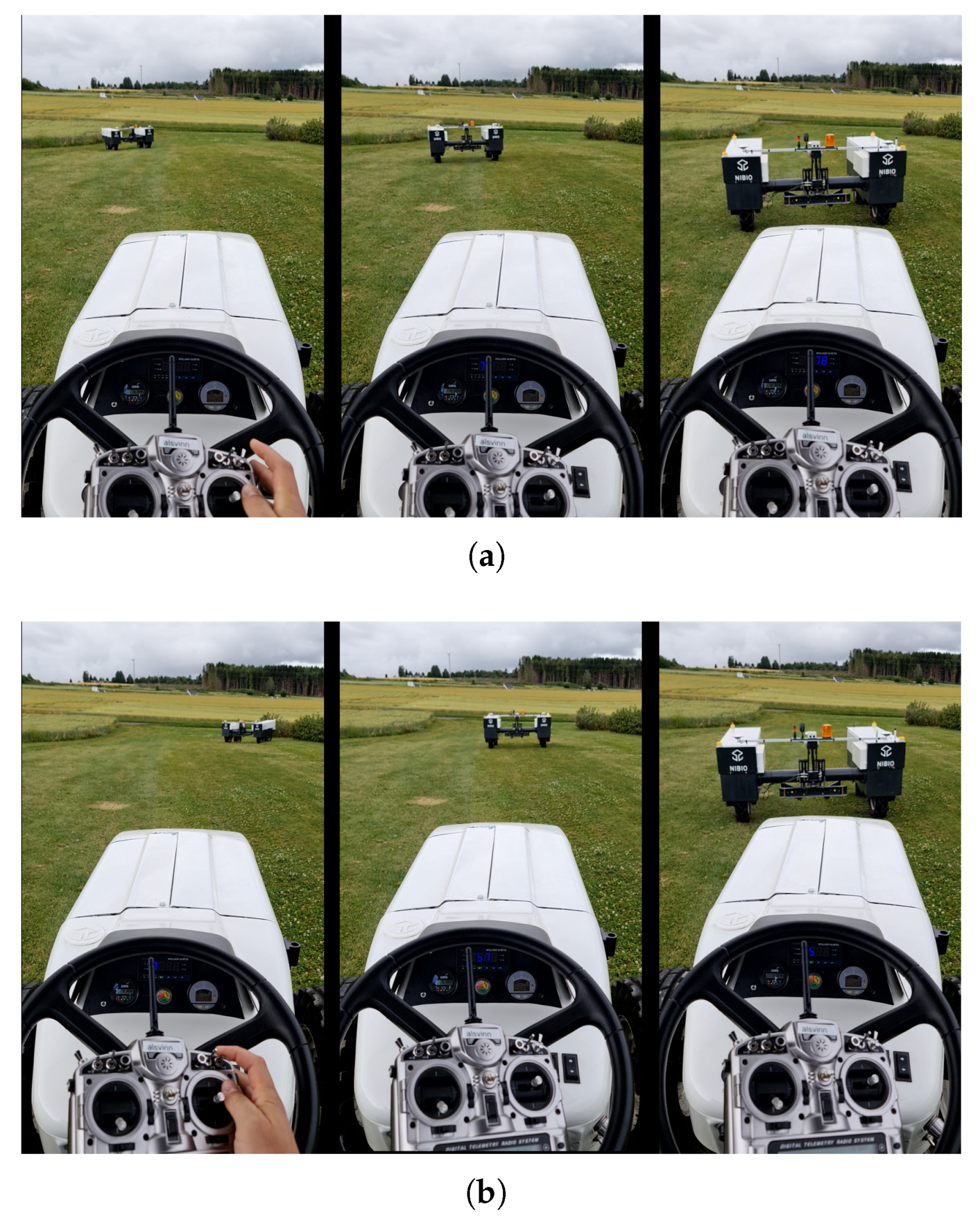
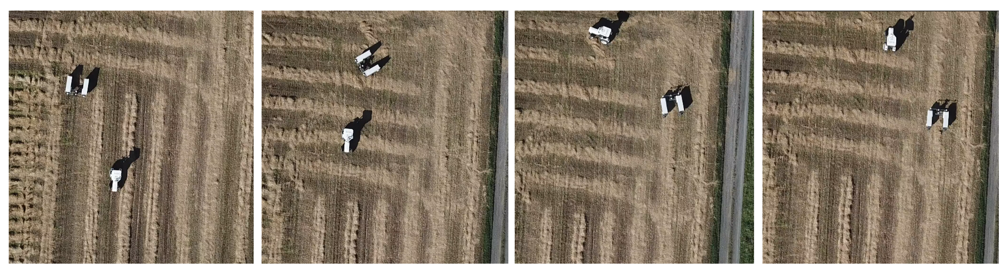
Once we ensured that the robot showed acceptable behavior when navigating towards the fixed location of the tractor, we moved to the second phase. We performed field driving, where the tractor’s pose is no longer static, but dynamic. To this end, the tractor was driven manually throughout the field while broadcasting its position continuously to the robot. The robot, taking the tractor’s pose as a target, used the control law established in Equation (3) to reduce both the distance and the angle and fulfill the predefined configuration (driving to the right of the tractor at a distance of 7 m). Figure 9 illustrates a sequence where the tractor and robot performs a U turn while driving inside the field.
The aim of this experiment was to demonstrate the fleet navigation scheme inside the field. The tractor and the robot were both connected to same subnet via the wireless router, which was mounted on the the tractor. The tractor broadcast its position and heading continuously as UDP packeted. The robot listened to these packets and extracted the necessary linear and angular velocities that reduce both the distance and the angle that separates its current position from the desired following position. We performed several driving rounds in order to assess the robustness of both the communication scheme and the control law of the robot.
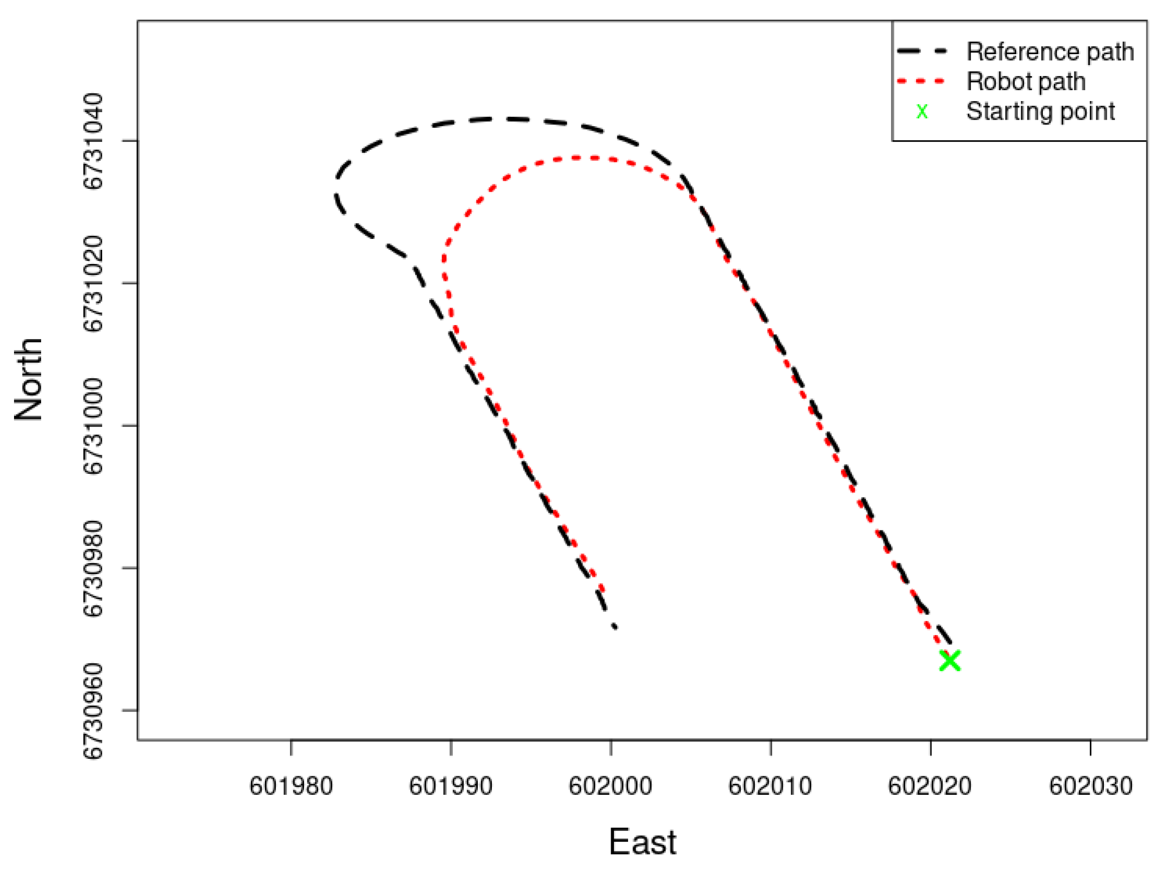
As the tractor directly sent the coordinates of the reference point (and not its own coordinates), the robot only had access to reference point coordinates and not the actual coordinates of the tractor. Since we only recorded the data from the robot, we only had the reference path (the evolution of the reference point during the navigation) and not the actual path of the tractor. Figure 10 shows the path of the robot and its reference path while navigating inside the field.
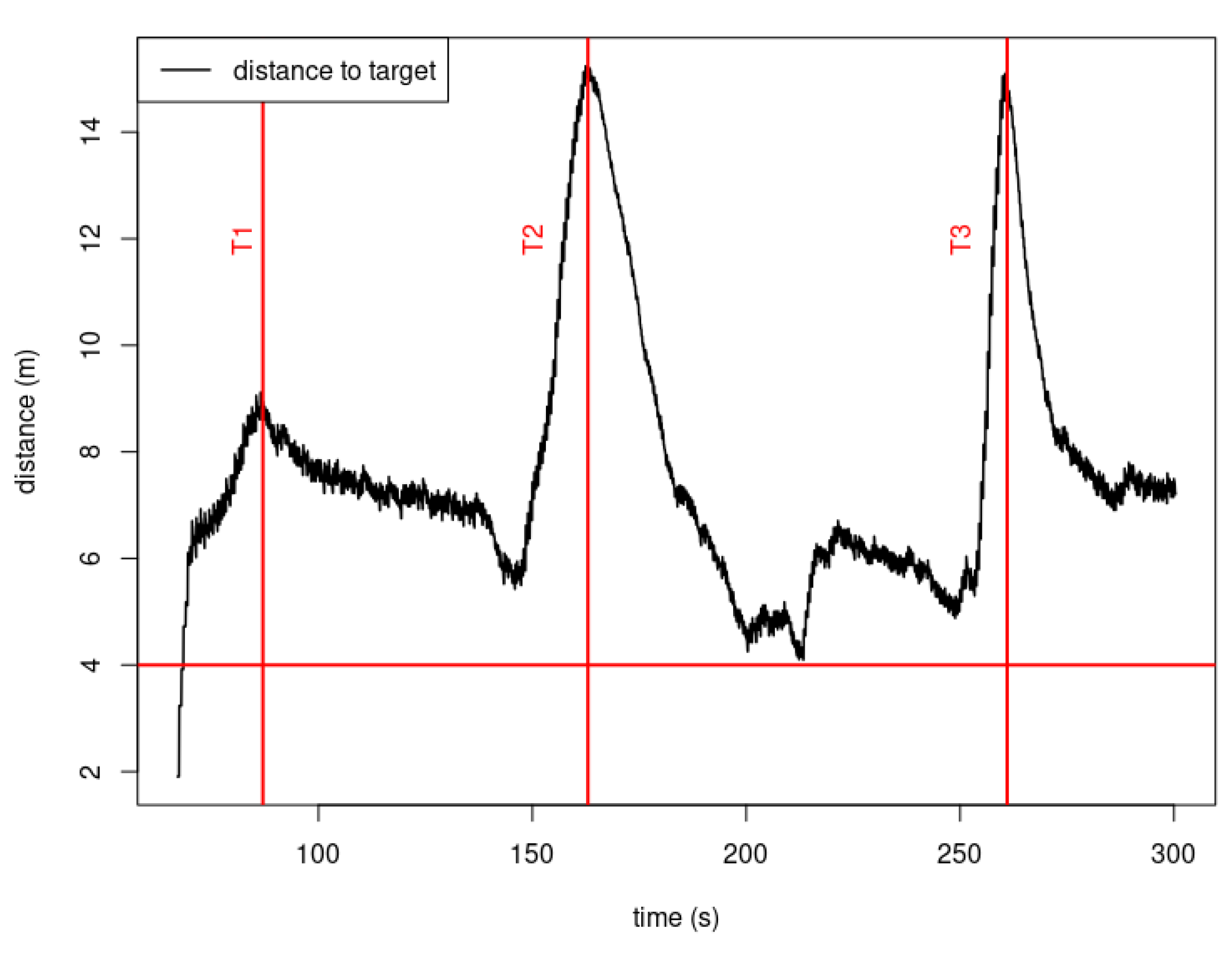
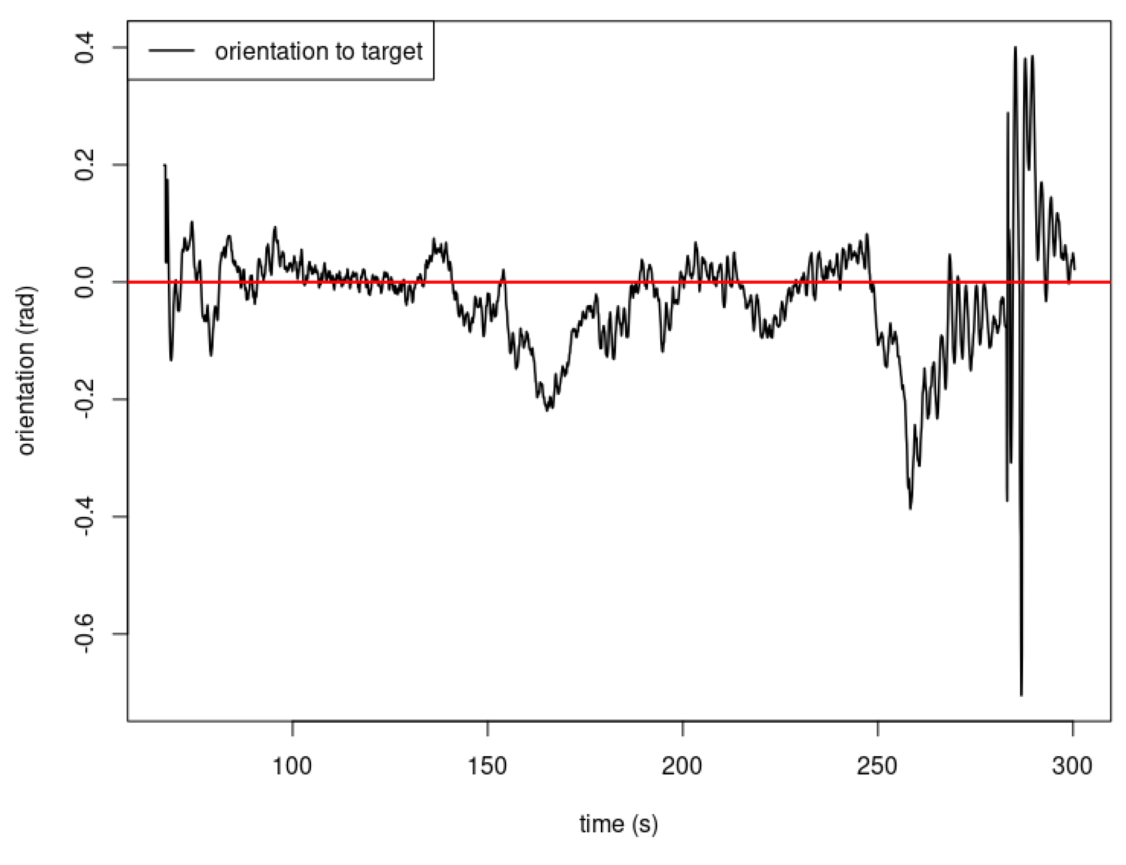
During field navigation, the tractor was driven without using cruise control for constant speed, and the navigation trajectory was chosen to emulate driving back and forth with U-turns in between. Figure 11 and Figure 12 show, at T1 = 87 s, T2 = 163 s, and T3 = 261 s, spikes in the distance that separates the robot from the tractor. These occurred when the tractor driver performed a u-turn (the spikes are the turning point at which the tractor’s driver is already performing the other half of the u-turn). Since the robot, at the time of writing this paper, has no special instructions when it comes to performing u-turns, the distance that separates it from the tractor increases because of the upper-velocity limit that imposed on the motors’ speed controllers for security reasons. At the end of the previously mentioned time spikes (t1, t2, t3), we can see that the distance converges again, which means that the robot is caught up with tractor, and followed it according to the predefined scheme.
The experimental results, whether following a static waypoint or driving in the field in a leader–follower scheme, state that the developed controller in this paper is able to satisfy the control objective (Equation (2)). However, we believe that adding some filtering functions [32] could contribute to achieving a much smoother navigation scheme and more efficient following of the robot.
5. Conclusions
In this paper, we presented a leader–follower scheme for an agricultural use-case. A tractor and a robot were used to demonstrate the ability of multi-vehicle cooperation in field tasks. The tractor was manned and driven manually, while the robot was unmanned and completely autonomous. The scheme relies on direct communication between the tractor and the robot, which allows for the continuous broadcasting of the pose of the tractor (position and heading) to the robot. The robot uses this information as input and follows the tractor in a predefined configuration. In this paper, we developed the necessary hardware and software (communication and control scheme) to allow the robot to fulfill this task and experimentally showed the viability of the proposed scheme. The work presented in this paper can be extended to include multiple followers, and a future direction may be the inclusion of more robots, developing the necessary layers to deal with navigation inside the field, and the management of the different tasks, such as reconfiguration, charging, and failure-proofing.
Funding
The work presented in this paper was part of the project SOLARFARM, funded by the Norwegian Research Council (program “Lavutslipp 2030”, project no. 280390).
Data Availability Statement
The data presented in this study are available on request from the corresponding author.
Conflicts of Interest
The author declares no conflict of interest.
References
- Guinand, F.; Monmarche, N.; Siarry, P. Artificial Ants: From Collective Intelligence to Real-Life Optimization and Beyond; ISTE: London, UK, 2010. [Google Scholar]
- Thomasson, J.A.; Baillie, C.P.; Antille, D.L.; McCarthy, C.L.; Lobsey, C.R. A review of the state of the art in agricultural automation. Part II: On-farm agricultural communications and connectivity. In Proceedings of the 2018 ASABE Annual International Meeting. American Society of Agricultural and Biological Engineers, Detroit, MI, USA, 29 July–1 August 2018; p. 1. [Google Scholar]
- Lytridis, C.; Kaburlasos, V.G.; Pachidis, T.; Manios, M.; Vrochidou, E.; Kalampokas, T.; Chatzistamatis, S. An overview of cooperative robotics in agriculture. Agronomy 2021, 11, 1818. [Google Scholar] [CrossRef]
- Emmi, L.; Le Flécher, E.; Cadenat, V.; Devy, M. A hybrid representation of the environment to improve autonomous navigation of mobile robots in agriculture. Precis. Agric. 2021, 22, 524–549. [Google Scholar] [CrossRef]
- Hiremath, S.A.; Van Der Heijden, G.W.; Van Evert, F.K.; Stein, A.; Ter Braak, C.J. Laser range finder model for autonomous navigation of a robot in a maize field using a particle filter. Comput. Electron. Agric. 2014, 100, 41–50. [Google Scholar] [CrossRef]
- Yin, X.; Wang, Y.; Chen, Y.; Jin, C.; Du, J. Development of autonomous navigation controller for agricultural vehicles. Int. J. Agric. Biol. Eng. 2020, 13, 70–76. [Google Scholar] [CrossRef]
- Aghi, D.; Mazzia, V.; Chiaberge, M. Local motion planner for autonomous navigation in vineyards with a RGB-D camera-based algorithm and deep learning synergy. Machines 2020, 8, 27. [Google Scholar] [CrossRef]
- Higuti, V.A.; Velasquez, A.E.; Magalhaes, D.V.; Becker, M.; Chowdhary, G. Under canopy light detection and ranging-based autonomous navigation. J. Field Robot. 2019, 36, 547–567. [Google Scholar] [CrossRef]
- Moeller, R.; Deemyad, T.; Sebastian, A. Autonomous navigation of an agricultural robot using RTK GPS and Pixhawk. In Proceedings of the 2020 Intermountain Engineering, Technology and Computing (IETC), Orem, UT, USA, 2–3 October 2020; pp. 1–6. [Google Scholar]
- Pixhawk Open Standards for Drone Hardware. Available online: https://pixhawk.org/ (accessed on 1 February 2023).
- Wang, M.; Tang, Y.; Hao, H.; Hao, F.; Ma, J. The design of agricultural machinery autonomous navigation system based on Linux-ARM. In Proceedings of the 2016 IEEE Advanced Information Management, Communicates, Electronic and Automation Control Conference (IMCEC), Xi’an, China, 3–5 October 2016; pp. 1279–1282. [Google Scholar]
- Velasquez, A.; Higuti, V.; Guerrero, H.; Milori, D.; Magalhães, D.; Becker, M. Helvis-a small-scale agricultural mobile robot prototype for precision agriculture. In Proceedings of the 13th International Conference of Precision Agriculture, International Society of Precision Agriculture, St. Louis, MO, USA, 31 July–3 August 2016; Volume 17. [Google Scholar]
- Danton, A.; Roux, J.C.; Dance, B.; Cariou, C.; Lenain, R. Development of a spraying robot for precision agriculture: An edge following approach. In Proceedings of the 2020 IEEE Conference on Control Technology and Applications (CCTA), Montreal, QC, Canada, 24–26 August2020; pp. 267–272. [Google Scholar]
- Emmi, L.; Paredes-Madrid, L.; Ribeiro, A.; Pajares, G.; Gonzalez-de Santos, P. Fleets of robots for precision agriculture: A simulation environment. Ind. Robot. Int. J. 2013, 40, 41–58. [Google Scholar] [CrossRef]
- Li, N.; Remeikas, C.; Xu, Y.; Jayasuriya, S.; Ehsani, R. Task assignment and trajectory planning algorithm for a class of cooperative agricultural robots. J. Dyn. Syst. Meas. Control 2015, 137, 051004. [Google Scholar] [CrossRef]
- Zhang, C.; Noguchi, N. Development of a multi-robot tractor system for agriculture field work. Comput. Electron. Agric. 2017, 142, 79–90. [Google Scholar] [CrossRef]
- Li, S.; Xu, H.; Ji, Y.; Cao, R.; Zhang, M.; Li, H. Development of a following agricultural machinery automatic navigation system. Comput. Electron. Agric. 2019, 158, 335–344. [Google Scholar] [CrossRef]
- Shichao, L.; Ruyue, C.; Shuang, W.; Yuhan, J.; Man, Z.; Han, L. Development of multi-vehicle cooperative navigation communication system based on TD-LTE. Nongye Jixie Xuebao/Trans. Chin. Soc. Agric. Mach. 2017, 48, 45–51, 65. [Google Scholar]
- Huang, Y.; Fu, J.; Xu, S.; Han, T.; Liu, Y. Research on Integrated Navigation System of Agricultural Machinery Based on RTK-BDS/INS. Agriculture 2022, 12, 1169. [Google Scholar] [CrossRef]
- Xiaoping, B.; Zhuo, W.; Jingtao, H.; Lei, G.; Feng, X. Harvester group corporative navigation method based on leader-follower structure. Nongye Jixie Xuebao/Trans. Chin. Soc. Agric. Mach. 2017, 48, 14–21. [Google Scholar]
- Vilca, J.; Adouane, L.; Mezouar, Y. Stable and flexible multi-vehicle navigation based on dynamic inter-target distance matrix. IEEE Trans. Intell. Transp. Syst. 2018, 20, 1416–1431. [Google Scholar] [CrossRef]
- Guillet, A.; Lenain, R.; Thuilot, B.; Rousseau, V. Formation control of agricultural mobile robots: A bidirectional weighted constraints approach. J. Field Robot. 2017, 34, 1260–1274. [Google Scholar] [CrossRef]
- Zhang, C.; Noguchi, N. Development of leader-follower system for field work. In Proceedings of the 2015 IEEE/SICE International Symposium on System Integration (SII), Nagoya, Japan, 11–13 December2015; pp. 364–368. [Google Scholar]
- Solectrac. Available online: https://solectrac.com/ (accessed on 1 February 2023).
- Swift Piksi Multi Evaluationkit. Available online: https://store.swiftnav.com/products/piksi-multi-evaluation-kit (accessed on 1 February 2023).
- Vectornav VN-100. Available online: https://www.vectornav.com/products/detail/vn-100 (accessed on 2 February 2023).
- NVIDIA Jetson AGX Xavier. Available online: https://www.nvidia.com/en-us/autonomous-machines/embedded-systems/jetson-agx-xavier/ (accessed on 1 February 2023).
- Quigley, M.; Conley, K.; Gerkey, B.; Faust, J.; Foote, T.; Leibs, J.; Wheeler, R.; Ng, A.Y. ROS: An open-source Robot Operating System. In Proceedings of the ICRA Workshop on Open Source Software, Kobe, Japan, 17 May 2009; Volume 3, p. 5. [Google Scholar]
- Asus 4G-AC68U Wireless Router. Available online: https://www.asus.com/no/networking-iot-servers/modem-routers/all-series/4g-ac68u/ (accessed on 1 February 2023).
- Rus, D.; Thomas, B. Human Supervision of Autonomous Robots. Int. J. -Hum.-Comput. Stud. 2010, 68, 751–764. [Google Scholar]
- Harik, E.H.C.; Guérin, F.; Guinand, F.; Brethé, J.F.; Pelvillain, H. UAV-UGV cooperation for objects transportation in an industrial area. In Proceedings of the 2015 IEEE International Conference on Industrial Technology (ICIT), Seville, Spain, 17–19 March 2015; pp. 547–552. [Google Scholar] [CrossRef]
- Harik, E.H.C.; Guerin, F.; Guinand, F.; Brethé, J.F.; Pelvillain, H.; Parédé, J.Y. Fuzzy logic controller for predictive vision-based target tracking with an unmanned aerial vehicle. Adv. Robot. 2017, 31, 368–381. [Google Scholar] [CrossRef] [Green Version]
Figure 1.
Solectrac electrical tractor (the leader).

Figure 2.
The equipment installed on the tractor: The Jetson AGX Xavier, the Piksi-multi GNSS-RTK board, and the wireless router. The IMU and the GNSS receiver are mounted on the chassis of the tractor.
Figure 2.
The equipment installed on the tractor: The Jetson AGX Xavier, the Piksi-multi GNSS-RTK board, and the wireless router. The IMU and the GNSS receiver are mounted on the chassis of the tractor.

Figure 3.
The electrical robot (the follower).

Figure 4.
The dual GNSS-RTK receivers added to the robot for a robust heading estimation.

Figure 5.
The configuration of the leader-follower scheme.

Figure 6.
The evolution of both the distance and orientation separating the robot from the tractor during the static waypoint experiments. The robot stopped at 6.2 m and 5.7 m, respectively, when beginning the navigation from the two starting positions. (a) Static waypoint navigation: starting position 1. (b) Static waypoint navigation: starting position 2.

Figure 7.
The recorded GNSS trajectory of the robot during the tuning of the controller gains. The black trajectory (long dashed line) represents the path that the robot followed starting from “start pose 1”. The red trajectory (short dashed line) represents the path that the robot followed starting from “start pose 2”. The green “x” represents the fixed location of the tractor.

Figure 8.
The evolution over time of both the distance and orientation separating the robot from the tractor during the static waypoint experiments. The robot stopped at 6.2 m and 5.7 m, respectively, when beginning its navigation from the two starting positions. (a) Distance: start pose 1. (b) Orientation: start pose 1. (c) Distance: start pose 2. (d) Orientation: start pose 2.

Figure 9.
An aerial imagery of the leader–follower navigation inside the field. The sequences illustrate how the robot followed the tractor during a U-turn.
Figure 9.
An aerial imagery of the leader–follower navigation inside the field. The sequences illustrate how the robot followed the tractor during a U-turn.

Figure 10.
The path of the robot and its reference point to the tractor.

Figure 11.
Leader-follower configuration during field experiments.

Figure 12.
Leader-followerconfiguration during field experiments.


Table 1.
Technical specifications of the robot.
| Specification | Value |
|---|---|
| Dimension (L × W × H) | (2.13 × 2.6 × 1.16) m |
| Wheelbase | 2.0 m |
| Wheels size (diameter/width) | 0.54/0.2 m |
| Maximum linear velocity | 2.78 m/s |
| Maximum angular velocity | 9.87 rad/s |
| Instantaneous center of rotation | The intersection of the front wheelbase. |
| Onboard sensors | Lidar, RGB camera, IMU, GNSS-RTK receivers |
Table 2.
Selected gains for the control law.
| Parameter | Significance | Values |
|---|---|---|
| positive proportional gain for the linear velocity | 0.3 | |
| positive proportional gain for the angular velocity | 0.6 | |
| positive derivative gain for the angular velocity | 2.2 |
Disclaimer/Publisher’s Note: The statements, opinions and data contained in all publications are solely those of the individual author(s) and contributor(s) and not of MDPI and/or the editor(s). MDPI and/or the editor(s) disclaim responsibility for any injury to people or property resulting from any ideas, methods, instructions or products referred to in the content. |
© 2023 by the author. Licensee MDPI, Basel, Switzerland. This article is an open access article distributed under the terms and conditions of the Creative Commons Attribution (CC BY) license (https://creativecommons.org/licenses/by/4.0/).
Share and Cite
MDPI and ACS Style
Harik, E.H.C. Tractor-Robot Cooperation: A Heterogeneous Leader-Follower Approach. Robotics 2023, 12, 57. https://doi.org/10.3390/robotics12020057
AMA Style
Harik EHC. Tractor-Robot Cooperation: A Heterogeneous Leader-Follower Approach. Robotics. 2023; 12(2):57. https://doi.org/10.3390/robotics12020057
Chicago/Turabian StyleHarik, El Houssein Chouaib. 2023. "Tractor-Robot Cooperation: A Heterogeneous Leader-Follower Approach" Robotics 12, no. 2: 57. https://doi.org/10.3390/robotics12020057
Note that from the first issue of 2016, this journal uses article numbers instead of page numbers. See further details here.