Article

A User-Friendly Nonmotorized Device for Ankle Rehabilitation

by
Rogério Sales Gonçalves
1,
Lucas Antônio Oliveira Rodrigues
1,
René Humbert
2 and
Giuseppe Carbone
3,*
1
School of Mechanical Engineering, Federal University of Uberlândia, Uberlândia 38408-100, Brazil
2
Department of Applied Mechanics, École Nationale Supérieure de Mécanique et des Microtechniques de Besançon, 25000 Besançon, France
3
Department of Mechanical, Energy and Management Engineering, University of Calabria, 87036 Rende, Italy
*
Author to whom correspondence should be addressed.
Robotics 2023, 12(2), 32; https://doi.org/10.3390/robotics12020032
Submission received: 30 December 2022 / Revised: 7 February 2023 / Accepted: 17 February 2023 / Published: 22 February 2023

Abstract

:
The ankle is formed by several joints, and it is the union of the lower leg with the foot. Its main function is to perform dorsiflexion and plantar flexion movements. Many people are affected by ankle problems. These problems can be due to simple factors, but they can also be a sign of a more serious impairment that can lead to the need for ankle rehabilitation. Thus, this paper presents a novel, fairly simple nonmotorized device for ankle rehabilitation. The design of the novel device is based on the crank–rocker mechanism, activated by the patient’s upper limb, allowing the execution of the ankle flexion range. The dimensions of the device were found using a differential evolution algorithm considering the ankle movement limits, the link stress, and singularity configurations. Graphic simulations were performed to validate the mathematical model. A prototype was constructed, and the angular ankle movement was verified. The device is easy to operate and low-cost, and in the future, it may be a tool for ankle rehabilitation.

1. Introduction

The ankle joint is fundamental to the support, balance, and propulsion of the human body. Formed by several joints, the ankle is the union of the leg with the foot, and its main function is to perform the dorsiflexion movement when raising the foot and the plantar flexion movement when lowering the foot. Many people are affected by ankle problems. These problems can be due to simple factors, but they can also be a sign of a more serious problem. Among the problems that affect the ankle region are sprains or trauma, arthritis, osteoarthritis, tendonitis, rheumatism, and neurological problems, among others. Improved ankle joint movements can help joint surfaces become healthy, decreasing pain [1,2]. These problems can lead to the need for ankle rehabilitation.
Early functional rehabilitation of the ankle should include range-of-motion exercises after an acute sprain or chronic instability [3]. A sprained ankle is a problem that occurs when the subject twists, rolls, or turns the ankle, leading to an injury. In a sprained ankle, the ligaments were forced beyond their normal range of motion [3]. In the case of ankle arthritis, this can be reduced with dorsiflexion and plantar flexion muscle strength [2].
Some neurological injuries can affect the ankle, such as foot drop following a stroke. The cause of ankle dysfunction is damage to the central nervous system, and rehabilitation training can stimulate reorganization and compensation to promote the recovery of movements [4].
Many of the movements needed for ankle rehabilitation involve repetitive movements. In this way, an increasing number of ankle rehabilitation robots have been developed to help in rehabilitation training of the ankle joint [4].
The use of robotic structures can generate benefits such as reducing costs with active labor for movement-based rehabilitation treatments, as well as expanding the range of exercises performed, thus helping patients to maintain mobility through continuous therapy [5,6,7,8,9,10,11,12,13,14,15,16].
The use of rehabilitation robots during stroke rehabilitation is low due to the high cost, and they are often assumed to be too expensive for healthy systems. The cost of current rehabilitation robotics varies from $75,000 to $350,000 without any hidden costs such as taxes, installation or training, maintenance, and shipment [17]. Other factors include that the rehabilitation robots need to be quick to set up, program, and “put away”, and these activities impact the health of the workers that will operate the robot. The use of an electronic device to drive rehabilitation required training the staff to develop clinical skills to use the robots effectively in every-day applications. As many staff regularly change job, it is necessary to provide continuous training, which increased the cost of robotic therapy. Another significant issue that limits the use of robotic rehabilitation robots is that the maintenance cost of these systems is associated with the high cost of safety, and the reliability requirements of regulatory systems increased with the use of electronic components [18,19]. Furthermore, the maintenance of electromechanical equipment is more expensive and demanding than the maintenance of purely mechanical equipment. On the other hand, the use of motorized rehabilitation systems could provide advantages such as accurate motion tracking, interaction control, and teleoperation.
Despite the benefits of using robotic structures for the rehabilitation of the human ankle, these structures, in most cases, have complex constructive architecture and complex control, resulting in a high-cost product that makes it impossible to apply this equipment on a large scale in physiotherapy clinics or hospitals. The vast majority of robotic structures for human ankle rehabilitation present in the literature are motorized. The highest cost of robotic equipment is associated with the acquisition of actuators, control drivers, and controllers. The activation of the novel device presented in this paper is performed by the patient, using his upper limb to turn a handle that transmits the continuous turning movement of his hand to the oscillatory movement of the ankle. A frequent consequence after a stroke is hemiparesis, in which the patient has muscle weakness or partial paralysis on one side of the body that can affect the arms, legs, and facial muscles [6,16]. With the use of the novel device proposed in this paper, it will be possible to simultaneously stimulate the upper and lower limbs in stroke patients. The neuronal connection between the upper and lower limbs is the subject of recent research that indicated that the coupling of both limbs during rehabilitation exercises may help the recovery of patients [5,7,9]. In addition, self-operated systems can generate positive effects in terms of mobility in the treatment of neurological injuries as also mentioned in [20]. Thus, the objective of this paper is to develop a nonmotorized device for the rehabilitation of the human ankle. Robots for ankle rehabilitation can be divided into exoskeleton robots and platform robots [21]. The platform robots are base-stationary, and the foot is coupled to a mobile platform and usually uses a parallel mechanism to make the ankle movements [22]. Exoskeleton ankle devices are wearable man–machine integrated mechanical devices that usually adopted the anthropomorphic design to provide active/passive assistance to the users [23,24]. The most commonly used commercial robot for ankle rehabilitation is the MIT-Anklebot. These devices can perform tasks such as collecting information, generating reports, and assessing the patient’s evolution, but the devices can only be managed by a trained person, and the price is very high as also mentioned in [4].
The novel scientific contribution of this work consists of the design of a device with a purely mechanical mechanism built with materials easily found on the market. The proposed nonmotorized device is the first presented in the literature for ankle rehabilitation. This is designed to be easily used by patients and physiotherapists. The system is simple, robust, and easy to handle. The novel proposed device seeks to associate the advantages of using a nonmotorized self-operating structure, simultaneously stimulating the upper and lower limbs in stroke patients, as a possible tool to help in the recovery process of patients with mobility range gain in the ankle joint. This paper is divided into a review of the kinesiology of the human ankle, Section 2, followed by the mathematical modeling of the device, Section 3. Section 4 presents the evolutionary algorithm and mathematical results. Section 5 presents the graphical model with three-dimensional simulations in CAD/CAE software. Section 6 describes the prototype and experimental results. Section 7 summarizes the paper and presents the conclusions.

2. Brief Review of Ankle Kinesiology

The human ankle is the joint between the leg and foot. This is formed by the union of three bones: the tibia, fibula, and talus, which form a synovial joint that allows flexion movements. Plantar flexion is the movement of pointing the foot toward the floor, and dorsiflexion is the movement of moving the toes away from the floor. The ankle also allows some degree of pronation, supination, and inversion/eversion movements [25]. The movement of the ankle joint plantar flexion and dorsiflexion occurs in the sagittal plane, abduction/adduction occurs in the transverse plane, and inversion/eversion occurs in the frontal plane [25]. The ankle ranges of motion are characterized by significant variability between individuals as a function of geographical/cultural differences, anatomical structures, and different ways to measure the angles [11]. In this paper, the limit to the plantar phase goes from 0° to 50°, Figure 1a, and the dorsiflexion movement goes from 0° to 30°, as shown in Figure 1b. The inversion/eversion is ±12°, and the abduction/adduction has a range of ±10° [25]. These values are obtained without the influence of external efforts. The main movement of the ankle joint is the dorsiflexion and plantar flexion of the foot [26], and this movement was used to design the proposed novel ankle device.

3. Mathematical Model of the Novel Ankle Device

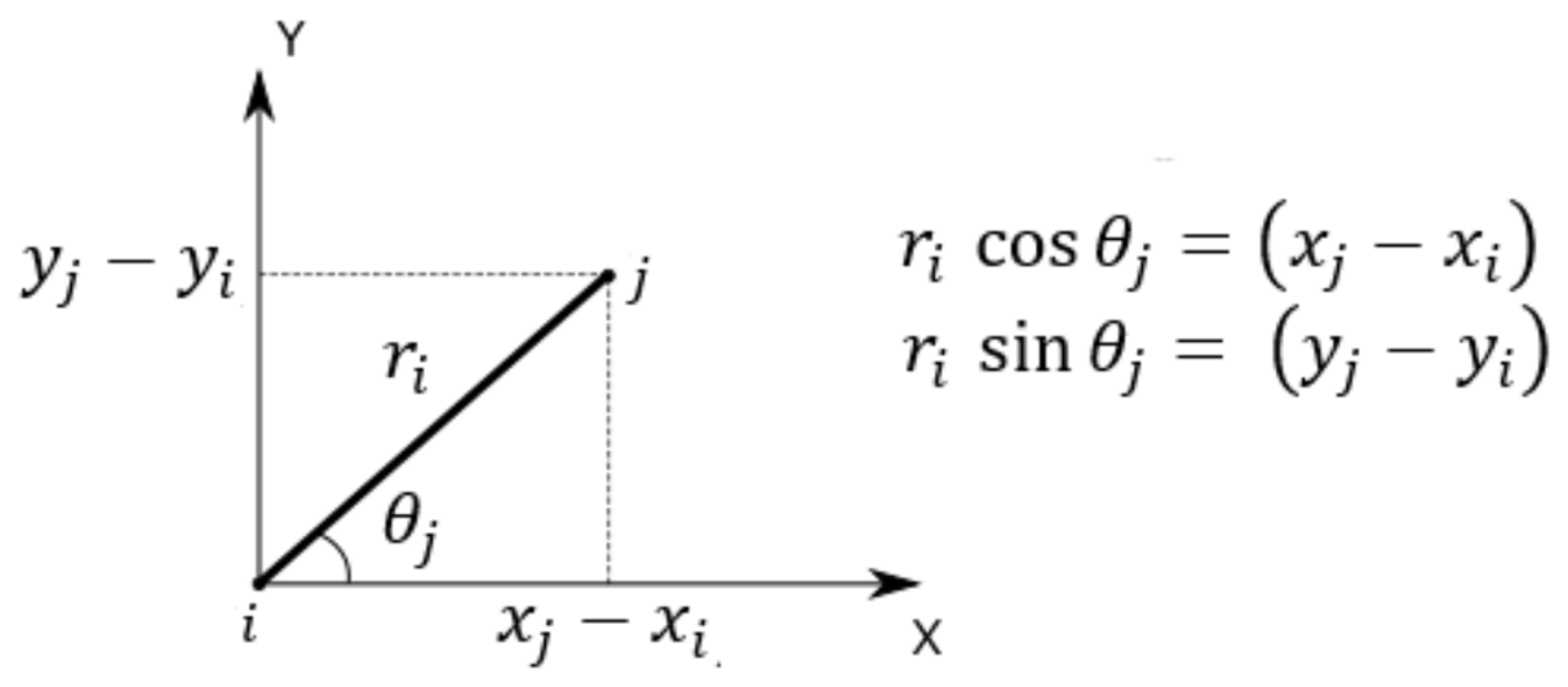
3.1. Kinematic Model
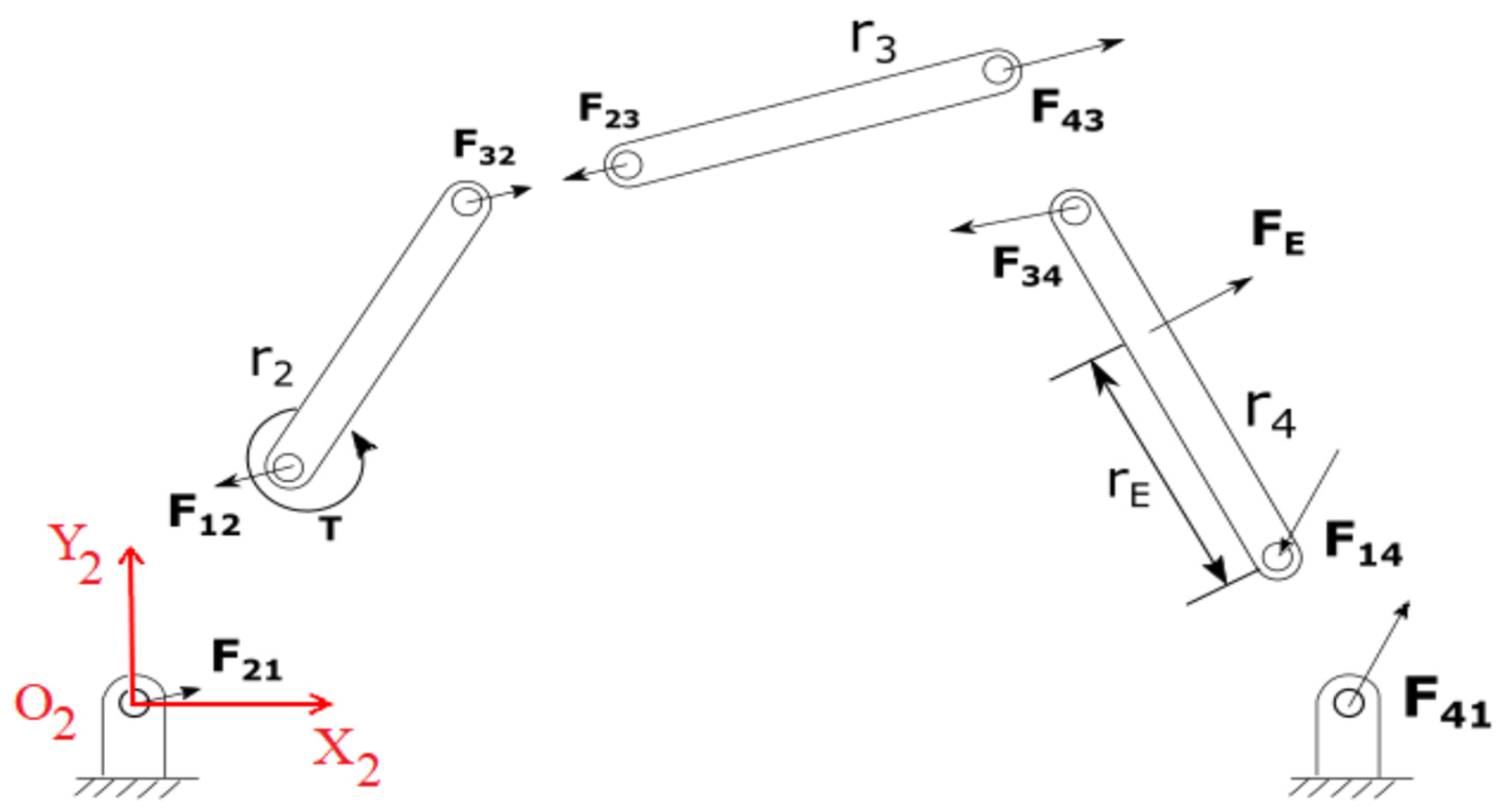
To reproduce the movement of the ankle, it is necessary to use a mechanism that has an oscillatory angular output compatible with its amplitude. In this paper, a planar four-bar mechanism of the continuous input and oscillatory output type (crank–rocker) was used. To properly size the parts that make up the mechanism for ankle rehabilitation, an analytical method was used based on static balance [27] to find the dimensions that make it possible to obtain the desired angular output for the ankle, as well as guarantee that the tensions produced by the ankle reactions are supported by the components. For mathematical modeling, it was considered that the links are ideal, with negligible mass and without friction and/or clearances in the connections between the elements. These considerations were used because the mechanism is operated at low velocity and acceleration due to the nature of the rehabilitation exercises [8]. The link lengths and angles of a crank–rocker model are shown in Figure 2. The angle θ 2 needs to turn complete rotations, and the angle θ 4 needs to have the angular displacement of the ankle joint.
The crank–rocker geometric relations are obtained using the law of cosines, (1) to (5).
s = r 1 2 + r 2 2 2 r 1 r 2 cos θ 2
β = cos 1 [ r 1 2 + s 2 r 2 2 2 r 1 s ]
ψ = cos 1 [ r 3 2 + s 2 r 4 2 2 r 3 s ]
λ = cos 1 [ r 4 2 + s 2 r 3 2 2 r 4 S ]
γ = ± cos 1 [ r 4 2 + r 3 2 s 2 2 r 4 r 3 ]
The output of the system can be obtained by applying (6) to (9) using the relations from (1) to (5) and angles θ3 and θ4.
θ 3 = ψ β , 0 ° θ 2 < 180 °  
θ 3 = ψ + β , 180 ° θ 2 < 360 °
θ 4 = 180 ° λ β , 0 ° θ 2 < 180 °
θ 4 = 180 ° λ + β , 180 ° θ 2 < 360 °

3.2. Static Model

For the static modeling, the inertial reference O2X2Y2 was used, represented in Figure 2, where the sum of the moment was calculated in relation to joints O2, A, and O4 for the equilibrium of links r2, r3, and r4, respectively.
For each force Fj, the term i indicates the index of the link that performs the force, and j is the link that receives the effort as shown in Figure 3.
Through the static equilibrium equations of each element, it is possible to obtain the equilibrium matrix of the system. The equations are obtained by applying Newton’s Second Law to the x and y components, (10) and (11), and from the equilibrium of moments, (12). Thus, there are three equations for each element of the mechanism, resulting in a 9 × 9 equilibrium matrix, which is represented in (13).
  F x = 0
  F y = 0
  M z = 0
Applying the matrix form to (10) to (12), we have: [A] {F} = {B}
1 0 1 0 0 0 0 0 0 0 1 0 1 0 0 0 0 0 0 0 r 2 sin θ 2 r 2 cos θ 2 0 0 0 0 1 0 0 1 0 1 0 0 0 0 0 0 0 1 0 1 0 0 0 0 0 0 0 r 3 sin θ 3 r 3 cos θ 3 0 0 0 0 0 0 0 1 0 1 0 0 0 0 0 0 0 1 0 1 0 0 0 0 0 r 4 sin θ 4 r 4 cos θ 4 0 0 0 · F 12 x F 12 F 32 y F 32 y F 43 x F 43 y F 14 x F 14 y T = 0 0 0 0 0 0 F E x F E y r E sin θ 4 F E x r E cos θ 4 F E x
The components of forces Fj in (13) will be used to determine the efforts and stresses in the links. The relations of this model will also be used to perform an optimized search for the best link lengths using an evolutionary algorithm.
The following sections provide the calculation of the link stress. Equation (14) and bending momentum stress, Equation (15), and Equation (16) are calculated considering the sum of the normal traction/compression.
σ Ni = F xi cos   θ 2 A i + F yi sin   θ 2 A i
σ Bi = F xi cos   θ 2   d i 2   I i + F yi sin   θ 2   d i 2   I i
σ ri = σ Ni + σ Bi
where Ai is the transversal section and Ii is the inertia momentum of the link i, di is the distance of the maximum bending stress point and the neutral line of the link i.

3.3. Singularity Analysis

To ensure the correct functioning of a mechanism, it is necessary to carry out an analysis of mobility and possible unique positions. The methodology used is based on [28], which presents the definition of singularity as the impossibility of solving the kinematic problem mathematically at certain points of a mechanism, which can be physically understood as points that, locally or globally, alter the mobility of a mechanism, leading to a lack of control of one or more joints during their movement cycle.
To determine the possible singularity positions in closed kinematic chain mechanisms, a methodology based on the relations of the geometric matrix of the system and the eigenvalue problem generated from them will be used [28,29,30]. The first step to obtaining the singularity positions is to obtain the geometric matrix of the system, directed to planar mechanisms with rotational joints. Thus, consider a link of length r1 inclined at an angle θj with respect to the X axis, and its ends are called “nodes”, with indices i and j, as shown in Figure 4.
From Figure 4, one can write:
r i = ( x j x i ) cos θ j + ( y j y i ) sin θ j
Rewriting in matrixial form, (17), we have
r i = { x i   y i   x j   y j } ( cos θ j sin θ j cos θ j sin θ j ) = { x e } T { h }
where {xe} is the coordinate vector of link ri with nodes i, j. By squaring (18), there is
r i 2 = { x i y i x j y j }
[ cos 2 θ j cos θ j sin θ j cos 2 θ j cos θ j sin θ j cos θ j sin θ j sin 2 θ j cos θ j sin θ j sin 2 θ j cos 2 θ j cos θ j sin θ j cos 2 θ j cos θ j sin θ j cos θ j sin θ j sin 2 θ j cos θ j sin θ j sin 2 θ j ] { x i y i x j y j }
r i 2 = { x e } T [ G e ] { x e }
The matrix [Ge] is the elementary geometrical matrix of link i and has a null matrixial product with the velocity vector { x e ˙ } expressed using (21).
[ G e ]   { x e ˙ } = { 0 }
Equation (18) is a linear system in the function of i, j node velocities written for all links of the proposed ankle mechanism.
Link r 2 is formed by nodes one and two, link r 3 by nodes two and three, and link r 4 by nodes three and four.
Considering that the imposed restraints in nodes one and four are fixed points with the null velocity, we can obtain the nodal velocities using (22).
[ G ]   { x ˙ } = { 0 } [ 0 0 0 0 0 0 1 0 0 0 0 0 0 0 0 1 c 2 θ 2 + c 2 θ 3 c θ 2 s θ 2 + c θ 3 s θ 3 c 2 θ 3 c θ 3 s θ 3 0 0 0 0 c θ 2 s θ 2 + c θ 3 s θ 3 s 2 θ 2 + s 2 θ 3 c θ 3 s θ 3 s 2 θ 3 0 0 0 0 c 2 θ 3 c θ 3 s θ 3 c 2 θ 3 + c 2 θ 4 c θ 3 s θ 3 + c θ 4 s θ 4 0 0 0 0 c θ 3 s θ 3 s 2 θ 3 c θ 3 s θ 3 + c θ 4 s θ 4 s 2 θ 3 + s 2 θ 4 0 0 0 0 0 0 0 0 1 0 0 0 0 0 0 0 0 1 0 0 ] ( y ˙ 1 x ˙ 2 y ˙ 2 x ˙ 3 y ˙ 3 x ˙ 4 y ˙ 4 )
The [G] matrix, (22), is used to find the singularities in all mechanism workspaces, corresponding to finding the eigenvectors {vi} and the eigenvalues λ, (23).
[ G ]   { x ˙ } = λ { x ˙ }

4. Evolutional Algorithm and Mathematical Results

To obtain the link lengths r 1 , r 2 , r 3 , and r 4 , an evolutionary algorithm was developed, with the link boundary conditions in relations (1) to (5). The developed evolutionary algorithm [31] was set with a population of 50 individuals and link lengths varying from 100 to 300 mm.
The evolutionary algorithm use equality constraints given using (24) to (28):
h 1 = | max ( imag ( γ ) ) |
h 2 = | max ( θ 4 ) min ( θ 4 ) | 80 °
h 3 = | max ( γ ) min ( γ ) | 120 °
h 4 = max | 2   ·   R 32 _ y + 2   ·   R 43 _ y + 2   ·   R 14 _ y |
h 5 = max | 2   ·   R 32 _ x + 2   ·   R 43 _ x + 2   ·   R 14 _ x |
The inequality constraint is given using (29) as
g 1 = min ( γ ) 30 °
The objective function to obtain the links length is obtained using (30) and a pseudo-objective function was used, which works like the traditional objective function, applying penalties when restrictions are violated (31).
FO _ links = | min ( θ 4 ) |
= FO _ links + 1000   ·   ( max ( 1 × 10 10 ,   h 1 ) ) 2 + ( max ( 1 × 10 10 ,   h 2 ) ) 2 + ( max ( 1 × 10 10 ,   h 3 ) ) 2 + ( max ( 1 × 10 10 ,   g 1 ) ) 2
After obtaining the link lengths, the objective function was expanded to consider the link stress. The transversal sections of the links are then selected using a differential evolution algorithm with the objective function given using (32):
FO = max ( [   max | σ r 2 |   max | σ r 3 |   max | σ r 4 |   ] )
A pseudo-objective function, Ft, was used to obtain the transversal sections of the links, which works like the traditional objective function, applying penalties when restrictions are violated (33).
Ft = FO + 1000   · ( max ( 1 × 10 10 ,   h 1 ) ) 2 + ( max ( 1 × 10 10 ,   h 2 ) ) 2 + ( max ( 1 × 10 10 ,   h 3 ) ) 2 + ( max ( 1 × 10 10 ,   h 4 ) ) 2 + ( max ( 1 × 10 10 ,   h 5 ) ) 2 + ( max ( 1 × 10 10 ,   g 1 ) ) 2
The link lengths calculated are r1 = 280 mm, r2 = 104 mm, r3 = 235 mm, and r4 = 164 mm. Generally, the speed and acceleration are considered low in rehabilitation exercises [8], and a static model for calculating the forces on each link and selecting the transversal section is considered in this paper. The ankle device was developed considering a subject with a height of 1.80 m and weight of 150 kg as the external load. A factor of safety of 1.5 was considered as a function of mathematical simplification, such as clearances, friction, and load variations. The simulation considers links made of aluminum alloy with a strength of 276 MPa [32]. The transversal sections used, and the maximum stress values of the proposed mechanism links, are given in Table 1.
To transmit the input movement from the subject’s upper arm to the link r 2 and to decrease the necessary torque to an acceptable level, a chain drive is used (Figure 5). The value of 71 Nm for male healthy subjects was used for the maximum torque of the human arm, and the value of 33 Nm was used for females [33]. After the stroke, it was demonstrated that the torques in the upper and lower limbs are smaller when compared to healthy subjects [34,35]. Figure 5 shows the input torque, T, made over the link r 2 transmitted using the chain drive. The maximum torque in the ankle is 3.82 Nm (Figure 6). A transmission relation of three is used for the patient to have a comfortable crank movement in the function of the possible neurological problems. The center distance of the two sprockets is defined in function of the upper limb workspace [36] to permit the complete crank revolution.
From (23), only the first and seventh eigenvalues change their values along the motion cycle, and the other eigenvalues remain constant. For the mechanism to present singularities, the eigenvalues need to be zero. Figure 7 shows the graphic of the value variation of the eigenvalues, and the proposed mechanism did not reach a zero value inside the workspace; thus, the mechanism is free of singularities.

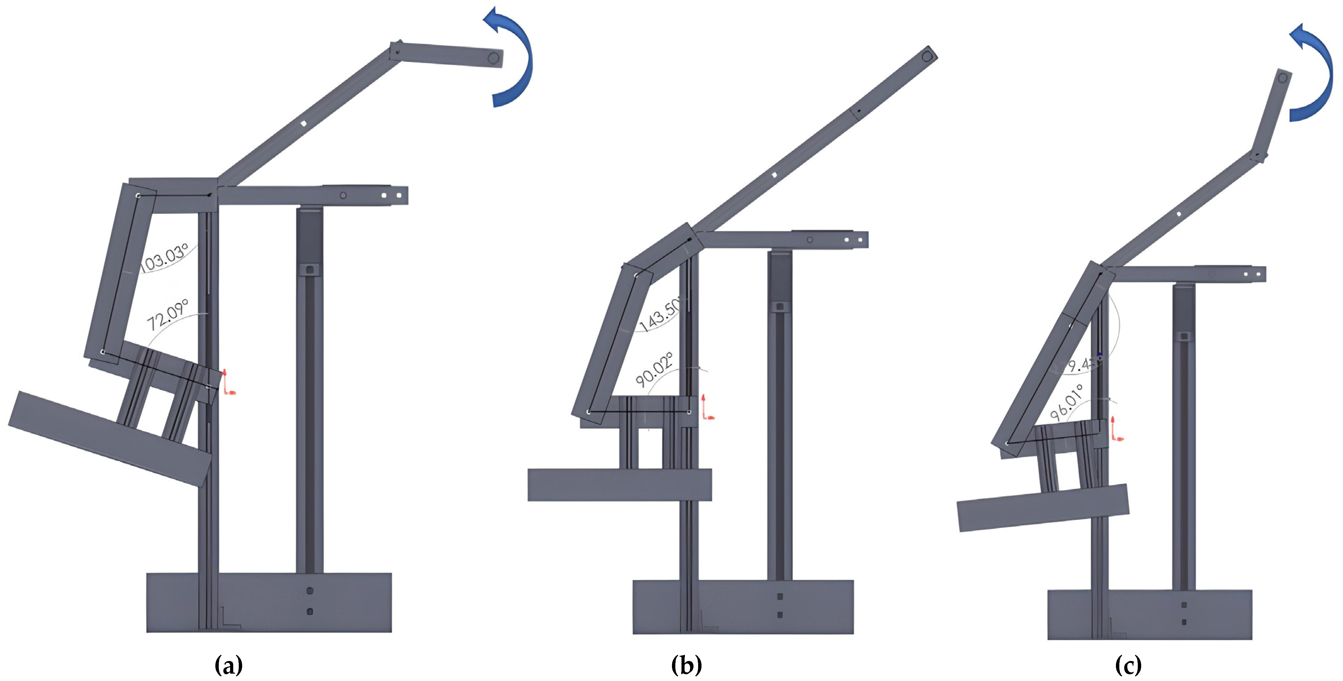
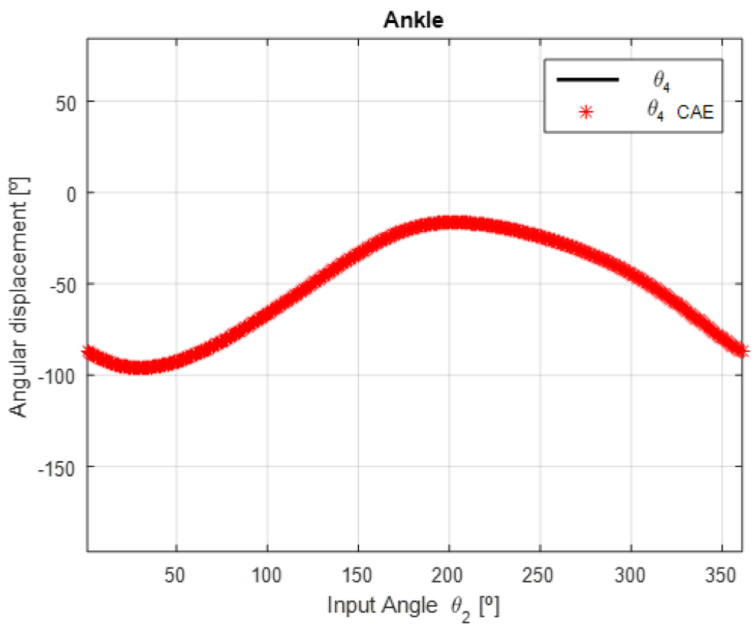
5. CAD/CAE Simulations and Results

Computer-aided design (CAD) and computer-aided engineering (CAE) models of the proposed device were built and submitted to simulations of the complete cycle of motion. Figure 8 shows the CAD/CAE model of the proposed device to simulate the movement of the structure. Figure 9 shows the simulation motion to one complete cycle (0° to 360° of the input link r2 rotation). Figure 9a shows the initial position with input r2 = 0°, Figure 9b represents the foot support parallel to the floor, Figure 9c shows the extension movement, Figure 9d is the return of the foot support parallel to the floor, Figure 9e–g represents the flexion movement, and Figure 9i the return to the initial configuration.
Figure 10 shows the comparison of the output angle θ4 to the mathematical model, (8–9) and CAE simulation. The results are practically the same (Figure 10). The mathematical model has a maximum amplitude of 96.02° and a minimum amplitude of 16.33° with a range of 79.69°. In the CAD/CAE model, the maximum amplitude and the minimum amplitude were the same as those in the mathematical model. From Figure 1, the range of ankle movement used to model the device was 80°, and the evolutionary algorithm gave a result with an error of 0.39%.

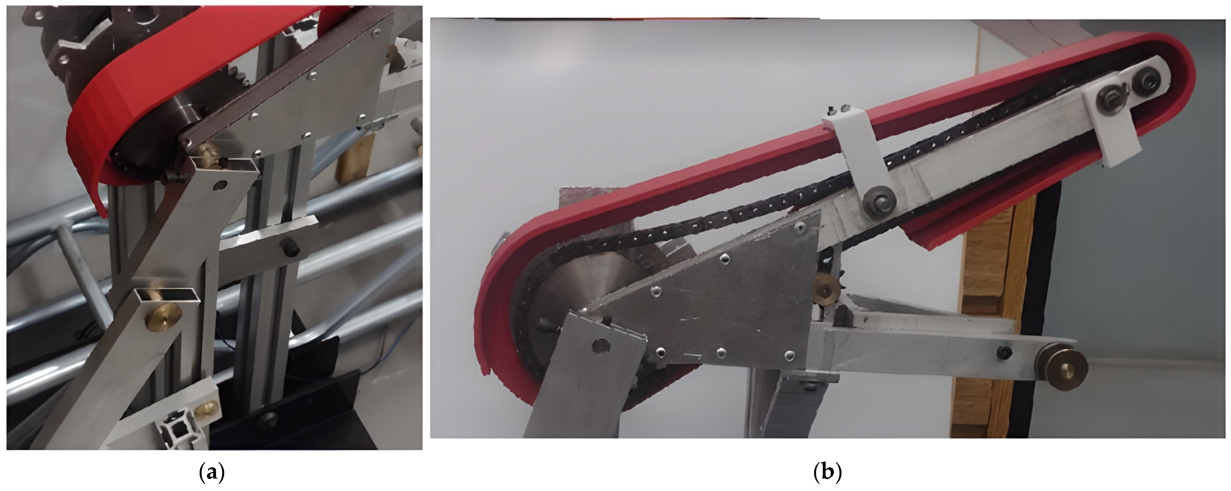
6. Ankle Device Prototype

From the CAD/CAE simulations carried out with the aid of the SolidWorks® software, the prototype was manufactured (Figure 11). To build the mechanism, rectangular aluminum profiles 1/2” × 1” × 2 mm, ASA-40 1/2” chain, 11-tooth toothed pulleys (drive pulley and tensioning pulley) and 33-tooth toothed pulley (drive pulley) were used. The rotation joints were machined in brass (Figure 12a). A fairing covering the chain has been designed for patient protection (Figure 12b).
To test the functioning of the prototype, it was activated manually continuously through the input handle (18 complete turns), while the angular output θ4 was obtained using a goniometer of Miotec, with a precision of ± 0.05° and an acquisition rate of 2000 Hz (Table 2). This test resulted in an amplitude of 84° ± 2.36° (mean ± standard deviation). Compared with the mathematical model, we have an error of 5.41%. This error is probably a function of small differences in dimensions due to the manufacture of parts, assembly, and misalignments.
Figure 13 shows a volunteer using the proposed device. The amplitude of the ankle joint was measured using the Miotec goniometer, and the results were 69.14° ± 0.01° (mean ± std. deviation). The test was made with free movement of the lower limb, and the device moved the ankle with a small rotation of the knee and with passive rotation of the hip; thus, the ankle range movement was smaller. Anatomical studies indicate that joint position changes at the knee and hip influence ankle range of motion [37,38]. In order to carry out the tests with patients, it will be necessary to use an orthosis to immobilize the knee and hip, allowing only the movement of the ankle. Additionally, due to the difference in dimensions and height of the patients, it will be necessary to use a chair with height adjustment, allowing the standardization of the tests.
The experiments were approved by the local ethics committee UFU (protocol CAAE: 01305318.2.0000.5152), and the participant provided written informed consent prior to the experiments.
The prototype permits clockwise or counterclockwise movements in a specific range of motion with oscillatory crank movements. In the case of hemiplegia, the patient has the options of just oscillating the crank or using the healthy upper limb to move the device. This characteristic permits patients with lower mobility to use the device. The video footage of the experimental tests can be accessed at https://drive.google.com/file/d/1CmulvQH66Jt1SgLkKgfHNCgGTiP3DeRU/view?usp=share_link (accessed on 16 February 2023).

7. Conclusions

This paper proposes a nonmotorized and self-operated structure for the rehabilitation of the human ankle based on a four-bar mechanism. The mathematical modeling based on the static balance of the four-bar mechanism, combined with the optimization through a genetic algorithm of the differential evolution type, made it possible to obtain the dimensions of the device with angular output satisfactorily close to the natural amplitudes of the ankle flexion–extension movement. The stress analysis carried out demonstrated that the mechanism is not subjected to high tensions in its links, which allows the choice of light materials, such as aluminum, as well as the use of rectangular tube profiles for the knee mechanisms, which reduces material costs and favors the accessibility/low cost of the structure. Through the construction of the prototype for the movement of the ankle, it was possible to demonstrate the fidelity of the experimental model to what was expected in the mathematical model. The collected data point to the repeatability of the mechanism’s output movement with low error. The tests also showed that the structure can be easily handled by healthy individuals without the need for prior training. As the structure is activated by the user himself from his upper limb, there is the possibility of new rehabilitation protocols to simultaneously stimulate the upper and lower limbs, fundamental in patients with strokes who have movement weaknesses in both limbs. The proposed device was developed and was aimed at the rehabilitation of patients with impaired limb movement or low mobility, including the improvement of motor skills and proprioception of the patient’s ankle joint or neurological injuries such as drop foot following stroke. The device presented in this paper aims to be low-cost due to the absence of actuators and sophisticated control systems, being easy to use by patients and health professionals, and being easy to build for use in future clinics and hospitals for the treatment of ankle problems. It is noteworthy that the study of the best way to fix the patient’s foot in the structure should be carried out while taking into account comfort and safety issues. Future studies to be carried out on this device should seek to improve its fixation base, use of a height-adjustable chair, mobilization of the thigh to allow only movement of the ankle, and experimental tests with patients.

Author Contributions

Conceptualization, R.S.G. and L.A.O.R.; methodology, R.S.G., L.A.O.R. and G.C.; software, L.A.O.R. and R.H.; validation, R.S.G., L.A.O.R., R.H. and G.C.; formal analysis, R.S.G., L.A.O.R., R.H. and G.C.; investigation, R.S.G., L.A.O.R., R.H. and G.C.; resources, R.S.G., L.A.O.R., R.H. and G.C.; data curation, R.S.G., L.A.O.R., R.H. and G.C.; writing—original draft preparation, R.S.G. and G.C.; writing—review and editing, R.S.G. and G.C.; visualization, R.S.G., L.A.O.R., R.H. and G.C.; supervision, R.S.G. and G.C.; funding acquisition, R.S.G. and G.C. All authors have read and agreed to the published version of the manuscript.

Funding

This research was partially funded by the Federal University of Uberlândia, FAPEMIG, CNPq (process 303511/2021-4), and CAPES—Finance Code 001 and by the PNRR MUR project PE0000013-FAIR.

Institutional Review Board Statement

The experiments were approved by the local ethics committee (Protocol CAAE: 01305318.2.0000.5152).

Informed Consent Statement

The participant provided written informed consent prior to the experiments.

Data Availability Statement

There are no additional files. All necessary data have been included in the body of the text.

Conflicts of Interest

The authors declare no conflict of interest.

References

  1. Mattacola, C.G.; Dwyer, M.K. Rehabilitation of the Ankle After Acute Sprain or Chronic Instability. J. Athl. Train. 2002, 37, 413–429. [Google Scholar] [PubMed]
  2. Martin, R.L.; Stewart, G.W.; Conti, S.F. Posttraumatic Ankle Arthritis: An Update on Conservative and Surgical Management. J. Orthop. Sport. Phys. Ther. 2007, 37, 253–259. [Google Scholar] [CrossRef]
  3. Gaddi, D.; Mosca, A.; Piatti, M.; Munegato, D.; Catalano, M.; Di Lorenzo, G.; Turati, M.; Zanchi, N.; Piscitelli, D.; Chui, K.; et al. Acute Ankle Sprain Management: An Umbrella Review of Systematic Reviews. Front. Med. 2022, 9, 868474. [Google Scholar] [CrossRef]
  4. Dong, M.; Zhou, Y.; Li, J.; Rong, X.; Fan, W.; Zhou, X.; Kong, Y. State of the art in parallel ankle rehabilitation robot: A systematic review. J. NeuroEng. Rehabil. 2021, 18, 52. [Google Scholar] [CrossRef] [PubMed]
  5. Gonçalves, R.S.; Rodrigues, L.A.O.; Humbert, R.; Carbone, G. Development of a Nonmotorized Mechanism for Ankle Rehabilitation. Eng. Proc. 2022, 24, 19. [Google Scholar] [CrossRef]
  6. Alves, T.; Gonçalves, R.S.; Carbone, G. Serious Games Strategies with Cable-Driven Robots for Bimanual Rehabilitation: A Randomized Controlled Trial with PostStroke Patients. Front. Robot. AI 2022, 9, 739088. [Google Scholar] [CrossRef]
  7. Gonçalves, R.S.; Soares, G.; Carvalho, J.C. Conceptual design of a rehabilitation device based on cam-follower and crank-rocker mechanisms hand actioned. J. Braz. Soc. Mech. Sci. Eng. 2019, 41, 277. [Google Scholar] [CrossRef]
  8. Gonçalves, R.S.; Krebs, H.I. MIT-Skywalker: Considerations on the Design of a Body Weight Support System. J. Neuroeng. Rehabil. 2017, 14, 88. [Google Scholar] [CrossRef] [Green Version]
  9. Gonçalves, R.S.; Rodrigues, L.A.O. Development of nonmotorized mechanisms for lower limb rehabilitation. Robotica 2021, 40, 102–119. [Google Scholar] [CrossRef]
  10. Gonçalves, R.S.; Carvalho, J.C.M. Robot Modeling for Physical Rehabilitation. In Service Robots and Robotics: Design and Application; IGI Global: Hershey, PA, USA, 2012; pp. 154–175. [Google Scholar] [CrossRef] [Green Version]
  11. Gherman, B.; Birlescu, I.; Plitea, N.; Carbone, G.; Tarnita, D.; Pisla, D. On the singularity-free workspace of a parallel robot for lower-limb rehabilitation. Proceedings of the Romanian Academy Series A–Mathematics Physics Technical Sciences. Inf. Sci. 2019, 20, 383–391. [Google Scholar]
  12. Alves, T.; Gonçalves, R.S.; Carbone, G. Serious Games Strategies with Cable-Driven Robots for Rehabilitation Tasks. In New Trends in Medical and Service Robotics; Rauter, G., Carbone, G., Cattin, P.C., Zam, A., Pisla, D., Riener, R., Eds.; Springer: New York, NY, USA, 2022; Volume 106. [Google Scholar] [CrossRef]
  13. Pisla, D.; Nadas, I.; Tucan, P.; Albert, S.; Carbone, G.; Antal, T.; Banica, A.; Gherman, B. Development of a Control System and Functional Validation of a Parallel Robot for Lower Limb Rehabilitation. Actuators 2021, 10, 277. [Google Scholar] [CrossRef]
  14. Tucan, P.; Ulinici, I.; Pop, N.; Puskas, F.; Carbone, G.; Gherman, B.; Luchian, I.; Pisla, D. Ankle Rehabilitation of Stroke Survivors Using Kuka LBR Iiwa. In New Trends in Medical and Service Robotics; Rauter, G., Cattin, P.C., Zam, A., Riener, R., Carbone, G., Pisla, D., Eds.; Springer: New York, NY, USA, 2021; Volume 93. [Google Scholar] [CrossRef]
  15. Gonçalves, R.S.; Brito, L.S.F.; Moraes, L.P.; Carbone, G.; Ceccarelli, M. A fairly simple mechatronic device for training human wrist motion. Int. J. Adv. Robot. Syst. 2020, 17, 1729881420974286. [Google Scholar] [CrossRef]
  16. Carbone, G.; Gonçalves, R.S. Editorial: Robot-assisted rehabilitation for neurological disorders. Front. Robot. AI 2022, 9, 1014681. [Google Scholar] [CrossRef] [PubMed]
  17. Pinto, D.; Garnier, M.; Barbas, J.; Chang, S.H.; Charlifue, S.; Field-Fote, E.; Furbish, C.; Tefertiller, C.; Mummidisetty, C.K.; Taylor, H.; et al. Budget impact analysis of robotic exoskeleton use for locomotor training following spinal cord injury in four SCI Model Systems. J. Neuro. Eng. Rehabil. 2020, 17, 4. [Google Scholar] [CrossRef] [Green Version]
  18. Li, L.; Tyson, S.; Weightman, A. Professionals’ Views and Experiences of Using Rehabilitation Robotics with Stroke Survivors: A Mixed Methods Survey. Front. Med. Technol. 2021, 3, 780090. [Google Scholar] [CrossRef] [PubMed]
  19. Wang, X.; Qiu, J.; Fong, D.T. The applications of wearable devices in the rehabilitation of ankle injuries: A systematic review and meta-analysis. Med. Nov. Technol. Devices 2023, 17, 100210. [Google Scholar] [CrossRef]
  20. Zhetenbayev, N.; Zhauyt, A.; Balbayev, G.; Shingissov, B. Robot device for ankle joint rehabilitation: A review. Vibroengineering PROCEDIA 2022, 41, 96–102. [Google Scholar] [CrossRef]
  21. Wang, T.; Zhang, B.; Liu, C.; Liu, T.; Han, Y.; Wang, S.; Ferreira, J.P.; Dong, W.; Zhang, X. A Review on the Rehabilitation Exoskeletons for the Lower Limbs of the Elderly and the Disabled. Electronics 2022, 11, 388. [Google Scholar] [CrossRef]
  22. Shi, B.; Chen, X.; Yue, Z.; Yin, S.; Weng, Q.; Zhang, X.; Wang, J.; Wen, W. Wearable Ankle Robots in Post-stroke Rehabilitation of Gait: A Systematic Review. Front. Neurorobot. 2019, 13, 63. [Google Scholar] [CrossRef] [Green Version]
  23. Huang, H.J.; Ferris, D. Neural coupling between upper and lower limbs during recumbent stepping. J. Appl. Physiol. 2004, 97, 1299–1308. [Google Scholar] [CrossRef]
  24. Klarner, T.; Barss, T.S.; Sun, Y.; Kaupp, C.; Loadman, P.M.; Zehr, E.P. Exploiting Interlimb Arm and Leg Connections for Walking Rehabilitation: A Training Intervention in Stroke. Neural Plast. 2016, 2016, 1–19. [Google Scholar] [CrossRef] [PubMed] [Green Version]
  25. Kapandji, I. Physiology of the Joints: Lower Limb, 6th ed.; Churchill Livingstone: London, UK, 2010. [Google Scholar]
  26. Brockett, C.L.; Chapman, G.J. Biomechanics of the ankle. Orthop. Trauma 2016, 30, 232–238. [Google Scholar] [CrossRef] [PubMed] [Green Version]
  27. Uicker, J.J.; Pennock, G.R.; Shigley, J.E.; McCarthy, J.M. Theory of machines and mechanisms. J. Mech. Des. 2003, 125, 650. [Google Scholar] [CrossRef] [Green Version]
  28. Altuzarra, O.; Pinto, C.; Avilés, R.; Hernández, A. A practical procedure to analyze singular configurations in closed kinematic chains. IEEE Trans. Robot. 2004, 20, 929–940. [Google Scholar] [CrossRef]
  29. Altuzarra, O.; Salgado, O.; Petuya, V.; Hernández, A. Point-based Jacobian formulation for computational kinematics of manipulators. Mech. Mach. Theory 2006, 41, 1407–1423. [Google Scholar] [CrossRef]
  30. Vaida, C.; Birlescu, I.; Pisla, A.; Ulinici, I.; Tarnita, D.; Carbone, G.; Pisla, D. Systematic design of a parallel robotic system for lower limb rehabilitation. IEEE Access 2020, 8, 34522–34537. [Google Scholar] [CrossRef]
  31. Gonçalves, R.S.; Carvalho, J.C.M.; Lobato, F.S. Design of a robotic device actuated by cables for human lower limb rehabilitation using self-adaptive differential evolution and robust optimization. Biosci. J. 2016, 32, 1689–1702. [Google Scholar] [CrossRef]
  32. Davis, J.R. Properties and Selection: Nonferrous Alloys and Special-Purpose Materials. In ASM Handbook; ASM International: Almere, The Netherlands, 2007; Volume 2. [Google Scholar] [CrossRef]
  33. Neumann, D. Kinesiology of The Musculoskeletal System; Elsevier: Amsterdam, The Netherlands, 2010. [Google Scholar]
  34. Freire, B.; Dias, C.P.; Oliveira, L.S.; Goulart, N.B.A.; Lemos, F.A.; Becker, J.; Gomes, I.; Vaz, M.A. Rate of force development and torque production assessment in spastic stroke survivors. Rev. Bras. Cineantropom. Desempenho Hum. 2015, 17, 328–336. [Google Scholar] [CrossRef] [Green Version]
  35. McCrea, P.H.; Eng, J.J.; Hodgson, A.J. Time and magnitude of torque generation is impaired in both arms following stroke. Muscle Nerve 2003, 28, 46–53. [Google Scholar] [CrossRef]
  36. Cho, K.H.; Jeon, Y.; Lee, H. Range of Motion of the Ankle According to Pushing Force, Gender and Knee Position. Ann Rehabil. Med. 2016, 40, 271–278. [Google Scholar] [CrossRef] [Green Version]
  37. Andrade, R.J.; Lacourpaille, S.R.; Freitas, S.R.; McNair, P.J.; Nordez, A. Effects of hip and head position on ankle range of motion, ankle passive torque, and passive gastrocnemius tension. Scand. J. Med. Sci. Sport. 2016, 26, 41–47. [Google Scholar] [CrossRef] [PubMed]
  38. Laribi, M.A.; Carbone, G.; Zeghloul, S. On the Optimal Design of Cable Driven Parallel Robot with a Prescribed Workspace for Upper Limb Rehabilitation Tasks. J. Bionic. Eng. 2019, 16, 503–513. [Google Scholar] [CrossRef]
Figure 1. Ankle movements. (a) Abduction/adduction; (b) dorsiflexion/plantarflexion; (c) eversion/inversion.
Robotics 12 00032 g001
Figure 2. Crank–rocker mechanism variables for the links and angles used in the mathematical model.
Robotics 12 00032 g002
Figure 3. Free body diagram of the links.
Robotics 12 00032 g003
Figure 4. Geometric relations of an elementary link of length ri.
Robotics 12 00032 g004
Figure 5. The mechanism’s design scheme, with an adjustment rail on bar r 4 , the subject’s leg weight load F E , and a chain drive transmitting the torque T from the subject’s hand on bar a 2 to input bar r 2 .
Robotics 12 00032 g005
Figure 6. Input torque calculated for the proposed device.
Robotics 12 00032 g006
Figure 7. Eigenvalues non-zero results for the ankle proposed device.
Robotics 12 00032 g007
Figure 8. CAD/CAE Model of the proposed ankle device.
Robotics 12 00032 g008
Figure 9. The motion simulation sequence of images of the ankle device. (a) initial position with input r2 = 0°; (b) foot support parallel to the floor; (c) extension movement; (d) return of the foot support parallel to the floor; (eh) flexion movement; (i) return to the initial configuration.
Robotics 12 00032 g009aRobotics 12 00032 g009b
Figure 10. Comparison of the output angle θ4 to the mathematical model and CAE simulation.
Robotics 12 00032 g010
Figure 11. Prototype of the proposed ankle device.
Robotics 12 00032 g011
Figure 12. Prototype details. (a) Brass rotational joint; (b) fairing covering chain.
Robotics 12 00032 g012
Figure 13. Experimental test with the ankle device prototype.
Robotics 12 00032 g013
Table 1. Maximum stress calculated for the proposed device.
Stress   r 1   ( MPa ) Stress   r 2   ( MPa ) Stress   r 3   ( MPa ) Stress   r 4   ( MPa ) Transversal Section
(Width/Height/Thickness)
0.420.450.499.521/2″ × 1″ × 2 mm
Table 2. Experimental results of the angular output θ4.
MeasureMax. Flexion [°]Max. Extension [°]Difference [°]
1173.4986.9686.53
2171.1187.4483.67
3173.9788.3985.58
4172.5487.2085.34
5174.6886.9687.72
6172.5486.9685.58
7173.9788.1585.82
8173.7387.2086.53
9173.7387.4386.30
10171.8287.6784.15
11173.7389.5884.15
12168.7288.1580.57
13171.5889.5882.00
14172.0690.0582.01
15169.9288.3981.53
16173.7389.8283.91
17169.9289.3480.58
18169.6889.5880.10
Mean = 84.00° std = 2.36°
Disclaimer/Publisher’s Note: The statements, opinions and data contained in all publications are solely those of the individual author(s) and contributor(s) and not of MDPI and/or the editor(s). MDPI and/or the editor(s) disclaim responsibility for any injury to people or property resulting from any ideas, methods, instructions or products referred to in the content.

