Article

Modeling of a Non-Rigid Passive Exoskeleton-Mathematical Description and Musculoskeletal Simulations

Department of Material and Production, Aalborg University, 9220 Aalborg, Denmark
*
Author to whom correspondence should be addressed.
Robotics 2022, 11(6), 147; https://doi.org/10.3390/robotics11060147
Submission received: 27 October 2022 / Revised: 18 November 2022 / Accepted: 30 November 2022 / Published: 7 December 2022
(This article belongs to the Section Medical Robotics and Service Robotics)

Abstract

:
There is a growing application of passive exoskeletons in the industrial sector with the purpose to reduce the incidence of work-related musculoskeletal disorders (MSDs). Nowadays, while many passive shoulder exoskeletons have been developed to support overhead tasks, they present limitations in supporting tasks such as load lifting and carrying. Further developments are therefore needed to have a wider application of these devices in the industrial sector. This paper presents a modelling procedure of a passive non-rigid exoskeleton for shoulder support that can be used to evaluate the device in its development phase. The modelling began with the definition of the equations to describe the exoskeleton kinematics and dynamics to obtain the support force profile provided by the device over the shoulder flexion angle. A musculoskeletal simulation software was then used to evaluate the effect of the device on the human body. The computed support force profile is in agreement with the purpose of the device, with the maximal support force obtained for a shoulder flexion angle of 85–90°. The maximum support force value had the same magnitude as the one reported by the device user manual (3.5 kg). In particular, for a determined exoskeleton configuration, the maximum support force value computed was 34.3 N, equal to the reported by the manufacturer. The subsequent musculoskeletal simulation showed the ability of the device to reduce the muscular activation of agonist muscles such as the anterior deltoid (−36.01%) compared to the case when the exoskeleton is not used. The musculoskeletal results showed a positive effect of the device on the joint reaction forces at the glenohumeral joint with a reduction up to 41.91%. Overall the methodology and the mathematical model proposed can be used to further develop these devices, making them suitable for a wider range of tasks.

1. Introduction

Exoskeletons as a growing technology are being applied to motor rehabilitation [1,2], military applications [3] and to improve performance and safety in the work environment [4]. These devices work parallel with the human body to support or enhance its capabilities [5]. Exoskeletons can use different types of actuation, being classified as passive exoskeletons if they only use energy-storing systems such as springs and dampers, or active exoskeletons if they use powered motors (e.g., electrical motors) [6]. Exoskeletons can be designed to support the whole human body or just a part of it, such as the back, the upper or lower limbs.
This paper will focus on a passive upper limb exoskeleton designed to support the shoulders of factory workers. Passive exoskeletons are the most commonly applied in working environments thanks to their lower price, weight, simplicity of use and higher reliability compared to active devices [7]. Examples of passive exoskeletons include Skelex [8], Mate [9] and AAU passive shoulder exoskeleton [10].
Exoskeletons are applied in work environments to reduce the risk of work-related musculoskeletal disorders (wMSD) [11]. They act on factors that lead to MSD, particularly muscle activation. By reducing human muscle activity, exoskeleton can delay the insurgence of muscle fatigue, one of the main factors that lead to MSD [12]. Different studies evaluated exoskeletons during commonly performed work tasks such as overhead drilling or wiring and plastering, finding a reduction in muscle activity for the most involved muscles: Deltoids, Teres Major and Biceps Brachii [13,14,15,16]. In addition to muscle activity, studies on the effectiveness of exoskeletons to assist during labour tasks have focused on ratings of perceived exertion and metabolic cost [15,16,17]. Such studies demonstrated that using these devices can be obtained a reduction in the exertion perceived locally and globally while performing the tasks [15,17] and also a reduction of parameters related to the metabolic cost of the task, such as heart rate and oxygen consumption [16,17].
One of the limitations of the passive exoskeletons currently available on the market is the small variety of positions they can effectively support. Currently, these devices are developed to support overhead work. Their application in more complex tasks, that require working under the shoulders level, can present problems as the workers have to contrast the exoskeleton force [18]. Further developments are therefore required to allow a wider application of these devices in the industrial sector.
Musculoskeletal simulation software can be used to improve the design process of exoskeletons. These software would allow a better understanding of the influences of the passive exoskeletons on the human body and test solutions to better support different movements and tasks. Previous studies used musculoskeletal simulation software such as AnyBody Modeling System (AMS) (AnyBody Technology A/S, Aalborg, Denmark) to evaluate different parameters of the human-exoskeletons interaction. Studies on the exoskeletons’ influences on the trunk flexion angle [19] or on the supported body weight percentage by lower limb exoskeleton [20] were performed as long as the modelling validation of an active lower limb exoskeleton looking at the simulated ground reaction forces and centre of pressure position [21]. Both passive and active upper limb devices were also simulated. Changes in muscle activation and joint forces during overhead drilling tasks were studied during the use of a passive device [22]. In [23] a validation of an active exoskeleton device was performed with musculoskeletal simulations before its production. Reference [24] presents a development process of an active exoskeleton device where musculoskeletal simulations are used to find the optimal support torque and application point of exoskeleton support force on the human arm.
Other modelling approaches were adopted to evaluate the human-exoskeleton interaction. In [25] a bond graph model was developed to study the dynamic of the human-exoskeleton system. In [26] a dynamic model was developed to study the coupling between the human body and a lower limb exoskeleton. The human-exoskeleton interaction was also studied in [27] with a dynamic model for an upper limb device. In [27] the hybrid exoskeleton used was based on the same passive device used for our study, but an oversimplified model was used.
The studies presented were relative to exoskeletons with a rigid structure. In this paper, the device presents two non-rigid parts that have the critical purpose of supporting force generation. This type of exoskeleton has the advantage of a better adaptation to the human body shape. They may also be more compact and lighter due to fewer elements than exoskeletons with a rigid structure. The research presented in this paper proposes a methodology that can be used for the development or testing of non-rigid exoskeletons. The first step of the paper is the definition of the equations that describe the kinematic and dynamic behaviour of a commercially available non-rigid upper limb exoskeleton (Skelex 360, Rotterdam, The Netherlands) to compute the support force profile that it provides. Subsequently, the exoskeleton model will be imported into AnyBody to evaluate its effect on human muscle activation.

2. Material and Method

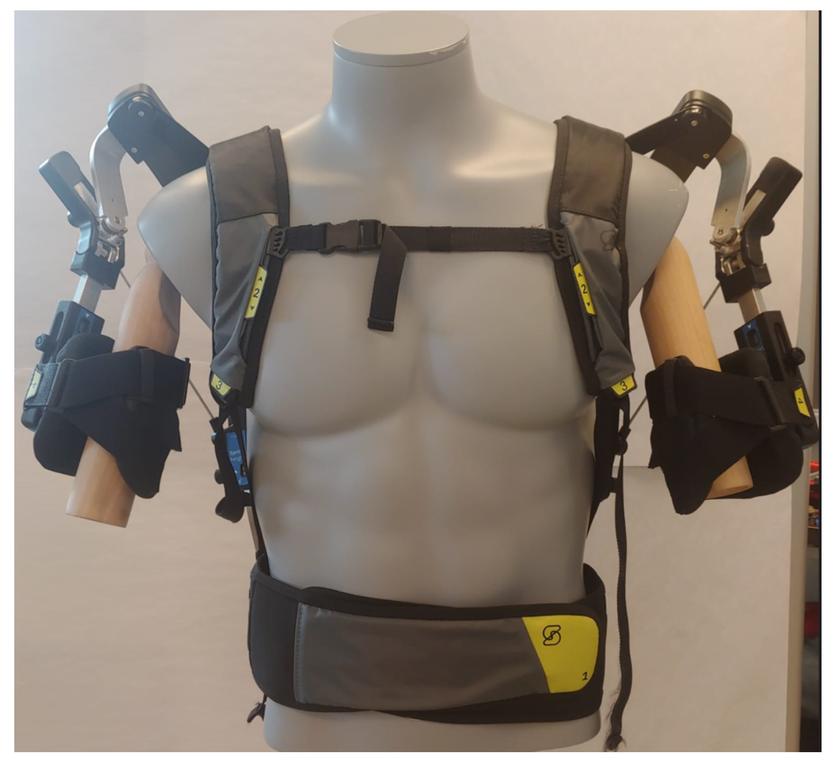
2.1. Passive Exoskeleton

In this paper, we created a 2D mathematical model of a commercially available passive exoskeleton for shoulder support (Skelex 360, Skelex, Rotterdam, The Netherlands, Figure 1). The main characteristic of this device is the non-rigid back structure used to generate the support force. In particular, the exoskeleton presents two elastic elements (stacked carbon fibre leaf springs) [8], one per side, that act like springs. The elastic elements form with the relative cable and shoulder element a closed chain. The cable is hinged on the shoulder element and at the bottom part of the relative elastic element. This closed-chain configuration translates the elastic force of the elastic elements in the support force. The exoskeleton can provide assistance from 0.5 to 3.5 kg [28]. The level of support provided by the device can be changed by increasing or decreasing the distance between the cable connection point on the shoulder element and the centre of rotation of the latter. In total, there are four possible levels representing a minimum distance of 20 mm and a maximum of 50 mm.

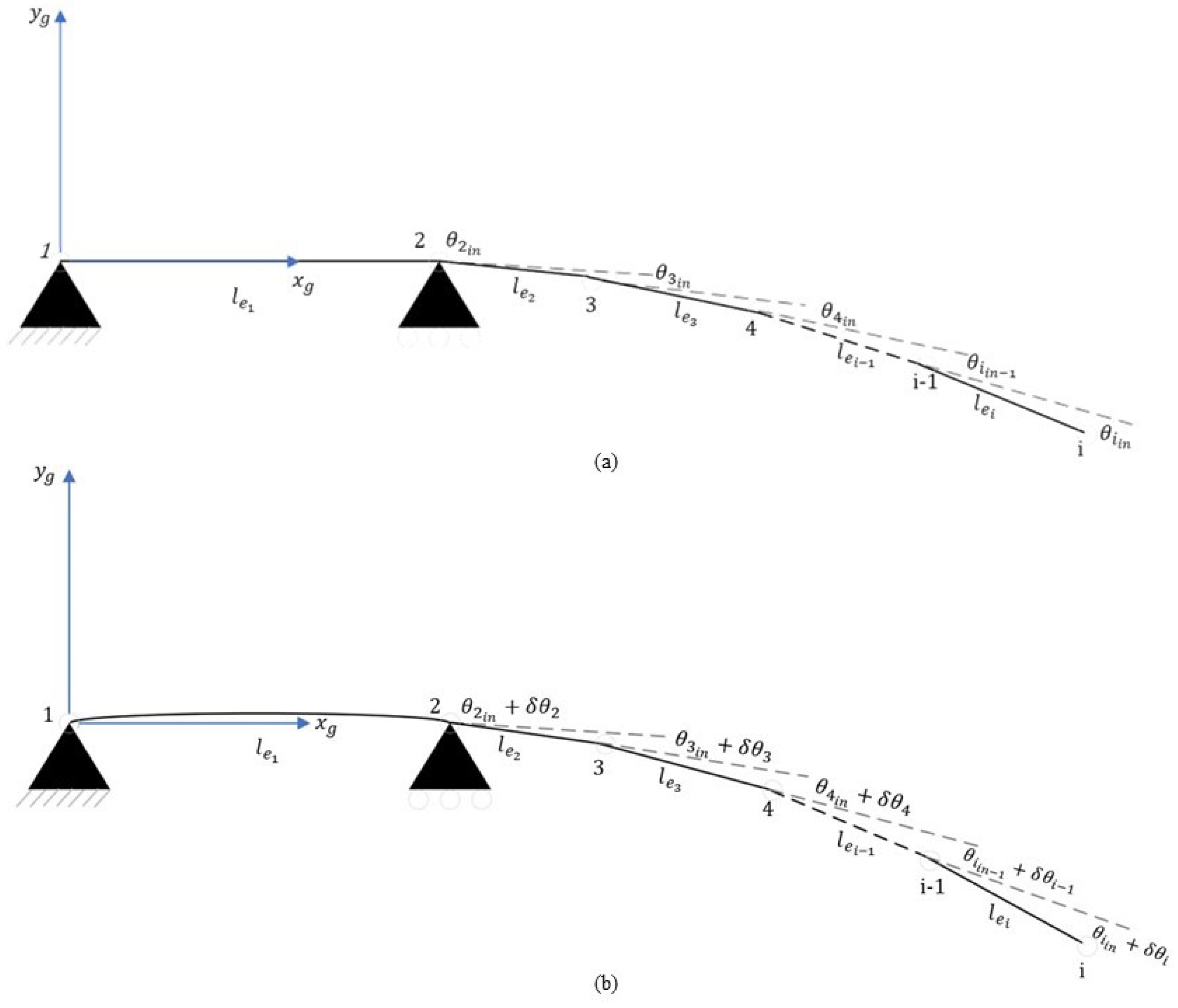
2.2. Exoskeleton Mathematical Model

In order to compute the exoskeleton support force-shoulder angle relation, we first created a 2D mathematical model with MATLAB R2021b (The MathWorks, Inc., Natick, MA, USA). The support forces are generated by the left and right exoskeleton’s flexible back frames. Therefore, the first step was to model these two elastic elements as overhanging beams to compute the exoskeleton bending. However, there were two relevant limitations to account for: the non-linear axes of the beams and the large beam deflection during assistance. Such limitations do not allow the direct application of the Euler–Bernoulli beam theory. To overcome the issues related to the beam structures, we used the co-rotational (CR) beam element formulation proposed in [29] to compute the bending of the elements.
Reference [29] proposed a different formulation of the CR method, of which a review can be found in [30]. Briefly, the beam was discretized into a number of shorter elements that undergo a relative deflection smaller than the beam one, allowing the application of the standard Euler–Bernoulli theory to estimate the deformation of these shorter elements. The first main change of the approach used in [29] consists of defining the element’s rigid CR axis as tangent to the centroid curve of its first node instead of being used as connecting lines of the end node. The second formulation change describes the coordinates of the nodal element in their local reference system and not in a fixed global reference frame [29]. Our case presents some differences from the one proposed in [29]: the back frames have a curved axis and an overhanging beam configuration, not a simple cantilever configuration.
Figure 2 illustrates the theoretical modelling.
We first divided the beam into ten elements where the first element was designed as a simply supported beam; for simplicity with a straight axis. The remaining nine elements were modelled as cantilever beams. We used straight elements also for the overhanging part. The initial curvature was imported by adding an initial angle between the elements ( θ i i n ), Figure 2. These angles were obtained by calculating the derivative at a point of the curvature equation whose polynomial coefficients were obtained with the MATLAB polyval function. While dividing the exoskeleton back springs into elements, the presence of the screws that connect the real springs to the rest of the device was considered. The screws and washers’ presence limits the bending and deformation of the first 28 mm and last 29 mm of the exoskeleton back frames. Therefore, when we created the model, the simply supported beam element length did not include the first part constrained by the screws. The overhanging part was also affected, with the last element, the 9th, 3 mm shorter than the others. Below are reported the general equations of [29] modified to include the initial angle between the beam elements. The force vector f i acting on the i th node can be written as:
f i = R ( θ i i n ) k = 3 i 1 R k 1 k ( δ θ i + θ i i n ) R ( δ θ 2 + θ 2 i n ) f e x t , i 2
Here f e x t is the external force vector: forces acting on the top of the beam elements. R θ i i n and R ( δ θ i + θ i i n ) are respectively the planar rotation matrices of the initial angle ( θ i i n ) and of the deformed shape angle ( δ θ i + θ i i n ) . The rotation angle of the deformed shape in the second point is obtained with the standard load case formula:
δ θ 2 = M 2 · l e 1 3 E I
The deflection angle depends on the length of the first element ( l e 1 ), the Young’s modulus (E), the second moment of inertia of the cross-section area (I) and torque acting on the second node ( M 2 ). M 2 can be obtained by the vector product between the position ( r 3 ) and the force ( f 3 ) vector of the 3rd node expressed in the second frame plus torque acting on the 3rd node m 3 z . The position vector of the endpoint r e n d of the top of the beam, can be formulated as:
r e n d = l e 1 + 28 0 + R T δ θ 2 + θ 2 i n · ( j = 4 i R T ( θ j ) k = 3 i 1 R T k 1 k ( δ θ i + θ i i n ) { r j } + + R T ( θ 3 ) { r 3 } )
To relate spring force to the support force provided, the equations presented in [8] were adapted to our device and used. These equations relate to the relative force generated from the back frame bending F s , the one generated by the connection cable on the shoulder element F c and the resulting support at the human arm F a . To use them with our version of the SkelEx device, we modified them to consider the different shoulder element shapes. In [8], the link has an L-shape; in the case presented here, it has a V-shape with an angle of 140° between the two arms. The two equations are presented below:
F c = F a · B a B c · cos φ 1 α
F s = cos ( α 40 ) sin ( α 40 ) sin ( α 40 ) cos ( α 40 ) · 0 F a + F c cos ( φ 1 ) F c sin ( φ 1 )
with B a and B c being respectively the support force and the cable force arms with respect to the centre of rotation of the shoulder. α is the angle between the line connecting the centre of rotation of the shoulder and the connection point of the cable and the vertical axis. φ 1 is the angle between the cable and the horizontal axis. Equation (4) relates the cable force to the support force. Equation (5) is the relation between the force generated by the spring element and the other two forces. The last step was to combine these two groups of equations with the shoulder position to find the relation between support force and shoulder angle. To do so, a few other equations that express the geometrical relations were added. Figure 3 shows the exoskeleton scheme used to identify these relations.
Equation (6) expresses the position vector ( R c ) of the shoulder rotation centre ( O r ) in the global reference frame; the position vector of the top of the beam was rotated on the first quadrant for simplicity.
R c = x R c y R c = cos π sin π sin π cos π r e n d + R θ P O r t b
Here P O r t b is the position of the shoulder rotation centre expressed in the coordinate system relative to the top of the beam. The distance between the shoulder rotation centre and the cable attachment point at the bottom of the spring was then computed as Equation (7), with x C p b and y C p b being the coordinates of the cable connection point on the exoskeleton back expressed in the global reference system ( O g ).
D c c = x R c x C p b 2 + y R c y C p b 2
Then the angle between the cable and its force arm on the shoulder element was obtained with the law of cosines:
a 1 = cos 1 L c 2 + B c 2 D c c 2 2 · L c · B c
The same law was used in Equation (9) to compute the other internal angle φ 3 of the triangle formed by the above lines and D c c .
φ 3 = cos 1 D c c 2 + L c 2 B c 2 2 · L c · D c c
In Equation (10) the angle between the x-axis and D c c is computed:
φ 2 = tan 1 y R c y C p b x R c x C p b
The angle between the cable arm on the shoulder and the vertical axis, α , is found by
α = 90 + a 1 + φ 2 + φ 3
The system of equations created was then solved with the MATLAB numeric solver by giving the value of α , for which the support force provided was calculated. Before running the simulations, the elastic modulus of the back frames was evaluated. The exoskeleton momentarily disconnected and a three-point bending test was performed using the electro-mechanical testing machine for static testing (Zwick 100 KN, ZwickRoell GmbH & Co. KG, Ulm, Germany).

2.3. Computed Exoskeleton Shape Evaluation

The exoskeleton computed deformed shape was compared with the original shape recorded with a motion capture system (VCAM, Vicon Motion Systems Ltd., Oxford, UK). To record the device shape and its change with the exoskeleton shoulder angle, 15 markers were put along the central axis of the exoskeleton back beam and on reference points on the shoulder-arm mechanism Figure 4. For evaluation, the difference between the deflection calculated from the simulated data and that obtained from the recorded data was computed ( Δ D) and then expressed as a percentage of the length of the beam (400 mm), Equation (12). The deflection of the beam for a given shoulder angle was calculated as the distance between the top beam position for the specific angular value and the top beam position for the most undeformed configuration of the exoskeleton, i.e., when the shoulder flexion angle was 190° for B c = 20 mm and 200° for B c = 50 mm.
Δ D % = ( Simulated deflection Recorded deflection ) / Beam length · 100
The evaluation was performed for the maximum and minimum levels of support, corresponding to a B c value of 50 and 20 mm respectively. For comparison, the recorded deformed exoskeleton shape over different shoulder angles was also computed from the camera recordings with Biomechanical ToolKit (BTK) (v. 0.3dev.0) for MATLAB. The results of the evaluation are presented in Section 3.2.

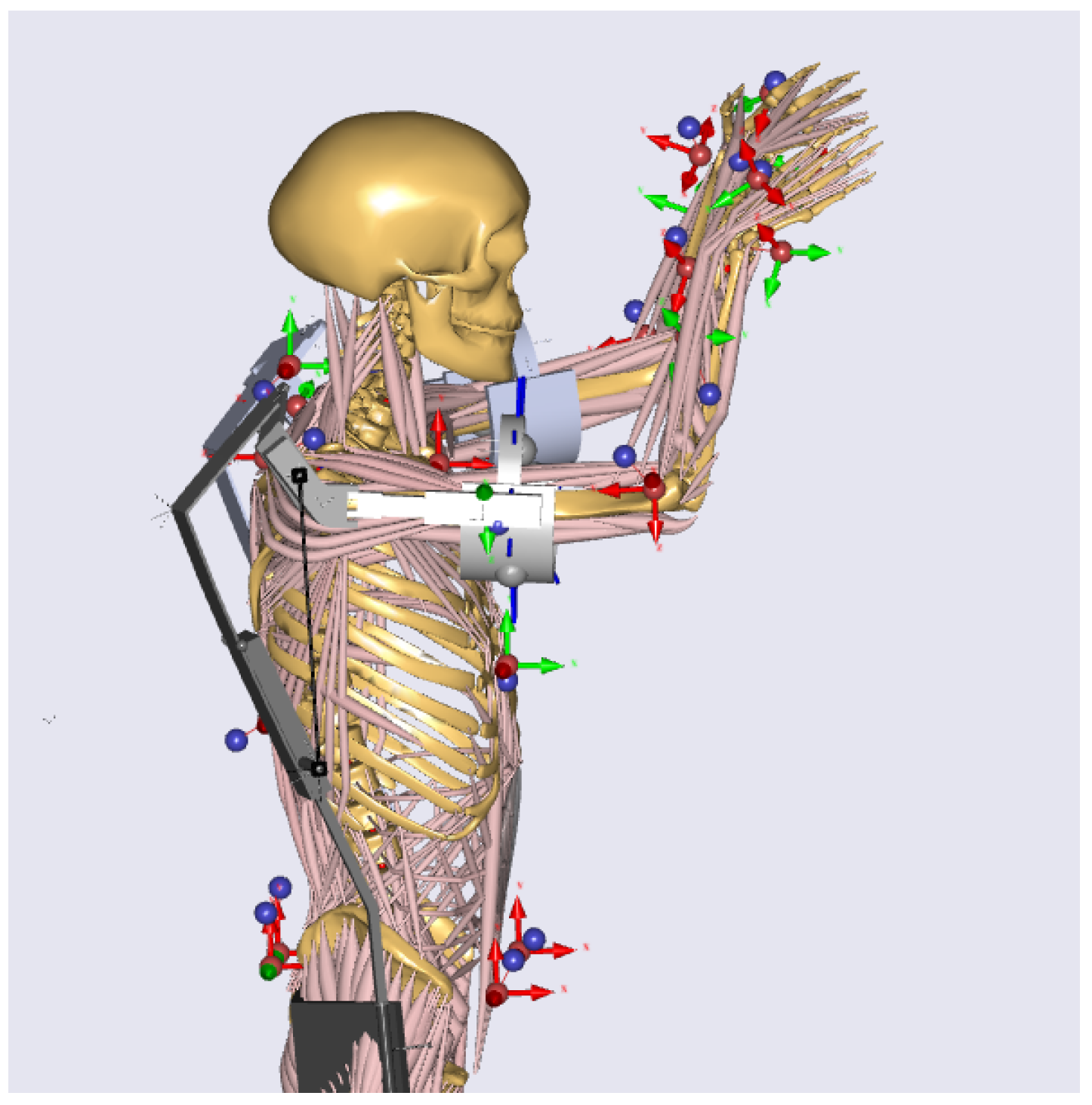
2.4. Musculoskeletal Modelling

The modelling of human performance using the exoskeleton was conducted using dedicated software (Anybody 7,4. AnyBody Technology A/S, Aalborg, Denmark). Firstly, a CAD model of the Skelex device was created with SolidWorks® 2020 (Dassault Systèmes SOLIDWORKS Corporation, Waltham, MA, USA) and then translated into an AnyBody compatible script file using the AnyExp4SOLIDWORKS® plugin (version 1.1.0, AnyBody Technology A/S, Aalborg, Denmark). The human model used in these simulations was the FullBody GRFPrediction one, present in the AnyBody Managed Model Repository (AMMR.v2.4.1). Subsequently, the exoskeleton was connected to the human body model at three points corresponding to the exoskeleton belt and the arm cuffs. The belt connection point was placed on the human model sacrum frame. The connection was modelled as a constraint that allowed rotation around the y-axis, with the rotational constraint around the z-axis defined as soft. This was done to better reproduce the behaviour of the real exoskeleton as the real belt is not a rigid body and allows rotations of the torso. The connections between the human arms and the exoskeleton cuffs were modelled as revolute joints around the humerus longitudinal axis. All the joint constraints, except the one relative to the z-axis, were set as soft to allow small displacements to reproduce the soft human and exoskeleton tissue behaviour. The FrictionContactMuscles class was used for the proper transmission of the forces between the two parts of the model. As AnyBody is not able to simulate non-rigid bodies, a revolute joint was introduced in the two exoskeleton back spring elements to reproduce their bending and allow alignment of the shoulder joints. The revolute joints were introduced 27.5 cm from the beginning of the spring elements. The exoskeleton support torque was imported into the exoskeleton model shoulder. The equation used to discretise the torque profile over the shoulder angle was computed with the MATLAB Curve Fitting Toolbox™; with it, a five-term Gaussian equation was obtained and imported in the AnyForce class used in Anybody to generate the exoskeleton shoulder torque. The human model was driven by marker data collected previously with the VCAM motion capture system. The movement simulated was an overhead screwing task. The model was also scaled to match the dimension of the subject of the recording used to drive the model. The subject was wearing the device while performing the task. The final model used for the simulations can be seen in Figure 5, which shows the overhead working posture assumed by the subject while performing the task. An evaluation of the influences of the exoskeleton on the human body model was then performed. The simulated activation of the Anterior deltoid (AD) and the internal forces in the glenohumeral joint were evaluated and compared in two conditions: with and without the presence of the exoskeleton, the ‘Free’ and ‘Exo’ conditions, respectively. The AD was chosen as it is one of the principal agonists of shoulder flexion.

3. Results

3.1. Mathematical Model Results

The computed support force profiles are reported in Figure 6. The maximum support force obtained is 40.8 N at a shoulder flexion angle of 85° for a B c of 50 mm. The results reported in Figure 6 are relative to a B a length of 16 cm, the one used for the following musculoskeletal simulations, which is the shortest distance allowed by the real exoskeleton.
With a B a length of 20 cm (the maximal allowed), a maximum force of 34.3 N was obtained. The shapes of the support force profiles match the exoskeleton purpose of supporting overhead work when the upper arm is at 90° from the standard anatomical position. The maximum force is reached at shoulder flexion angles of 85–90°. The results are plotted in relation to the shoulder angle. The starting angle is 20° because, in the real device, a mechanical element gets in contact with the cable when this value is reached, decreasing the support provided.

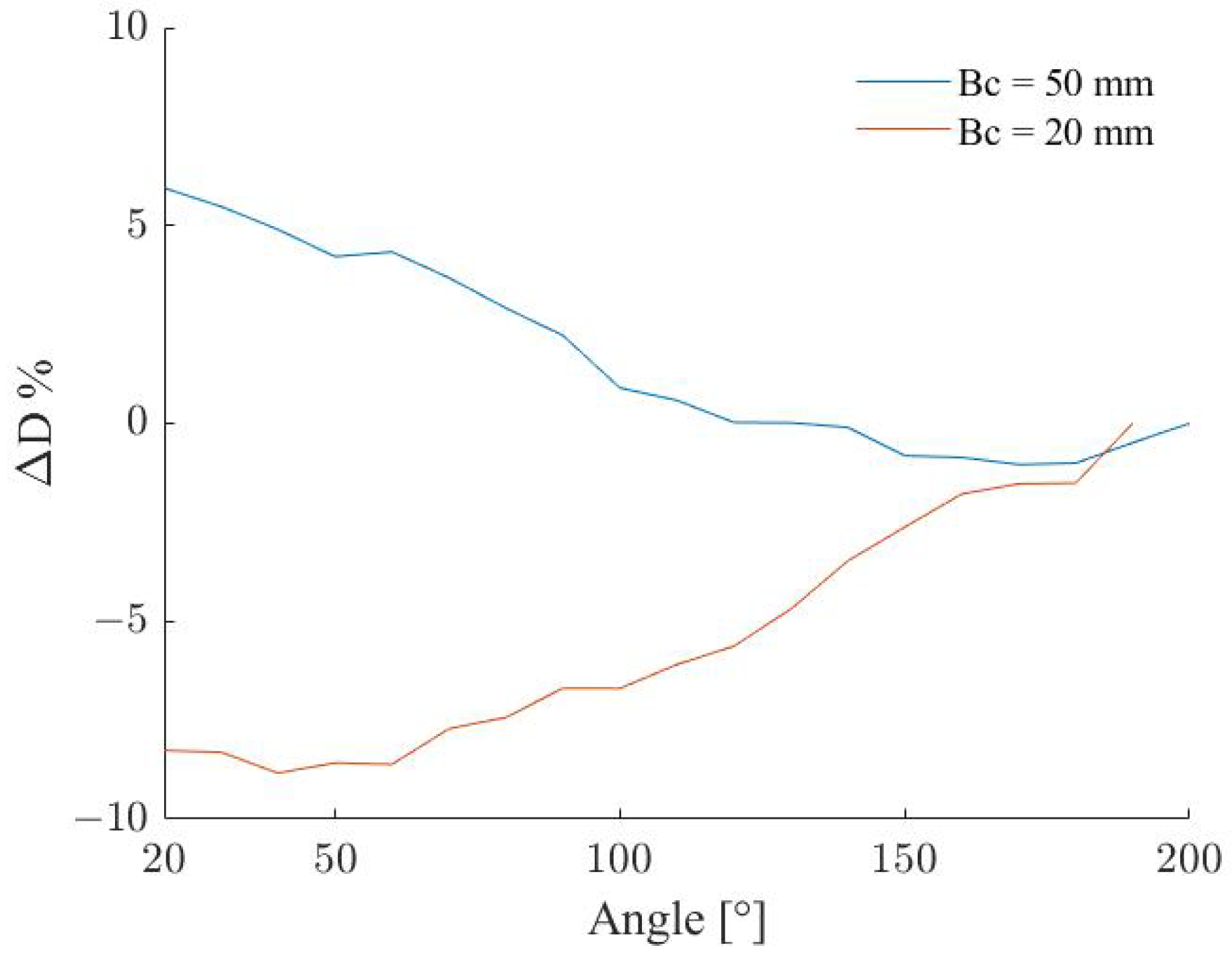
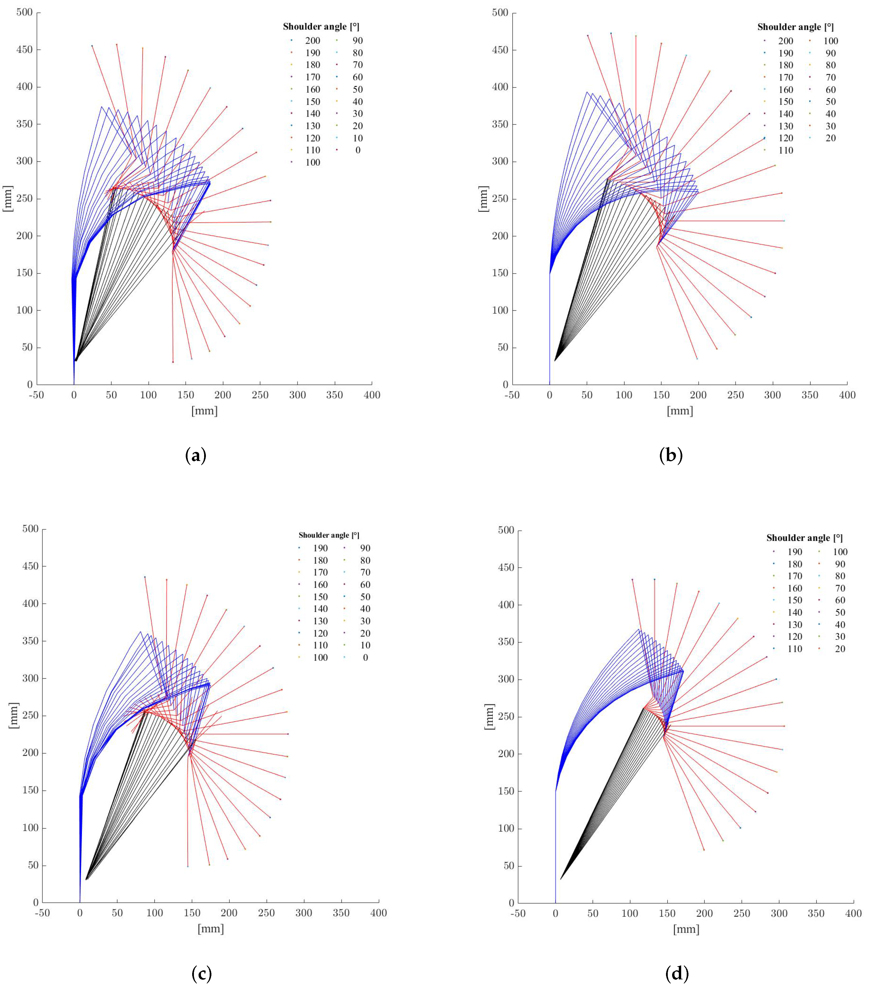
3.2. Exoskeleton Shape Evaluation Results

Figure A1 shows the computed and recorded exoskeleton shapes for different values of the shoulder flexion angles and for the maximum and minimum B c values, i.e., 50 and 20 mm respectively. Figure 7 displays the difference between the computed and recorded deflection as a percentage of the beam length for the two B c values. The difference remains in the range ± 10 % in both cases but with different trends. As Figure 7 reports, the deflection computed is on average larger than the one obtained from the recordings for the same shoulder angles with B c = 50 mm. The difference increased accordingly with the deflection of the beam, which corresponds to a shoulder flexion angle decrease. The opposite happened for a B c = 20 mm with a smaller deflection obtained from the simulated data for the whole flexion range.

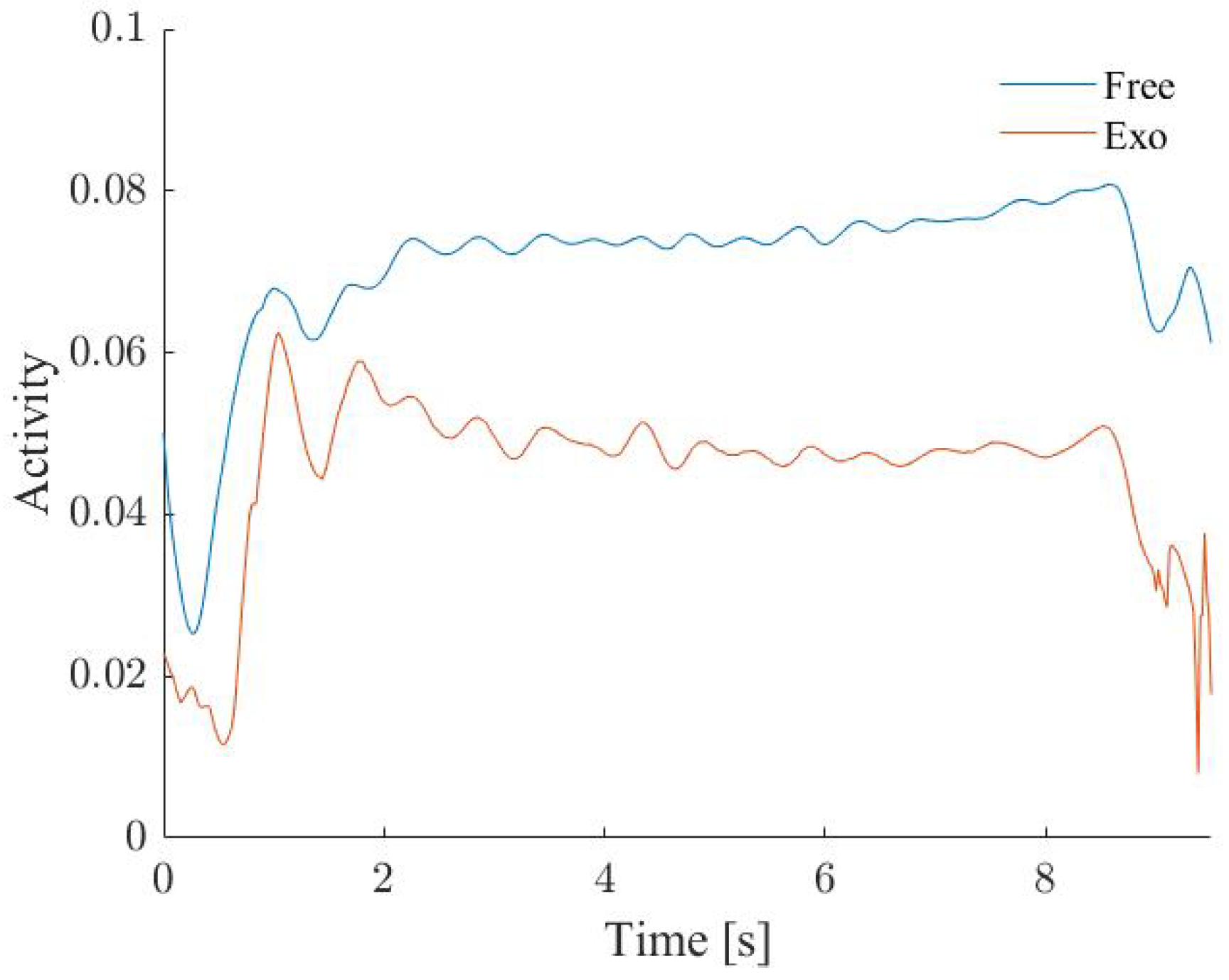
3.3. Musculoskeletal Results

Figure 8 displays the computed trajectories of the two shoulder flexion angles. The two shoulder trajectories have a mean difference of −0.02° (SD 0.07°) and a relative difference of −5.0% (SD 38.01%).
Figure 9 shows the anterior deltoid (AD) activity in the two conditions of the study, the ‘Free’ and ‘Exo’ conditions. The figure shows a reduction in the activation of this muscle during the overhead task. A mean AD activity reduction of 36.01% (SD 10.73%) when the device was present.
The level of support used was the one provided relative to a B c of 35 mm, the same used by the subject of the recording. Another aspect evaluated is the influence of the exoskeleton on the internal shoulder joint forces. Figure 10 shows the absolute value of the shoulder reaction forces in the Glenohumeral joint for the three directions. By using the exoskeleton, a reduction of 41.91% (SD 12.17%) in the Antero-Posterior force and 33.82% (SD 12.25%) for the Distraction Force were obtained during the movement. The force on the infero-superior direction was decreased as well in the initial part of the movement, but it changed direction in the central part of the movement. By analysing its absolute value, a reduction of 4.06% (SD 46.49%) was obtained.

4. Discussion

In this paper, we developed a model of a non-rigid passive exoskeleton for shoulder support. A mathematical model of the device was first created to evaluate the support force profile over the shoulder angles. The computed profiles agreed with the purpose of the exoskeleton to support arm positions of 90° from the standard anatomical position, as the maximum force values were reached for angles between 85–90°. The simulated force value was also in agreement with the one reported by the producer of the device. In particular, the maximum computed support force obtained with a Ba value of 200 mm was equal to the maximum support setting balance reported by the user manual 34.33 N (3.5 kg) [28]. However, the mathematical model showed a limitation in the computation of the bending of the exoskeleton back frames. The difference between the deformation computed from the simulated and from the recorded data was rather large.
The modelling accuracy could be further improved with considerations in the modelling approach. Firstly, we used a simplified 2D model, which led to differences between the device’s modelled and real kinematics. The shoulder of the exoskeleton does not rotate perfectly in the sagittal plane but has an internal-external inclination. In our model, the rotation was on the plane, and that affected the distance between the two connection points of the cable. We used in the model the cable length measured from the device. Therefore, the model computed a bigger deformation to accomplish the higher distance between the cable connection points. The translation from 3D to 2D might have introduced errors in the evaluation of the position of the exoskeleton shoulder rotation centre with respect to the top of the frame elements, as we expressed the position of the centre of rotation in a reference system integral with the back top. The last error source was the one intrinsic to the recordings of the exoskeleton bent position obtained with the motion capture system. We compared the final position of the top of the exoskeleton back frame obtained from the simulations with that of the recording; the measurement error of the latter adds up to the final position error. Marker position errors in the registration cannot be eliminated but only minimised during the calibration process. A 3D modelling should be considered to reduce the position error and better evaluate the exoskeleton deformed shape. A different method from the co-rotational elements, such as the finite element method (FEM), might be used to compute the exoskeleton bending.
Regarding the musculoskeletal simulation, it is possible to see in Figure 8 an overlap of the two curves of the trajectories, which implies kinematic coupling between the two parts of the model. The musculoskeletal simulations showed a general reduction of the AD activation during the performing of the task with the use of the exoskeleton. This result is also in accordance with the findings of previous works [14,22], where a decrease of the activation of this muscle is reported both during musculoskeletal simulations and real tests involving other passive devices during the performing of similar tasks. However, future works should confirm the results presented by directly comparing the muscle activation obtained with the musculoskeletal simulations and real experiments on human subjects.
The evaluation of the effects of the exoskeleton on the joint reaction forces is probably the most interesting aspect of musculoskeletal simulations. Relations between the joint forces, repetitions and MSD are shown in previous studies [31]. A reduction of these forces should be one of the main points taken into consideration while developing an exoskeleton, as a reduction of them might lead lower probability of damaging the human tissues and development of MSD.

5. Conclusions

The mathematical model developed in this study estimated assistive forces that are in accordance with the forces reported by the manufacturer. With the use of musculoskeletal simulations was possible the estimation of joint forces and muscle activities. The results indicate that the exoskeleton can support the human body and reduce these parameters while performing the task. Overall the methodology proposed allows the evaluation of non-rigid exoskeletons in the Anybody ambient, bypassing the limit of the software. With this methodology, it is possible to test different support force profiles developed with mathematical models specifically for a particular task.
Some limitations of this work are noted. As mentioned, the mathematical model should be improved to reproduce the exoskeleton deflection better. Future work should consider a 3D model or another discretization method. The musculoskeletal model has a limitation in the use of a singular revolute joint to reproduce the back bending. Using more than one would have brought a kinematic indeterminacy during the inverse dynamic analysis without driving the other revolute joints. However, using only one revolute joint would not be enough if motion capture data had been used to drive the device directly due to the complex resultant kinematic during the exoskeleton bending. Improvement of the human-exoskeleton model to overcome these limitations will be included in the future work.

Author Contributions

Conceptualization, M.M., A.S.O. and S.B.; methodology, M.M. and S.B.; software, M.M.; validation, M.M.; formal analysis, M.M.; investigation, M.M.; writing—original draft preparation, M.M.; writing—review and editing, M.M., S.B. and A.S.O.; supervision, A.S.O. and S.B. All authors have read and agreed to the published version of the manuscript.

Funding

This work has been supported by the Interreg North Sea Region project EXSKALLERATE EU (www.northsearegion.eu/exskallerate) (accessed on 29 November 2022).

Data Availability Statement

The data presented in this study are available upon request from the corresponding author.

Conflicts of Interest

The authors declare no conflict of interest.

Appendix A

Figure A1. (a) Recorded exoskeleton shape with B c = 50 mm. (b) Computed exoskeleton shape with B c = 50 mm. (c) Recorded exoskeleton shape with B c = 20 mm. (d) Computed exoskeleton shape with B c = 20 mm.
Robotics 11 00147 g0a1

References

  1. Gull, M.A.; Bai, S.; Bak, T. A review on design of upper limb exoskeletons. Robotics 2020, 9, 16. [Google Scholar] [CrossRef] [Green Version]
  2. Wang, T.; Zhang, B.; Liu, C.; Liu, T.; Han, Y.; Wang, S.; Ferreira, J.P.; Dong, W.; Zhang, X. A review on the rehabilitation exoskeletons for the lower limbs of the elderly and the disabled. Electronics 2022, 11, 388. [Google Scholar] [CrossRef]
  3. Hong, M.B.; Kim, G.T.; Yoon, Y.H. ACE-Ankle: A novel sensorized RCM (Remote-Center-of-Motion) ankle mechanism for military purpose exoskeleton. Robotica 2019, 37, 2209–2228. [Google Scholar] [CrossRef]
  4. de Looze, M.P.; Krause, F.; O’Sullivan, L.W. The potential and acceptance of exoskeletons in industry. In Biosystems and Biorobotics; Springer International Publishing: Berlin/Heidelberg, Germany, 2017; Volume 16, pp. 195–199. [Google Scholar] [CrossRef]
  5. Lowe, B.D.; Billotte, W.G.; Peterson, D.R. ASTM F48 formation and standards for industrial exoskeletons and exosuits. IISE Trans. Occup. Ergon. Hum. Factors 2019, 7, 230–236. [Google Scholar] [CrossRef] [PubMed]
  6. Lee, H.; Kim, W.; Han, J.; Han, C. The technical trend of the exoskeleton robot system for human power assistance. Int. J. Precis. Eng. Manuf. 2012, 13, 1491–1497. [Google Scholar] [CrossRef]
  7. Voilqué, A.; Masood, J.; Fauroux, J.C.; Sabourin, L.; Guezet, O. Industrial exoskeleton technology: Classification, structural analysis, and structural complexity indicator. In Proceedings of the 2019 Wearable Robotics Association Conference, WearRAcon 2019, Scottsdale, AZ, USA, 25–27 March 2019; pp. 13–20. [Google Scholar] [CrossRef]
  8. De Looij, I. Modeling and Altering the Force Profile of a Spring-Based Upper Body Exoskeleton with Design Adjustments 2017. TU Delft Repositories. Available online: http://resolver.tudelft.nl/uuid:3267aad6-5f13-4ab8-b7e8-03367e92afe1 (accessed on 29 November 2022).
  9. Pacifico, I.; Molteni, F.; Giovacchini, F.; Vitiello, N.; Crea, S.; Scano, A.; Guanziroli, E.; Moise, M.; Morelli, L.; Chiavenna, A.; et al. An experimental evaluation of the proto-mate: A novel ergonomic upper-limb exoskeleton to reduce workers’ physical strain. IEEE Robot. Autom. Mag. 2020, 27, 54–65. [Google Scholar] [CrossRef]
  10. Balser, F.; Desai, R.; Ekizoglou, A.; Bai, S. A novel passive shoulder exoskeleton designed with variable stiffness mechanism. IEEE Robot. Autom. Lett. 2022, 7, 2748–2754. [Google Scholar] [CrossRef]
  11. Bosch, T.; van Eck, J.; Knitel, K.; de Looze, M. The effects of a passive exoskeleton on muscle activity, discomfort and endurance time in forward bending work. Appl. Ergon. 2016, 54, 212–217. [Google Scholar] [CrossRef]
  12. Ma, L.; Chablat, D.; Bennis, F.; Zhang, W. Dynamic muscle fatigue evaluation in virtual working environment. Int. J. Ind. Ergon. 2009, 39, 211–220. [Google Scholar] [CrossRef] [Green Version]
  13. Kim, S.; Nussbaum, M.A.; Mokhlespour Esfahani, M.I.; Alemi, M.M.; Alabdulkarim, S.; Rashedi, E. Assessing the influence of a passive, upper extremity exoskeletal vest for tasks requiring arm elevation: Part I—“Expected” effects on discomfort, shoulder muscle activity, and work task performance. Appl. Ergon. 2018, 70, 315–322. [Google Scholar] [CrossRef]
  14. Hyun, D.J.; Bae, K.H.; Kim, K.J.; Nam, S.; Lee, D.-h. A light-weight passive upper arm assistive exoskeleton based on multi-linkage spring-energy dissipation mechanism for overhead tasks. Robot. Auton. Syst. 2019, 122, 103309. [Google Scholar] [CrossRef]
  15. de Vries, A.W.; Krause, F.; de Looze, M.P. The effectivity of a passive arm support exoskeleton in reducing muscle activation and perceived exertion during plastering activities. Ergonomics 2021, 64, 712–721. [Google Scholar] [CrossRef] [PubMed]
  16. Schmalz, T.; Schändlinger, J.; Schuler, M.; Bornmann, J.; Schirrmeister, B.; Kannenberg, A.; Ernst, M. Biomechanical and metabolic effectiveness of an industrial exoskeleton for overhead work. Int. J. Environ. Res. Public Health 2019, 16, 4792. [Google Scholar] [CrossRef] [PubMed] [Green Version]
  17. Moyon, A.; Petiot, J.F.; Poirson, E. Investigating the effects of passive exoskeletons and familiarization protocols on arms-elevated tasks. In Proceedings of the Human Factors and Ergonomics Society Europe Chapter 2019 Annual Conference, Seattle, WA, USA, 28 October–1 November 2019. [Google Scholar]
  18. Spada, S.; Ghibaudo, L.; Gilotta, S.; Gastaldi, L.; Cavatorta, M.P. Analysis of exoskeleton introduction in industrial reality: Main issues and EAWS risk assessment. Adv. Intell. Syst. Comput. 2018, 602, 236–244. [Google Scholar] [CrossRef]
  19. Settembre, N.; Maurice, P.; Paysant, J.; Theurel, J.; Claudon, L.; Kimmoun, A.; Levy, B.; Hani, H.; Chenuel, B.; Ivaldi, S. The use of exoskeletons to help with prone positioning in the intensive care unit during COVID-19. Ann. Phys. Rehabil. Med. 2020, 63, 379–382. [Google Scholar] [CrossRef]
  20. Spada, S.; Ghibaudo, L.; Carnazzo, C.; Di Pardo, M.; Chander, D.S.; Gastaldi, L.; Cavatorta, M.P. Physical and virtual assessment of a passive exoskeleton. Adv. Intell. Syst. Comput. 2019, 825, 247–257. [Google Scholar] [CrossRef]
  21. Fournier, B.N.; Lemaire, E.D.; Smith, A.J.; Doumit, M. Modeling and Simulation of a Lower Extremity Powered Exoskeleton. IEEE Trans. Neural Syst. Rehabil. Eng. 2018, 26, 1596–1603. [Google Scholar] [CrossRef]
  22. Fritzsche, L.; Galibarov, P.E.; Gärtner, C.; Bornmann, J.; Damsgaard, M.; Wall, R.; Schirrmeister, B.; Gonzalez-Vargas, J.; Pucci, D.; Maurice, P.; et al. Assessing the efficiency of exoskeletons in physical strain reduction by biomechanical simulation with AnyBody Modeling System. Wearable Technol. 2021, 2, e6. [Google Scholar] [CrossRef]
  23. Blanco, A.; Catalán, J.M.; Díez, J.A.; García, J.V.; Lobato, E.; García-Aril, N. Electromyography assessment of the assistance provided by an upper-limb exoskeleton in maintenance tasks. Sensors 2019, 19, 3391. [Google Scholar] [CrossRef] [Green Version]
  24. Tröster, M.; Wagner, D.; Müller-Graf, F.; Maufroy, C.; Schneider, U.; Bauernhansl, T. Biomechanical model-based development of an active occupational upper-limb exoskeleton to support healthcare workers in the surgery waiting room. Int. J. Environ. Res. Public Health 2020, 17, 5140. [Google Scholar] [CrossRef]
  25. Barjuei, E.S.; Caldwell, D.G.; Ortiz, J. Bond graph modeling and kalman filter observer design for an industrial back-support exoskeleton. Designs 2020, 4, 53. [Google Scholar] [CrossRef]
  26. Yan, Y.; Chen, Z.; Huang, C.; Guo, Q. Modelling and analysis of coupling dynamics of swinging a lower limb exoskeleton. Nonlinear Dyn. 2022, 1–22. [Google Scholar] [CrossRef]
  27. Gull, M.A.; Bak, T.; Bai, S. Dynamic modeling of an upper limb hybrid exoskeleton for simulations of load-lifting assistance. Proc. Inst. Mech. Eng. Part C J. Mech. Eng. Sci. 2022, 236, 2147–2160. [Google Scholar] [CrossRef]
  28. Skelex 360 Manual 2019. Available online: https://www.skelex.com/wp-content/uploads/2019/08/Skelex-360-User-manual-V1.1-29-03-2019.pdf (accessed on 29 November 2022).
  29. Taghvaeipour, A.; Kermanian, A.; Kamali, A. On the corotational beam element formulation in large deformation analysis. Iran. J. Mech. Eng. Trans. ISME 2018, 19, 94–115. [Google Scholar]
  30. Felippa, C.A.; Haugen, B. A unified formulation of small-strain corotational finite elements: I. Theory. Comput. Methods Appl. Mech. Eng. 2005, 194, 2285–2335. [Google Scholar] [CrossRef]
  31. Gallagher, S.; Schall, M.C. Musculoskeletal disorders as a fatigue failure process: Evidence, implications and research needs. Ergonomics 2016, 60, 255–269. [Google Scholar] [CrossRef]
Figure 1. The Skelex 360 passive exoskeleton.
Robotics 11 00147 g001
Figure 2. Modeling of large deflection beam with i elements. (a) Undeformed and (b) deformed beam shapes. In this work, we take i = 10.
Robotics 11 00147 g002
Figure 3. Scheme of gravity balance with Skelex 360 passive exoskeleton.
Robotics 11 00147 g003
Figure 4. Marker position on the exoskeleton for shape evaluation. This flexible beam was disconnected from Skelex 360 for validation of the deflection model.
Robotics 11 00147 g004
Figure 5. The human-exoskeleton model in AnyBody.
Robotics 11 00147 g005
Figure 6. Force shapes for different shoulder angles.
Robotics 11 00147 g006
Figure 7. Deflection difference as a percentage of the beam length for two B c length values.
Robotics 11 00147 g007
Figure 8. Trajectories of the two shoulder flexion angles.
Robotics 11 00147 g008
Figure 9. Anterior deltoid activity in two conditions: with (Exo) and without (Free) the exoskeleton.
Robotics 11 00147 g009
Figure 10. Glenohumeral internal forces in two conditions, with and without the exoskeleton. (a) Infero-Superior force; (b) Distraction force; (c) Antero-Posterior force.
Robotics 11 00147 g010
Publisher’s Note: MDPI stays neutral with regard to jurisdictional claims in published maps and institutional affiliations.

