Article

Three-Dimensional Printing of Cylindrical Nozzle Elements of Bernoulli Gripping Devices for Industrial Robots

by
Roman Mykhailyshyn
1,2,*,
František Duchoň
3,
Mykhailo Mykhailyshyn
4 and
Ann Majewicz Fey
5,6
1
Texas Robotics, College of Natural Sciences and the Cockrell School of Engineering, The University of Texas at Austin, Austin, TX 78712, USA
2
Department of Automation of Technological Processes and Manufacturing, Ternopil Ivan Puluj National Technical University, 46001 Ternopil, Ukraine
3
Institute of Robotics and Cybernetics, Slovak University of Technology in Bratislava, 81219 Bratislava, Slovakia
4
Department of Information Science and Mathematical Modeling, Ternopil Ivan Puluj National Technical University, 46001 Ternopil, Ukraine
5
Walker Department of Mechanical Engineering, The University of Texas at Austin, Austin, TX 78712, USA
6
Department of Surgery, UT Southwestern Medical Center, Dallas, TX 75390, USA
*
Author to whom correspondence should be addressed.
Robotics 2022, 11(6), 140; https://doi.org/10.3390/robotics11060140
Submission received: 24 October 2022 / Revised: 17 November 2022 / Accepted: 29 November 2022 / Published: 3 December 2022
(This article belongs to the Special Issue Advanced Grasping and Motion Control Solutions)

Abstract

:
The application of additive technologies, namely, fused deposition modeling, is a new reality for prototyping gripping devices of industrial robots. However, during 3D printing of holes and nozzle elements, difficulties arise with reducing their diameter. Therefore, this article conducts a comprehensive study of the Bernoulli gripping device prototype with a cylindrical nozzle, manufactured by fused deposition modeling 3D printing. The three main reasons for reducing the diameter of the gripper nozzle after printing were due to the poor-quality model, excessive extrusion of plastic in the middle of the arc printing path, and linear shrinkage of printing material after cooling. The proposed methodology consisted of determining the three coefficients that allowed the determination of the diameter of the designed nozzle. The use of air pressure distributions on the surface of the manipulation object, and lifting forces of gripping devices with different 3D printing layer heights were found. It was experimentally determined that as the height of the printing layer increased, the lifting force decreased. This was due to the formation of swirls due to the increased roughness of the grip surface. It was proven that as the height between the manipulation object and the grip increased, the effect of surface roughness on the lifting force decreased, resulting in an increase in the lifting force. Determination of the rational operating parameters of gripping devices manufactured by 3D printing from the point of view of maximum lifting force, were determined.

1. Introduction

At present, manufacturing additive technology is gaining great popularity [1,2,3,4,5,6,7,8,9,10,11,12,13], and 3D printing is being applied not only to production units but also as a means of production [14]. In particular, the authors of [8] concluded that most companies choose additive manufacturing (AM) to save time and costs, which are most relevant when producing new products and small batches. Only a small percentage of companies have chosen AM for reasons of environmental friendliness, in comparison with classic production methods. In addition, the authors noted an increase in the innovative component for the introduction of AM in companies, and a decrease in the impact of the supply chain on production capacities. Therefore, the introduction of additive manufacturing in various industries is a current topic and further research is warranted. Currently, many researchers are conducting research related to the optimization and improvement of the quality of 3D printing [15,16,17]. As a separate direction, we can single out studies that focus on evaluating the impact of printing parameters on the dimensions [18,19] and surface quality [20] of this prototype.
The use of AM has become widespread in the field of robotics [21,22,23,24,25,26,27,28]. In addition, it should be noted that there is an increasing use of 3D printing in the construction of gripping devices for industrial robots [29,30,31,32,33,34,35,36,37,38,39,40,41,42,43,44,45,46,47,48,49,50,51]. The papers [22,23,26,37] describe the process of 3D printing and manufacturing of mechanical gripping devices by FDM printing. Among other important directions is the production of soft gripping devices using additive manufacturing [24,25,27,28,29,30,31,32,33,36,38,39,40,41]. A new important direction of using additive technologies in the manufacture of grippers is the use of magnetic materials during 3D printing [34]. It should be noted that 3D printing is less useful for pneumatic gripping devices of industrial robots. However, with the active development and introduction of flexible materials into 3D printing, it has become possible to print suction cups for pneumatic grips of different shapes [52,53,54,55] (Figure 1).
One promising type of pneumatic gripper is the jet gripper [56,57,58,59,60,61,62,63,64,65,66,67,68,69,70,71]. Jet grippers have completely different characteristics than vacuum grips due to the effect of raising the force that occurs when the air jet flows around the object of manipulation of the developed nozzle elements [47]. The advantages of jet gripping devices include the high accuracy of basing objects [52,53,54]; the gripping of flexible objects [56,57,58], brittle objects [62,64] and objects heated to high temperatures; good dynamic characteristics [59,61]; design simplicity [60]; and durability. Since these grippers have a high air flow rate, scientists pay considerable attention to optimizing the motion parameters of gripping systems and their dynamics using jet grippers [72,73,74,75,76,77,78,79,80,81,82,83,84,85]. Often, jet grips with a cylindrical and annular nozzle are called Bernoulli gripper devices (BGD), since the description of power characteristics occurs using Bernoulli’s law. Enthusiasts of 3D printing tried to print BGD using fused deposition modeling (FDM) [86] printing technology, but it had low lift and, depending on the plastic blowing system (when 3D printing), there may have been problems with the vision of the nozzle elements. Using another photopolymer (SLA) 3D printing technology, the authors of [87] created a Bernoulli grip with an annular nozzle for tissue capture during laparoscopy. However, FDM 3D printing is the most available and favorable technology in terms of economic feasibility of prototyping and production, to date. Therefore, the study of the technology and the justification of the printing parameters of the nozzle elements of Bernoulli’s gripping devices is a relevant topic.
Little attention has been paid to FDM 3D printing for the manufacture of pneumatic gripping devices of industrial robots, in the analysis of the use of additive manufacturing (AM). The issue of FDM 3D printing holes and nozzle elements of invaders has only been partially considered. At the same time, the thickness of the nozzle wall and shrinkage of the material were considered. The method proposed in this paper will allow a determination of the preliminary diameter of the model nozzle in order to provide the necessary diameter after 3D printing. In particular, no studies have yet been conducted on the effect of printing parameters on the power characteristics of Bernoulli pneumatic gripping devices. However, the 3D printing parameters will critically affect the power characteristics of gripping devices, which suggests that such investigation is in urgent need. Therefore, the authors of this paper have conducted, for the first time, a study of the effect of printing parameters on the power characteristics of Bernoulli gripping devices with a cylindrical nozzle, which allows a justification of the rational parameters of FDM 3D printing of gripping devices with cylindrical nozzle elements and their performance characteristics.

2. Materials and Methods

The principle of the BGD operation was as follows. Compressed air from the Bernoulli chamber (label 1, Figure 2), through the cylindrical nozzle (label 2) with radius rn followed the gap between its end surface and the surface of the object of manipulation (OM) (label 3). At the same time, at radius rn, at hc < rn/2, the flow experienced its greatest constriction. At the point of greatest constriction, at excessive gripping power pressures of more than 30 kPa, the flow reached a critical speed equal to the speed of sound, for those conditions. As a result of the further increase in area of radial flow, its supersonic velocity increased, and static pressure on the surface of the OM decreased to a lower atmospheric value. At some distance from the center of the nozzle, a sharp braking of the supersonic flow occurred, followed by its transition to the subsonic flow, which was accompanied by a pressure jump. As a result of further expansion, the rate of subsonic flow dropped, and the static pressure in the gap smoothly increased to the value of atmospheric pa. The effect of the vacuum on the surface of the OM led to its levitation. Lateral displacement of the OM prevented abutments (label 4).
The performance characteristics of the BGD depend on the parameters of the power supply and those geometric parameters affecting the formation of air flow in the radial gap, in particular, the radius of the nozzle rn, the roughness of the nozzle surface and the active grip surface, the external grip radius rg, and the distance hc from the nozzle edge to the OM.
During the 3D printing of a BGD using FDM technology [88], deformations of the printing model occur, associated with the printing process itself. Since the main element from the point of view of making a BGD is the gripping device’s nozzle, with 3D printing of small diameter holes by the finished part, many deviations can occur relating to the 3D model quality (STL file), over-extrusion, vertical seam that passes through the hole, total shrinkage of the model and printing parameters (fluidity, printing speed, grade height, etc.). All these listed parameters will affect the diameter of the printed nozzle and its geometry, which will affect the swirls formed from the suboptimal geometry of the nozzle and the lifting force of the Bernoulli gripping devices. The main three reasons for reducing the diameter of the gripping device nozzle after 3D printing were identified as: poor 3D STL model quality, excessive extrusion of plastic in the middle of the arc printing path, and linear shrinkage of the filament material after cooling of the object. The proposed methodology consisted of determining the three coefficients that allow the determination of the diameter of the designed nozzle (Figure 3).
The method of determining the diameter of the designed nozzle was based on the step-by-step determination of the three compensation coefficients of the nozzle diameter. To determine the next coefficient, the already-adjusted nozzle diameter was used, which allowed the rejection of the influence of these effects on each other. The proposed method had two main assumptions: (1) the cylindrical nozzle was placed perpendicular to the printing plane, and, (2) printing took place in a closed-type 3D printer, which prevented the influence of external parameters on the printing process.

3. Results and Discussion

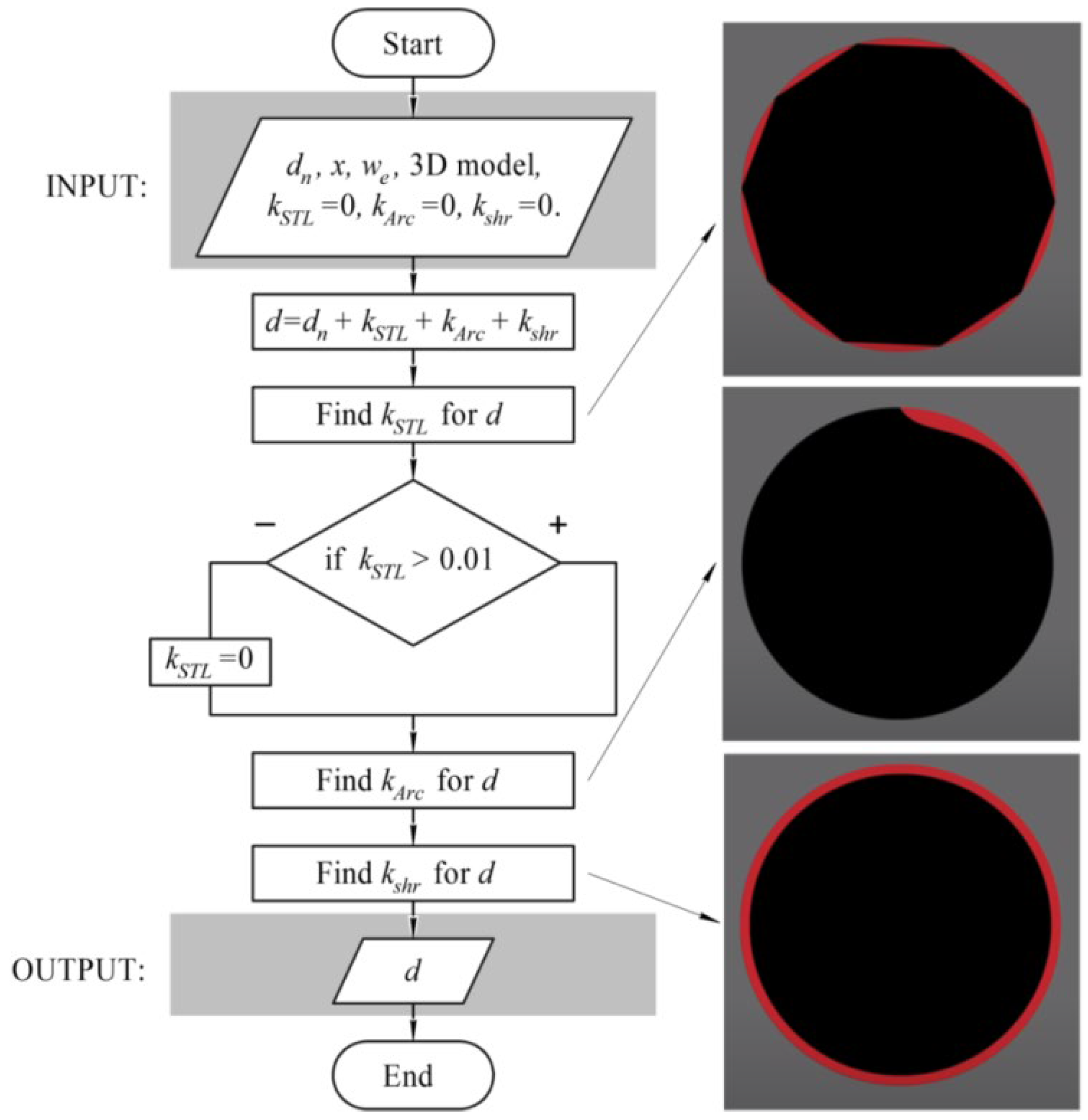
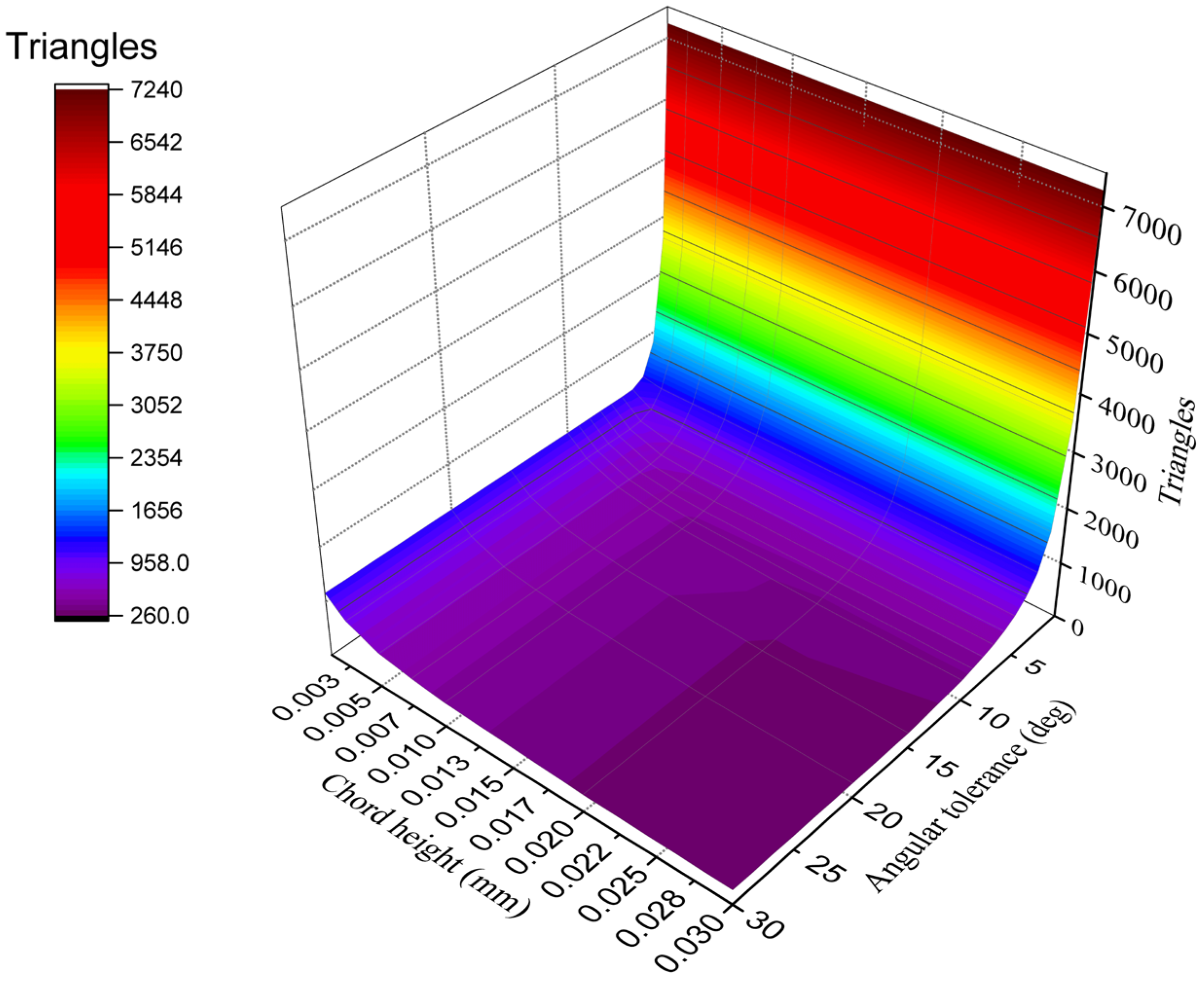
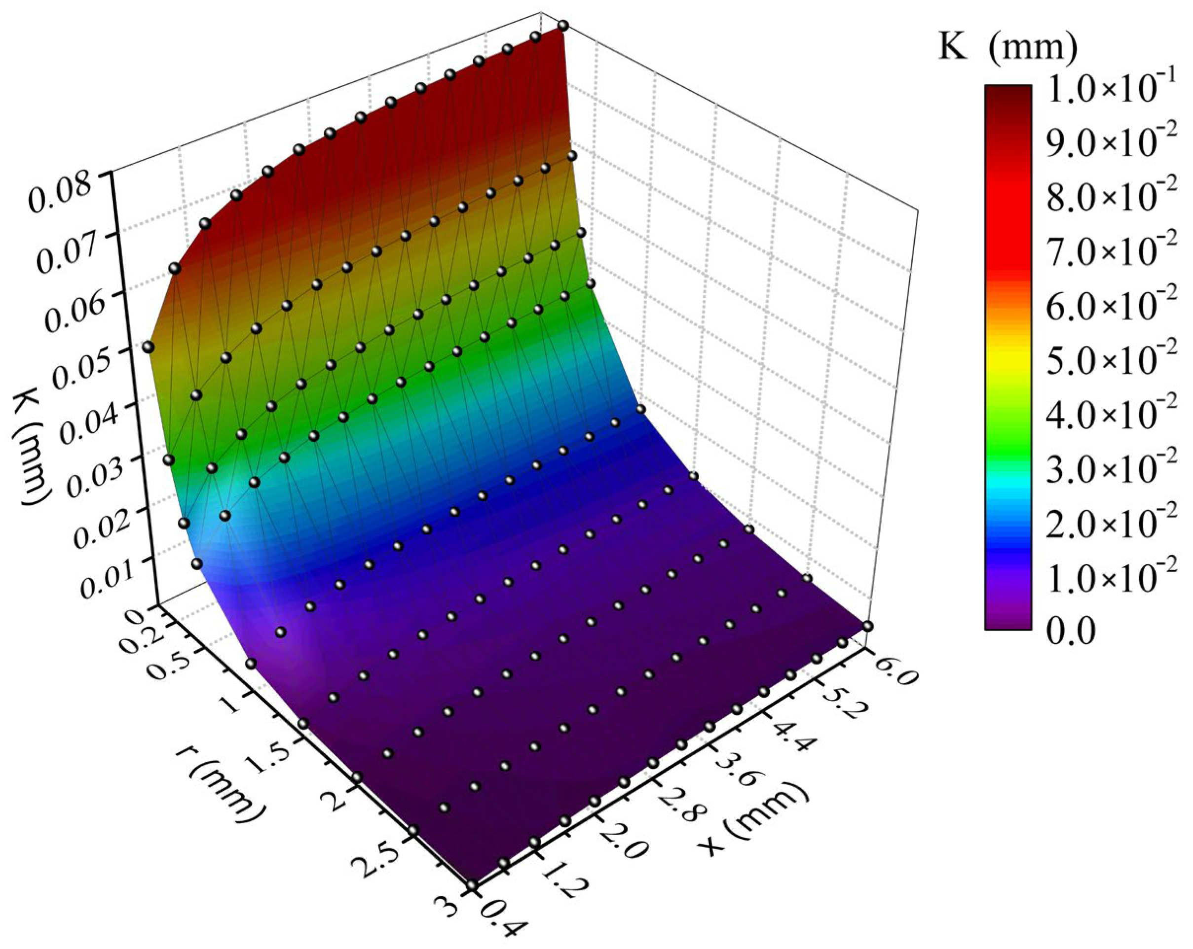
3.1. Coefficient Quality of Model

Before printing the Bernoulli gripping devices, it was necessary to investigate the effect of 3D model parameters on the real geometric parameters obtained during the 3D printing of nozzle elements. When preparing a 3D model for printing, it is stored in STL (standard tessellation language) format. This is the standard format for all software packages (slicers) that prepare the G-code for managing the 3D printer. To prepare the 3D model of Bernoulli gripping devices and other investigated elements, the software package SolidWorks is used. When a model is saved to STL format, a CAD (computer-aided design) 3D model is saved to the 3D model, which is described by triangles of various shapes. In the software package SolidWorks, as in all other software packages, there are two parameters that are responsible for the quality of the stored 3D model in the STL format (chord height and α angular tolerance). Chord height is the maximum distance that software will create between the surface of the original 3D model and the surface of the STL file. Angular tolerance limits the angle between the normals of adjacent triangles. The default value is often 15 degrees, and some programs specify this tolerance as 0 to 1. To study the effect of these parameters on the 3D of hands, we created a separate model consisting of a nozzle element with a diameter of dn = 6 mm (Figure 4).
The 3D model of the nozzle had a longitudinal element, created to provide uniform cooling of a detail during 3D printing. As for the press, the 3D printer Wanhao Duplicator 6 was used [89], which was equipped with blowing of a detail only on one hand. In addition, the longitudinal member was conveniently used to contain nozzle parameters during measurement, and denote printing parameters for further investigation. To illustrate the effect of parameters, we considered the effect of changing the parameters, chord height and angular tolerance, on the geometry of the STL model (Figure 5).
Figure 5 clearly shows that the number of triangles in the STL file describes the 3D model of the nozzle, which was more influenced by angular tolerance. Since the maximum variation in the number of triangles from which the STL file was formed was answered by a chord height of 0.03 mm, the nozzle models were later printed (Figure 4) with this chord height value. Printing was performed with this constant parameter, as shown in Table 1. The preparation of the G-code for printing was performed using the Wanhao Cura 18.04 software package, and the printing itself was conducted with a closed thermal camera.
Dependencies were defined on the effect of the angular tolerance parameter on the diameter of the printed nozzle at the given CAD model diameter of 6 mm (Figure 6). Measurements were carried out with a caliper, with an accuracy of 0.005 mm in different places 10 times, for each of the five samples with the same model parameters.
From Figure 6, it is apparent that when the angular tolerance decreased to 0.5 degrees, the nozzle diameter increased to an average of 5.71 mm, which was 0.13 mm less than at an angular tolerance of 30 degrees. This was due to the fact that at an angular tolerance of 30 degrees, the number of triangles from which the STL file will consist, was 264; and at 0.5 degrees, the number of triangles was 7236. In addition, it can be seen that there were average nozzle diameter values that matched, for example, at angular tolerances of 20 and 30 degrees, and at 6 and 7 degrees. This trend was due to the fact that at these angular tolerance values, the number of triangles that made up the STL model was equal to or different by only a few triangles. The G-code created by the Cura program in preparation for printing the nozzle with STL files at an angular tolerance of 30 and 0.5 degrees, was considered. In particular, from the entire program code, a third layer was selected → the extruder center path when printing the outer wall of the nozzle opening → and for this trajectory, the extreme instructions for moving the extruder along the Y axis (Table 2).
Under ideal conditions, the diameter of the printed nozzle should be equal to:
d = Y m a x Y m i n w e ,
where Ymax is the maximum value of the position of the extruder along the Y axis when 3D printing the outer layer of the nozzle opening wall, Ymin is the minimum value of the position of the extruder along the Y axis when 3D printing the outer layer of the nozzle opening wall, and we is the extrusion width set during printing (in our case, 0.4 mm).
For G-codes obtained for an angular tolerance of 30 degrees, the diameter was d = 5.96 mm, and for an angular tolerance of 0.5 degrees, then d = 5.999 mm. From this, it was concluded that when creating an STL file for 3D printing, it is not recommended to use the standard parameters that are embedded into the CAD software. The parameters must be configured manually, and the angular tolerance selected as the minimum value to ensure the maximum quality of nozzle and other elements of the model. This will avoid use of the nozzle diameter compensation factor in the future. In case it is not possible, in the STL model, to adjust the angular tolerance and/or chord height to increase the quality of the 3D printing, it is recommended to increase the diameter of the nozzle hole using the STL model quality compensation factor:
k S T L = d n Y m a x Y m i n + X m a x X m i n 2 + w e ,
where dn is the nominal diameter of an opening of a nozzle of capture that was set in the CAD model; Xmax, Ymax represent the maximum value of provision of an extruder on axis X and Y, respectively, at the 3D printing of an external layer of a wall of an opening of a nozzle; and Xmin, Ymin represent the minimum value of provision of an extruder on axis X and Y, respectively, at the 3D printing of an external layer of a wall of an opening of a nozzle.
Another solution to the poor quality STL model of the finished product to be printed is the use of Arc Welder Plugin [91], which allows the Slicers program to replace linear interpolation commands G1 with arc interpolation commands G2 and G3. Using this plugin has the advantages of reducing the size of the G-code file by replacing many linear commands with one arc, in addition to a smooth and fast extruder movement during printing. However, the use of this plugin has been little studied, and at this stage does not work stably with STL models of different quality.

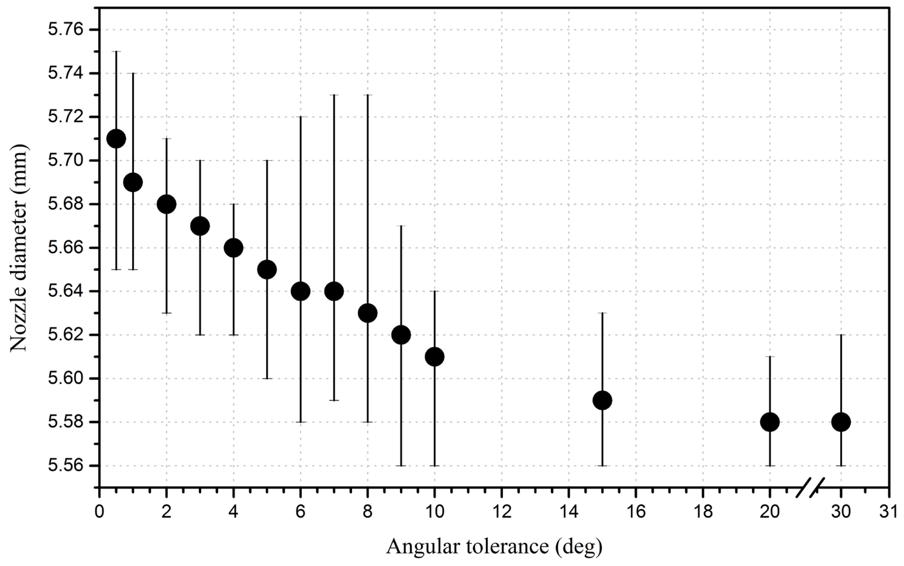
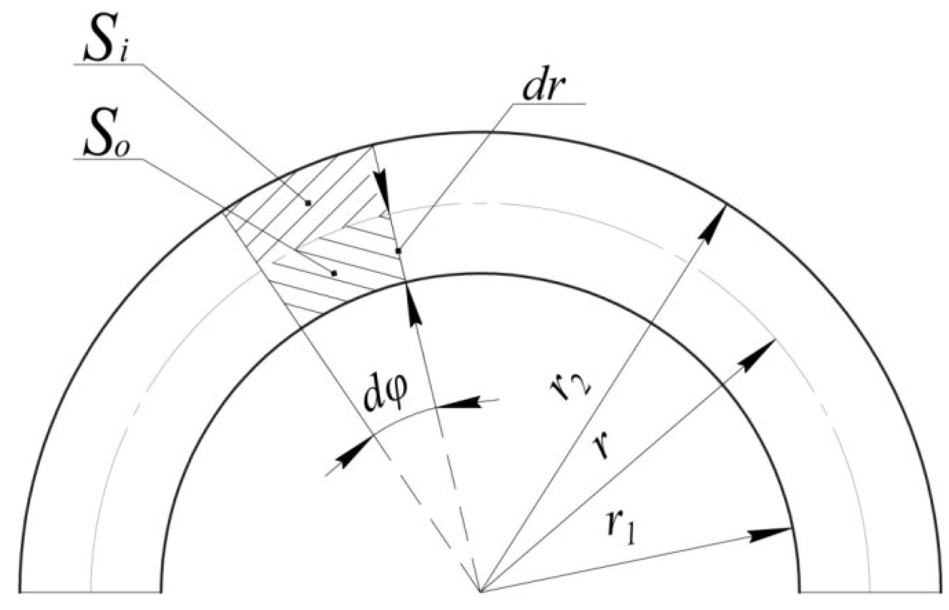
3.2. Coefficient Overexstrusion under Arc Path Motion

In the 3D printing of Bernoulli grippers, nozzle elements with a diameter of less than 8 mm are normally used. This is due to a critical increase in the consumption characteristics of compressed air with large nozzle diameters of gripping devices. When the 3D printer extrudes a layer of plastic in a straight line, it evenly distributes it on both sides of the center of the extruder nozzle (Figure 7), however, when moving along an arc path, an undesirable effect occurs and more material is presented inside the arc than necessary, and, vice versa, less material on the outside of the arc (Figure 8).
This problem (Figure 8) when printing holes is usually solved experimentally, or simplified equations or plugins are used, proposed by manufacturers of various software. For example, resource RepRap [92] offers the Arc Compensation algorithm, which calculates the decrease in the diameter of the hole by comparing the areas, and fills the hole with an extruder in a straight and arc path. In accordance with this algorithm, an equation was proposed to calculate the radius of passage of the center of the extruder, taking compensation into account:
r = w e + w e 2 + 4 R 2 2 ,
where R is the radius of the required hole.
However, this algorithm was calculated for only one pass and did not allow the determination of the motion parameters of the extruder when it was necessary to form the hole wall as a result of several passes. Therefore, we proposed a method for calculating the displacement of the inner and outer radius of the extruded plastic layer when 3D printing along an arc path, as shown in Figure 9.
When the extruder passes along an arc trajectory with a radius r of the path rdφ for the same time, the areas So and Si are filled with plastic:
S o = r 2 r d φ r + 1 2 ( r 2 r ) 2 d φ = 1 2 r 2 2 r 2 d φ ,
S i = r 1 r r 1 d φ + 1 2 ( r r 1 ) 2 d φ = 1 2 r 2 r 1 2 d φ ,
where r1 is the internal radius of the extruded arc, r is the radius of movement of the center of the extruder, and r2 is the external radius of the extruded arc.
Since plastic is evenly extruded through the extruder on both sides relative to its radius of motion r, and the outer and inner area of the extruded plastic is filled at the same time, these areas are level:
S o = S i 2 r 2 = r 1 2 + r 2 2 .
The total area of the extruded plastic when moving in an arc is equal:
S t = S o + S i = 1 2 r 2 2 r 1 2 d φ .
If the extruder moves with some speed v, then:
v = r d φ d t d φ = v d t r ,
S t = 1 2 r 2 2 r 1 2 v d t r ,
Therefore, with uniform movement of the extruder along a rectilinear trajectory, the area which the extruder fills is equal to:
S l = w e v d t ,
where v is the extruder speed, t is the extruder move time, and we is the extrusion width.
During 3D printing, the printer extrudes the same amount of plastic, both in rectilinear and arc motions, so that the areas St and Sl can be equated and a dependence can be obtained:
2 w e r = r 2 2 r 1 2 .
Using dependences (6) and (11), a system of equations is obtained:
r 2 2 + r 1 2 = 2 r 2 ; r 2 2 r 1 2 = 2 w e r .
From the system of Equation (12), we can determine two radii by specifying the third. For example, setting the radius of the trajectory of the extruder r we find:
r 2 = r r + w e , r 1 = r r w e .
If we specify the radius r1 = R, then we find Equation (3), and if we specify the radius r2 for the radius r we obtain:
r = w e 2 + w e 2 4 + r 2 2 .
However, the above model describes the radius offset of only one layer of extruded plastic, and FDM printing practically never uses walls in one layer of material. Therefore, we proposed Algorithm 1 for calculating the arc compensation coefficient, determining the necessary increase in the hole radius to provide a given radius during design. In this case, during the operation of Algorithm 1, the displacement of the inner layer of the hole for different wall thickness was calculated.
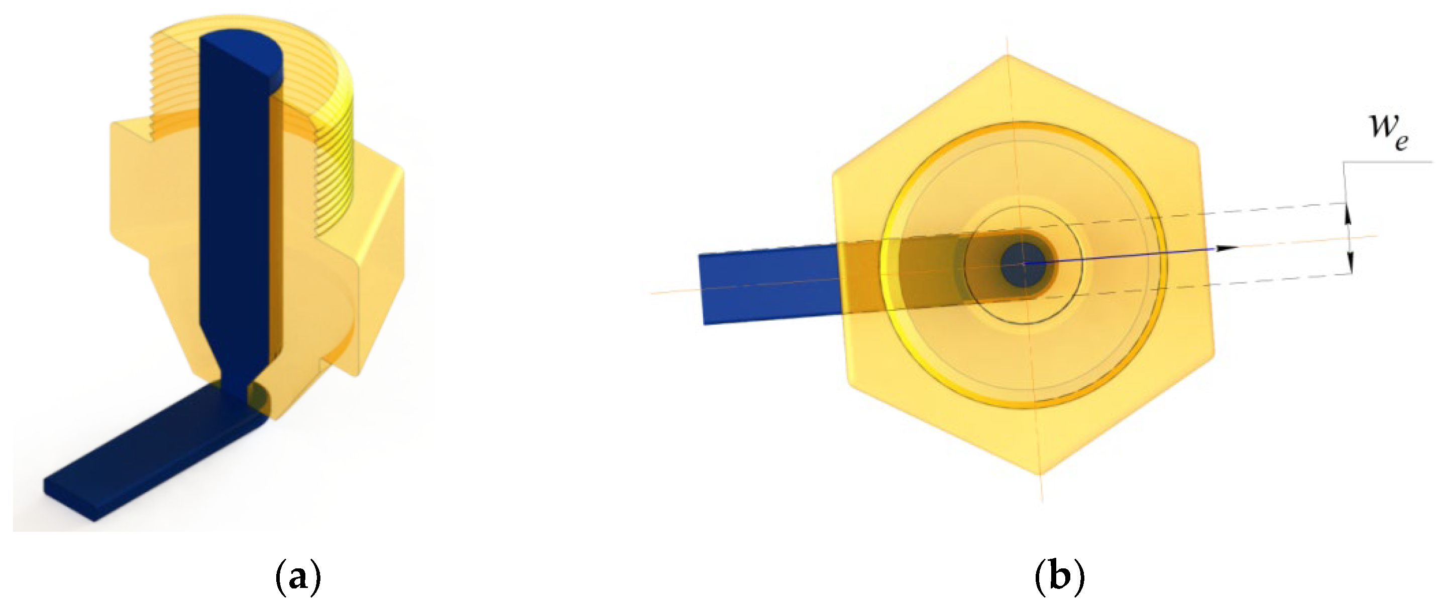
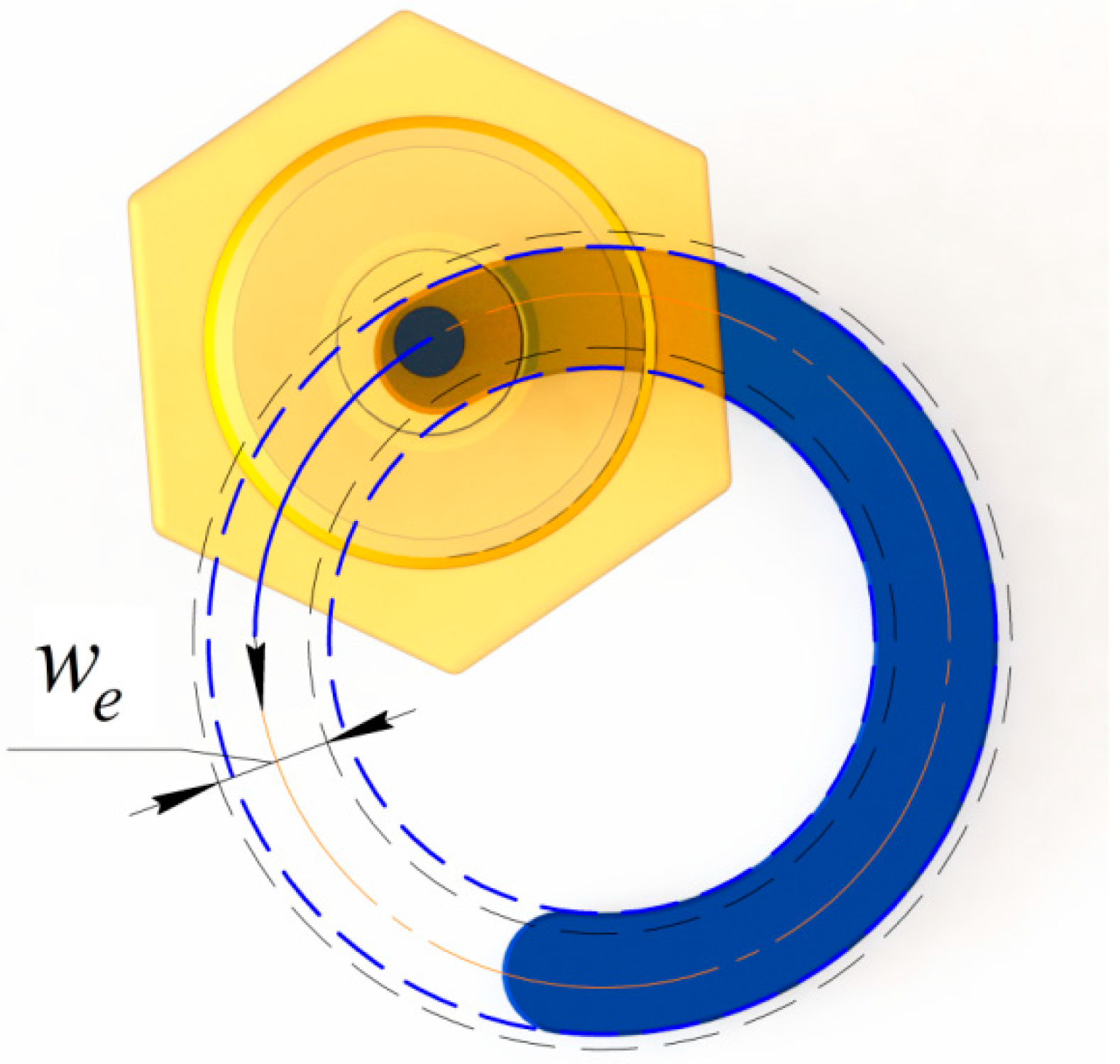
Algorithm 1 The displacement of the inner layer of the hole for different wall thickness
1: INPUT: r1, x, we
2: n floor x + 0.1 / w e
3: FindF(n, x)
4:     r 2 0 r 1 + x
5:     for   i 1 n
6:         r i w e / 2 + w e 2 / 4 + r 2 i 1 2
7:         r 2 i r i ( r i w e )
8:     r 2 n r 1
9: ax, b x + w e , eps ← 10−10
10: Findr3
11:     while   F n , c > e p s
12:        c a + b / 2
13:        if   F n , a F n , c < 0   then
14:          b c
15:        else
16:          a c
17:        c
18:  k A r c 2 c x
Using Algorithm 1, the effect of the radius r of the printed cylindrical nozzle and the width of the wall x of this nozzle on the arc compensation factor of the nozzle radius were calculated (Figure 10).
As shown in Figure 10, the nozzle radius compensation factor was critical only when the nozzle radius was less than 1 mm, and practically did not change after reaching a wall thickness of 2 mm. This was due to the fact that at a radius of more than 3 mm, the coefficient of compensation of the radius of one layer of extruded plastic was less than 0.01 mm. The effect of nozzle wall thickness x on nozzle hole diameter in Algorithm 1, at a mm radius, was considered (Figure 11).
To compare the effect of the reduction in the diameter of the printing nozzle from the arc motion of the extruder and the experimental data on the zero point, the diameter at the wall thickness was set as x = 0.4 mm (Figure 11a). Using Algorithm 1, it was possible to derive the value of the change in the diameter of the nozzle hole formed due to the arc motion of the extruder, and compare the obtained data with the experimental ones (Figure 12).
As shown in Figure 12, the change in the diameter of the print nozzle depended on the arc motion of the extruder by only 31…33% and this percentage depended only on the radius and thickness of the nozzle wall. This was because material shrinkage had the greatest effect on the diameter of the print nozzle. Therefore, we now will further consider the issue of shrinkage, taking into account the proposed arc compensation coefficient.

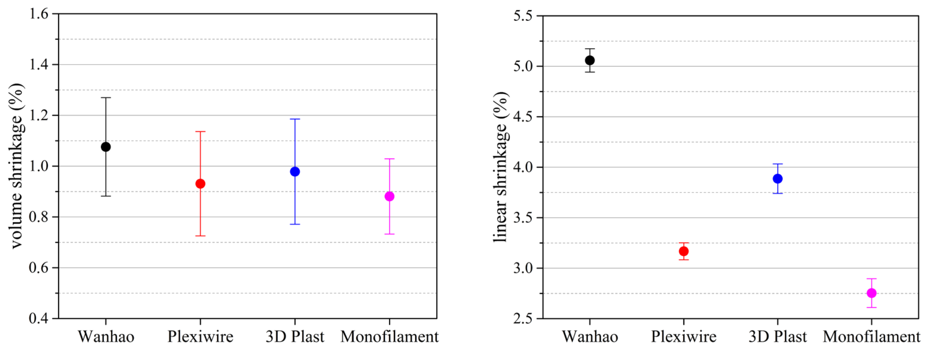
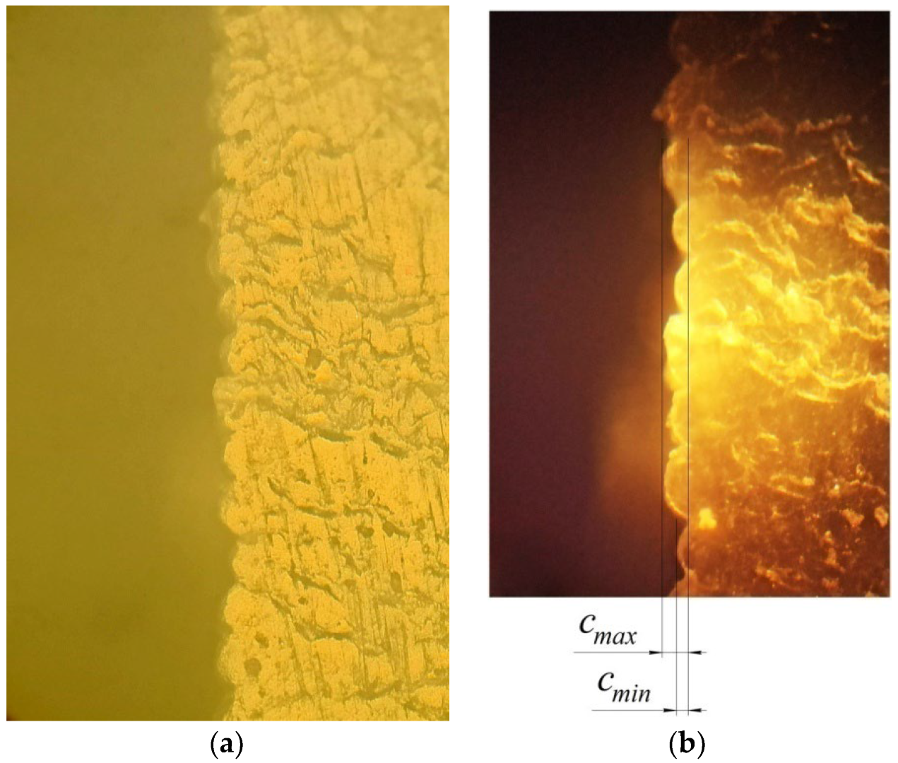
3.3. Coefficient Shrinkage of Material

Many publications have been devoted to the definition of shrinkage of material in 3D printing, namely, in [93,94,95,96] and others. However, in these works, everything comes down to the authors’ proposal of a general shrinkage coefficient for the entire model. However, as previously defined for holes such as nozzles, there are additional factors affecting the reduction in the size of the holes obtained during 3D printing. Therefore, for further shrinkage calculations, both the maximum quality settings of the 3D model and the arc compensation factor were used. As such, all of those factors that affect the reduction in size of the 3D print nozzle were discarded, to obtain a shrinkage value dependent on the print parameters and material parameters. The volume shrinkage value was calculated using the equation:
ε v = V 0 V e n d V 0 100 % ,
where V0 is the initial wall volume of the designed nozzle, and Vend is the final wall volume of the printed nozzle.
The average linear shrinkage of the part was determined by the equation:
ε l = L 0 L e n d L 0 100 % ,
where L0 is the starting linear size of the designed object, and Lend is the ending linear size of the printed object. The shrinkage size of the printed model was determined by the calculation presented in Appendix A.
Experimental research methods are usually used to determine linear shrinkage. To further investigate the effect of shrinkage on the reduction in the size of the print nozzle, we printed nozzles using the elements in Figure 5 and the parameters given in Table 3.
The studies showed that the dend varied within the error range of the measuring instruments by ±0.01 mm, which confirmed the adequacy of the methodology for calculating the arc compensation coefficient, since—depending on the wall thickness and the size of the hole—the error factor of volumetric and linear shrinkage did not exceed 0.5%. From the results given in Table 3, the average volume shrinkage for PLA (Wanhao) plastic was 1.207%, and the average linear shrinkage was 5.058% for PLA (Wanhao) plastic. According to the above method, volumetric and linear shrinkages for PLA filaments of manufacturers were experimentally determined for Wanhao [90], Plexiwire [97], 3D Plast [98], and MonoFilament [99] (Figure 13).
As shown in Figure 13, volume shrinkage for almost all filament manufacturers was close to 1%, and ranged ±0.2%. However, linear shrinkage, for which model sizing is carried out during 3D printing, had a large deviation for the various filament manufacturers, reaching up to 3%. Large shrinkage in 3D Plast and Wanhao samples may have been due to the use of non-high-quality raw materials, or process disruption. However, the linear shrinkage of filaments may have been due to variations between batches of the same manufacturer. Therefore, in order to ensure the most accurate 3D printing, it was necessary to determine the linear shrinkage factor for each batch and calculate the shrinkage compensation factor of the diameter of the printing hole:
k s h r = d 100 100 ε l 1
.
For the above PLA filaments of various manufacturers, the diameter of the 3D nozzle model was calculated to provide the nominal diameter of the print nozzle of the gripping devices according to the equation:
d = d n + k S T L + k A r c + k s h r
.
For a nozzle with a diameter of 6 mm, wall thickness of 1.6 mm, using Wanhao filament, and with the maximum quality of a 3D model, the diameter of the 3D nozzle model was d = 6.325 mm, which was the largest for all filaments for which the experiment was conducted. For the calculated nozzle diameter, gripping devices were printed at different printing heights, from 0.05 to 0.2 mm, in increments of 0.05 mm. The diameter of the 3D printed nozzle was 6 ± 0.01 mm, which lay within the accuracy of the measuring instruments. The obtained results of the study make it possible to assert the adequacy of the proposed model for calculating the diameter of holes of small diameters using FDM 3D printing. Using the proposed model, Bernoulli grippers with nozzles less than 8 mm in diameter can be printed with a maximum accuracy of the printing hole diameter.

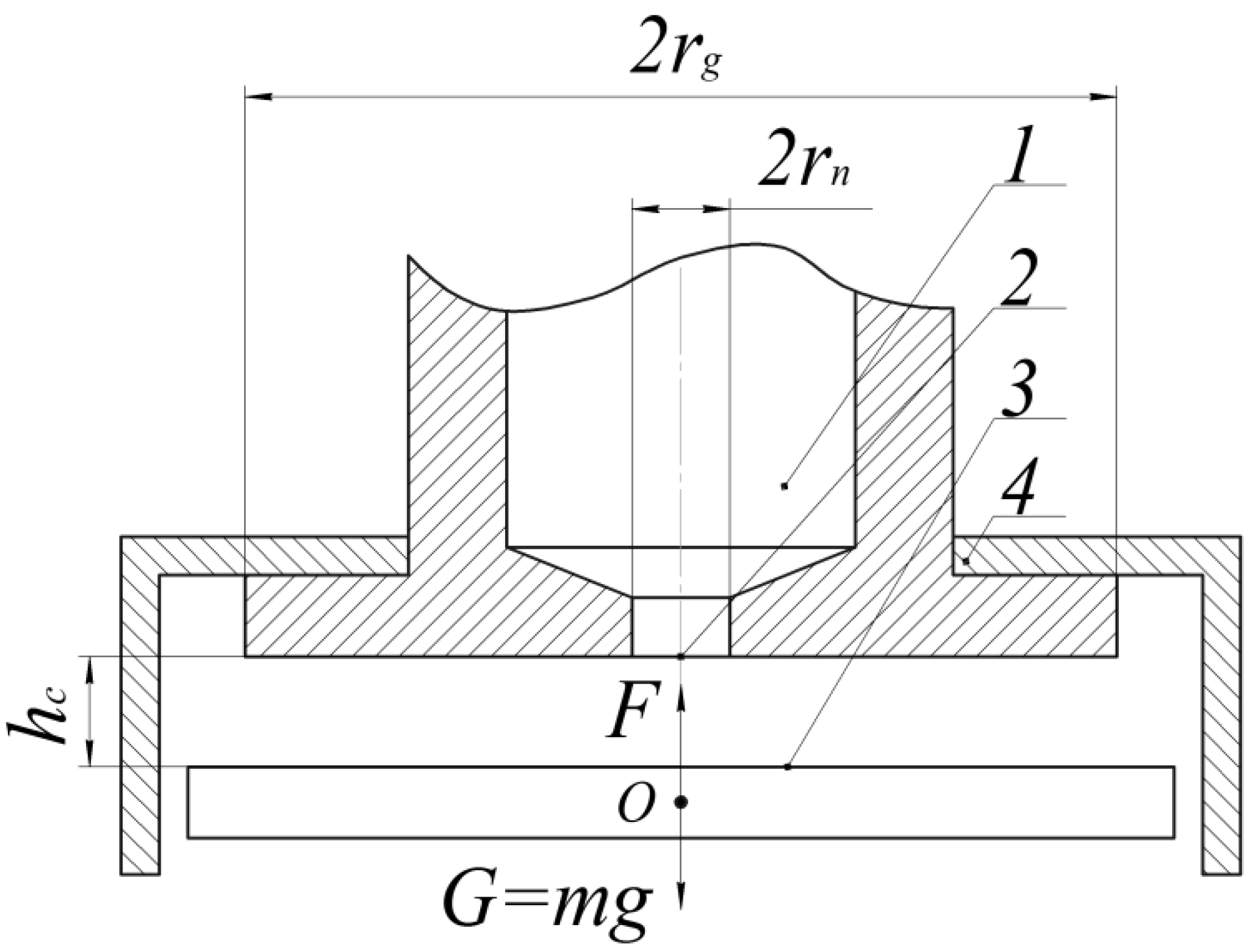
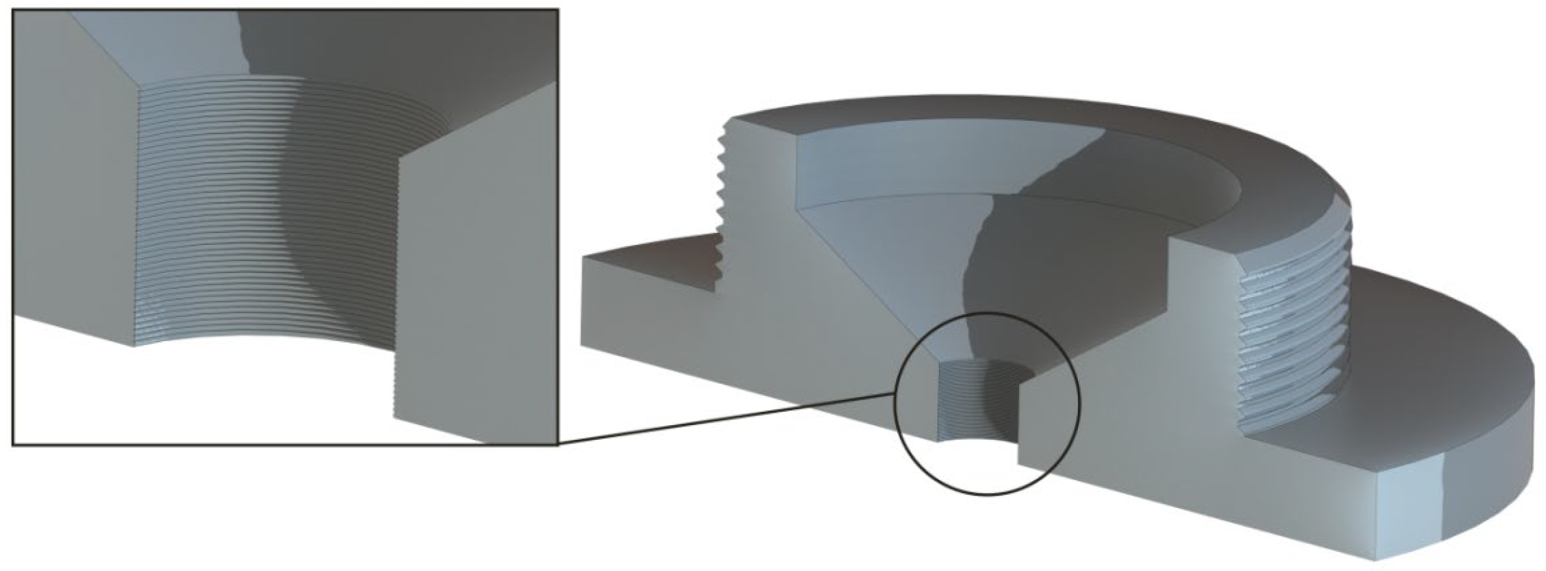
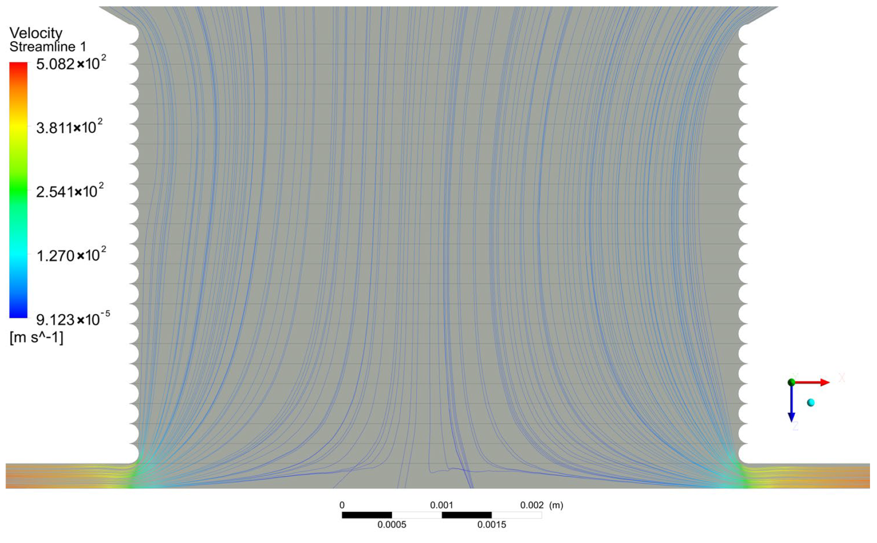
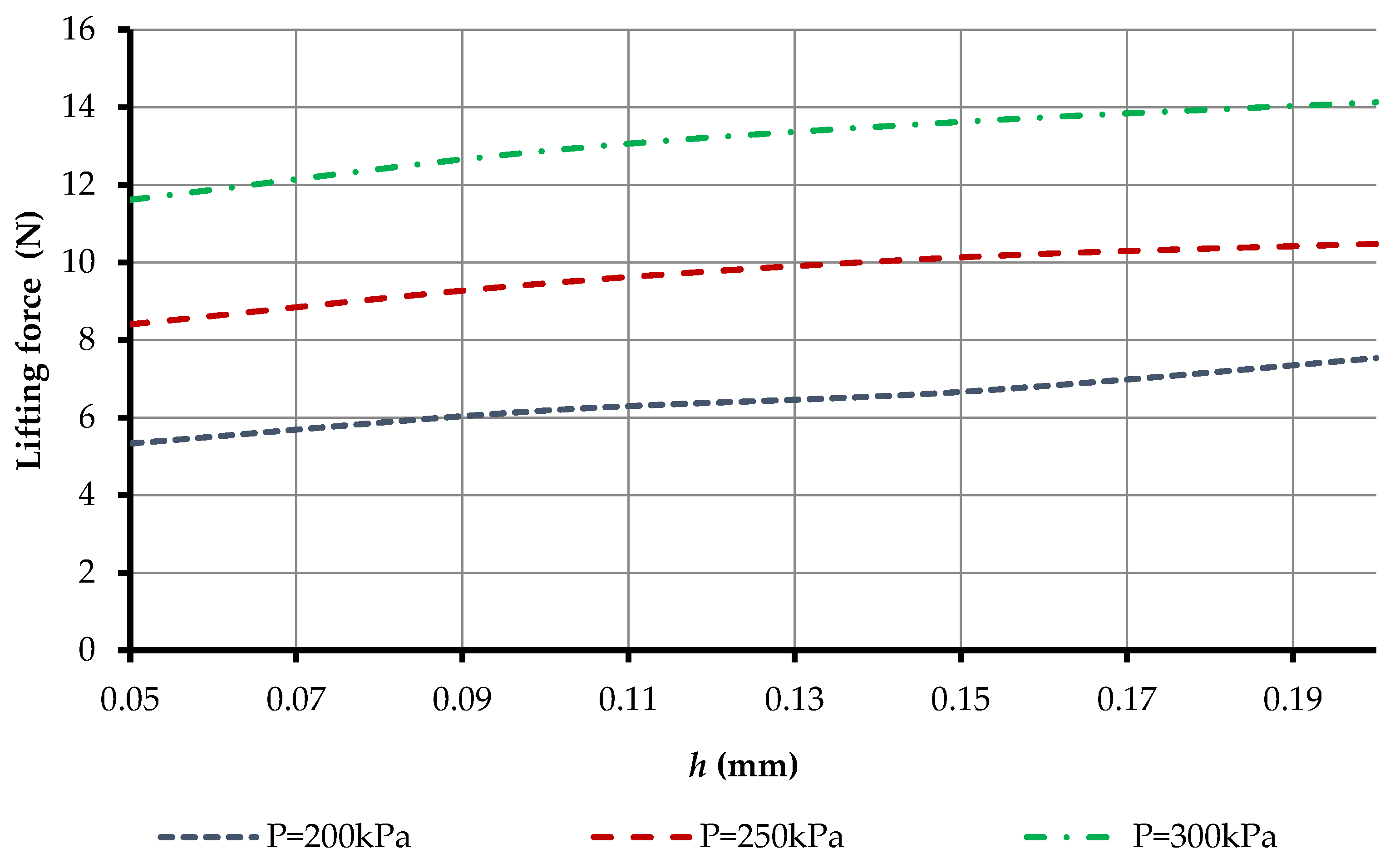
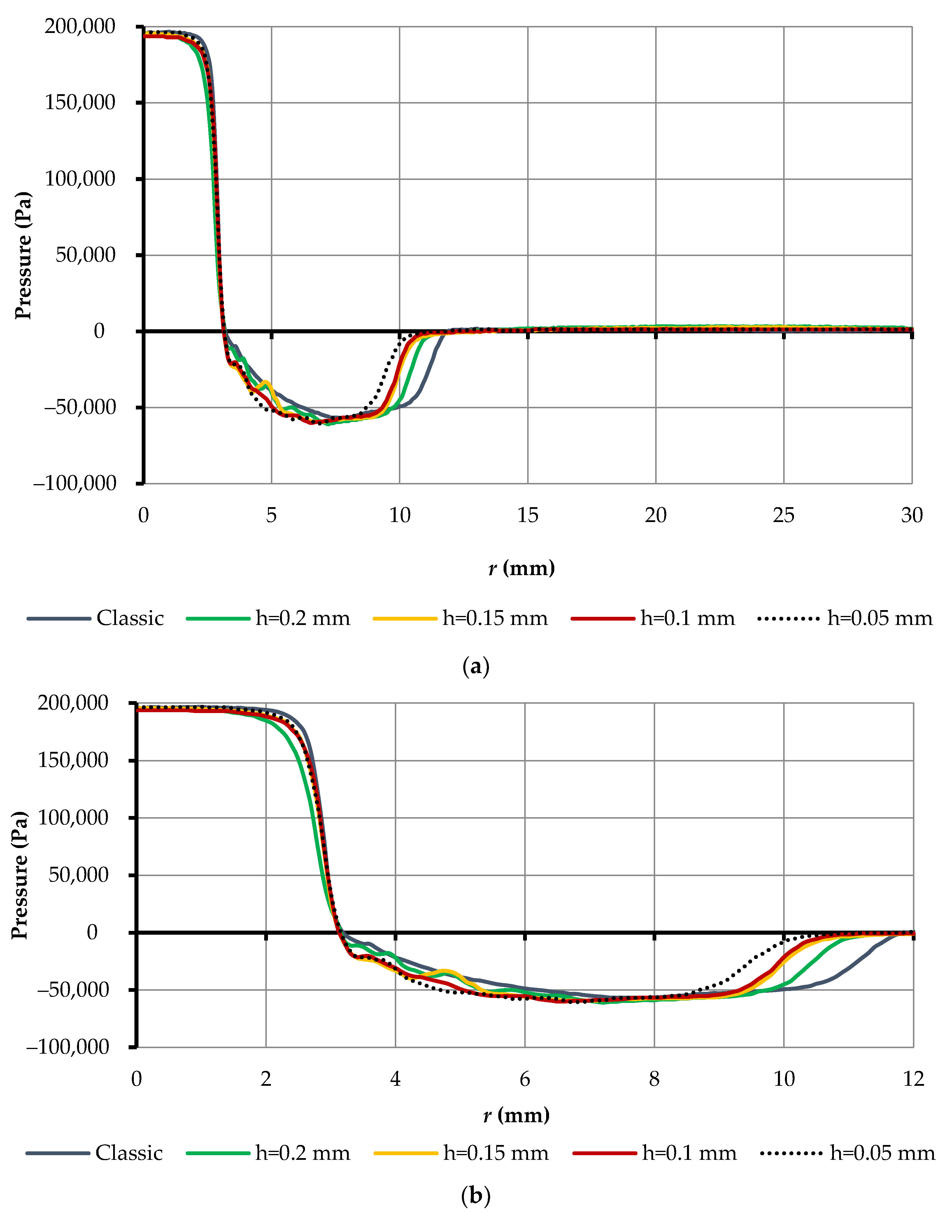
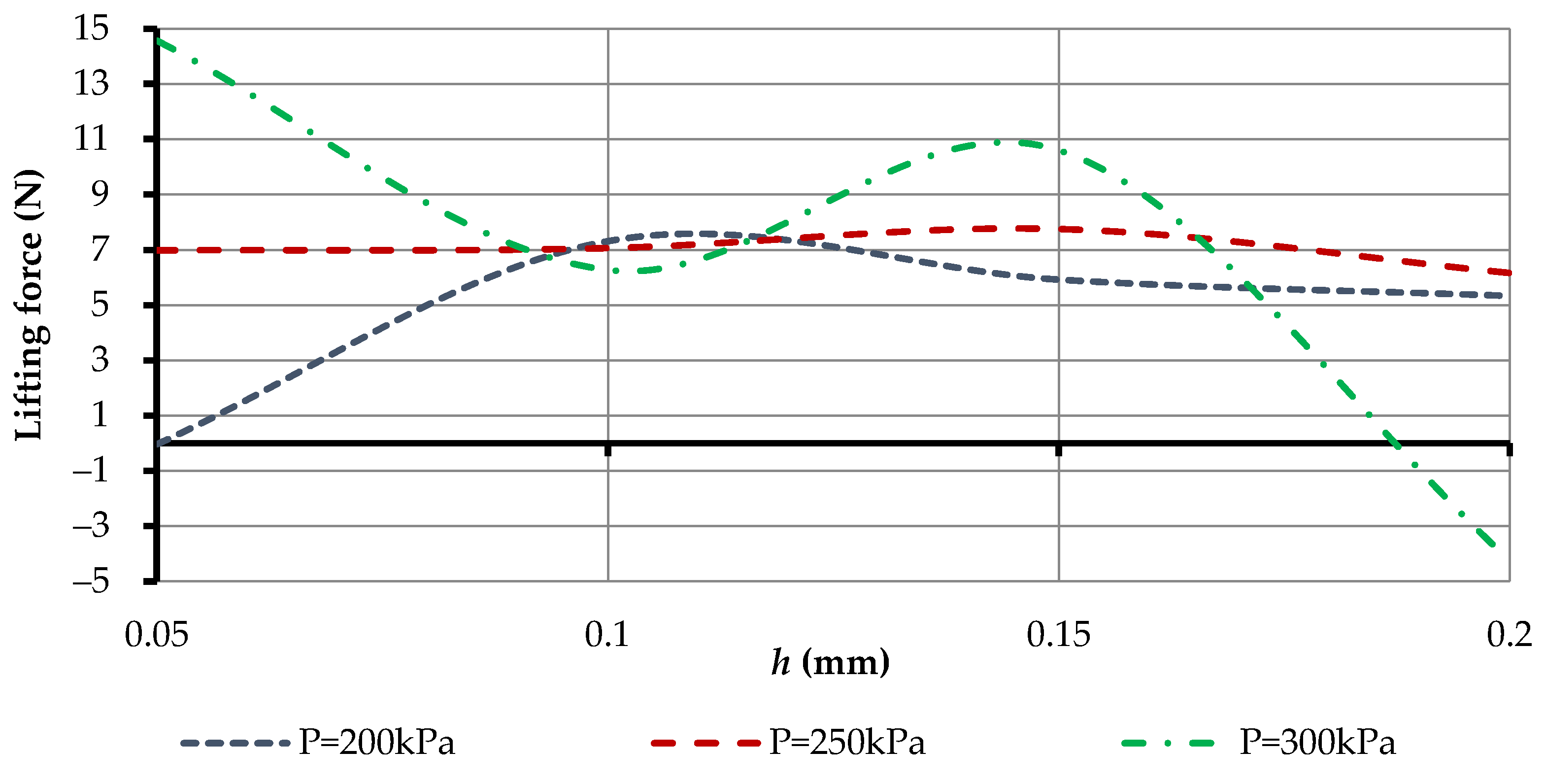
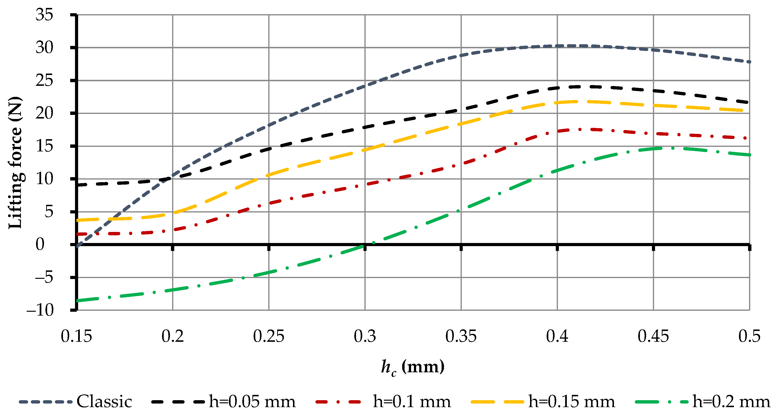
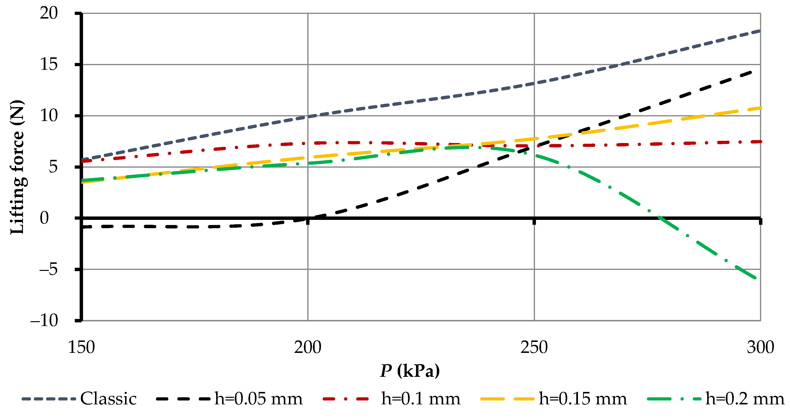
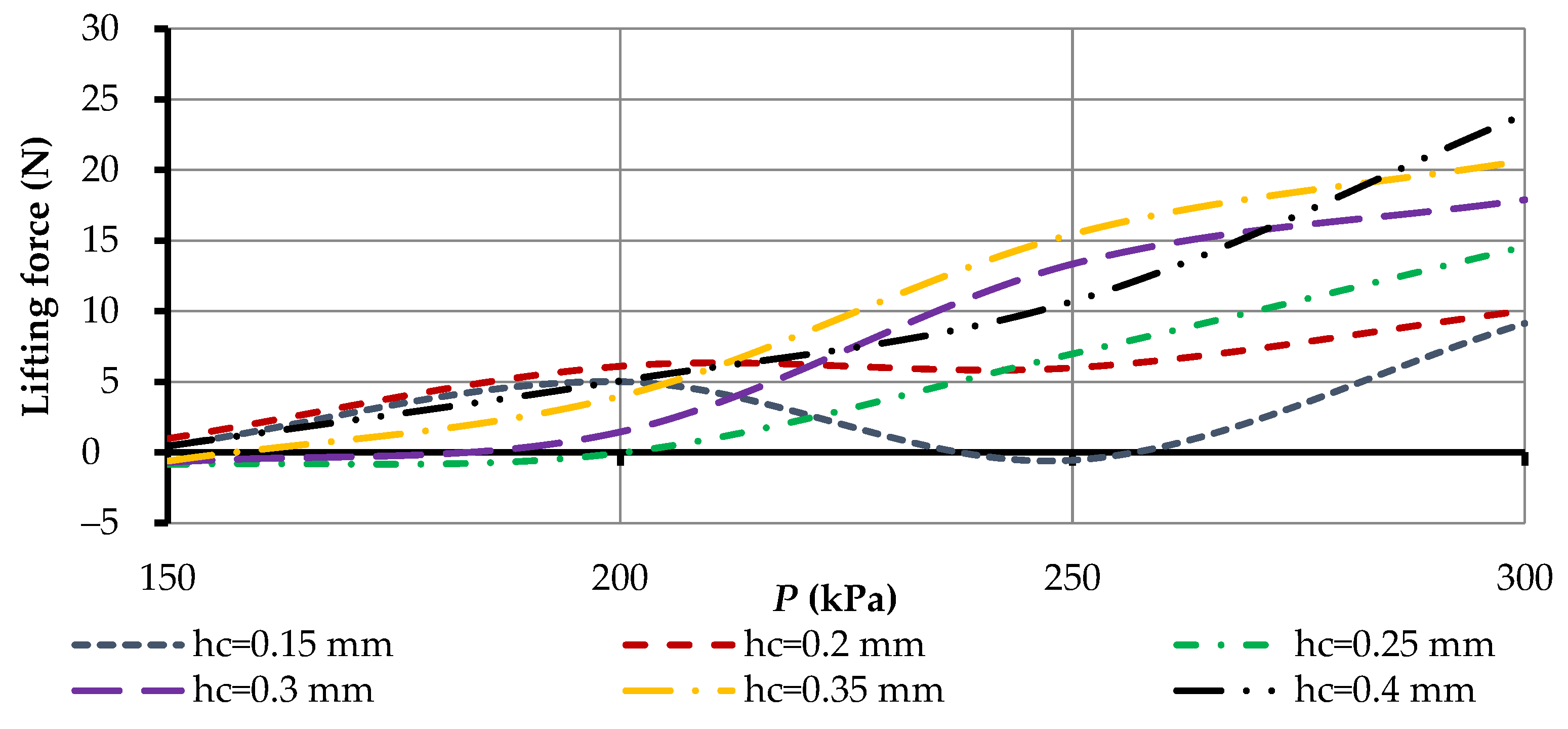
3.4. Effect of 3D Printer Surface Geometry on Power Characteristics of Gripping Devices

Bernoulli grippers use compressed air to provide lifting force, and their operation has been described above (Figure 2). Based on the design of the gripping devices, when the nozzle elements are 3D printed, the nozzle geometry will have the greatest influence on the power characteristics of the printed gripping device, which will not be smooth, since it is formed by a build-up of plastic with a certain layer height. Even compared with the classic production of Bernoulli grippers, 3D printing, delightfully, will ensure a greater roughness of the end surface of the grip. To determine the effect of the geometry of the nozzle surface on the power characteristics, nozzle elements were printed with their subsequent splitting along the nozzle axis. This made it possible to survey the section of nozzle elements on a microscope at 100 times magnification (Figure 14).
It can be seen from Figure 14 that there was some deviation in the surface geometry that formed the nozzle wall. To determine the average value of performances of each of the layers, the following equation was used:
c mid = c max + c min 2
.
Most often, for FDM 3D printing, the diameter of the extruder nozzle is 0.4 mm. When printing with a 0.4 mm nozzle, to ensure optimal printing parameters, a range of printing layer heights would be selected, from 0.05 to 0.2 mm. Therefore, our next studies were carried out for this range of printing layer heights, and the average value of the performance of the layers was examined (Table 4).
As can be seen from the experimental studies in Table 4, the average performance of the layers during 3D printing was half the height of the printing layer. Using the data on the geometry of the shape of the nozzle element of the gripping devices during printing, it was possible to conduct 3D modeling of the gripping devices for further investigation (Figure 15).

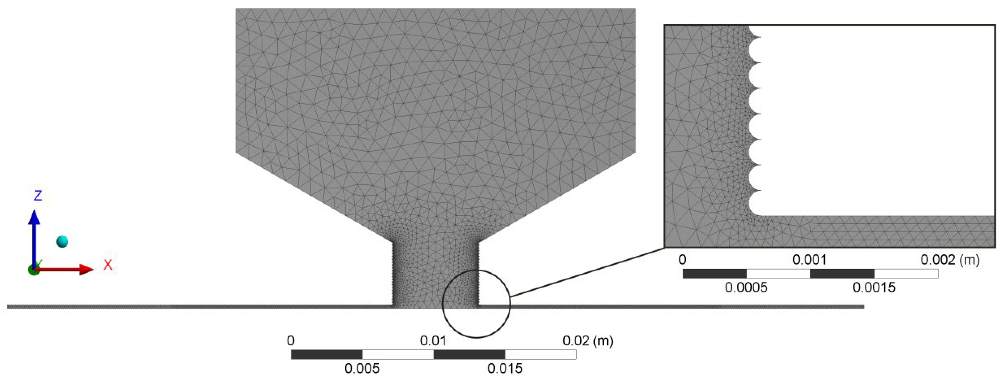
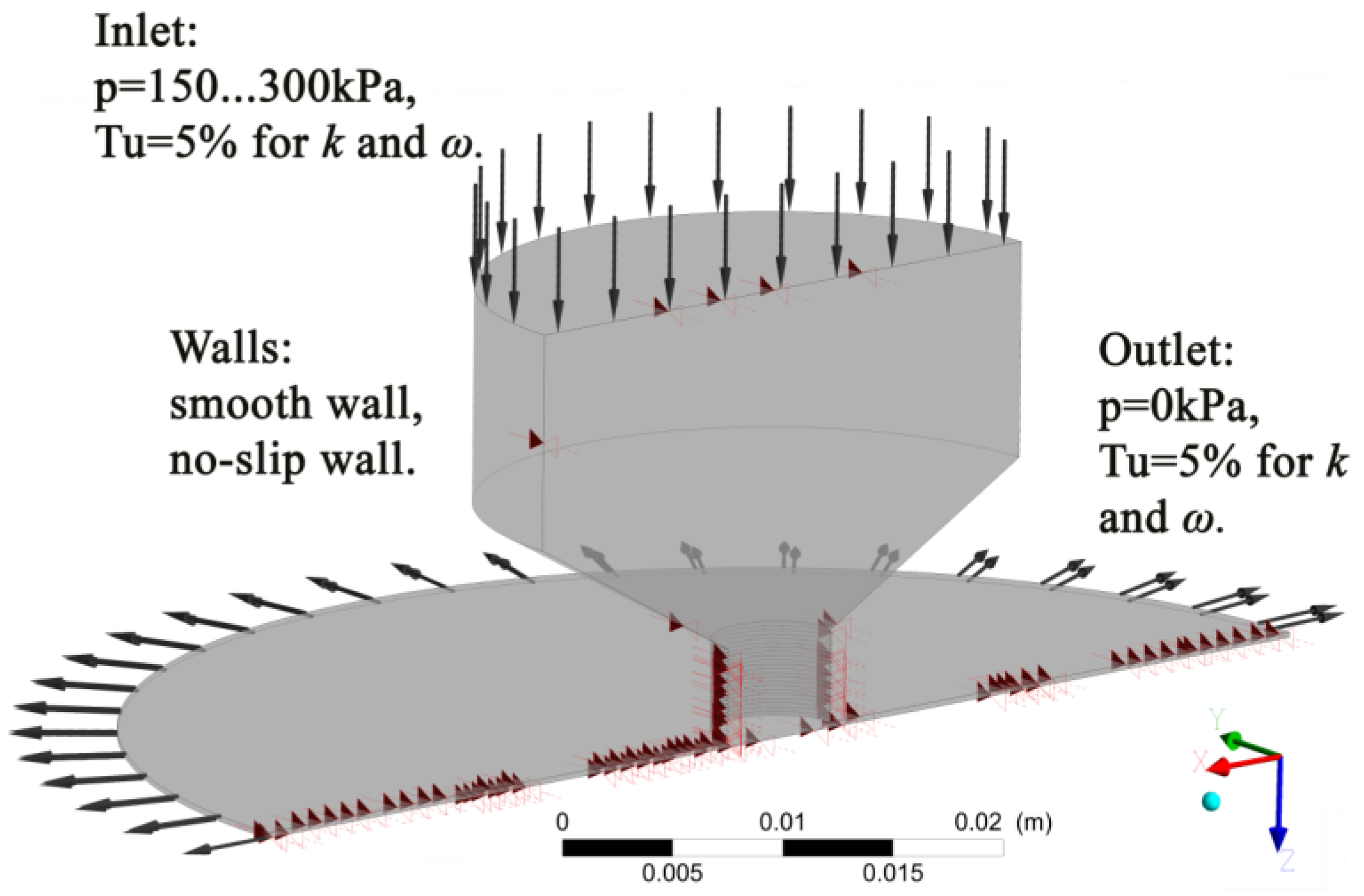
3.5. Description of the Finite Element Method for BGD Research

The mathematical model of air in the radial interval between the interacting surfaces of a BGD and an OM was based on the Navier–Stokes’s equation average according to Reynolds (Reynolds-averaged Navier–Stokes equations) (RANS) [100,101]. The SST-model of turbulence [102] and the gamma-model of laminar and turbulent transition [103] were used for modeling. The main equations for describing these models are presented in Appendix B.
Numerical modeling was carried out in the environment of computing hydro-gas dynamics by Ansys-CFX with the use of the SST gamma-model of turbulence. For carrying out calculations, the program environments in the settlement area were constructed with an unstructured differential grid (Figure 16).
The total number of nodes in the calculation area depended on the outer radius of the gripper r1 and the height of the gap between the object of manipulation and the gripper hc. To ensure adequate operation of the SST model, to model the wall air flows, it was necessary that the minimum number of elements between the walls of the model was three elements. Therefore, the number of nodes was in the range of 0.9–3 million, and the number of elements was 4.5–12 million, and for the range of distances between BGD and OM hc = 0.1…0.4 mm. Ideal gas from the program library was used during the simulation. Boundary conditions for model of air flow are presented in Figure 17.
Using the sonicTurbFoam solver (for turbulent streams of the compressed gases moving with sound and supersonic speeds), the value of the distribution of teak, speed, and force over the surfaces of the studied model, was obtained.

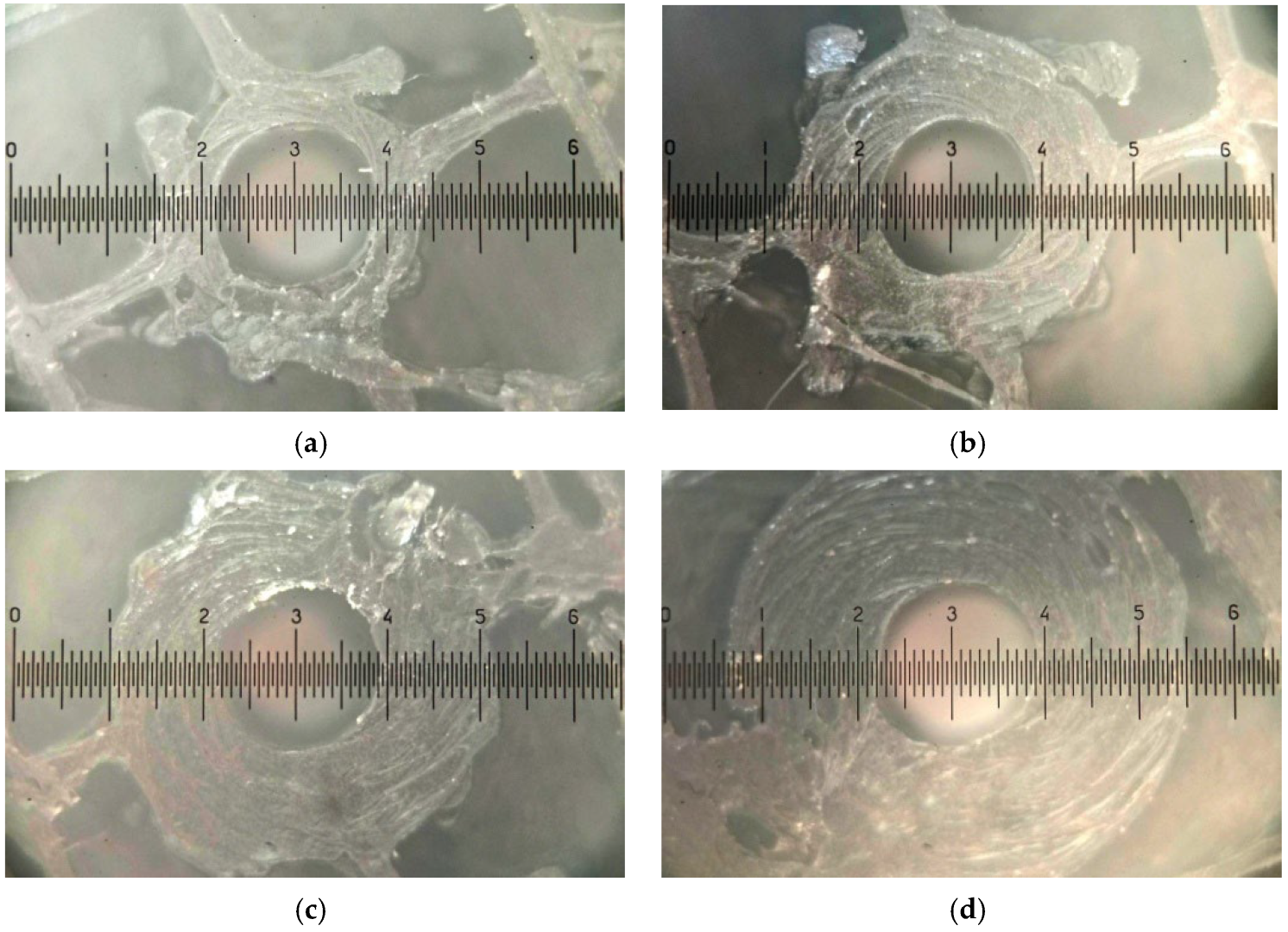
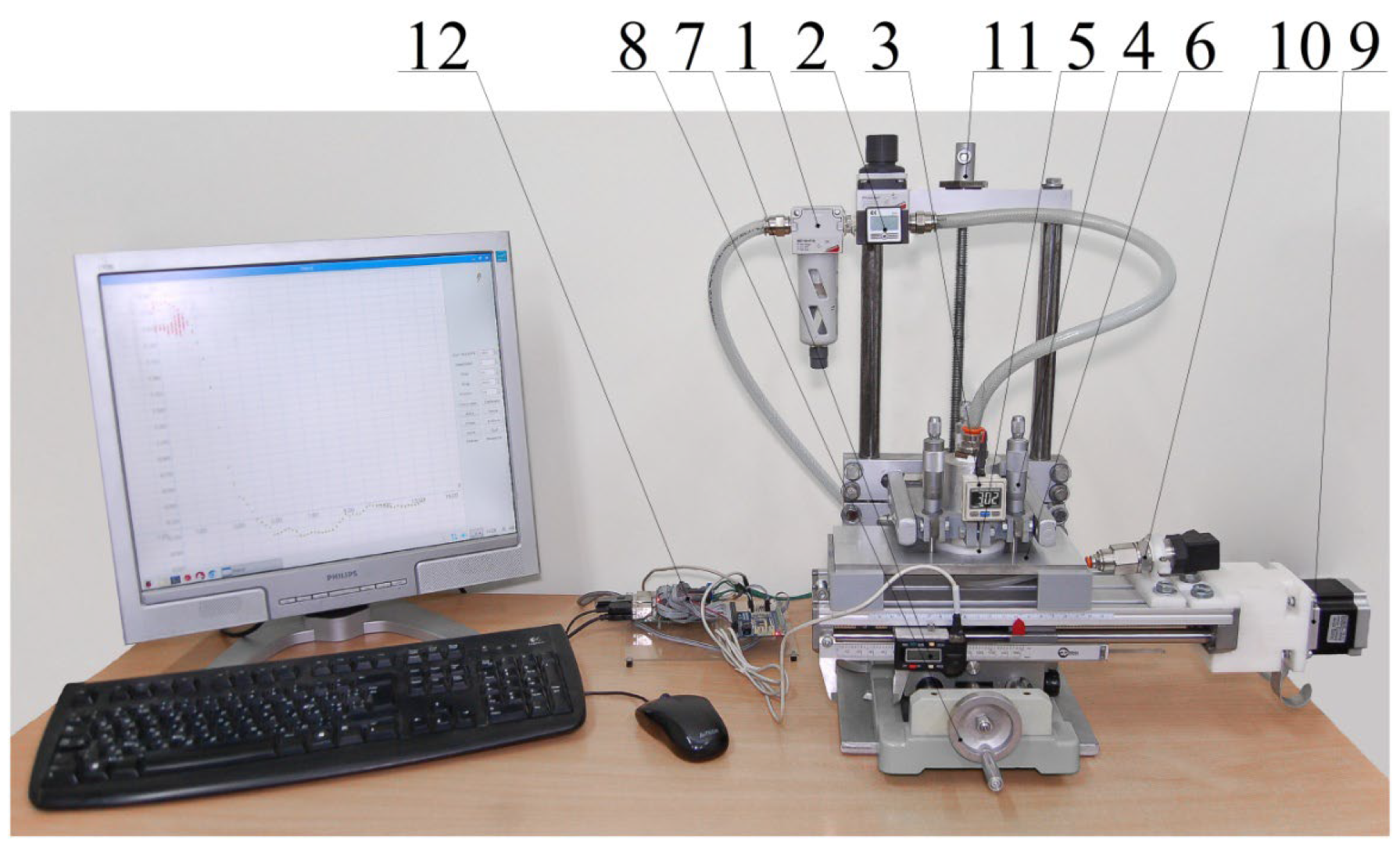
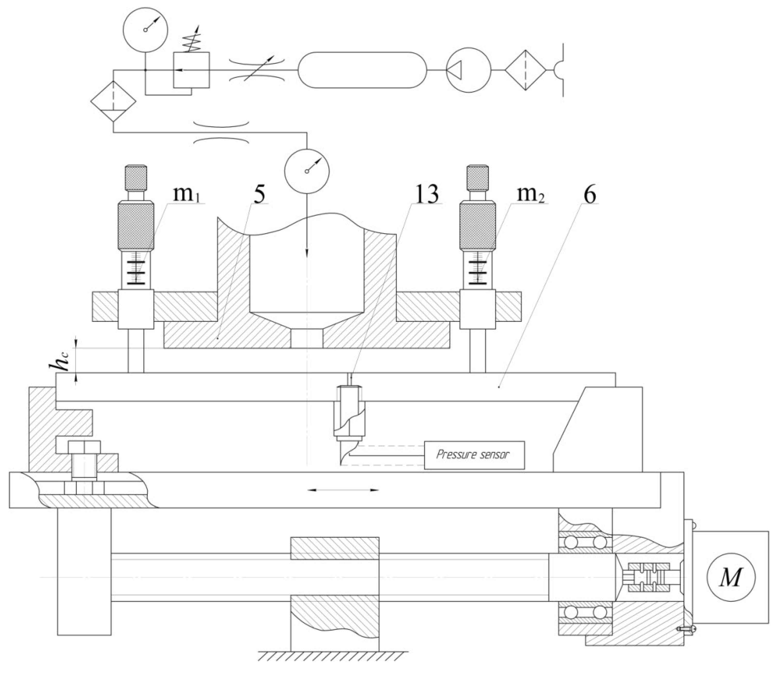
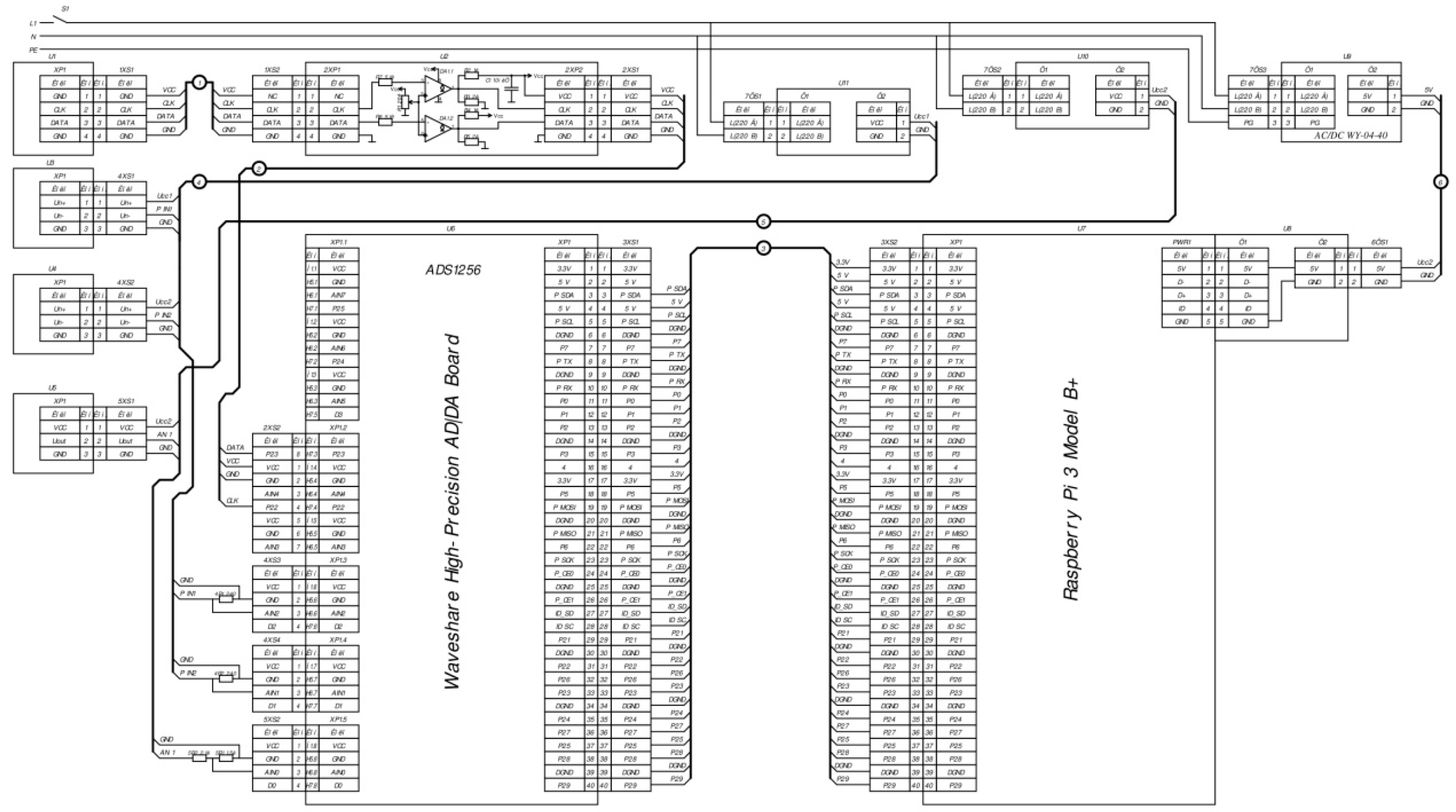
3.6. Methods of Experimental Research

To obtain experimental results of the pressure distribution on the surface of the object of manipulation during gripping with the help of Bernoulli gripping devices with nozzle elements of different parameters, an experimental setup was developed (Figure 18).
The scheme of work of the experimental installation is shown in Figure 19. The experimental setup (Figure 18) consisted of: 1—air preparation device, 2—precision reducer for regulating the pressure in the gripper chamber, 3—pressure sensor in the gripper device chamber, 4—three micrometer heads (m1, m2, m3), which set the height of the gap hc between the surfaces of the gripping device—5 and the object of manipulation—6, 7—motion sensor (electronic caliper) on the x-axis, 8—y-axis movement device, 9—stepper motor for movement on the x-coordinate, 10—pressure sensor, which was connected to a measuring nozzle with a diameter of 0.3 mm in the center of the manipulation object–6, 11—a device for moving along the z axis, and 12—a controller built on the board Raspberry Pi 3B, and other peripherals for work with the installation.
The scheme shows a pneumatic diagram of the supply of compressed air to the chamber of the Bernoulli gripping device—1. After supplying compressed air to the chamber of the gripper—5 on the surface of the object of manipulation—6, zones of excess and negative pressure were formed and the object of manipulation was attracted to micrometers m1, m2 and m3. This provided a pre-set with a micrometer (m1, m2 and m3) gap between the GD and the OM. After gripping the object of manipulation—6, the pressure distribution along the x-axis was measured using a measuring nozzle—13, which moved the OM relative to the GD by means of a mechanical transmission screw-nut, which was driven by a stepper motor. The system and the measurement process were controlled by a single-board Raspberry Pi 3B microcomputer. The schematic diagram and the process of signal processing are described in Appendix C.

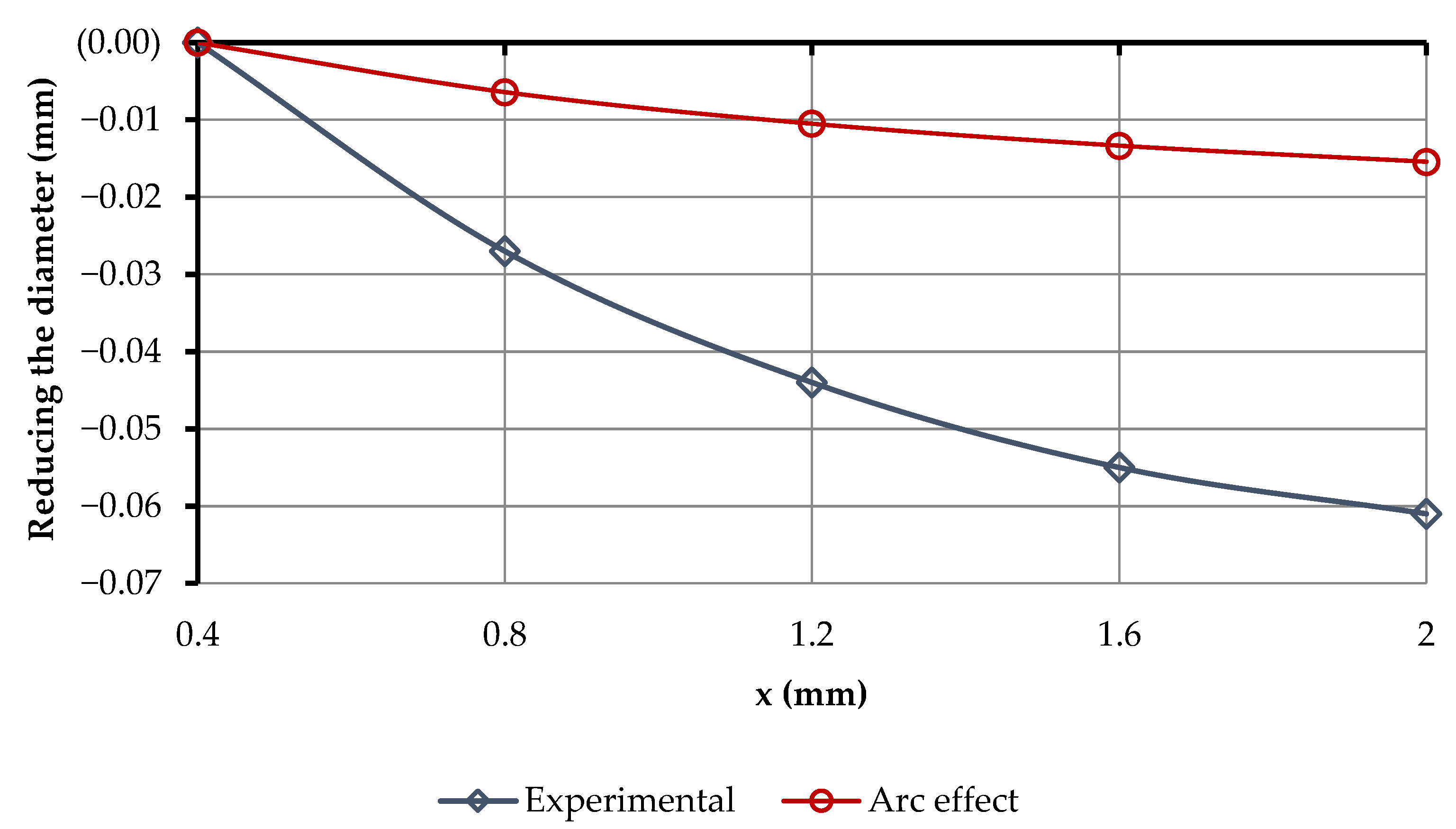
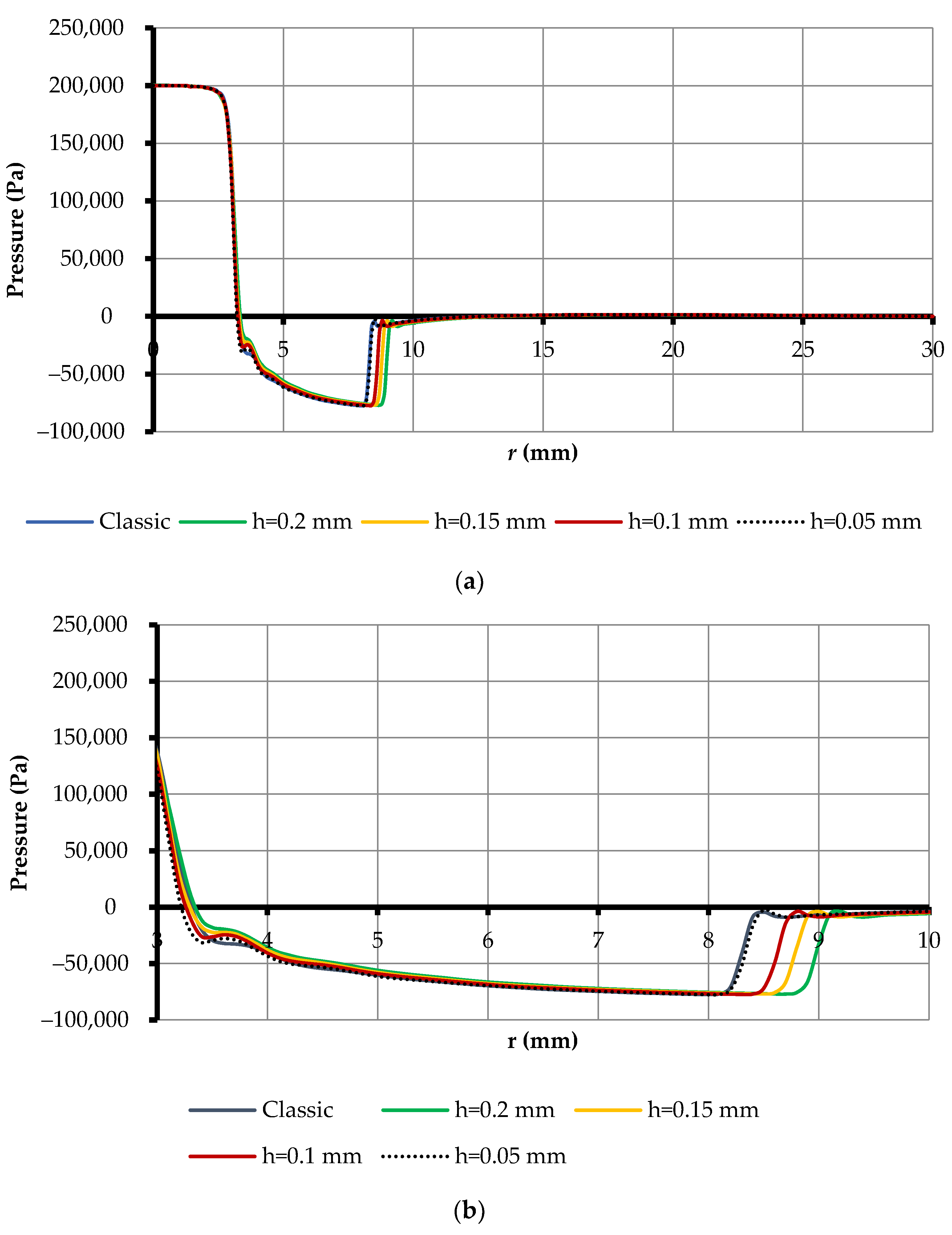
3.7. Results of the Influence of 3D Printing on BGD

To determine the effect of the height of the gripper print layer on its power characteristics, the manipulation object gripping process was simulated in the Ansys-CFX software environment using the finite element method presented above. In particular, an arc compensation algorithm was used to obtain a nozzle with a diameter of 6 mm during 3D printing and the use of Wanhao plastic. At the same time, the height of the printing layer changed from 0.05 mm to 0.2 mm with a pitch of 0.05 mm, which made it possible to determine the distribution of pressure on the surface of the object of manipulation (Figure 20).
As can be seen from the results of the simulation shown in Figure 20, grips with different layer heights during 3D printing had different rarefaction zones. In all other zones, the pressure distribution was almost equal for all gripping devices with different 3D printing layer heights, which led to different lifting forces. As can be seen from Figure 20, the vacuum zone increased as the height of the layer increased. This was due to the fact that, compared with the classic gripper in FDM-printed grippers, the edge of the nozzle was a rounded edge (Figure 21).
It can be seen from Figure 21 that the rounded edge of the air flowed smoothly around the narrowing zone of the flow, thereby preserving the kinetic energy of the air flow. Having a large kinetic energy, the air flow created a wide vacuum zone, thereby, increasing the lifting force of the Bernoulli gripping devices (Figure 22). However, the height of the print layer cannot be thoughtlessly increased—this may result in poor sintering of the layers, so it is recommended that the height of the layer does not exceed 50% of the diameter of the extruder nozzle. In our case, when printing with a 0.4 mm nozzle, the height of the printing layer did not exceed 0.2 mm.
Obviously, from Figure 22, the lifting force increased as the height of the printing layer increased at different feed pressures, which was a great advantage. However, since this was only a process simulation, it did not take into account the many processes that occur when gripping manipulation objects, such as the error of the hole geometry, the roughness of the active surface of the gripping devices, and the properties of the gripping material and the manipulation object. Since all these properties cannot be taken into account in the simulation, an experimental study was carried out on the effect of layer height in 3D printing. For this, according to the above experimental research method, the distribution of air over the surface of the object manipulation was formed by the Bernoulli gripping device (Figure 23).
As can be seen from Figure 23, by rounding the edge of the nozzle as a result of 3D printing, the pressure in the area opposite the nozzle decreased as the height of the nozzle h increased. Deflection of nozzle roundness and surface roughness critically affected the size of the vacuum zone. In FDM 3D printing, surface roughness of the invaders in the rarefaction zone produced swirls, causing pressure surges and a reduction in the length of the rarefaction zone. For further analysis of the experiment, the lifting forces of the Bernoulli grippers were determined (Figure 24) by integrating the pressure distribution on the surface of the OM:
F = 2 π 0 r g p a p r d r .
As can be seen from Figure 24, the maximum lifting force was achieved by using gripping devices printed at the layer height of h = 0.05 mm. This was due to the fact that at this layer height, the minimum roughness of the active grip surface was provided and the effect of rounding the printed nozzle was present. Additionally, at inlet pressure 300 kPa, the greatest deviations of lifting force were observed, as a bigger pressure of turbulence critically influenced the lifting force. However, depending on the height of the gap hc between the manipulation object and the Bernoulli grips, swirls through the surface roughness will possibly form. Therefore, the effect of the gap height hc between the OM and the BGD, on the lifting force at constant supply pressure p = 300 kPa, was investigated (Figure 25).
Figure 25 shows a clear relationship between the height of the gap hc between the Bernoulli grips and the object of manipulation on the power characteristics of the gripper. In particular, in all samples of grippers, the maximum lifting force was achieved at a height of hc = 0.4 mm. The best values of the lifting force were observed in all areas of the gap height hc of gripping devices with a printing height of 0.05 mm. In addition, the supply pressure of the Bernoulli grippers on the lifting force at different heights was important in 3D printing the gripper (Figure 26).
As seen in Figure 26, the most linear force characteristic had a gripper that was printed at a layer height of h = 0.15 mm. However, the highest lifting force compared with the classic aluminum grip was a BGD which was printed at a layer height of h = 0.05 mm. For a BGD printed at a layer height of h = 0.2 mm, the lifting force decreased at 300 kPa pressure, which was caused by the formation of local turbulence zones through the surface roughness of the gripping devices. For further analysis, the BGD of a printed layer height of h = 0.05 mm was considered, which showed the highest power characteristics compared with other 3D printers. An experimental study of the effect of BGD input pressure (h = 0.05 mm) on its power characteristics at different contact heights between OM and GD was undertaken (Figure 27).
Figure 27 shows that as the supply pressure increased, the lifting force increased. In particular, low power characteristics were noted at a gap of 0.15 mm to 0.25 mm, due to the increased effect of the roughness of the active surface of the Bernoulli gripping devices on its lifting force. In addition, focus should be placed on the operating range of the supply pressure. For this Bernoulli gripping device with a layer height of 0.05 mm, the operating range started from 200 kPa. From the point of view of operation of the gripping device, it was obviously necessary to provide the most linear dependence of the supply pressure and the lifting force. The most linear, and providing the maximum lifting force, was a working gap between the OM and GD, from 0.3 mm to 0.4 mm. Therefore, if low contact with the object manipulation is necessary, it is necessary to choose friction elements with a height of 0.3…0.4 mm to ensure the maximum lifting force.

4. Conclusions

The article presents a comprehensive study of the prototype of Bernoulli gripping devices with a cylindrical nozzle, manufactured by FDM 3D printing. In order to ensure an appropriate nozzle diameter of the Bernoulli gripping devices when 3D printing, a methodology was developed to determine the diameter of the CAD model so that after printing the gripping devices, the diameter of the nozzle was planned. The three main reasons for reducing the diameter of the gripping device nozzle after 3D printing were identified as being due to poor 3D STL model quality, excessive extrusion of plastic in the middle of the arc printing path, and linear shrinkage of filament material after object cooling. The proposed methodology consisted of determining the three coefficients that allowed the determination of the diameter of the designed nozzle.
It was determined that excessive extrusion of plastic in the middle of the arc printing path only affected the nozzle diameter when the diameter was less than 8 mm. Given the arc compensation coefficient, it was possible to determine the linear and volume shrinkage of several PLA filaments of various companies with an accuracy range of ±0.2%. According to the offered methodology of compensation of diameter of a nozzle, 3D printing of a Bernoulli gripping device with a cylindrical nozzle was carried out with a diameter of 6 mm and by changing the printing layer height from 0.05 to 0.2 mm. It was proved that the height of the printing layer did not affect the diameter of the cylindrical nozzle manufactured by FDM 3D printing, and the diameter error was ±0.02 mm.
Proposed methodology and an installation for experimental studies of air pressure distribution over the surface of the object manipulation were constructed. It was determined that as the height of the printing layer increased, the lifting force decreased due to the swirls formed through the surface roughness of the manipulation object. It was proved that as the height between the object of manipulation and the gripper increased, the effect of surface roughness on the lifting force decreased, which led to its increase. It was found that the maximum lifting force was provided when printing the grip with a layer height of 0.05 mm, and a height of 0.4 mm between the object of manipulation and the grip. The complex power characteristics of the gripper were determined with a printing layer height of 0.05 mm, at the change of supply pressure from 150 to 300 kPa, and a change of height between the object of manipulation and the grip from 0.15 to 0.4 mm. It was established that the operating range of the feed pressure for a gripper with a printing layer height of 0.05 mm started from 200 kPa, and the rational height of the friction elements at low contact with the object of manipulation was from 0.3 to 0.4 mm.
This study has certain limitations in relation to the assumptions. One limitation concerns the orientation of the nozzle during 3D printing, which in this study was required to be oriented perpendicular to the table. The second limitation concerns the design of the 3D printer, namely, a closed-type printer was used to ensure a constant temperature and uniform shrinkage of the part. In the future, it is planned to conduct 3D printing and research of gripping devices using nozzle elements of various geometric shapes and printing in different orientations. Such a study will simplify the technology of manufacturing gripping devices and ensure their maximum power characteristics using additive technologies. Therefore, this article serves as a basis for introducing and manufacturing more complex geometry of nozzle elements and holes using FDM and SLA 3D printing.

Author Contributions

Conceptualization, R.M. and A.M.F.; methodology, R.M. and M.M.; software, R.M.; formal analysis, R.M., M.M. and F.D.; investigation, R.M.; resources, A.M.F.; writing—original draft preparation, R.M.; writing—review and editing, R.M., F.D. and A.M.F.; visualization, R.M.; project administration, A.M.F.; funding acquisition, R.M and F.D. All authors have read and agreed to the published version of the manuscript.

Funding

This work was supported in part by the U.S. Department of State (DOS), Bureau of Educational and Cultural Affairs (ECA), Exchange Visitor Program #G-1-00005 under Fulbright Grant PS00322778; by the projects DIH2 ID: 824964 and Better Factory ID: 951813.

Institutional Review Board Statement

Not applicable.

Informed Consent Statement

Not applicable.

Data Availability Statement

Not applicable.

Acknowledgments

Roman Mykhailyshyn would like to thank Ann Majewicz Fey for the opportunity to conduct research in her laboratory.

Conflicts of Interest

The authors declare no conflict of interest.

Appendix A

The shrinkage size of the printed model was determined by calculation, using the following equations.
For linear shrinkage:
ε l = α l t 0 t e n d ,
For volume shrinkage:
ε v = α v t 0 t e n d ,
where αl represents the coefficients of thermal compression at linear shrinkage; αv represents the coefficients of thermal compression at volume shrinkage, which are due to the physical properties of the body; t0 is the temperature of the beginning of linear shrinkage; and tend is the final temperature equal to the ambient temperature.
For pure plastics, the start temperature of linear shrinkage coincides with the crystallization temperature. For alloys (composites) that crystallize in the temperature range, the beginning of linear shrinkage corresponds to the formation of a solid skeleton of crystals and can be approximately determined by the equation:
t 0 = t l + t s 2 ,
where tl is the liquidus temperature above which the alloy is completely in the liquid state, and ts is the solidus temperature below which the alloy is in the solid phase.

Appendix B

The gamma model of laminar and turbulent transition is described by one differential equation for intermittency coefficient γ:
( ρ γ ) t + ( ρ V j γ ) x j = P γ E γ + x j μ + μ t σ γ γ x j ,
where ρ —the air density; t—the time; x—the coordinate; V—the vector of air velocity; P γ , E γ —the generative and dissipation members of managing directors of laminar and turbulent transition, respectively; μ—the molecular dynamic viscosity of gas; μ t —the turbulent dynamic viscosity of gas; and σ γ = 1.0 —the model constant.
The coupling between the transition model and the SST turbulence model was the same as for the γ-Reθ model [104] and was accomplished by modifying the equations of the original SST model as follows:
t ( ρ k ) + x j ( ρ V j k ) = P ˜ k + P k lim D ˜ k + x j ( μ + σ k μ t ) k x j ,
t ( ρ ω ) + x j ( ρ V j ω ) = α P k v t D ω + C d ω + x j ( μ + σ ω μ t ) ω x j ,
P ˜ k = γ P k ,
D ˜ k = max ( γ , 0.1 ) D k ,
μ t = p a 1 k max ( a 1 ω , F 2 S ) ,
S i j = 1 2 V i x j + V j x i ;   S 2 = 2 S i j S i j ,
where k—the kinetic turbulent energy; ω—the specific speed of dissipation of kinetic energy of turbulence; P k , D k —the original generation and dissipation of the SST model, respectively; P k lim —the additional part, which provides the correct gain of turbulent viscosity in transitional area at a very low level of turbulent viscosity of the running stream; ν t —the turbulent kinematic viscosity of gas; and σ k , α , a 1 —the empirical constants of the model.
The generative member in the Equation (A4) appears as:
P γ = F l e n g t h ρ S γ ( 1 γ ) F o n s e t ,
where Flength is the empirical correlation which controls the length of the transitional area (accept Flength = 100), and Fonset is the function controlling the provision of the beginning of transition.
The destruction/relaminarization source was identical to the one used in the γ-Reθ model [105] and was defined as follows:
S i j = 1 2 V i x j + V j x i ;   S 2 = 2 S i j S i j ,
where ca2 = 0.06, ce2 = 50—the empirical constants; Ω = 2 Ω i , j Ω i , j —the invariant of the tensor of vorticity; F t u r b = e R T 2 4 ; and R T = ρ k μ ω .
The formulation of the function Fonset was similar to that used in the γ-Reθ model. It was used to start the intermittency production (i.e., activate source term (A11)). It contains the ratio of the Reynolds number to the local vortex ReV (in the current formulation, the strain rate was actually used within ReV, which was equivalent to the boundary layers), to the critical Reynolds number Reθc. However, Reθc was not calculated from the transport equation but algebraically, using k and other local variables. As a result, the beginning of the transition was controlled by the following functions:
F o n s e t 1 = Re v 2.2 Re θ c , Re v = ρ d ω 2 S μ ;
F o n s e t 2 = min ( F o n s e t 1 , 2.0 ) ;
F o n s e t 3 = max 1 R T 3.5 3 , 0 ;
F o n s e t = max ( F o n s e t 2 F o n s e t 3 , 0 ) ; ,
where d ω —the distance to the next wall.
The value of a critical Reynolds number of an impulse loss Reθc, was calculated with the help of an algebraic ratio with the use of local variables [106]:
Re θ c = f ( T U L , λ θ L ) .
The generation of Pk was counted by means of the Kato–Launder formula:
P k = μ t S Ω ,
An additional production term P k lim was introduced into the k-equation to ensure proper generation of k at transition points for arbitrary low (down to zero) TU levels. The need for such a term had an important reason, in that for very low values of free flow turbulence, the underlying SST model itself requires a relatively long time to create turbulence within the boundary layer, even if it works properly with the transition model. The additional term was intended to be switched off when the transition process was completed and the boundary layer reached a completely turbulent state. The expression for the P k lim reads as:
P k lim = 5 C k max ( γ 0.2 , 0 ) ( 1 γ ) F o n lim max ( 3 C S E P μ μ t , 0 ) S Ω ; C k = 1.0 , C S E P = 1.0 ;
F o n lim = min max Re V 2.2 Re θ c lim 1 , 0 , 3 ;   Re θ c lim = 1100
.

Appendix C

The schematic diagram and the process of signal processing is shown in Figure A1. An electronic caliper was used as a displacement sensor and its service interface was used to connect to other components of the circuit, to which CLK and DATA signals with signal levels 0 and 1.5 V were output. A typical data transmission diagram on the interface is shown in Figure A2. The waveform was obtained using an oscilloscope RIGOL DS-1025C and corresponded to a distance value of 24.69 in the measurement mode “mm”.
As can be seen from the oscillogram, the data transmission was synchronized by the CLK signal. The duration of the high signal level was variable and ranged from 0.2 to 0.8 ms. It is also seen from the oscillogram that the pause between transmissions was more than 4–8 ms. Thus, a simple criterion for a pause between transmissions was a high-level duration on the CLK line for 4 ms or more. When receiving data from the caliper, a signal gain adapter was used to amplify the signals to generate the corresponding signal levels. The adapter was based on a dual comparator chip LM393N. The switching threshold was determined by the resistor R1, during the debugging of the circuit, and the voltage levels at terminals 2 and 3 were set at 0.7 V. Since the output of the circuit was connected to the inputs of the Raspberry Pi, which withstand the voltage level of 0–3.3 V, a voltage connector was installed at the output of the comparators.
Figure A1. Electrical schematic diagram of the experimental installation.
Robotics 11 00140 g0a1
Figure A2. Oscillogram of data transmission from electronic caliper.
Robotics 11 00140 g0a2
The WiringPi library [107] was used to facilitate access to the lines of the caliper interface. To simplify the software implementation, signal front interrupts on the CLK line were used to read the data. The pressure sensor OVEN PD100I-DIV0.9 121-0.25 (measurement error, 0.25%) was used to produce a current signal within 4–20 mA. To convert the current signal into voltage, a resistor of the corresponding rating was used. The rating was selected so that at the maximum current of the sensor the output voltage was 5 V—the maximum voltage value. To monitor the pressure in the chamber of gripping devices, a ISE30-01-65 sensor was used that output a voltage in the range 0–12 V. A voltage divider was connected to the output of the sensor to monitor the input pressure, which reduced the range of change in the output voltage to levels 0–5 V.
Pressure data were transmitted to the Waveshare High-Precision AD|DA Board [108], which was connected to the Raspberry Pi. Data were transmitted using a SPI-compatible interface. The base of the board was the ADS1256 chip (Texas Instruments, Dallas, TX, USA), which was a 24-bit delta-sigma ADC with a programmable internal digital filter. Its programmable multiplexer measured the unipolar or differential signals input from one of the eight channels of the ANI0—ANI7 chip. The measurement process was set to 1000 measurements per second.
Position of the object of manipulation was controlled by step motors, which were connected through a board based on L298 chips. The engine was controlled in a semi-step mode. The control program was written in C++ using the wxWidgets library in the programming environment CodeBlocks. The wxSmith plugin was used to create the graphical interface of the program.

References

  1. Gibson, I.; Rosen, D.; Stucker, B.; Khorasani, M. Additive Manufacturing Technologies; Springer: New York, NY, USA, 2014; Volume 17. [Google Scholar] [CrossRef]
  2. Calignano, F.; Manfredi, D.; Ambrosio, E.P.; Biamino, S.; Lombardi, M.; Atzeni, E.; Salmi, A.; Minetola, P.; Iuliano, L.; Fino, P. Overview on additive manufacturing technologies. Proc. IEEE 2017, 105, 593–612. [Google Scholar] [CrossRef]
  3. Vaezi, M.; Seitz, H.; Yang, S. A review on 3D micro-additive manufacturing technologies. Int. J. Adv. Manuf. Technol. 2013, 67, 1721–1754. [Google Scholar] [CrossRef]
  4. Gardan, J. Additive manufacturing technologies: State of the art and trends. Additive Manufacturing Handbook. Int. J. Prod. Res. 2017, 54, 149–168. [Google Scholar]
  5. Horn, T.J.; Harrysson, O.L. Overview of current additive manufacturing technologies and selected applications. Sci. Prog. 2012, 95, 255–282. [Google Scholar] [CrossRef]
  6. Mueller, B. Additive manufacturing technologies—Rapid prototyping to direct digital manufacturing. Assem. Autom. 2012, 32. [Google Scholar] [CrossRef]
  7. Najmon, J.C.; Raeisi, S.; Tovar, A. Review of additive manufacturing technologies and applications in the aerospace industry. In Additive Manufacturing for the Aerospace Industry; Springer: Berlin/Heidelberg, Germany, 2019; pp. 7–31. [Google Scholar] [CrossRef]
  8. Niaki, M.K.; Torabi, S.A.; Nonino, F. Why manufacturers adopt additive manufacturing technologies: The role of sustainability. J. Clean. Prod. 2019, 222, 381–392. [Google Scholar] [CrossRef]
  9. Guessasma, S.; Zhang, W.; Zhu, J.; Belhabib, S.; Nouri, H. Challenges of additive manufacturing technologies from an optimization perspective. Int. J. Simul. Multidiscip. Des. Optim. 2015, 6, A9. [Google Scholar] [CrossRef] [Green Version]
  10. Ashima, R.; Haleem, A.; Bahl, S.; Javaid, M.; Mahla, S.K.; Singh, S. Automation and manufacturing of smart materials in Additive Manufacturing technologies using Internet of Things towards the adoption of Industry 4.0. Mater. Today Proc. 2021, 46, 5081–5088. [Google Scholar] [CrossRef]
  11. Sun, C.; Wang, Y.; McMurtrey, M.D.; Jerred, N.D.; Liou, F.; Li, J. Additive manufacturing for energy: A review. Appl. Energy 2021, 282, 116041. [Google Scholar] [CrossRef]
  12. Vafadar, A.; Guzzomi, F.; Rassau, A.; Hayward, K. Advances in metal additive manufacturing: A review of common processes, industrial applications, and current challenges. Appl. Sci. 2021, 11, 1213. [Google Scholar] [CrossRef]
  13. Anitha, R.; Arunachalam, S.; Radhakrishnan, P. Critical parameters influencing the quality of prototypes in fused deposition modelling. J. Mater. Process. Technol. 2001, 118, 385–388. [Google Scholar] [CrossRef]
  14. Wimpenny, D.I.; Pandey, P.M.; Kumar, L.J. Advances in 3D Printing & Additive Manufacturing Technologies; Springer: Singapore, 2017. [Google Scholar] [CrossRef]
  15. Kopets, E.E.; Protasova, D.A.; Andreev, V.S.; Loginov, I.I.; Kurtova, K.A.; Skuratov, A.D. Relation between 3D Printer Printhead Positioning Rate and Detail Quality. In Proceedings of the 2022 Conference of Russian Young Researchers in Electrical and Electronic Engineering (ElConRus), Saint Petersburg, Russian, 25–28 January 2022; pp. 700–703. [Google Scholar] [CrossRef]
  16. Radhwan, H.; Shayfull, Z.; Nasir, S.M.; Irfan, A.R. Optimization parameter effects on the quality surface finish of 3D-printing process using taguchi method. IOP Conf. Ser. Mater. Sci. Eng. 2020, 864, 012143. [Google Scholar] [CrossRef]
  17. Yaman, U. Shrinkage compensation of holes via shrinkage of interior structure in FDM process. Int. J. Adv. Manuf. Technol. 2018, 94, 2187–2197. [Google Scholar] [CrossRef]
  18. Haghighi, A.; Li, L. Study of the relationship between dimensional performance and manufacturing cost in fused deposition modeling. Rapid Prototyp. J. 2018, 24, 395–408. [Google Scholar] [CrossRef]
  19. Panda, B.N.; Bahubalendruni, R.M.; Biswal, B.B.; Leite, M. A CAD-based approach for measuring volumetric error in layered manufacturing. Proc. Inst. Mech. Eng. Part C J. Mech. Eng. Sci. 2017, 231, 2398–2406. [Google Scholar] [CrossRef]
  20. Paul, R.; Anand, S. Optimization of layered manufacturing process for reducing form errors with minimal support structures. J. Manuf. Syst. 2015, 36, 231–243. [Google Scholar]
  21. Parmar, H.; Khan, T.; Tucci, F.; Umer, R.; Carlone, P. Advanced robotics and additive manufacturing of composites: Towards a new era in Industry 4.0. Mater. Manuf. Process. 2021, 37, 483–517. [Google Scholar] [CrossRef]
  22. Urhal, P.; Weightman, A.; Diver, C.; Bartolo, P. Robot assisted additive manufacturing: A review. Robot. Comput. Integr. Manuf. 2019, 59, 335–345. [Google Scholar] [CrossRef]
  23. Bhatt, P.M.; Malhan, R.K.; Shembekar, A.V.; Yoon, Y.J.; Gupta, S.K. Expanding capabilities of additive manufacturing through use of robotics technologies: A survey. Addit. Manuf. 2020, 31, 100933. [Google Scholar] [CrossRef]
  24. Ma, B.; Shaqura, M.Z.; Richardson, R.C.; Dehghani-Sanij, A.A. A Study on Phase-Changing Materials for Controllable Stiffness in Robotic Joints. Robotics 2022, 11, 66. [Google Scholar] [CrossRef]
  25. Feller, D.; Siemers, C. Mechanical Design and Analysis of a Novel Three-Legged, Compact, Lightweight, Omnidirectional, Serial–Parallel Robot with Compliant Agile Legs. Robotics 2022, 11, 39. [Google Scholar] [CrossRef]
  26. Sesto Gorella, N.; Caruso, M.; Gallina, P.; Seriani, S. Dynamically Balanced Pointing System for CubeSats: Study and 3D Printing Manufacturing. Robotics 2021, 10, 121. [Google Scholar] [CrossRef]
  27. Yamine, J.; Prini, A.; Nicora, M.L.; Dinon, T.; Giberti, H.; Malosio, M. A Planar Parallel Device for Neurorehabilitation. Robotics 2020, 9, 104. [Google Scholar] [CrossRef]
  28. Castelli, K.; Giberti, H. Additive Manufacturing as an Essential Element in the Teaching of Robotics. Robotics 2019, 8, 73. [Google Scholar] [CrossRef] [Green Version]
  29. Xie, M.; Zhu, M.; Yang, Z.; Okada, S.; Kawamura, S. Flexible self-powered multifunctional sensor for stiffness-tunable soft robotic gripper by multimaterial 3D printing. Nano Energy 2021, 79, 105438. [Google Scholar] [CrossRef]
  30. Anver, H.M.; Mutlu, R.; Alici, G. 3D printing of a thin-wall soft and monolithic gripper using fused filament fabrication. In Proceedings of the 2017 IEEE International Conference on Advanced Intelligent Mechatronics (AIM), Munich, Germany, 3–7 July 2017; pp. 442–447. [Google Scholar] [CrossRef]
  31. Wang, Z.; Torigoe, Y.; Hirai, S. A prestressed soft gripper: Design, modeling, fabrication, and tests for food handling. IEEE Robot. Autom. Lett. 2017, 2, 1909–1916. [Google Scholar] [CrossRef]
  32. Slesarenko, V.; Engelkemier, S.; Galich, P.I.; Vladimirsky, D.; Klein, G.; Rudykh, S. Strategies to control performance of 3d-printed, cable-driven soft polymer actuators: From simple architectures to gripper prototype. Polymers 2018, 10, 846 . [Google Scholar] [CrossRef]
  33. Tlegenov, Y.; Telegenov, K.; Shintemirov, A. An open-source 3D printed underactuated robotic gripper. In Proceedings of the 2014 IEEE/ASME 10th International Conference on Mechatronic and Embedded Systems and Applications (MESA), Senigallia, Italy, 10–12 September 2014; pp. 1–6. [Google Scholar] [CrossRef] [Green Version]
  34. Zhu, M.; Mori, Y.; Wakayama, T.; Wada, A.; Kawamura, S. A fully multi-material three-dimensional printed soft gripper with variable stiffness for robust grasping. Soft Robot. 2019, 6, 507–519. [Google Scholar] [CrossRef]
  35. Mutlu, R.; Tawk, C.; Alici, G.; Sariyildiz, E. A 3D printed monolithic soft gripper with adjustable stiffness. In Proceedings of the IECON 2017-43rd Annual Conference of the IEEE Industrial Electronics Society, Beijing, China, 29 October 2017–1 November 2017; pp. 6235–6240. [Google Scholar] [CrossRef] [Green Version]
  36. Tawk, C.; Gillett, A.; Panhuis, M.; Spinks, G.M.; Alici, G. A 3D-printed omni-purpose soft gripper. IEEE Trans. Robot. 2019, 35, 1268–1275. [Google Scholar] [CrossRef] [Green Version]
  37. Zhang, H.; Wang, M.Y.; Chen, F.; Wang, Y.; Kumar, A.S.; Fuh, J.Y. Design and development of a soft gripper with topology optimization. In Proceedings of the 2017 IEEE/RSJ International Conference on Intelligent Robots and Systems (IROS), Vancouver, BC, Canada, 24–28 September 2017; pp. 6239–6244. [Google Scholar] [CrossRef]
  38. Khondoker, M.A.H.; Baheri, N.; Sameoto, D. Tendon-driven functionally gradient soft robotic gripper 3D printed with intermixed extrudate of hard and soft thermoplastics. 3D Print. Addit. Manuf. 2019, 6, 191–203. [Google Scholar] [CrossRef]
  39. Yang, Y.; Chen, Y.; Li, Y.; Chen, M.Z.; Wei, Y. Bioinspired robotic fingers based on pneumatic actuator and 3D printing of smart material. Soft Robot. 2017, 4, 147–162. [Google Scholar] [CrossRef]
  40. Wang, Z.; Chathuranga, D.S.; Hirai, S. 3D printed soft gripper for automatic lunch box packing. In Proceedings of the 2016 IEEE International Conference on Robotics and Biomimetics (ROBIO), Qingdao, China, 3–7 December 2016; pp. 503–508. [Google Scholar] [CrossRef]
  41. Shao, G.; Ware, H.O.T.; Huang, J.; Hai, R.; Li, L.; Sun, C. 3D printed magnetically-actuating micro-gripper operates in air and water. Addit. Manuf. 2021, 38, 101834. [Google Scholar] [CrossRef]
  42. Bamotra, A.; Walia, P.; Prituja, A.V.; Ren, H. Layer-Jamming Suction Grippers with Variable Stiffness. ASME. J. Mech. Robot. 2019, 11, 035003. [Google Scholar] [CrossRef]
  43. Suresh, S.A.; Christensen, D.L.; Hawkes, E.W.; Cutkosky, M. Surface and Shape Deposition Manufacturing for the Fabrication of a Curved Surface Gripper. J. Mech. Robot. 2015, 7, 021005. [Google Scholar] [CrossRef]
  44. Ong, U.; Jing, D.; Devine, D.M.; Lyons, J. 3D Printed End of Arm Tooling (EOAT) for Robotic Automation. Robotics 2018, 7, 49. [Google Scholar] [CrossRef] [Green Version]
  45. Nikafrooz, N.; Leonessa, A. A Single-Actuated, Cable-Driven, and Self-Contained Robotic Hand Designed for Adaptive Grasps. Robotics 2021, 10, 109. [Google Scholar] [CrossRef]
  46. Jung, J. Workspace and Stiffness Analysis of 3D Printing Cable-Driven Parallel Robot with a Retractable Beam-Type End-Effector. Robotics 2020, 9, 65. [Google Scholar] [CrossRef]
  47. Tawk, C.; Alici, G. Finite Element Modeling in the Design Process of 3D Printed Pneumatic Soft Actuators and Sensors. Robotics 2020, 9, 52. [Google Scholar] [CrossRef]
  48. Oka, T.; Solis, J.; Lindborg, A.-L.; Matsuura, D.; Sugahara, Y.; Takeda, Y. Kineto-Elasto-Static Design of Underactuated Chopstick-Type Gripper Mechanism for Meal-Assistance Robot. Robotics 2020, 9, 50. [Google Scholar] [CrossRef]
  49. Ceccarelli, M. Fundamentals of the mechanics of grasp. In Fundamentals of Mechanics of Robotic Manipulation; Springer: Cham, Switzerland, 2022; pp. 283–378. [Google Scholar]
  50. Carbone, G. (Ed.) Grasping in Robotics; Springer Science & Business Media: Berlin/Heidelberg, Germany, 2012; Volume 10. [Google Scholar]
  51. Marwan, Q.M.; Chua, S.C.; Kwek, L.C. Comprehensive review on reaching and grasping of objects in robotics. Robotica 2021, 39, 1849–1882. [Google Scholar] [CrossRef]
  52. Okuno, Y.; Shigemune, H.; Kuwajima, Y.; Maeda, S. Stretchable suction cup with electroadhesion. Adv. Mater. Technol. 2019, 4, 1800304. [Google Scholar] [CrossRef] [Green Version]
  53. Iwasaki, H.; Lefevre, F.; Damian, D.D.; Iwase, E.; Miyashita, S. Autonomous and Reversible Adhesion Using Elastomeric Suction Cups for In-Vivo Medical Treatments. IEEE Robot. Autom. Lett. 2020, 5, 2015–2022. [Google Scholar] [CrossRef]
  54. Gilday, K.; Lilley, J.; Iida, F. Suction Cup Based on Particle Jamming and Its Performance Comparison in Various Fruit Handling Tasks. In Proceedings of the 2020 IEEE/ASME International Conference on Advanced Intelligent Mechatronics (AIM), Boston, MA, USA, 6–9 July 2020; pp. 607–612. [Google Scholar] [CrossRef]
  55. Jeong, S.; Tran, P.; Desai, J.P. Integration of Self-Sealing Suction Cups on the FLEXotendon Glove-II Robotic Exoskeleton System. IEEE Robot. Autom. Lett. 2020, 5, 867–874. [Google Scholar] [CrossRef]
  56. Wagner, M.; Chen, X.; Nayyerloo, M.; Wang, W.; Chase, J.G. A novel wall climbing robot based on Bernoulli effect. In Proceedings of the 2008 IEEE/ASME International Conference on Mechtronic and Embedded Systems and Applications, Beijing, China, 12–15 October 2008; pp. 210–215. [Google Scholar] [CrossRef]
  57. Mykhailyshyn, R.; Savkiv, V.; Maruschak, P.; Xiao, J. A Systematic Review on Pneumatic Gripping Devices for Industrial Robots. Transport 2022, 37, 201–231. [Google Scholar] [CrossRef]
  58. Mykhailyshyn, R.; Xiao, J. Influence of Inlet Parameters on Power Characteristics of Bernoulli Gripping Devices for Industrial Robots. Appl. Sci. 2022, 12, 7074. [Google Scholar] [CrossRef]
  59. Savkiv, V.; Mykhailyshyn, R.; Duchon, F. Gasdynamic analysis of the Bernoulli grippers interaction with the surface of flat objects with displacement of the center of mass. Vacuum 2019, 159, 524–533. [Google Scholar] [CrossRef]
  60. Savkiv, V.; Mykhailyshyn, R.; Duchon, F.; Fendo, O. Justification of design and parameters of Bernoulli–vacuum gripping device. Int. J. Adv. Robot. Syst. 2017, 14, 1729881417741740. [Google Scholar] [CrossRef] [Green Version]
  61. Ozcelik, B.; Erzincanli, F. A non-contact end-effector for the handling of garments. Robotica 2002, 20, 447–450. [Google Scholar] [CrossRef]
  62. Ozcelik, B.; Erzincanli, F.; Findik, F. Evaluation of handling results of various materials using a non-contact end-effector. Ind. Robot. Int. J. 2003, 30, 363–369. [Google Scholar] [CrossRef]
  63. Davis, S.; Gray, J.O.; Caldwell, D.G. An end effector based on the Bernoulli principle for handling sliced fruit and vegetables. Robot. Comput. Integr. Manuf. 2008, 24, 249–257. [Google Scholar] [CrossRef]
  64. Petterson, A.; Ohlsson, T.; Caldwell, D.G.; Davis, S.; Gray, J.O.; Dodd, T.J. A Bernoulli principle gripper for handling of planar and 3D (food) products. Ind. Robot Int. J. 2010, 37, 518–526. [Google Scholar] [CrossRef]
  65. Dini, G.; Fantoni, G.; Failli, F. Grasping leather plies by Bernoulli grippers. CIRP Ann. 2009, 58, 21–24. [Google Scholar] [CrossRef]
  66. Li, X.; Kagawa, T. Theoretical and experimental study of factors affecting the suction force of a Bernoulli gripper. J. Eng. Mech. 2014, 140, 04014066. [Google Scholar] [CrossRef]
  67. Shi, K.; Li, X. Optimization of outer diameter of Bernoulli gripper. Exp. Therm. Fluid Sci. 2016, 77, 284–294. [Google Scholar] [CrossRef]
  68. Shi, K.; Li, X. Experimental and theoretical study of dynamic characteristics of Bernoulli gripper. Precis. Eng. 2018, 52, 323–331. [Google Scholar] [CrossRef]
  69. Savkiv, V.; Mykhailyshyn, R.; Maruschak, P.; Kyrylovych, V.; Duchon, F.; Chovanec, Ľ. Gripping devices of industrial robots for manipulating offset dish antenna billets and controlling their shape. Transport 2021, 36, 63–74. [Google Scholar] [CrossRef]
  70. Mykhailyshyn, R.; Savkiv, V.; Boyko, I.; Prada, E.; Virgala, I. Substantiation of Parameters of Friction Elements of Bernoulli Grippers with a Cylindrical Nozzle. Int. J. Manuf. Mater. Mech. Eng. 2021, 11, 17–39. [Google Scholar] [CrossRef]
  71. Brun, X.F.; Melkote, S.N. Evaluation of handling stresses applied to EFG silicon wafer using a Bernoulli Gripper. In Proceedings of the 2006 IEEE 4th World Conference on Photovoltaic Energy Conference, Waikoloa, HI, USA, 7–12 May 2006; pp. 1346–1349. [Google Scholar] [CrossRef]
  72. Renn, J.C.; Chen, C.Y.; Lu, C.H. Gap control for a proportional floating vacuum pad. Proc. Inst. Mech. Eng. Part C J. Mech. Eng. Sci. 2008, 222, 2069–2076. [Google Scholar] [CrossRef]
  73. Brun, X.F.; Melkote, S.N. Modeling and prediction of the flow, pressure, and holding force generated by a Bernoulli handling device. J. Manuf. Sci. Eng. 2009, 131, 031018. [Google Scholar] [CrossRef]
  74. Brun, X.; Melkote, S.N. Effect of Substrate Flexibility on the Pressure Distribution and Lifting Force Generated by a Bernoulli Gripper. J. Manuf. Sci. Eng. 2012, 134, 051010. [Google Scholar] [CrossRef]
  75. Toklu, E.; Erzincanli, F. Modeling of radial flow on a non-contact end effector for robotic handling of non-rigid material. J. Appl. Res. Technol. 2012, 10, 590–596. [Google Scholar]
  76. Mykhailyshyn, R.; Savkiv, V.; Duchon, F.; Koloskov, V.; Diahovchenko, I.M. Investigation of the energy consumption on performance of handling operations taking into account parameters of the grasping system. In Proceedings of the 2018 IEEE 3rd International Conference on Intelligent Energy and Power Systems (IEPS), Kharkiv, Ukraine, 10–14 September 2018; pp. 295–300. [Google Scholar] [CrossRef]
  77. Savkiv, V.; Mykhailyshyn, R.; Fendo, O.; Mykhailyshyn, M. Orientation modeling of Bernoulli gripper device with off-centered masses of the manipulating object. Procedia Eng. 2017, 187, 264–271. [Google Scholar] [CrossRef]
  78. Savkiv, V.; Mykhailyshyn, R.; Duchon, F.; Mikhalishin, M. Modeling of Bernoulli gripping device orientation when manipulating objects along the arc. Int. J. Adv. Robot. Syst. 2018, 15, 1729881418762670. [Google Scholar] [CrossRef]
  79. Mykhailyshyn, R.; Savkiv, V.; Duchon, F.; Koloskov, V.; Diahovchenko, I.M. Analysis of frontal resistance force influence during manipulation of dimensional objects. In Proceedings of the 2018 IEEE 3rd International Conference on Intelligent Energy and Power Systems (IEPS), Kharkiv, Ukraine, 10–14 September 2018; pp. 301–305. [Google Scholar] [CrossRef]
  80. Mykhailyshyn, R.; Savkiv, V.; Mikhalishin, M.; Duchon, F. Experimental Research of the Manipulation Process by the Objects using Bernoulli Gripping Devices. In Proceedings of the 2017 IEEE International Young Scientists Forum on Applied Physics and Engineering (YSF), Lviv, Ukraine, 17–20 October 2017; pp. 8–11. [Google Scholar] [CrossRef]
  81. Savkiv, V.; Mykhailyshyn, R.; Duchon, F.; Maruschak, P.; Prentkovskis, O. Substantiation of Bernoulli grippers parameters at non-contact transportation of objects with a displaced center of mass. In Proceedings of the Transport Means-Proceedings of the International Conference, Trakai, Lithuania, 3–5 October 2018; pp. 1370–1375. [Google Scholar]
  82. Savkiv, V.; Mykhailyshyn, R.; Duchon, F.; Mikhalishin, M. Energy efficiency analysis of the manipulation process by the industrial objects with the use of Bernoulli gripping devices. J. Electr. Eng. 2017, 68, 496–502. [Google Scholar] [CrossRef] [Green Version]
  83. Mykhailyshyn, R.; Savkiv, V.; Duchon, F.; Trembach, R.; Diahovchenko, I.M. Research of Energy Efficiency of Manipulation of Dimensional Objects with the Use of Pneumatic Gripping Devices. In Proceedings of the 2019 IEEE 2nd Ukraine Conference on Electrical and Computer Engineering (UKRCON), Lviv, Ukraine, 2–6 July 2019; pp. 527–532. [Google Scholar] [CrossRef]
  84. Li, X.; Kawashima, K.; Kagawa, T. Dynamic modeling of vortex levitation. In Proceedings of the 2008 Asia Simulation Conference-7th International Conference on System Simulation and Scientific Computing, Beijing, China, 10–12 October 2008; pp. 218–224. [Google Scholar] [CrossRef]
  85. Mykhailyshyn, R.; Savkiv, V.; Duchon, F.; Chovanec, L. Experimental Investigations of the Dynamics of Contactless Transportation by Bernoulli Grippers. In Proceedings of the 2020 IEEE 6th International Conference on Methods and Systems of Navigation and Motion Control (MSNMC), Kyiv, Ukraine, 20–23 October 2020; pp. 97–100. [Google Scholar] [CrossRef]
  86. Aguilar, A. Bernoulli Gripper. Thingiverse. 2021. Available online: https://www.thingiverse.com/thing:2644114 (accessed on 10 September 2022).
  87. Ertürk, Ş.; Samtaş, G. Design of grippers for laparoscopic surgery and optimization of experimental parameters for maximum tissue weight holding capacity. Bull. Pol. Acad. Sci. Tech. Sci. 2019, 6, 1125–1132. [Google Scholar] [CrossRef]
  88. Olivera, S.; Muralidhara, H.B.; Venkatesh, K.; Gopalakrishna, K. Evaluation of Surface Integrity and Strength Characteristics of Electroplated ABS Plastics Developmed Using FDM Process. In Proceedings of the 17th Asian Pacific Corrosion Control Conference, Mumbai, India, 27–30 January 2016; pp. 27–30. [Google Scholar]
  89. Wanhao Duplicator 6. Available online: https://www.wanhao3dprinter.com/Unboxin/ShowArticle.asp?ArticleID=163 (accessed on 10 September 2022).
  90. Wanhao PLA Filament. Available online: https://www.wanhao3dprinter.com/Unboxin/ShowArticle.asp?ArticleID=27 (accessed on 10 September 2022).
  91. Hoeben, A. Arc Welder Plugin. Available online: https://github.com/fieldOfView/Cura-ArcWelderPlugin (accessed on 10 September 2022).
  92. Bowyer, A. Arc Compensation. Available online: https://reprap.org/wiki/ArcCompensation (accessed on 10 September 2022).
  93. Dao, Q.; Frimodig, J.C.; Le, H.N.; Li, X.Z.; Putnam, S.B.; Golda, K.; Fritz, B. Calculation of shrinkage compensation factors for rapid prototyping (FDM 1650). Comput. Appl. Eng. Educ. 1999, 7, 186–195. [Google Scholar]
  94. Vispute, M.; Kumar, N.; Jain, P.K.; Tandon, P.; Pandey, P.M. Shrinkage compensation study for performing machining on additive manufactured parts. Mater. Today Proc. 2018, 5, 18544–18551. [Google Scholar] [CrossRef]
  95. Marwah, O.M.F.; Yahaya, N.F.; Darsani, A.; Mohamad, E.J.; Haq, R.H.A.; Johar, M.A.; Othman, M.H. Investigation for Shrinkage Deformation In The Desktop 3D Printer Process By Using DOE Approach Of The ABS Materials. J. Phys. Conf. Ser. 2019, 1150, 012038. [Google Scholar] [CrossRef]
  96. Lyu, J.; Manoochehri, S. Error modeling and compensation for FDM machines. Rapid Prototyp. J. 2019, 25, 1565–1574. [Google Scholar] [CrossRef]
  97. Plexiwire PLA Filament. Available online: https://shop.plexiwire.com.ua/pla-filament/ (accessed on 10 September 2022).
  98. 3D Plast PLA Filament. Available online: https://3dplast.biz/g24253048-pla-pla-plastik/ (accessed on 10 September 2022).
  99. MonoFilament PLA Filament. Available online: https://monofilament.com.ua/ua/products/standartnye-materialy/pla/ (accessed on 10 September 2022).
  100. Snegiryov, A.Y. High-performance computing in technical physics. In Numerical Simulation of Turbulent Flows; Polytechnic University Publ.: Saint Petersburg, Russia, 2009. [Google Scholar]
  101. Garbaruk, A.V. Modern Approaches to Modeling Turbulence; Polytechnic University Publ.: Saint Petersburg, Russia, 2016. [Google Scholar]
  102. Menter, F.R. Two-equation eddy-viscosity turbulence models for engineering applications. AIAA J. 1994, 32, 1598–1605. [Google Scholar] [CrossRef] [Green Version]
  103. Menter, F.R.; Esch, T.; Kubacki, S. Transition modelling based on local variables. Eng. Turbul. Model. Exp. 2002, 5, 555–564. [Google Scholar] [CrossRef]
  104. Menter, F.R.; Langtry, R.; Völker, S. Transition modelling for general purpose CFD codes. Flow Turbul. Combust. 2006, 77, 277–303. [Google Scholar] [CrossRef]
  105. Menter, F.R.; Smirnov, P.E.; Liu, T.; Avancha, R. A one-equation local correlation-based transition model. Flow Turbul. Combust. 2015, 95, 583–619. [Google Scholar] [CrossRef]
  106. Langtry, R.B.; Menter, F.R. Correlation-based transition modeling for unstructured parallelized computational fluid dynamics codes. AIAA J. 2009, 47, 2894–2906. [Google Scholar] [CrossRef]
  107. Wiring Pi: GPIO Interface Library for the Raspberry Pi. Available online: http://wiringpi.com/ (accessed on 10 September 2022).
  108. Raspberry Pi High-Precision AD/DA Expansion Board. Available online: https://www.waveshare.com/High-Precision-AD-DA-Board.html (accessed on 10 September 2022).
Figure 1. Example of using 3D printing to create vacuum suction cups. Reprinted with permission from ref. [55]. Copyright 2020 IEEE.
Robotics 11 00140 g001
Figure 2. Bernoulli gripping device design: 1—camber, 2—nozzle, 3—object of manipulation, 4—stops.
Robotics 11 00140 g002
Figure 3. Schematic of the proposed methodology determining the diameter of the designed nozzle (dn—the required nozzle diameter, x—wall thickness, we—extrusion width, d—diameter during design to provide post-print diameter dn).
Robotics 11 00140 g003
Figure 4. Three-dimensional nozzle model.
Robotics 11 00140 g004
Figure 5. The effect of chord height and angular tolerance on the number of triangles in the STL file describing the 3D model of the nozzle.
Robotics 11 00140 g005
Figure 6. Effect of angular tolerance on nozzle diameter during 3D printing.
Robotics 11 00140 g006
Figure 7. Extruder motion straight trajectory: (a) view in Cartesian coordinates; (b) top view of the xy plane.
Robotics 11 00140 g007
Figure 8. Extruder motion along arc trajectory.
Robotics 11 00140 g008
Figure 9. Scheme for calculating the displacement of the extrusion radius in 3D printing.
Robotics 11 00140 g009
Figure 10. Effect of nozzle wall radius and thickness on nozzle radius arc compensation factor.
Robotics 11 00140 g010
Figure 11. Effect of nozzle wall thickness on printing nozzle diameter: (a) x = 0.4 mm, (b) x = 0.8 mm, (c) x = 1.2 mm, (d) x = 1.6 mm.
Robotics 11 00140 g011
Figure 12. Change in the diameter of the print nozzle, due to the change in the wall thickness.
Robotics 11 00140 g012
Figure 13. Volumetric and linear shrinkage of PLA filaments of various manufacturers.
Robotics 11 00140 g013
Figure 14. Cross-sectional geometry of the nozzle element of the gripper under the microscope (nozzle diameter of the gripper—6 mm, nozzle diameter of the extruder—0.4 mm, layer height—0.1 mm, extruder temperature of PLA material—210 deg, table temperature—60 deg, printing speed—60 mm/s): (a) classic light, (b) front light.
Robotics 11 00140 g014
Figure 15. Three-dimensional model of the gripper flange with layer geometry after 3D printing.
Robotics 11 00140 g015
Figure 16. Settlement grid of final elements of air flow hc = 0.25 mm, layer height = 0.2 mm.
Robotics 11 00140 g016
Figure 17. Extreme conditions for the air flow model.
Robotics 11 00140 g017
Figure 18. General view of the experimental setup to study the pressure distribution on the surface of the OM: 1—air preparation device, 2—precision reducer for regulating the pressure in the gripper chamber, 3—pressure sensor in the gripper device chamber, 4—three micrometer heads (m1, m2, m3), which set the height of the gap hc between the surfaces of the gripping device—5 and the object of manipulation—6, 7—motion sensor (electronic caliper) on the x-axis, 8—y-axis movement device, 9—stepper motor for movement on the x-coordinate, 10—pressure sensor, which was connected to a measuring nozzle with a diameter of 0.3 mm in the center of the manipulation object—6, 11—a device for moving along the z axis, and 12—a controller built on the board Raspberry Pi 3B.
Robotics 11 00140 g018
Figure 19. The work schematic of the experimental installation to research the distribution of pressure on a surface of an OM: 5—gripping device, 6—object manipulation, 13—measuring nozzle.
Robotics 11 00140 g019
Figure 20. The pressure distribution on the surface of the manipulated object is formed by a BGD with different 3D printing layer heights (p = 200 kPa, hc = 0.25 mm, rn = 3 mm, rg = 30 mm): (a) r from 0 to 30 mm, (b) r from 0 to 10 mm.
Robotics 11 00140 g020
Figure 21. Direction of BGD air flows printed with a layer height of 0.2 mm.
Robotics 11 00140 g021
Figure 22. Effect of layer height in 3D printing on the lifting force which forms the BGD: hc = 0.25 mm, rn = 3 mm, rg = 30 mm (simulation results).
Robotics 11 00140 g022
Figure 23. Pressure distribution on the surface of the object of manipulation when a BGD gripping with different 3D printing layer heights (p = 200 kPa, hc = 0.25 mm, rn = 3 mm, rg = 30 mm): (a) r from 0 to 30 mm, (b) r from 0 to 12 mm.
Robotics 11 00140 g023
Figure 24. Effect of 3D printing layer height on the lifting force which forms a BGD: hc = 0.25 mm, rn = 3 mm, rg = 30 mm (experimental results).
Robotics 11 00140 g024
Figure 25. Influence of gap height hc between the Bernoulli gripper device and object of manipulation, on lifting force (p = 300 kPa, rn = 3mm, rg = 30 mm).
Robotics 11 00140 g025
Figure 26. Influence of BGD supply pressure on their power characteristics at different printing heights, h (hc = 0.25 mm, rn = 3 mm, rg = 30 mm).
Robotics 11 00140 g026
Figure 27. Influence of supply pressure BGD (h = 0.05 mm) on power characteristics at different grip heights, hc (rn = 3 mm, rg = 30 mm).
Robotics 11 00140 g027
Table 1. Three-dimensional printing parameters.
ParametersValueUnits
Chord height0.03mm
Angular tolerance0.5…30degrees
PlasticWanhao PLA filament [90]
Extruder temperature210°C
Platform temperature50°C
Printing speed60mm/s
Fluidity100%
Filling15 (grid)%
Top and bottom wall Thickness1.2mm
Wall thickness0.8mm
Layer height0.1mm
Nozzle diameter0.4mm
Rollback speed40mm/s
Rollback distance3mm
Outer contour speed12mm/s
Table 2. G-code of extreme points on the Y axis of the internal trajectory.
Angular Tolerance30 Degrees0.5 Degrees
YmaxG1 X107.774 Y103.162 E33.61291G1 X107.347 Y103.199 E33.59496
YminG1 X107.384 Y96.802 E33.76570G1 X107.429 Y96.802 E33.75383
Ymax − Ymin6.366.399
Table 3. Experimental data for the calculation of shrinkage in 3D printing.
Nod (mm)x (mm)we (mm)d+kArc 
(mm)
dend
(mm)
V0
(mm2)
Vend
(mm2)
εv
(%)
εl
(%)
160.40.46.0025.748.2747.8350.9015
260.80.46.0035.69102.587101.3141.2415.167
361.20.46.0045.71162.928161.6740.7704.833
461.60.46.0055.7229.361226.9031.0715
5620.46.0055.71301.781298.0111.2494.833
640.40.44.0033.7933.19832.4592.2265.25
740.80.44.0073.7972.48871.7670.9945.25
841.20.44.0083.79117.802116.9780.6995.25
941.60.44.0093.8169.163166.8361.3765
10420.44.013.8226.572223.0831.5405
Table 4. Experimental data of calculation of average value of layer protrusions on 3D printing of nozzle elements of grippers.
No.Layer Height for 3D Printing hp (mm)Cmax (mm)Cmin (mm)Cmid (mm)
10.050.030.010.02
20.100.060.040.05
30.150.110.050.08
40.200.140.070.1
Publisher’s Note: MDPI stays neutral with regard to jurisdictional claims in published maps and institutional affiliations.

