
Wire Harness Assembly Process Supported by a Collaborative Robot: A Case Study Focus on Ergonomics

 ,
,  , ,
, ,
Abstract
:1. Introduction
2. Background
2.1. Wire Harness Assembly Process
2.2. Collaborative Robots
- Easy Programming—The programming of traditional robots is harder than the programming of cobots. For example, a cobot could be moved manually to a specific position and this position could be recorded into the cobot navigation memory, making its trajectories (i.e., waypoints) programming easier.
- Fast Setup—Getting a traditional robot up and running can take days or even weeks while putting a cobot to run can be achieved in half an hour because this could simply be connected to a standard electrical wall outlet, and easily configured due to its intuitive programming interface.
- Different Uses—Assigning a new task to a cobot is easy because it is easy to program. For this reason, it can perform additional, multiple tasks in various business units according to the specific needs of a company. In contrast, traditional robots generally perform only one task and are hard to move around due to their fixed installation settings.
- Accuracy—Cobots are very accurate, unlike humans. Cobots will never perform an action that has not been programmed and will always perform a task with the same force.
- Collaborative and Safe—A cobot is designed to work with people, not replace them. A cobot can perform unsafe, repetitive, or boring tasks so workers can perform other more value-added tasks. Usually, a cobot has a security system to prevent accidents due to its close interaction with workers. It is equipped with force and collision sensors. Although a cobot cannot always avoid colliding with humans, its safety sensors reduce the force impacts and stop the cobot movement when bumping into a human. Safety plans can also be configured to limit the cobot’s working area.
- Productivity—Productivity often improves when utilizing a cobot because it reduces human errors and allows workers to focus on a more skilled task while the cobot does the repetitive task(s).
- Independent—A cobot and an operator work on different workpieces. It is considered collaborative work because they work in the same space without a fence isolating the cobot.
- Simultaneous—A cobot and an operator work on the same workpieces but on separate tasks.
- Sequential—Tasks are performed sequentially between a cobot and an operator on the same workpieces.
- Supportive—A cobot and an operator simultaneously work on the same task and workpiece, under a collaboration scheme.
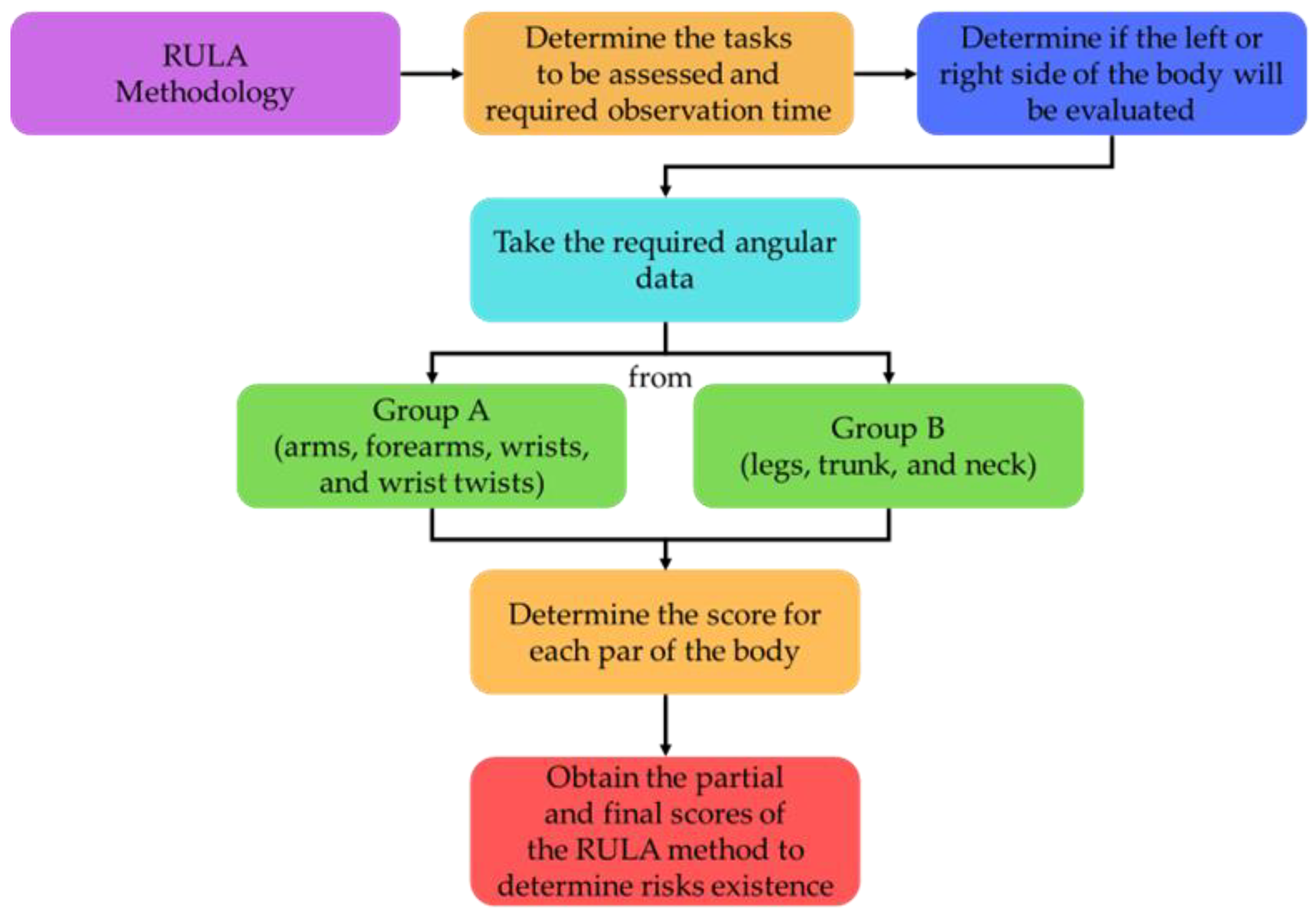
2.3. Ergonomics
2.4. Computer Vision System
3. Materials and Methods
3.1. Materials
- Universal Robots UR5—is a collaborative robot (cobot) with six degrees of freedom with a highly flexible robotic arm that enables safe automation of repetitive, risky tasks [22];
- RG2 by “On Robot”—is a flexible 2-finger robot gripper. It was used to simulate the gripper that will place the cable ties; and
- Cognex Camera IS7905M—is a camera commonly used in computer vision applications in the industry because of its small size and modularity. Additionally, it allows a quick and precise inspection and detection of workpieces [34].
3.2. Methods
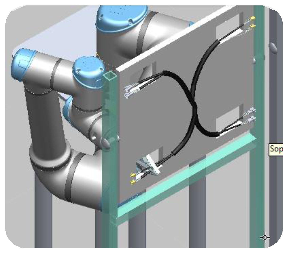
4. Case Study
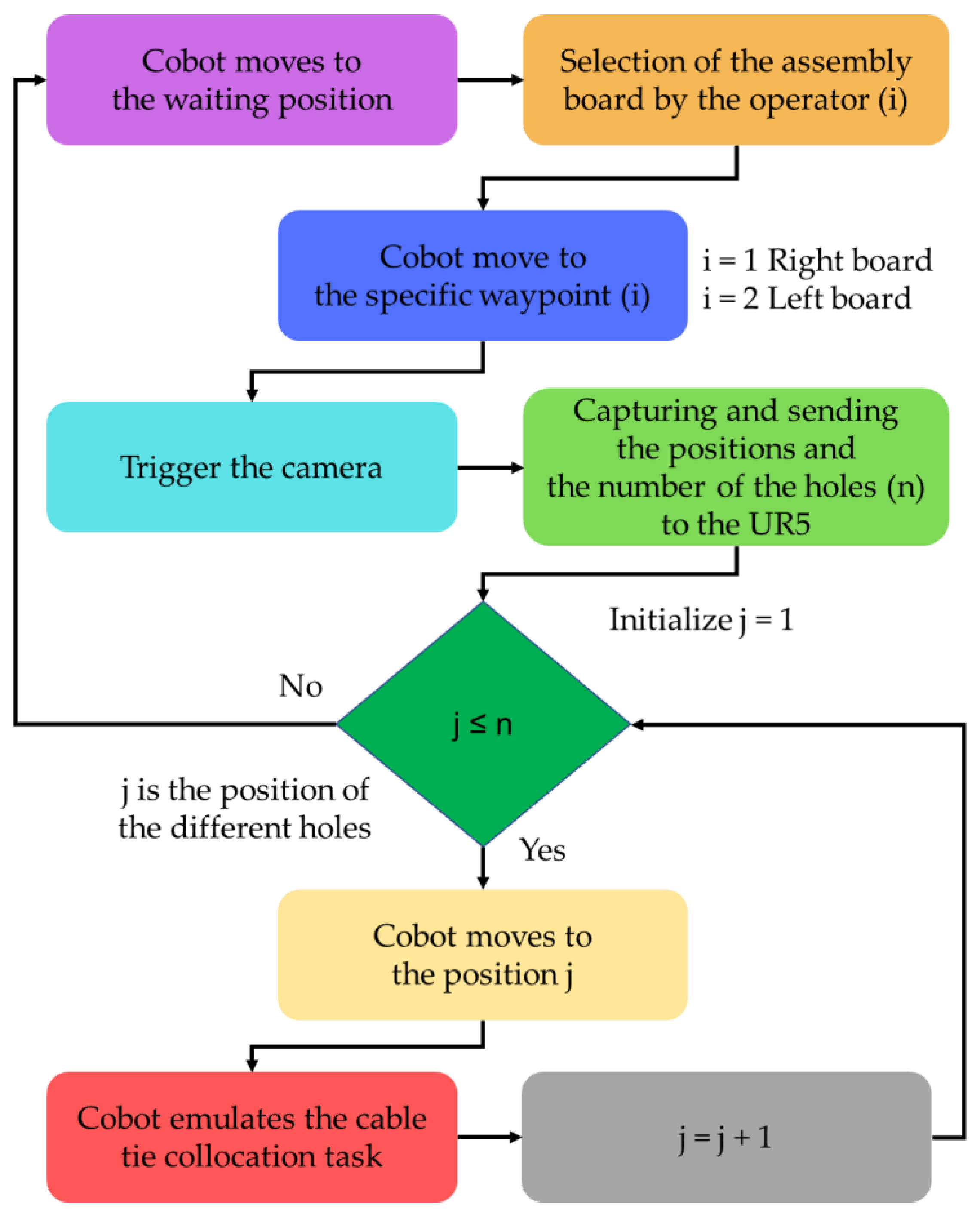
4.1. Collaborative Robot Programming
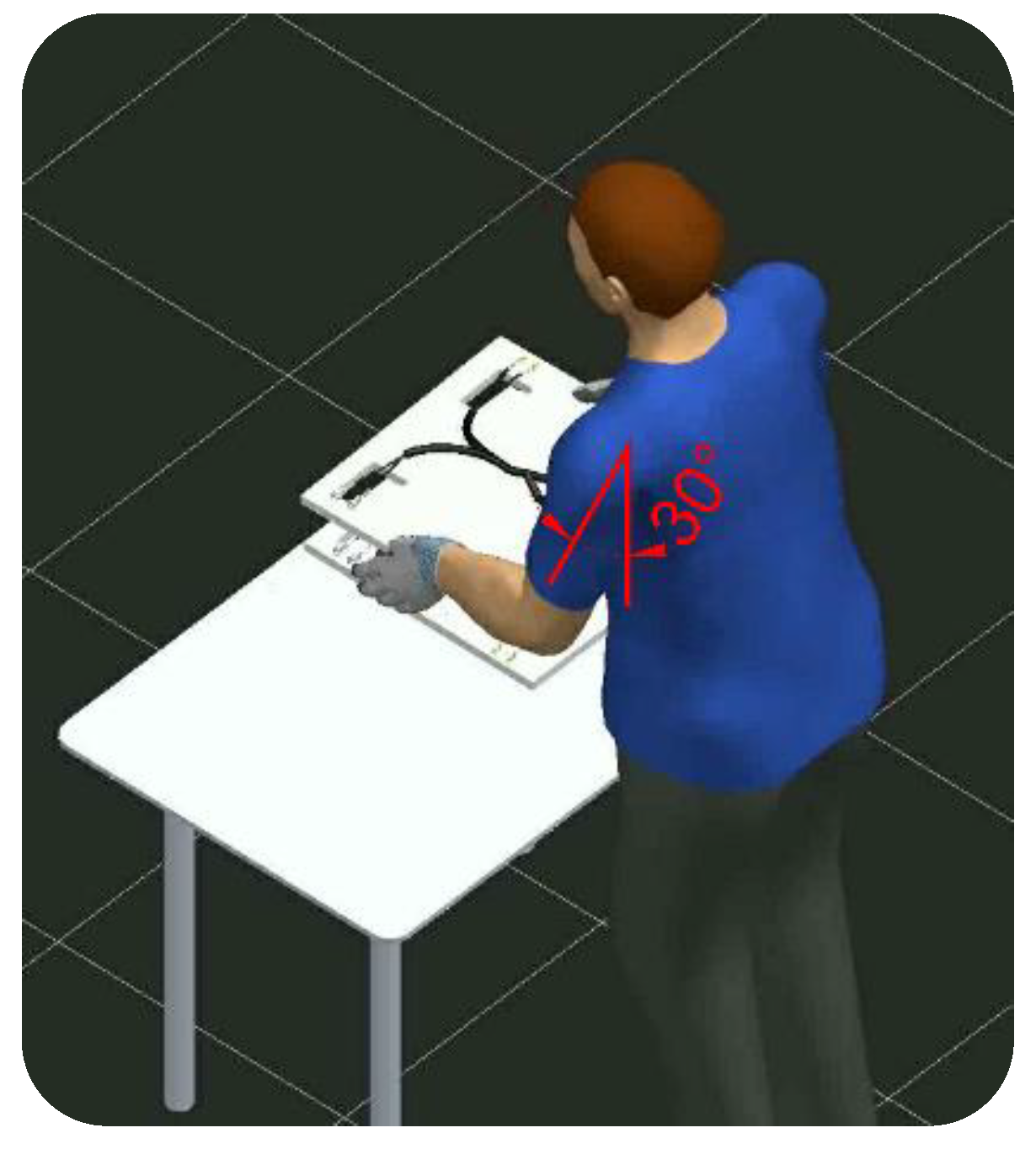
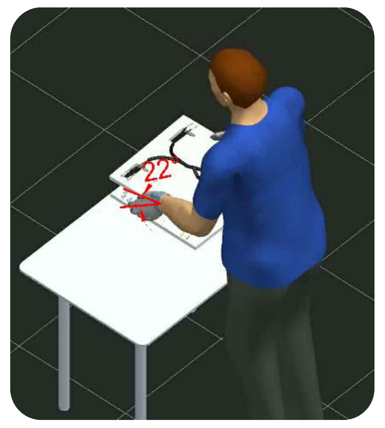
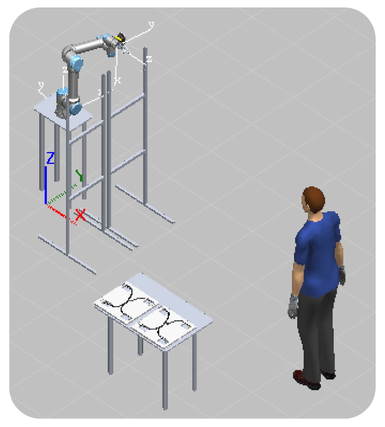
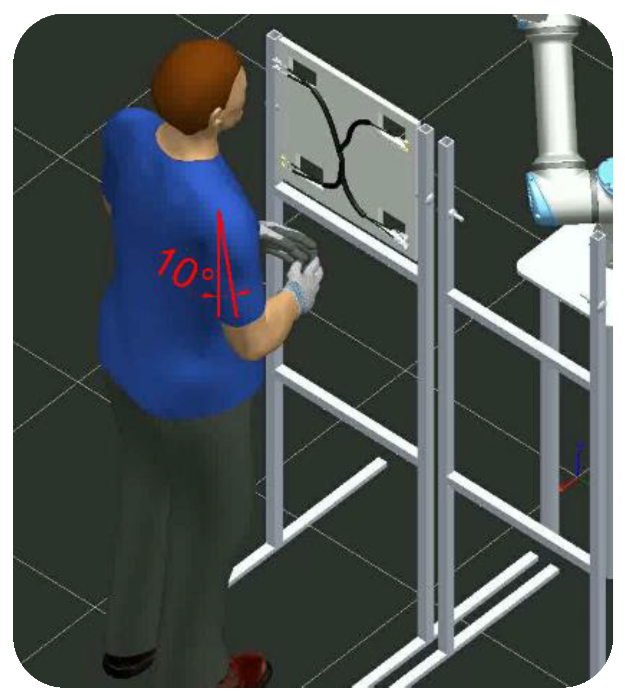
4.2. Ergonomic Evaluation with the Cobot
5. Discussion
6. Conclusions
Author Contributions
Funding
Institutional Review Board Statement
Informed Consent Statement
Data Availability Statement
Acknowledgments
Conflicts of Interest
References
- Realyvásquez-Vargas, A.; Arredondo-Soto, K.C.; García-Alcaraz, J.L.; Márquez-Lobato, B.Y.; Cruz-García, J. Introduction and Configuration of a Collaborative Robot in an Assembly Task as a means to Decrease Occupational Risks and Increase Efficiency in a Manufacturing Company. Robot. Comput. Integr. Manuf. 2019, 57, 315–328. [Google Scholar] [CrossRef]
- Gannon, M. Making Connector Assembly Safer, Efficient with Workplace Ergonomics. Connector Tips. 2019. Available online: https://www.connectortips.com/making-connector-assembly-safer-and-more-efficient-with-workplace-ergonomics/ (accessed on 11 November 2022).
- Aguirre, E.; Ferreira, L.; Raucent, B. Robotic Assembly of Wire Harnesses: Economic and Technical Justification. J. Manuf. Syst. 1997, 16, 220–231. [Google Scholar] [CrossRef]
- Gualtieri, L.; Palomba, I.; Merati, F.A.; Rauch, E.; Vidoni, R. Design of Human-centered Collaborative Assembly Workstations for the Improvement of Operators’ Physical Ergonomics and Production Efficiency: A Case Study. Sustainability 2020, 12, 3606. [Google Scholar] [CrossRef]
- Coban, M.; Gelen, G. Realization of Human-Robot Collaboration in Hybrid Assembly Systems by Using Wearable Technology. In Proceedings of the 6th International Conference on Control Engineering and Information Technology (CEIT), Istanbul, Turkey, 25–27 October 2018; pp. 25–27. [Google Scholar]
- Trommnau, J.; Frommknecht, A.; Siegert, J.; Wößner, J.; Bauernhansl, T. Design for Automatic Assembly: A New Approach to Classify Limp Components. Procedia CIRP 2020, 91, 49–54. [Google Scholar] [CrossRef]
- Heisler, P.; Utsch, D.; Kuhn, M.; Franke, J. Optimization of Wire Harness Assembly using Human-Robot-Collaboration. Procedia CIRP 2020, 97, 260–265. [Google Scholar] [CrossRef]
- Navas-Reascos, G.E.; Romero, D.; Stahre, J.; Caballero-Ruiz, A. Wire Harness Assembly Process Supported by Collaborative Robots: Literature Review and Call for R&D. Robotics 2022, 11, 65. [Google Scholar]
- Ibáñez, V.R.; Pujol, F.; Ortega, S.G.; Perpiñán, J.S. Collaborative Robotics in Wire Harnesses Spot Taping Process. Comput. Ind. 2021, 125, 103370. [Google Scholar] [CrossRef]
- Tunstel, E.; Dani, A.; Martinez, C.; Blakeslee, B.; Mendoza, J.; Saltus, R.; Trombetta, D.; Rotithor, G.; Fuhlbrigge, T.; Lasko, D.; et al. Robotic Wire Pinning for Wire Harness Assembly Automation. In Proceedings of the 2020 IEEE/ASME International Conference on Advanced Intelligent Mechatronics (AIM), Boston, MA, USA, 6–10 July 2020; pp. 1208–1215. [Google Scholar]
- Yumbla, F.; Yi, J.S.; Abayebas, M.; Shafiyev, M.; Moon, H. Tolerance Dataset: Mating Process of Plug-in Cable Connectors for Wire Harness Assembly Tasks. Intell. Serv. Robot. 2020, 13, 159–168. [Google Scholar] [CrossRef]
- Nguyen, T.P.; Yoon, J. A Novel Vision-based Method for 3D Profile Extraction of Wire harness in Robotized Assembly Process. J. Manuf. Syst. 2021, 61, 365–374. [Google Scholar] [CrossRef]
- Heisler, P.; Steinmetz, P.; Yoo, I.S.; Franke, J. Automatization of the Cable-Routing-Process within the Automated Production of Wiring Systems. Appl. Mech. Mater. 2017, 871, 186–192. [Google Scholar] [CrossRef]
- Trommnau, J.; Kühnle, J.; Siegert, J.; Inderka, R.; Bauernhans, T. Overview of the State of the Art in the Production Process of AutomotiveWire Harnesses, Current Research and Future Trends. Procedia CIRP 2019, 81, 387–392. [Google Scholar] [CrossRef]
- Capitanelli, A.; Maratea, M.; Mastrogiovanni, F.; Vallati, M. On the Manipulation of Articulated Objects in Human-Robot Cooperation Scenarios. Rob. Auton. Syst. 2018, 109, 139–155. [Google Scholar] [CrossRef] [Green Version]
- Sugiono, S.; Efranto, R.Y.; Budiprasetya, A.R. Reducing Musculoskeletal Disorder (MSD) Risk of Wiring Harness Workstation using Workplace Ergonomic Risk Assessment (WERA) Method. Sci. Rev. Eng. Environ. Sci. 2018, 27, 536–551. [Google Scholar] [CrossRef]
- Aguirre, E.; Raucent, B. Economic Comparison of Wire Harness Assembly Systems. J. Manuf. Syst. 1994, 13, 276–288. [Google Scholar] [CrossRef]
- Yumbla, F.; Abeyabas, M.; Luong, T.; Yi, J.S.; Moon, H. Preliminary Connector Recognition System based on Image Processing for Wire Harness Assembly Tasks. In Proceedings of the 20th International Conference on Control, Automation and Systems (ICCAS), Busan, Republic of Korea, 13–16 October 2020; pp. 1146–1150. [Google Scholar]
- Rauch, E.; Linder, C.; Dallasega, P. Anthropocentric Perspective of Production before and within Industry 4.0. Comput. Ind. Eng. 2020, 139, 105644. [Google Scholar] [CrossRef]
- Rouse, M. Collaborative Robot (Cobot). 2018. Available online: https://whatis.techtarget.com/definition/collaborative-robot-cobot (accessed on 11 November 2022).
- Dobra, Z.; Dhir, K.S. Technology Jump in the Industry: Human-Robot Cooperation in Production. Ind. Robot Int. J. Robot. Res. Appl. 2020, 47, 757–775. [Google Scholar] [CrossRef]
- Faccio, M.; Bottin, M.; Rosati, G. Collaborative and Traditional Robotic Assembly: A Comparison Model. Int. J. Adv. Manuf. Technol. 2019, 102, 1355–1372. [Google Scholar] [CrossRef]
- Universal Robots (UR). Why Cobots? 2021. Available online: https://www.universal-robots.com/products/collaborative-robots-cobots-benefits/ (accessed on 11 November 2022).
- Wired Workers. Universal Robots UR5. 2020. Available online: https://wiredworkers.io/universal-robots-ur5/#:~:text= (accessed on 11 November 2022).
- El Zaatari, S.; Marei, M.; Li, W.; Usman, Z. Cobot Programming for Collaborative Industrial Tasks: An Overview. Rob. Auton. Syst. 2019, 116, 162–180. [Google Scholar] [CrossRef]
- Cesta, A.; Orlandini, A.; Bernardi, G.; Umbrico, A. Towards a Planning-based Framework for Symbiotic Human-Robot Collaboration. In Proceedings of the IEEE 21st International Conference Emerging Technologies and Factory Automation (ETFA), Berlin, Germany, 6–9 September 2016; pp. 1–8. [Google Scholar]
- Universidad Politécnica de Valencia (UPV). RULA. 2021. Available online: https://www.ergonautas.upv.es/metodos/rula/rula-ayuda.php (accessed on 11 November 2022).
- Universidad Politécnica de Valencia (UPV). JSI. 2021. Available online: https://www.ergonautas.upv.es/metodos/jsi/jsi-ayuda.php (accessed on 11 November 2022).
- Brownlee, J. Machine Learning Mastery. 2019. Available online: https://machinelearningmastery.com/what-is-computer-vision/ (accessed on 11 November 2022).
- Tsarouchi, P.; Makris, S.; Chryssolouris, G. Human–Robot Interaction Review and Challenges on Task Planning and Programming. Int. J. Comput. Integr. Manuf. 2016, 29, 916–931. [Google Scholar] [CrossRef]
- Voulodimos, A.; Doulamis, N.; Doulamis, A.; Protopapadakis, E. Deep Learning for Computer Vision: A Brief Review. Comput. Intell. Neurosci. 2018, 2018, 7068349. [Google Scholar] [CrossRef] [PubMed]
- Lim, J.H.; Kuc, T.Y. Intelligent Hybrid Hierarchical Architecture based Object Recognition system for Robust Robot Vision. In Proceedings of the International Conference on Control, Automation and Systems (ICCAS), Seoul, Republic of Korea, 14–17 October 2008; pp. 2130–2133. [Google Scholar]
- Oliver, N.; Rosario, B.; Pentland, A. A Bayesian Computer Vision System for Modeling Human Interactions. Lect. Notes Comput. Sci. 1999, 1542, 255–272. [Google Scholar]
- Corporation, C. Especificaciones IN-SIGHT 7000. 2020. Available online: https://www.cognex.com/es-mx/products/machine-vision/2d-machine-vision-systems/in-sight-7000-series/specifications (accessed on 11 November 2022).


| Score | Performance |
|---|---|
| 1 or 2 | Acceptable risk. |
| 3 or 4 | Changes to the task may be required; it is convenient to deepen the study. |
| 5 or 6 | Task redesign required. |
| 7 | Urgent changes are required in the task. |
| Score A | Score B | ||||||
|---|---|---|---|---|---|---|---|
| 1 | 2 | 3 | 4 | 5 | 6 | 7 | |
| 1 | 1 | 2 | 3 | 3 | 4 | 5 | 5 |
| 2 | 2 | 2 | 3 | 4 | 4 | 5 | 5 |
| 3 | 3 | 3 | 3 | 4 | 4 | 5 | 6 |
| 4 | 3 | 3 | 3 | 4 | 5 | 6 | 6 |
| 5 | 4 | 4 | 4 | 5 | 6 | 7 | 7 |
| 6 | 4 | 4 | 5 | 6 | 6 | 7 | 7 |
| 7 | 5 | 5 | 6 | 6 | 7 | 7 | 7 |
| 8 | 5 | 5 | 6 | 7 | 7 | 7 | 7 |
| Method | Manual Assembly | Collaborative Assembly |
|---|---|---|
| RULA | 7 | 4 |
| JSI | 12 | 4.5 |
Publisher’s Note: MDPI stays neutral with regard to jurisdictional claims in published maps and institutional affiliations. |
© 2022 by the authors. Licensee MDPI, Basel, Switzerland. This article is an open access article distributed under the terms and conditions of the Creative Commons Attribution (CC BY) license (https://creativecommons.org/licenses/by/4.0/).
Share and Cite
Navas-Reascos, G.E.; Romero, D.; Rodriguez, C.A.; Guedea, F.; Stahre, J. Wire Harness Assembly Process Supported by a Collaborative Robot: A Case Study Focus on Ergonomics. Robotics 2022, 11, 131. https://doi.org/10.3390/robotics11060131
Navas-Reascos GE, Romero D, Rodriguez CA, Guedea F, Stahre J. Wire Harness Assembly Process Supported by a Collaborative Robot: A Case Study Focus on Ergonomics. Robotics. 2022; 11(6):131. https://doi.org/10.3390/robotics11060131
Chicago/Turabian StyleNavas-Reascos, Gabriel E., David Romero, Ciro A. Rodriguez, Federico Guedea, and Johan Stahre. 2022. "Wire Harness Assembly Process Supported by a Collaborative Robot: A Case Study Focus on Ergonomics" Robotics 11, no. 6: 131. https://doi.org/10.3390/robotics11060131