Figure 1.
(
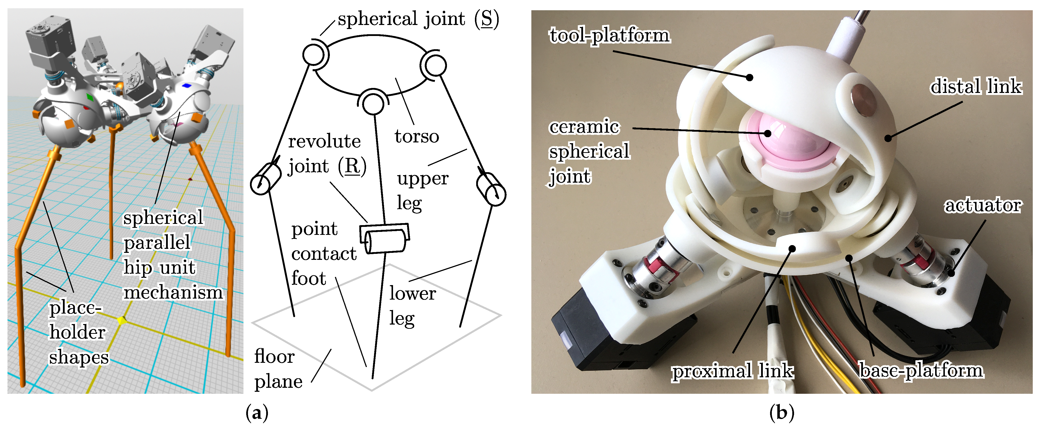
a) Preliminary three-legged robot model.
Left: 3D-model used in the simulation, featuring CAD-based hip mechanisms and simplified leg shapes.
Right: Joint and body topology of the robot. (
b) Real-world SPM hip unit actuated with Dynamixel Servos, including 3D-printed parts, stiff aluminium support structures, and the ceramic artificial load-support joint in the SPM centre. Multiple videos of the moving prototype model are included in the
Supplementary Materials.
Figure 1.
(
a) Preliminary three-legged robot model.
Left: 3D-model used in the simulation, featuring CAD-based hip mechanisms and simplified leg shapes.
Right: Joint and body topology of the robot. (
b) Real-world SPM hip unit actuated with Dynamixel Servos, including 3D-printed parts, stiff aluminium support structures, and the ceramic artificial load-support joint in the SPM centre. Multiple videos of the moving prototype model are included in the
Supplementary Materials.
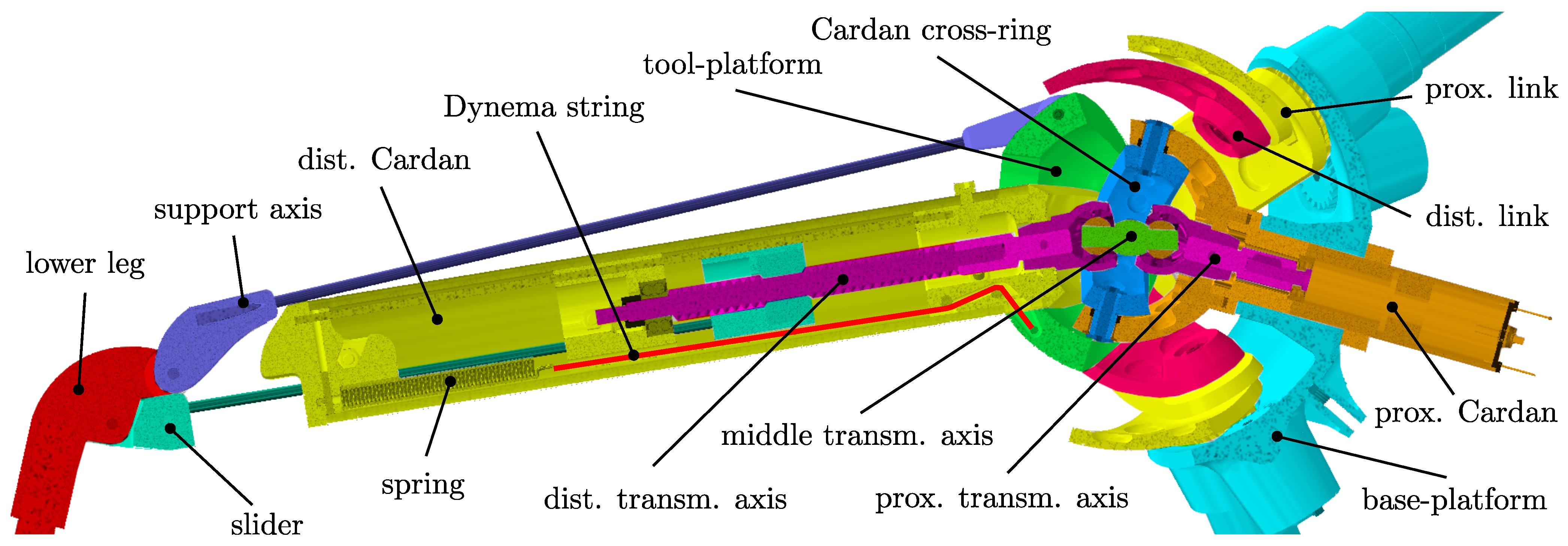
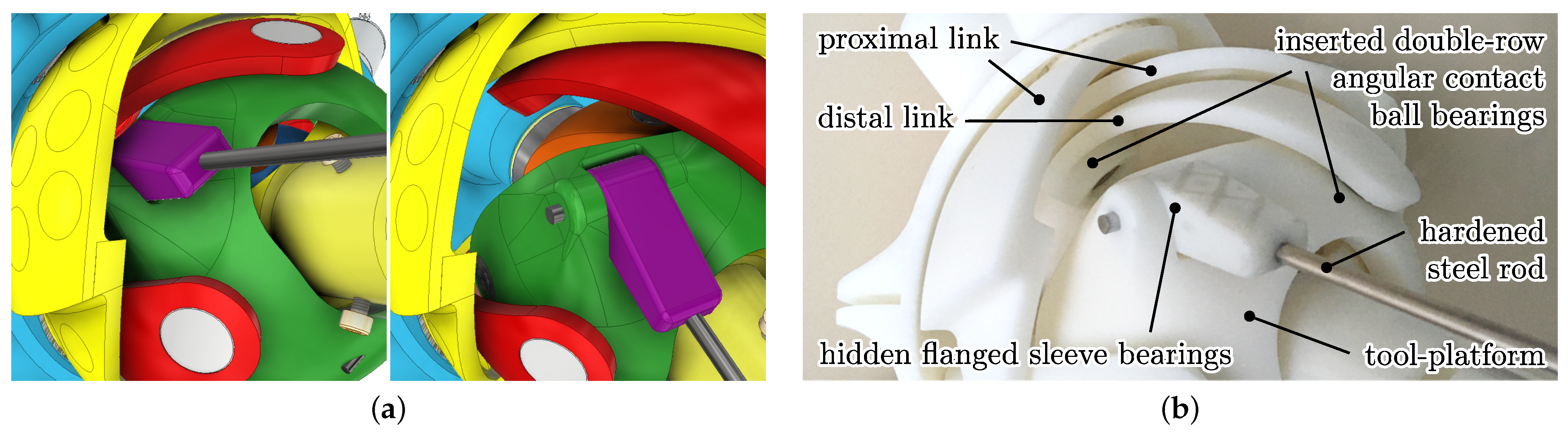
Figure 2.
Cutaway view of the leg CAD model highlighting individual assemblies that are treated as rigid bodies, connected by joints. The figure also shows the naming convention for parts that are referred to in this article.
Figure 2.
Cutaway view of the leg CAD model highlighting individual assemblies that are treated as rigid bodies, connected by joints. The figure also shows the naming convention for parts that are referred to in this article.
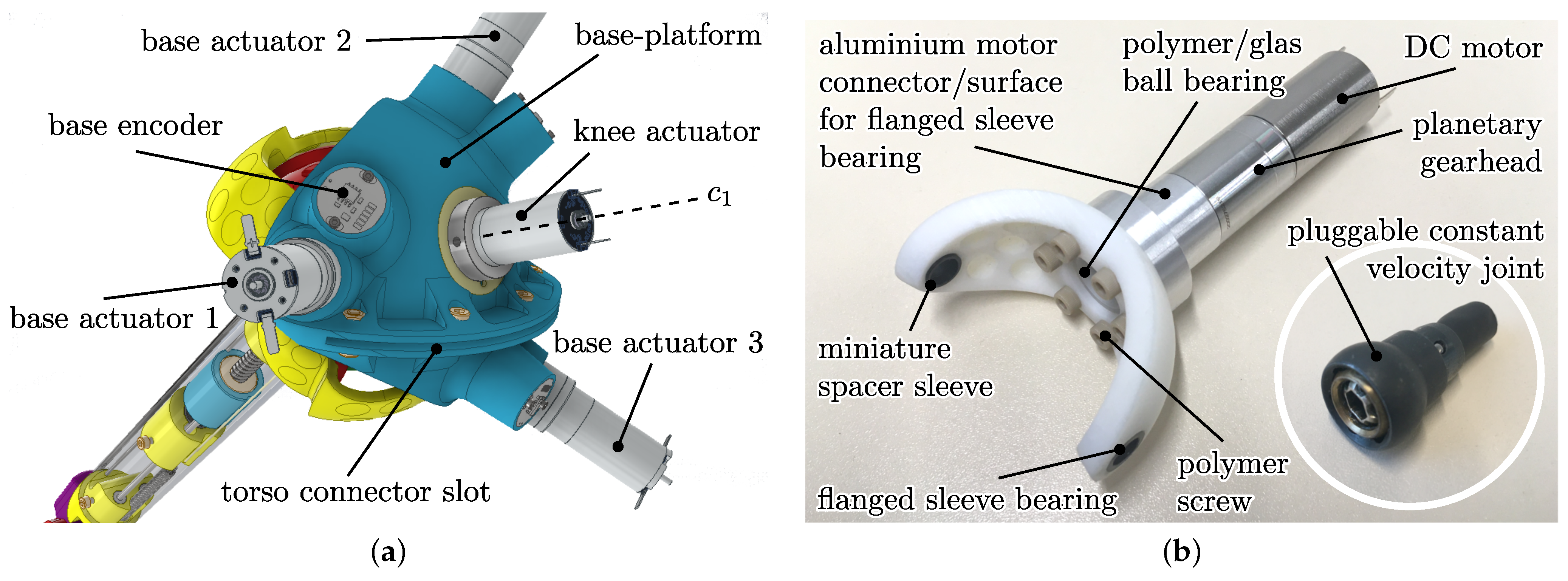
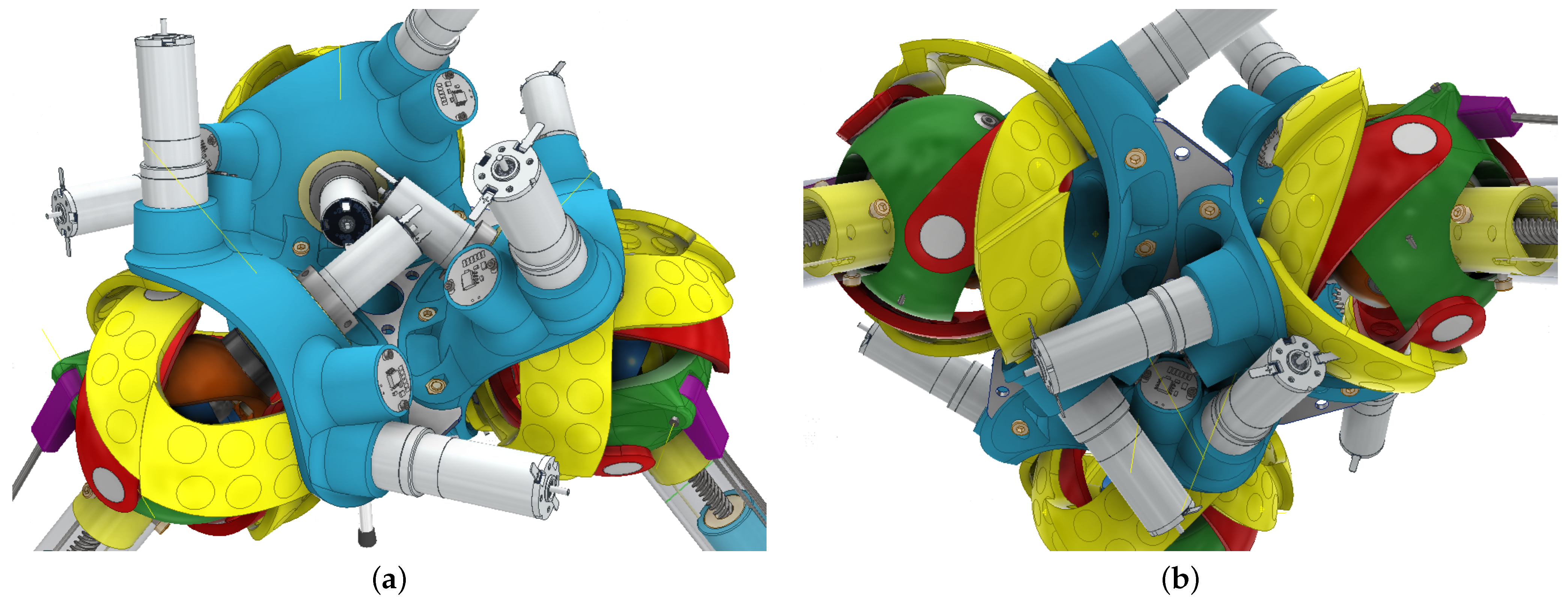
Figure 3.
(a) Coloured CAD model of the rear side, showing the three base actuators and the knee actuator. All actuator axes intersect in the SPM centre. The knee actuator is fixed to the proximal Cardan part, which is connected with a rotatory bushing joint to the base-platform. (b) Photograph of the proximal Cardan part, containing the fixed knee actuator and the pluggable homokinetic (constant-velocity) coupling for the articulated central axis that drives the knee joint slider mechanism.
Figure 4.
(a) Hip reference frame, fixed to the base-platform. Red, green, and blue axes represent the x-, y-, and z- axes of the orthogonal reference system. Bold lines refer to the base-platform (hb) system and thin lines to the tool-platform (hf) system. Black lines depict the actuator (base) axes. Other axes are the link (cyan) and tool (magenta) axes. (b) Assembly depiction of the three connected SPM modules with the torso reference frame (ee) in the centre, also showing the collision-free arrangement of the motor axes.
Figure 5.
Top view (a) and bottom view (b) of the interlocking design. The distance between the vertical symmetry axis placed through the centre of the robot torso and the individual hip centre points is expressed by the radius . Due to the slight angular offset of each SPM, the actuators are arranged without mechanically obstructing each other or moving parts.
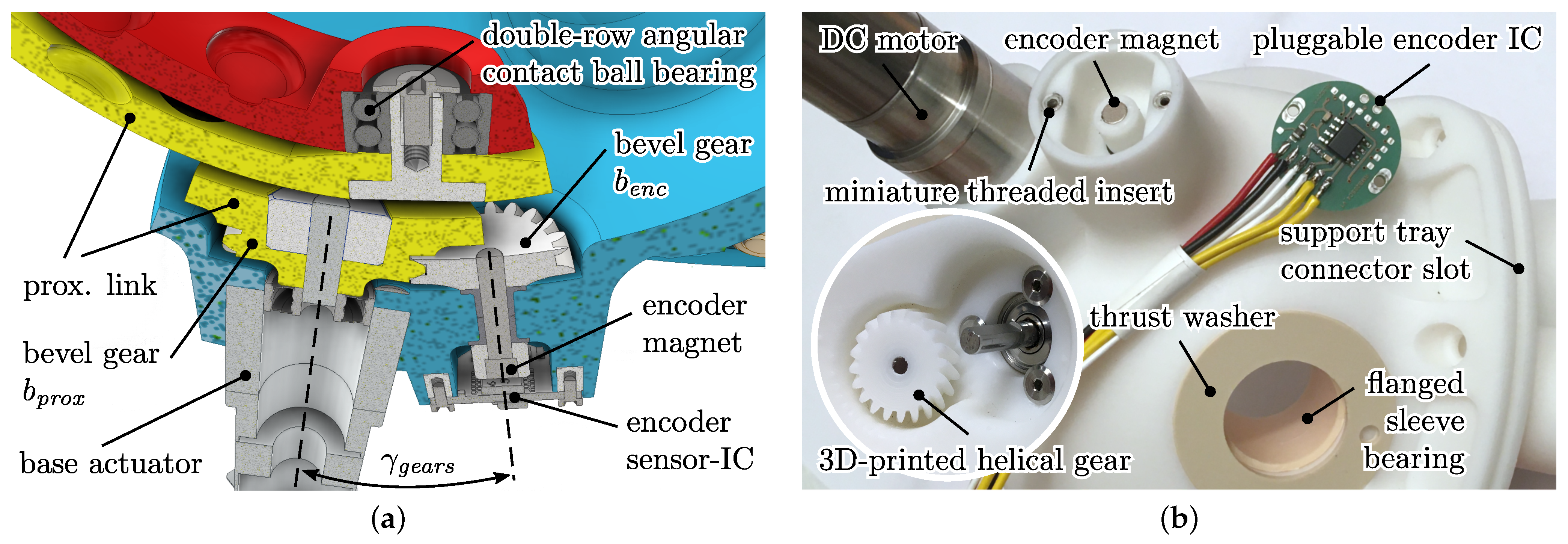
Figure 6.
(a) Cutaway view of the motor to encoder bevel gear construction. The bevel gears comprise helical teeth with a helix angle of . Both gears themselves are cuttings of a spherical shell shape; thus, e.g., the front side of the small bevel gear is spherically shaped; hence, there is no obstruction with the equally spherical shape of the proximal link. (b) Backside of the real-world 3D-printed base-platform showing the encoder integration. The detail picture depicts the inner side, showing a close-up of the motor integration and the encoder bevel gear, printed with a layer resolution of on the stereolithography based 3D printer Formlabs Form 2.
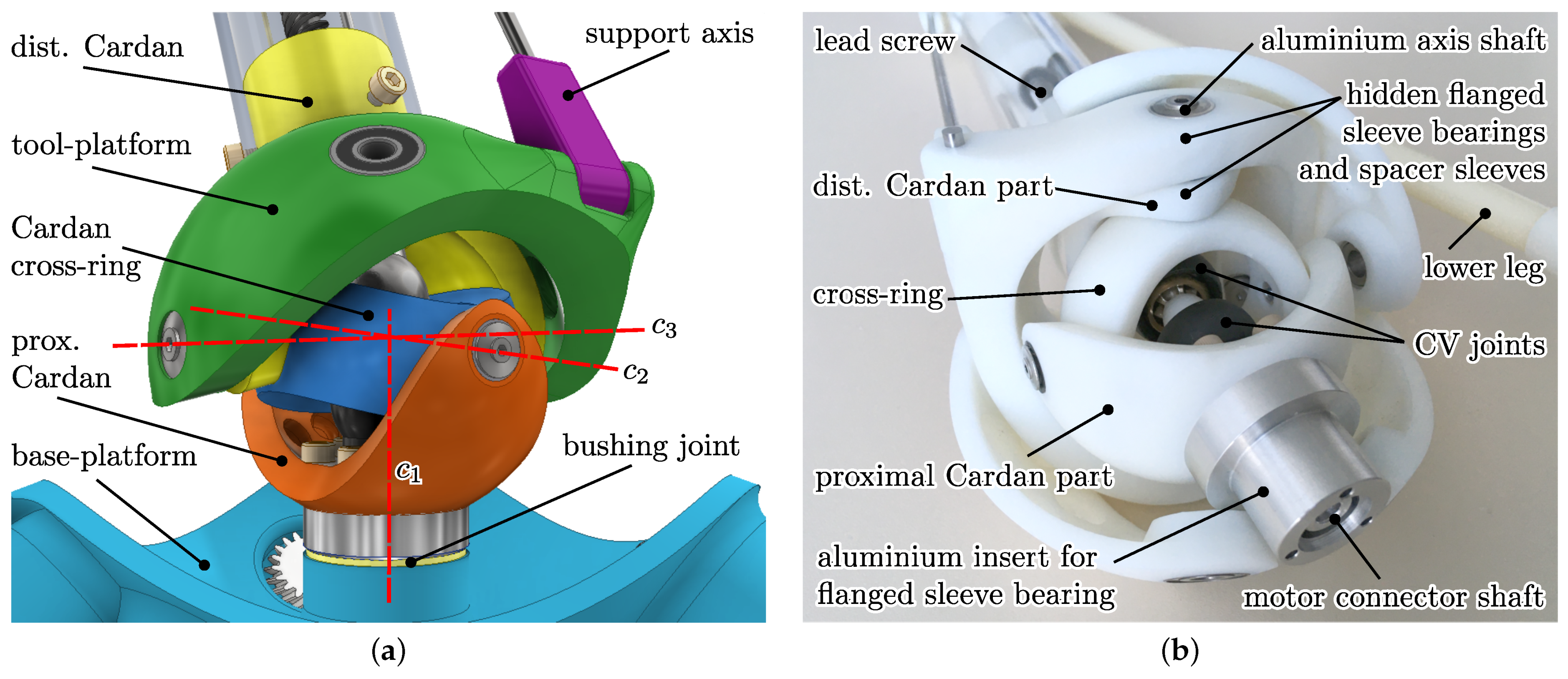
Figure 7.
(a) Coloured CAD model of the Cardan section, depicting the joint axes –. Proximal and distal links of the SPM are not displayed. (b) Real-world model of the section, showing the mechanism in the assembled prototype with its pluggable motor connection shaft, containing 3D-printed and aluminium structural parts, and the hidden plastic bushings used for low-friction joints.
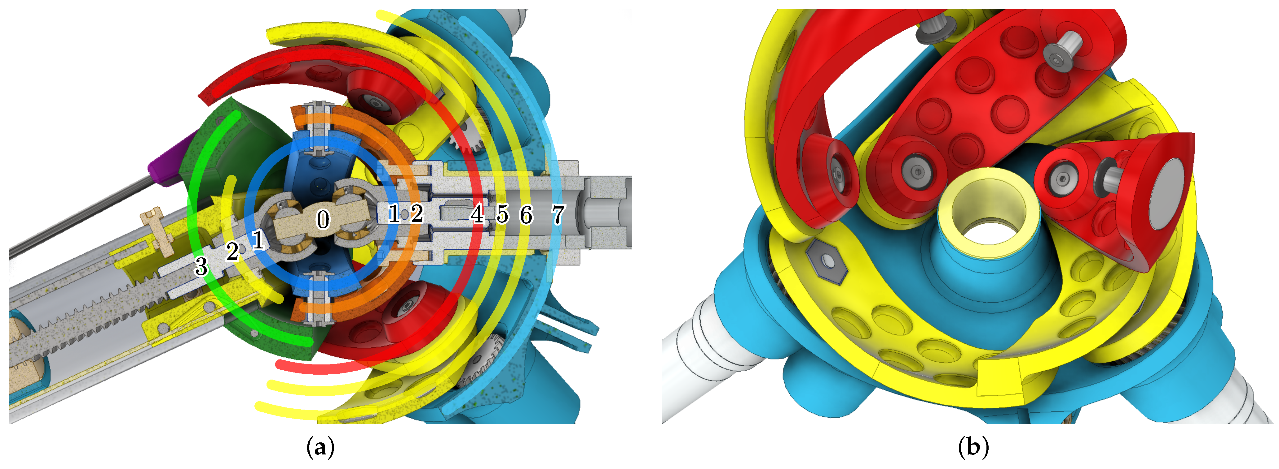
Figure 8.
(a) Cutaway view and schematic depiction of the individual spherical Layers 0–7 of the rotating parts. Some parts share the same layer, which causes collisions in certain poses or marks workspace limitations. (b) Collision-free pose of the proximal links inside the base-platform at the rotated tool-platform. Only the base-platform, proximal, and distal links are displayed. Recesses are employed for weight reduction.
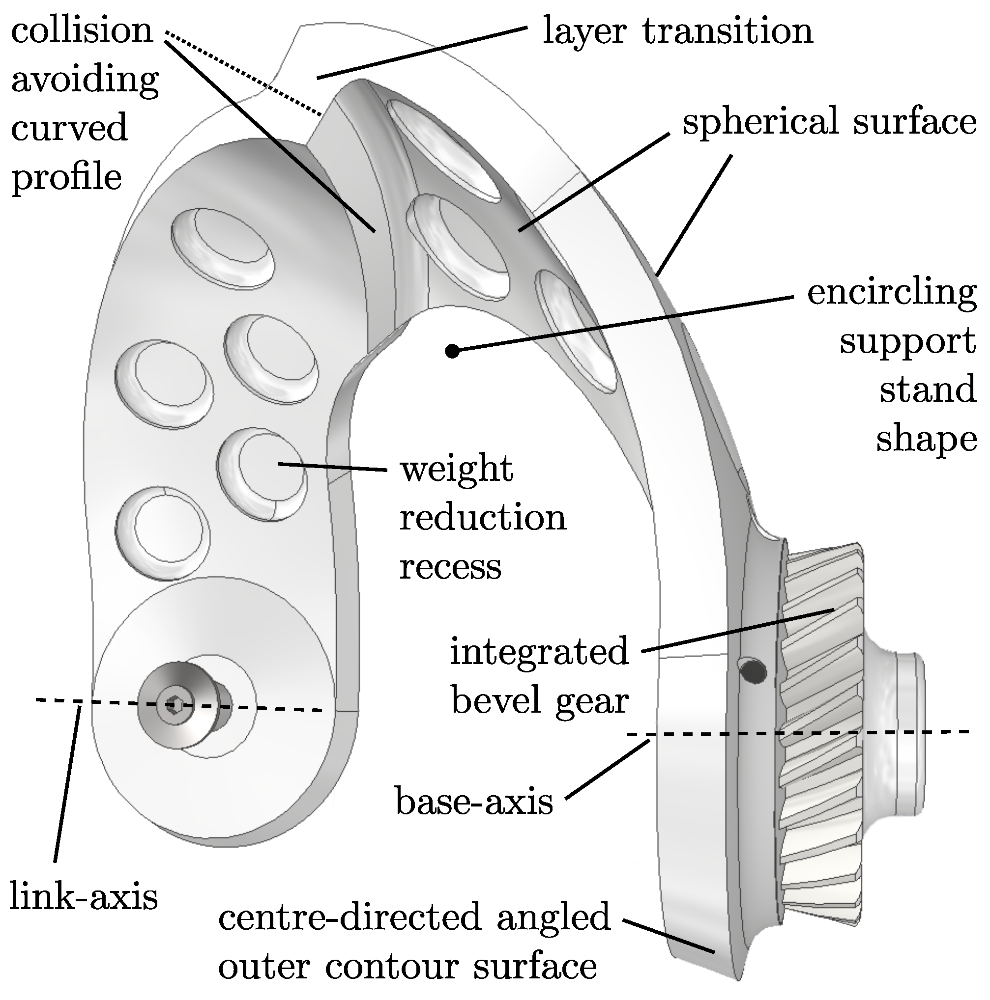
Figure 9.
CAD model of a single proximal link. Each point of the surface is directed either vertical or tangential to the SPM centre, minimizing any possible interactions with other geometries and only allowing for surface tangential internal collisions, maximizing the contact plane.
Figure 9.
CAD model of a single proximal link. Each point of the surface is directed either vertical or tangential to the SPM centre, minimizing any possible interactions with other geometries and only allowing for surface tangential internal collisions, maximizing the contact plane.
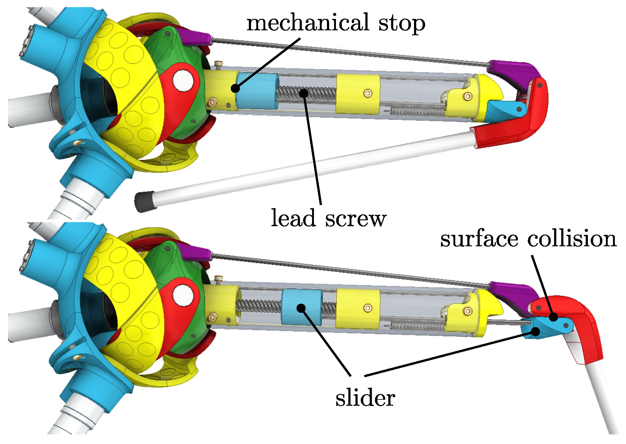
Figure 10.
Retracted (top) and expanded (bottom) pose. Base actuators are locked; therefore, only the knee actuator DOF is shown. The retracted pose is limited by a mechanical stop of the slider, and the expanded pose stops at the collision of the lower leg and slider assembly.
Figure 10.
Retracted (top) and expanded (bottom) pose. Base actuators are locked; therefore, only the knee actuator DOF is shown. The retracted pose is limited by a mechanical stop of the slider, and the expanded pose stops at the collision of the lower leg and slider assembly.
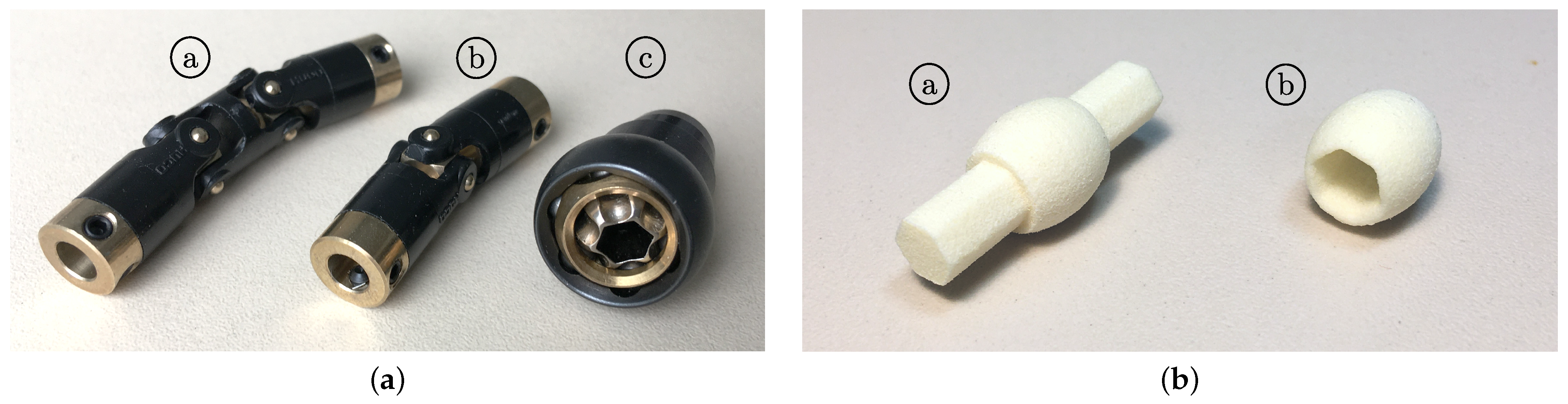
Figure 11.
(
a) Size and type comparison of available exemplary miniature couplings: Huco double universal joint, made of acetal/brass ⓐ [
41], Huco single universal joint ⓑ, and TVR Ball-X CV homokinetic Rzeppa-type joint ⓒ [
42]. (
b) The 3D-printed hexagonal middle transmission axis for normal operation ⓐ and the hollow version ⓑ for the combination with a heavy-duty metallic transmission shaft.
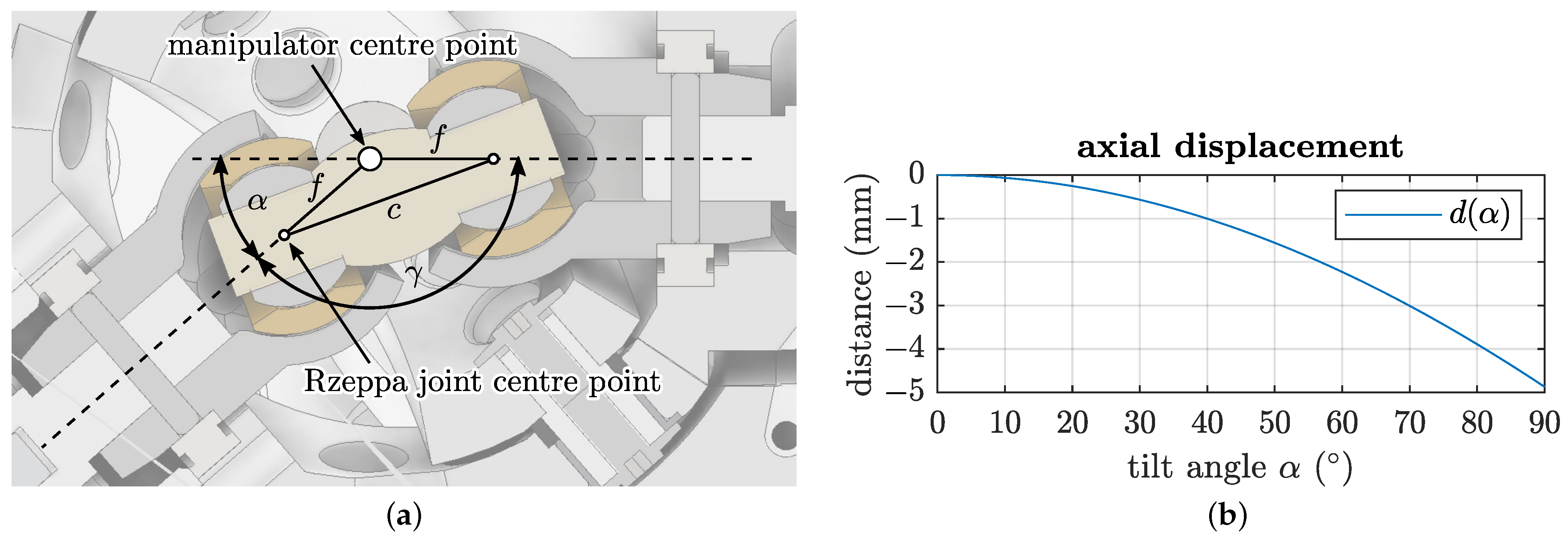
Figure 12.
(a) Cutaway view and geometric dependencies of the double Rzeppa constant velocity () transmission joint. Both joints are connected with R joints to the upper leg, respectively the proximal Cardan part, while the plastic centre part connects both joints with P joints. (b) Required relative axial displacement of the Rzeppa centre points in dependence of the SPM manipulator tilt angle for the model-specific value .
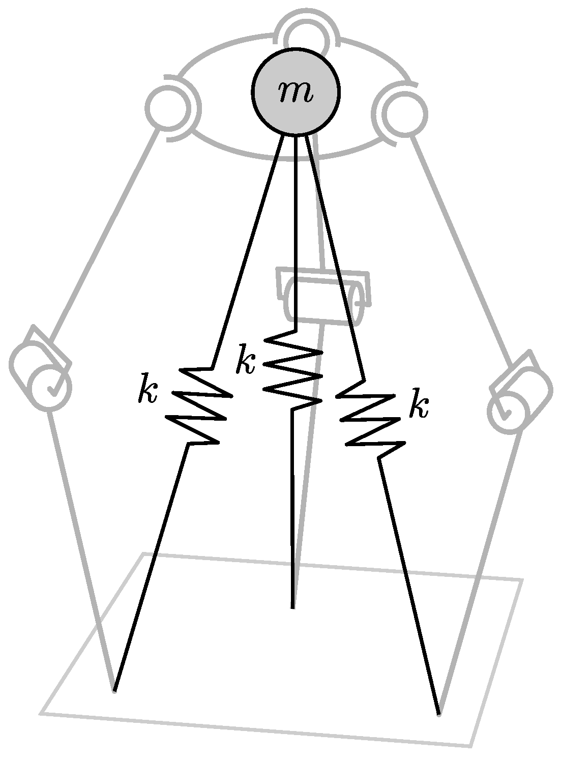
Figure 13.
Targeted approximation of the SLIP model. The three-legged robot model (grey lines) should match as close as possible the depicted equivalent three-legged SLIP model (black lines) as shown above with spring stiffness k and main body mass m.
Figure 13.
Targeted approximation of the SLIP model. The three-legged robot model (grey lines) should match as close as possible the depicted equivalent three-legged SLIP model (black lines) as shown above with spring stiffness k and main body mass m.
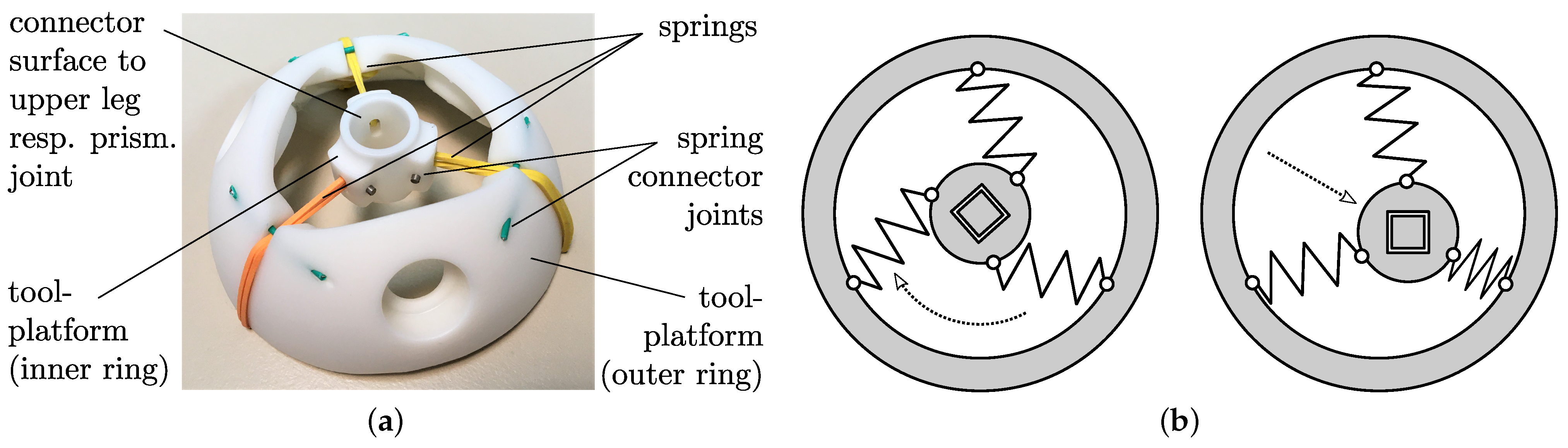
Figure 14.
(a) Prototype of the divided tool-platform for full rotatory motions of the inner ring with respect to the outer ring, as long as the mechanical construction allows for no collisions between bodies or hindering the free contractions and elongations of the springs. (b) Planar depiction of the motion capability. Thus, the effect of rotation axes parallel with the paper plane through the spherical centre of the SPM is omitted.
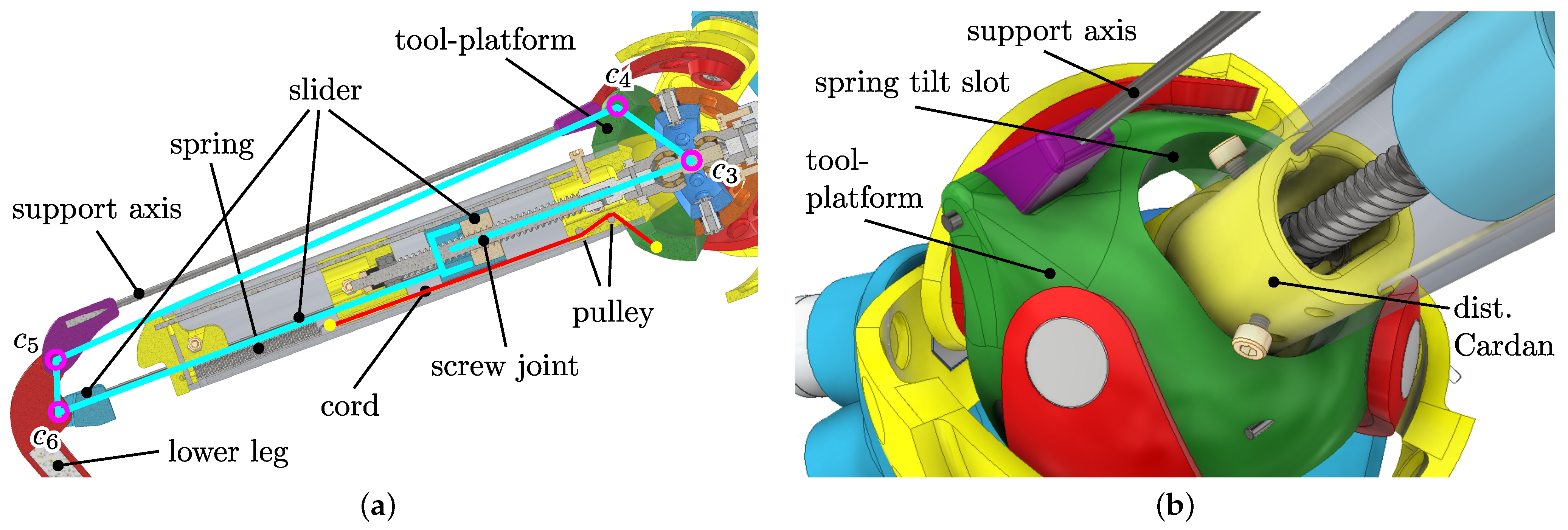
Figure 15.
(a) Kinematical relationship of the closed-loop structure for the implementation of the elastic leg behaviour in planar representation. All revolute axes – are parallel. Cyan marks the virtual polygon between joints. The red line shows the Dynema cord, connected at the yellow spots to the assemblies. (b) The distal Cardan part and tool-platform are able to independently rotate around the common axis , and the motion is only limited by the mechanical limits of the slot inside the tool-platform. Without external forces, a Dynema cord presses the distal Cardan part against the lower side of the slot surface, which fixes the undisturbed pose of the leg mechanism.
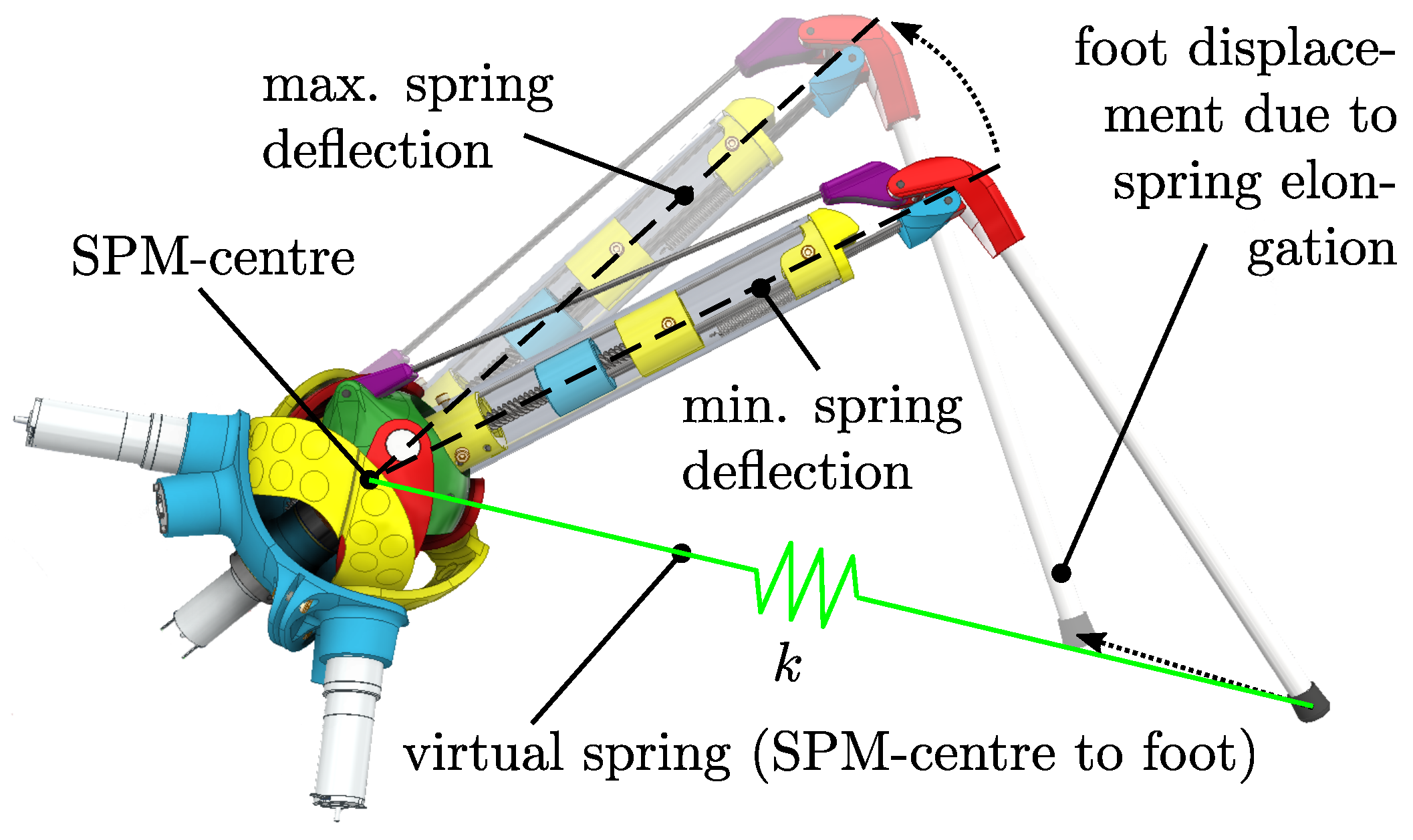
Figure 16.
Exemplary displacement of the foot tip position due to spring elongation. The angular positions of base and knee actuators are not changed between the minimal and maximal spring deflection poses; therefore, the pose differences are caused only by the spring DOF. The foot position is kept close to the virtual connection line between the uncompressed state and SPM centre in conjunction with the target SLIP model. The resulting virtual spring with stiffness k is shown in green.
Figure 17.
(a) Spatial position of the support axis joint for different extreme SPM orientations. Left: Sliding under the prox. link at upwards SPM rotation. Right: Using the space between distal links at SPM downwards rotation. (b) Real-world prototype.
Figure 17.
(a) Spatial position of the support axis joint for different extreme SPM orientations. Left: Sliding under the prox. link at upwards SPM rotation. Right: Using the space between distal links at SPM downwards rotation. (b) Real-world prototype.
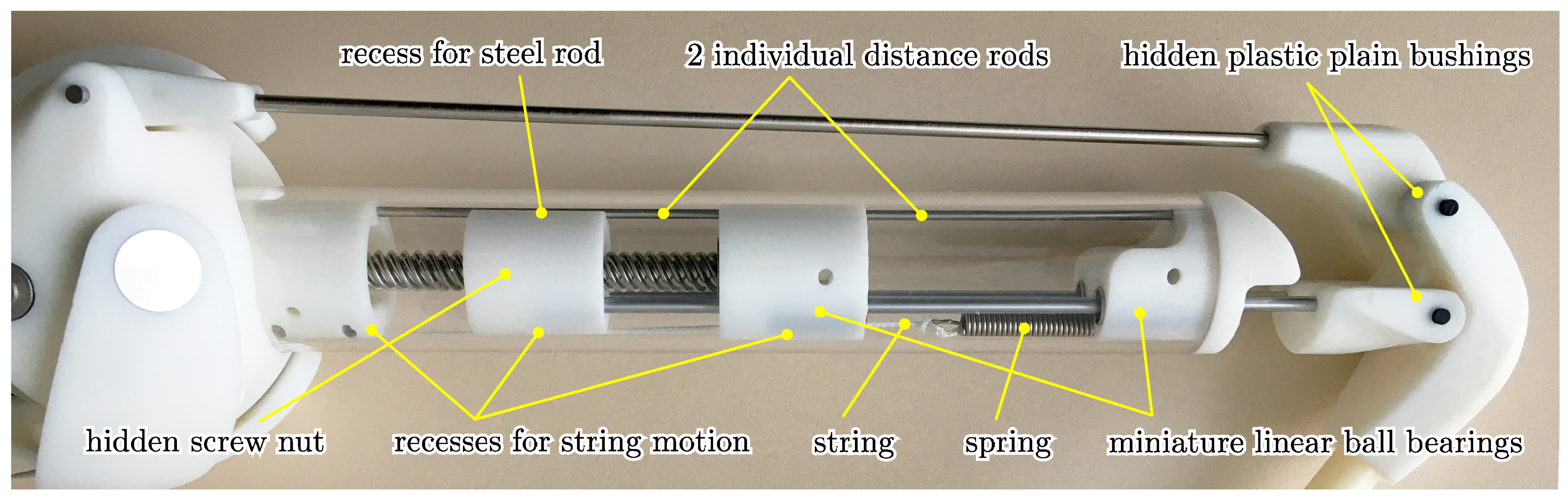
Figure 18.
Upper leg mechanism. Bars and bushings were press fit; thus, no additional gluing or screws were required. Due to the integrated design without any possibility to reach the inner parts inside the tube, the assembly of the leg requires multiple steps, including several partial back and forth pushes with partially disassembling and reassembling of the components, till all parts are fit together.
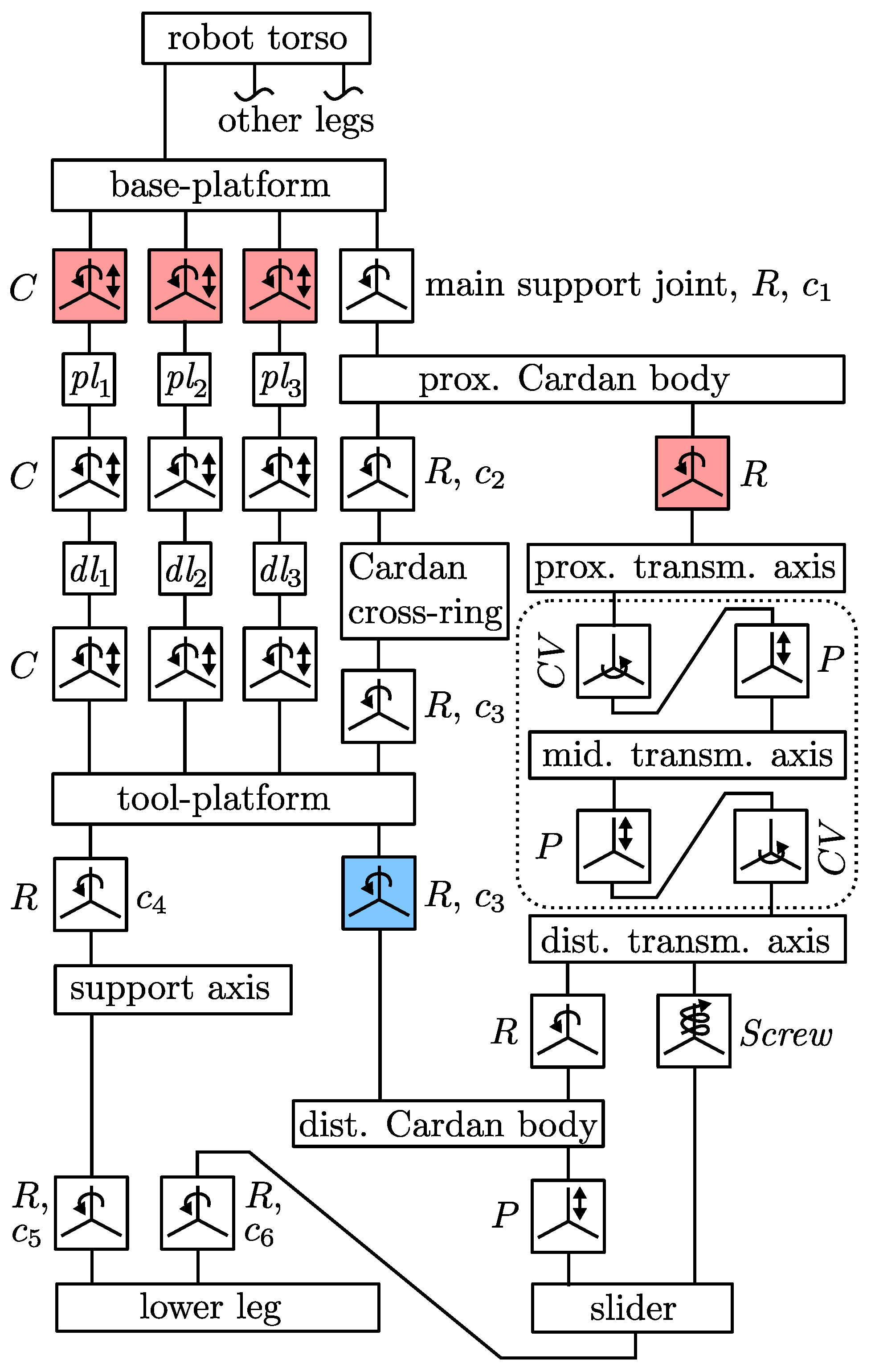
Figure 19.
Multi-body system of the robot model with the non-overconstrained SPM. Red joints are actuated. The blue joint depicts the passively applied torque due to the integrated mechanical spring. Dotted areas show components that were not modelled in the simulated system. Axes – are displayed at the respective joints.
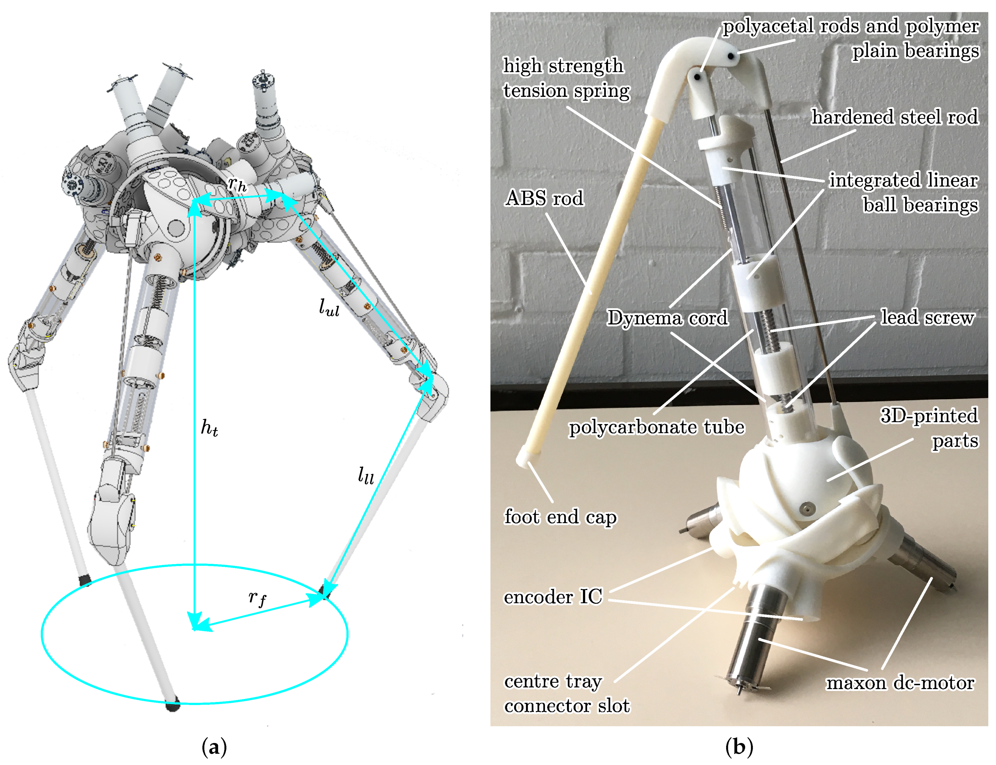
Figure 20.
(a) Complete CAD model of the robot, including geometric parameters. (b) Real-world prototype model of the robot leg.
Figure 20.
(a) Complete CAD model of the robot, including geometric parameters. (b) Real-world prototype model of the robot leg.
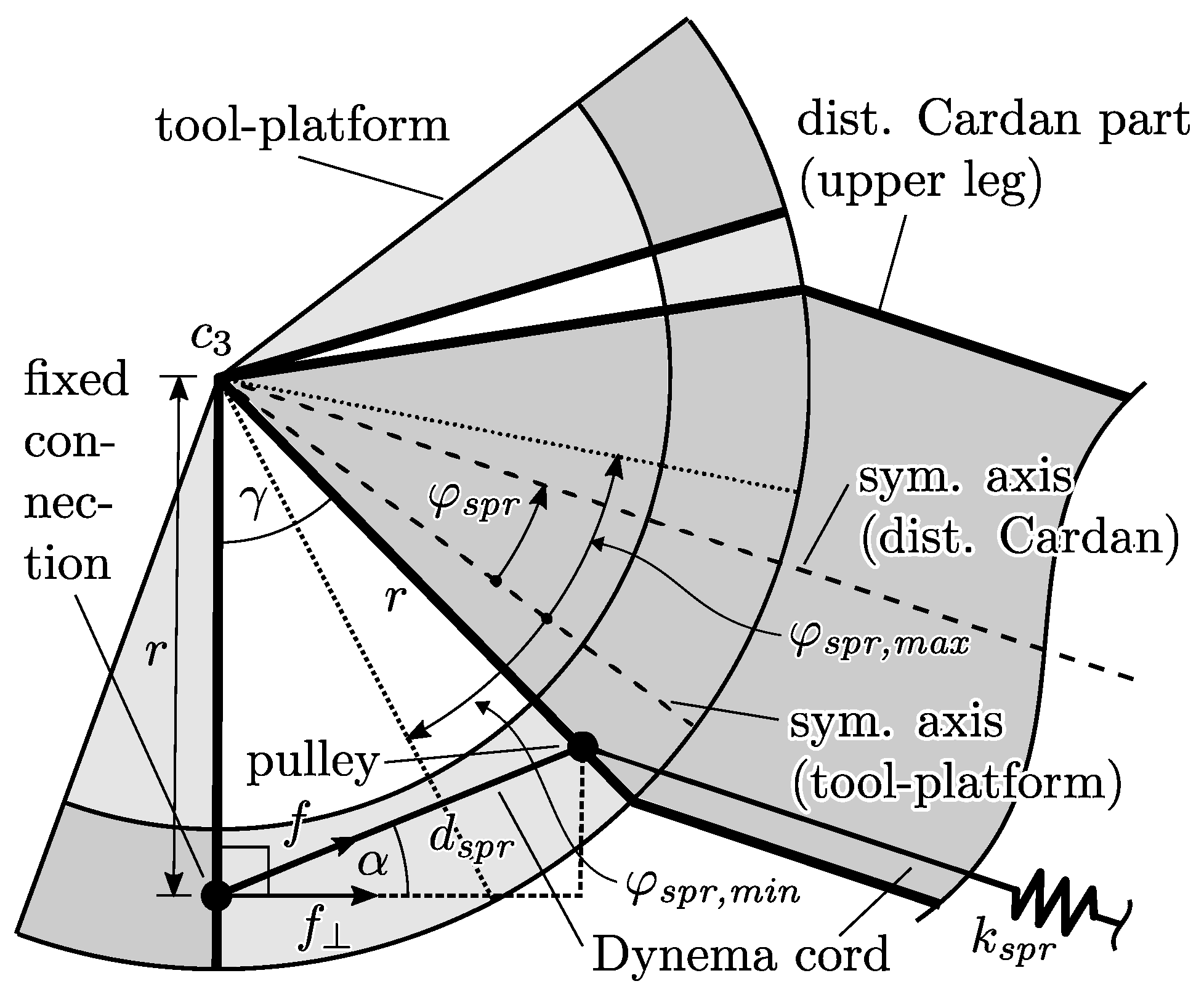
Figure 21.
Geometry of the spring mechanism. The tool-platform and distal Cardan part are anchored at axis vertical to the paper plane, crossing the centre of the spherical parallel manipulator.
Figure 21.
Geometry of the spring mechanism. The tool-platform and distal Cardan part are anchored at axis vertical to the paper plane, crossing the centre of the spherical parallel manipulator.
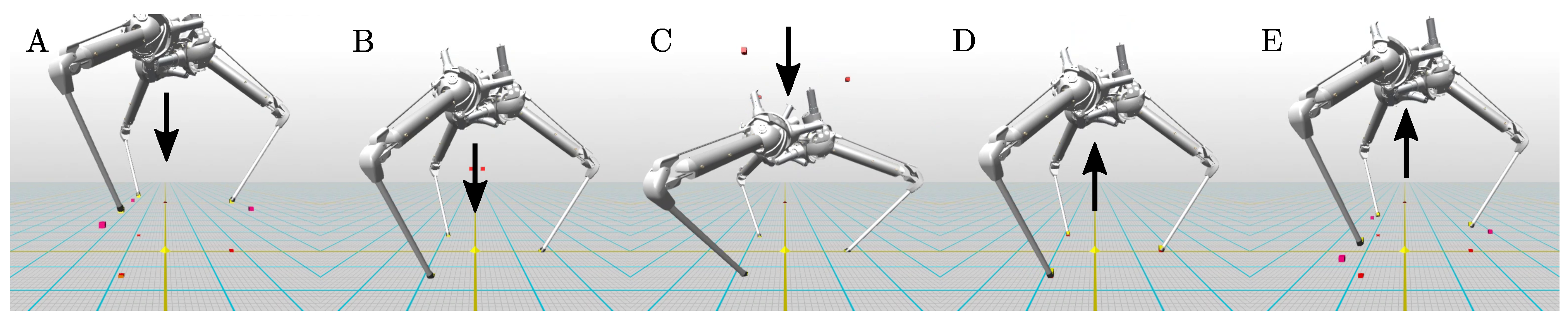
Figure 22.
Drop test simulation states A–E of the compliant robot configuration in chronological order captured from the simulation framework and motion vector of the torso, depicting Setup A.
Figure 22.
Drop test simulation states A–E of the compliant robot configuration in chronological order captured from the simulation framework and motion vector of the torso, depicting Setup A.
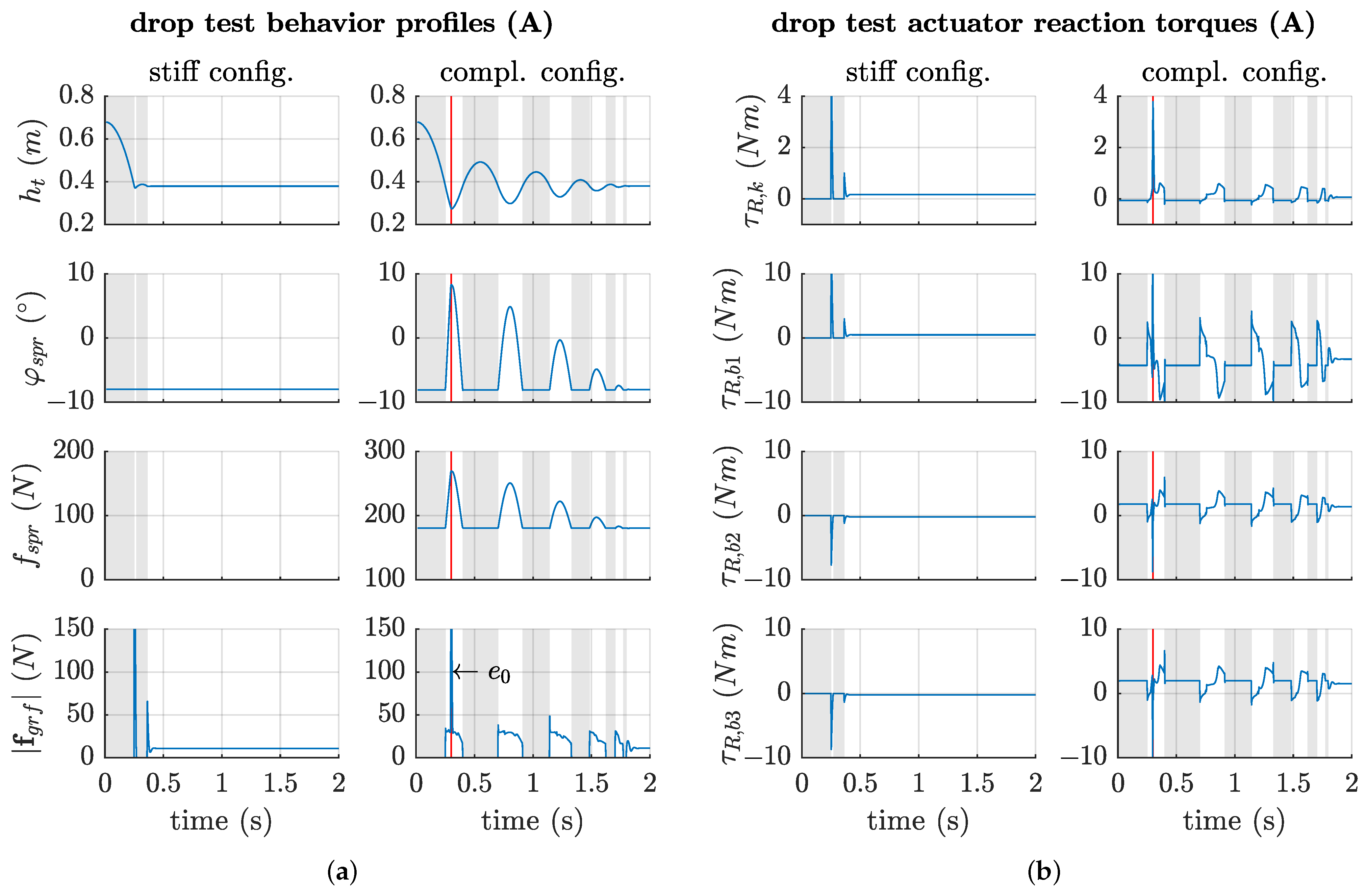
Figure 23.
(a) Free-fall simulation profiles of Setup A of the robot model for both stiff and compliant configurations. The red line shows the time of the internal collision. The grey background visualises states of no contact between the robot feet and the ground. (b) Reaction torques of the fixed actuator axis of one leg, captured from the drop simulation of Setup A for both stiff and compliant configurations. Internal collisions occur at the red line.
Figure 24.
Characteristic profiles from the drop experiment Setup B, only depicting the compliant robot configuration. The base joints plots are scaled equally for comparison reasons.
Figure 24.
Characteristic profiles from the drop experiment Setup B, only depicting the compliant robot configuration. The base joints plots are scaled equally for comparison reasons.
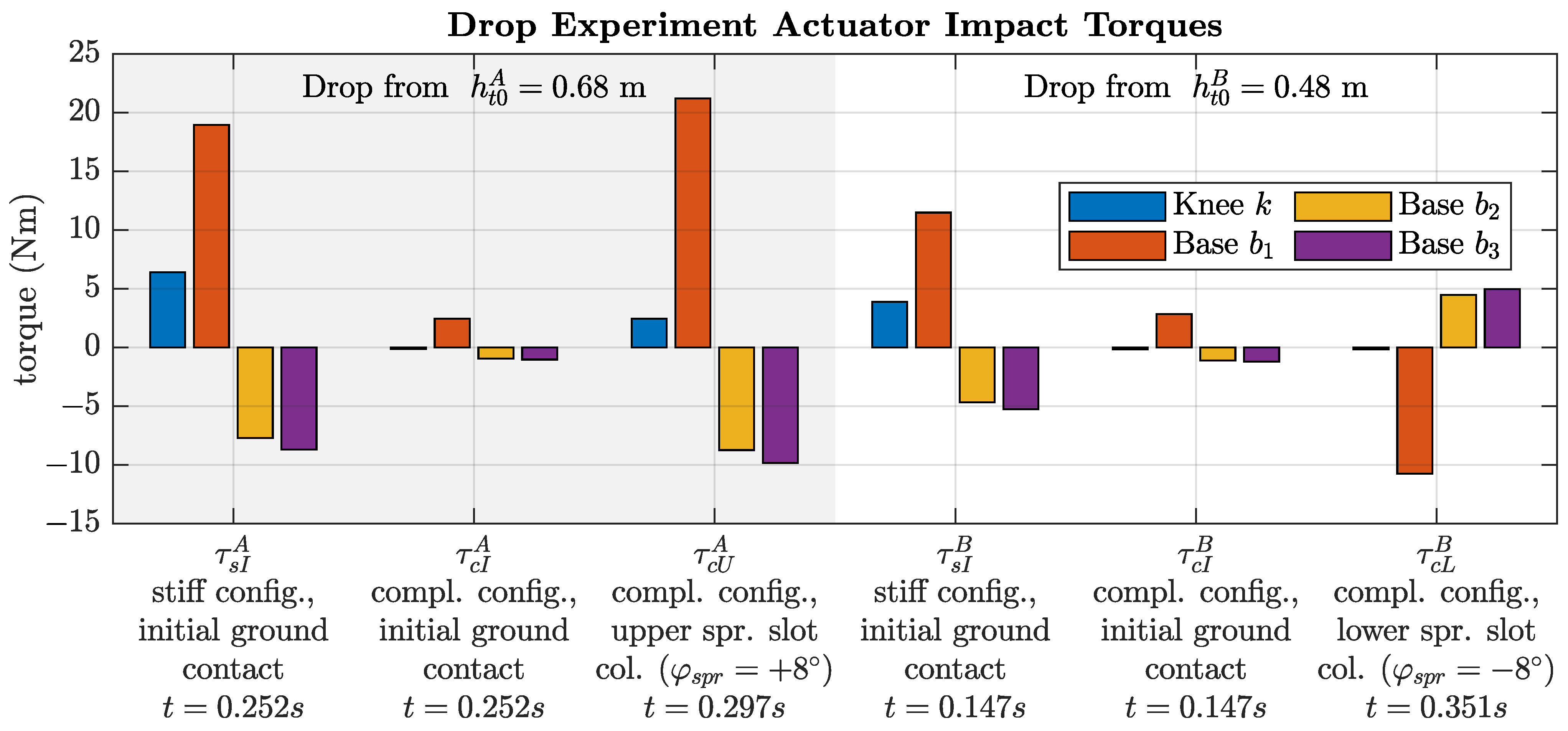
Figure 25.
Impact torques for both Experiment Setups A and B exerted in the four actuator axes due to different events, e.g., ground impacts or internal spring slot collisions. The last row depicts the points in time of the individual events, which thus can be picked up individually in
Figure 23b and
Figure 24.
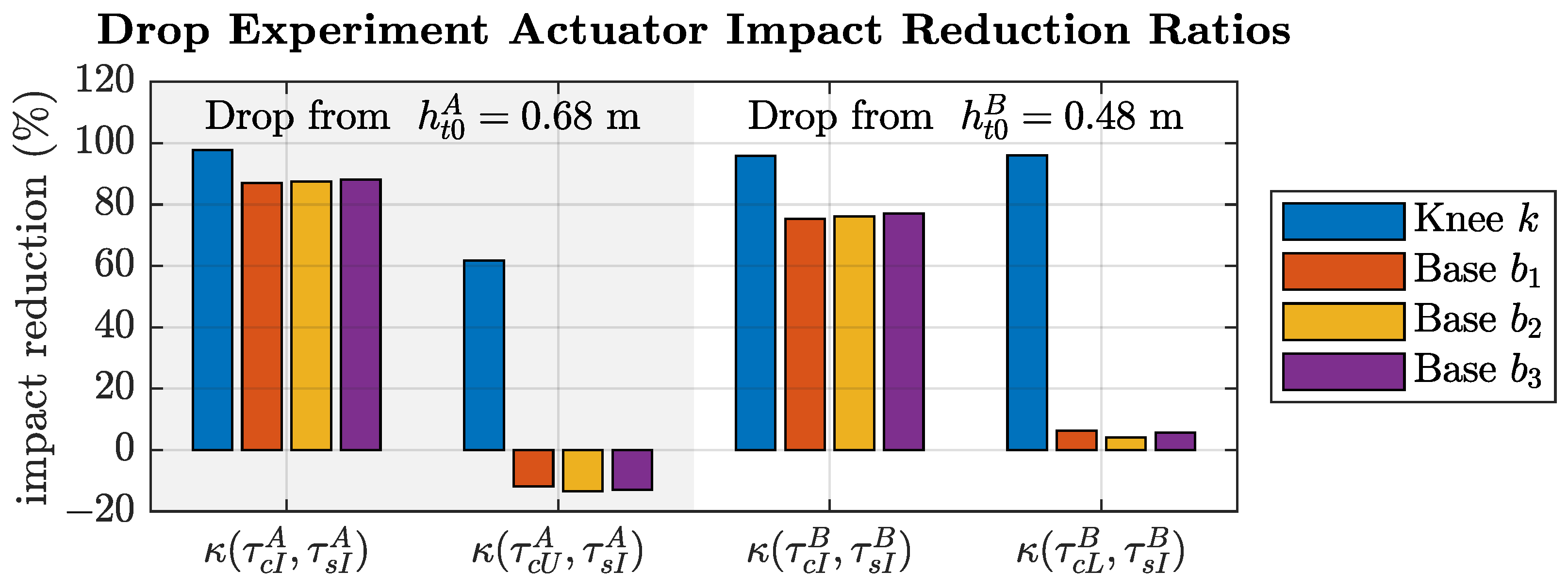
Figure 26.
Impact reduction ratio between the stiff and compliant configuration for each actuator. Higher percentages correspond to a better impact reduction.
Figure 26.
Impact reduction ratio between the stiff and compliant configuration for each actuator. Higher percentages correspond to a better impact reduction.
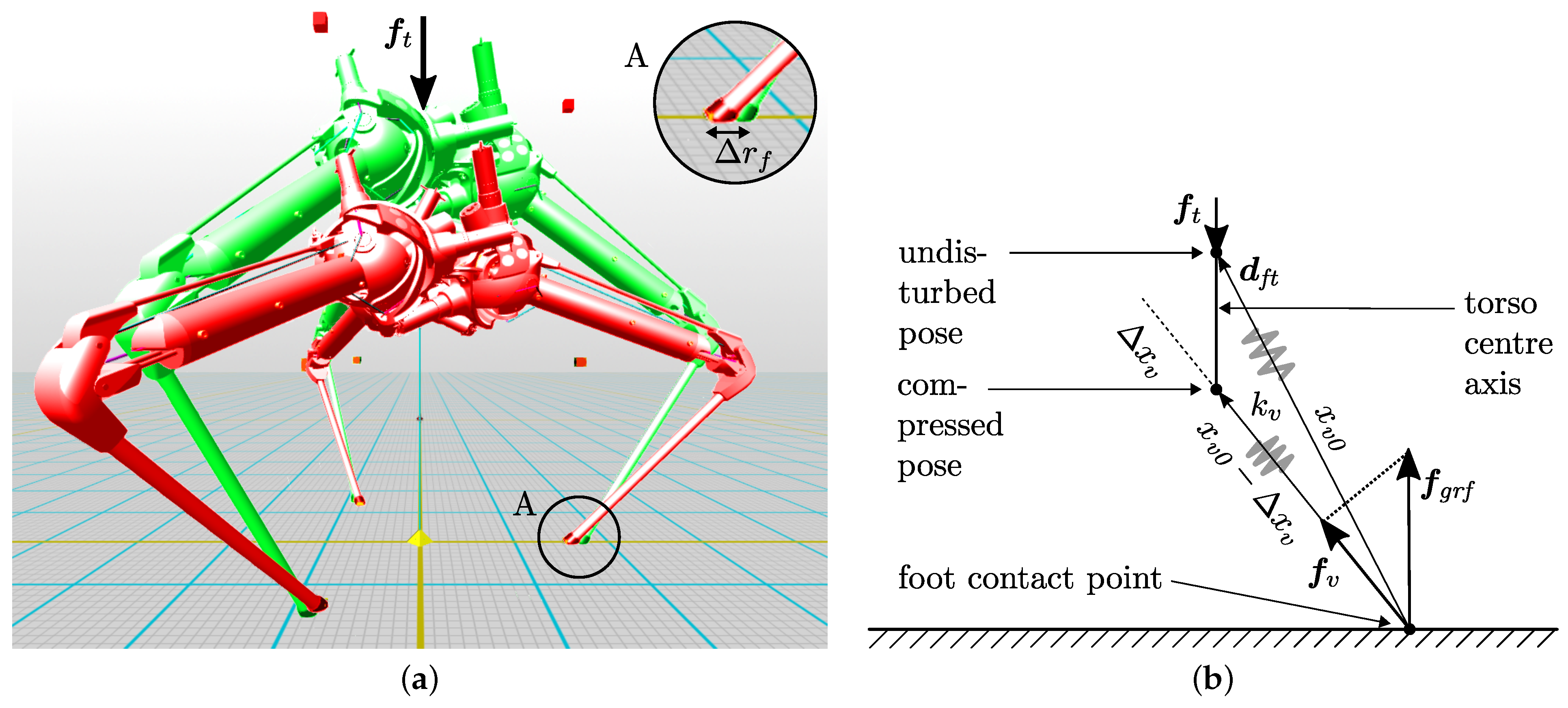
Figure 27.
(a) Setup for the virtual spring stiffness measurement. Green shows the undisturbed pose, red the compressed pose after exerting force . In Detail A, the constraint foot displacement is shown. (b) Geometric representation of the virtual spring between undisturbed and maximal compressed robot pose.
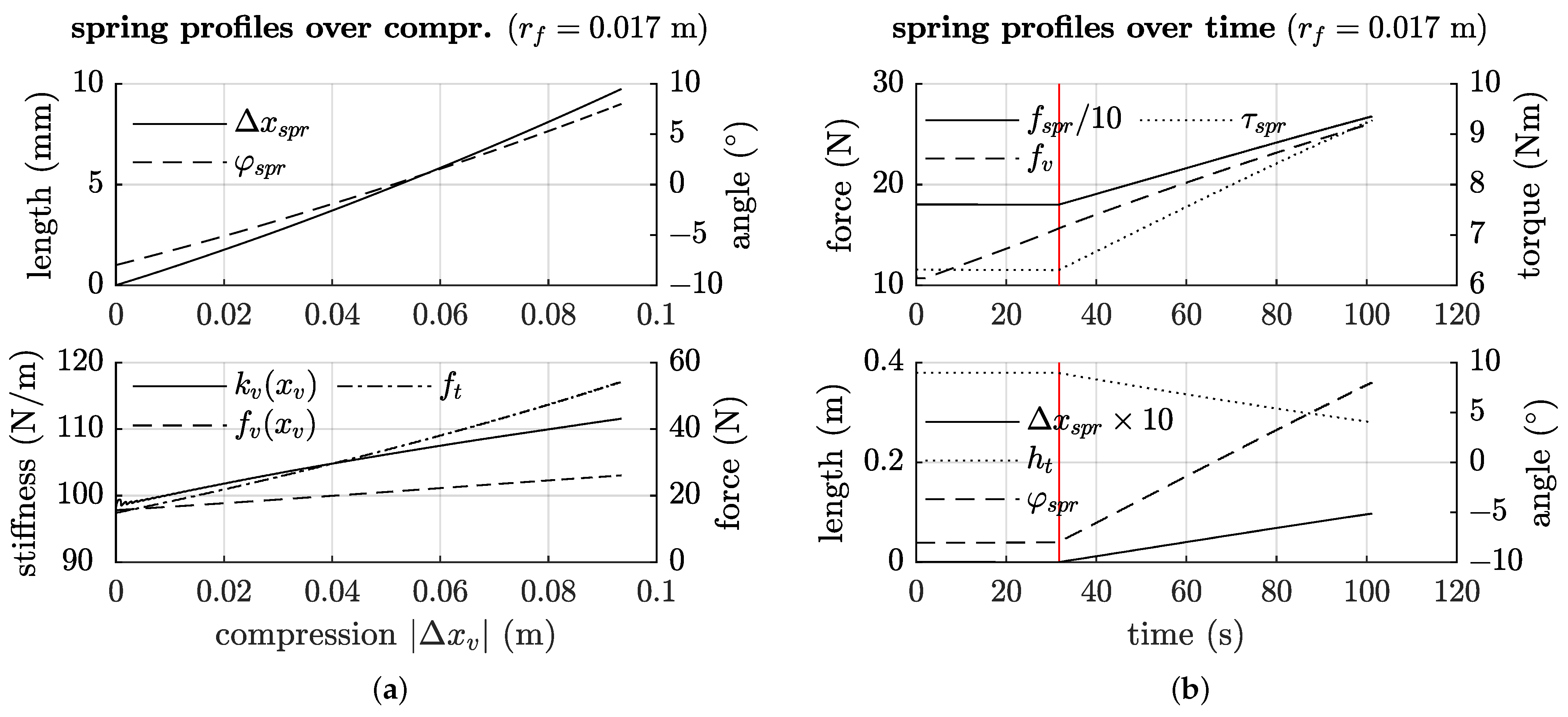
Figure 28.
(a) Measurements of the characteristic values over the virtual compression . The upper plot is related to the internal spring behaviour, the lower plot to the resulting virtual spring. (b) Profiles over time, which shows the required build-up of forces before the robot starts to alter its pose. The red line marks the point of transition.
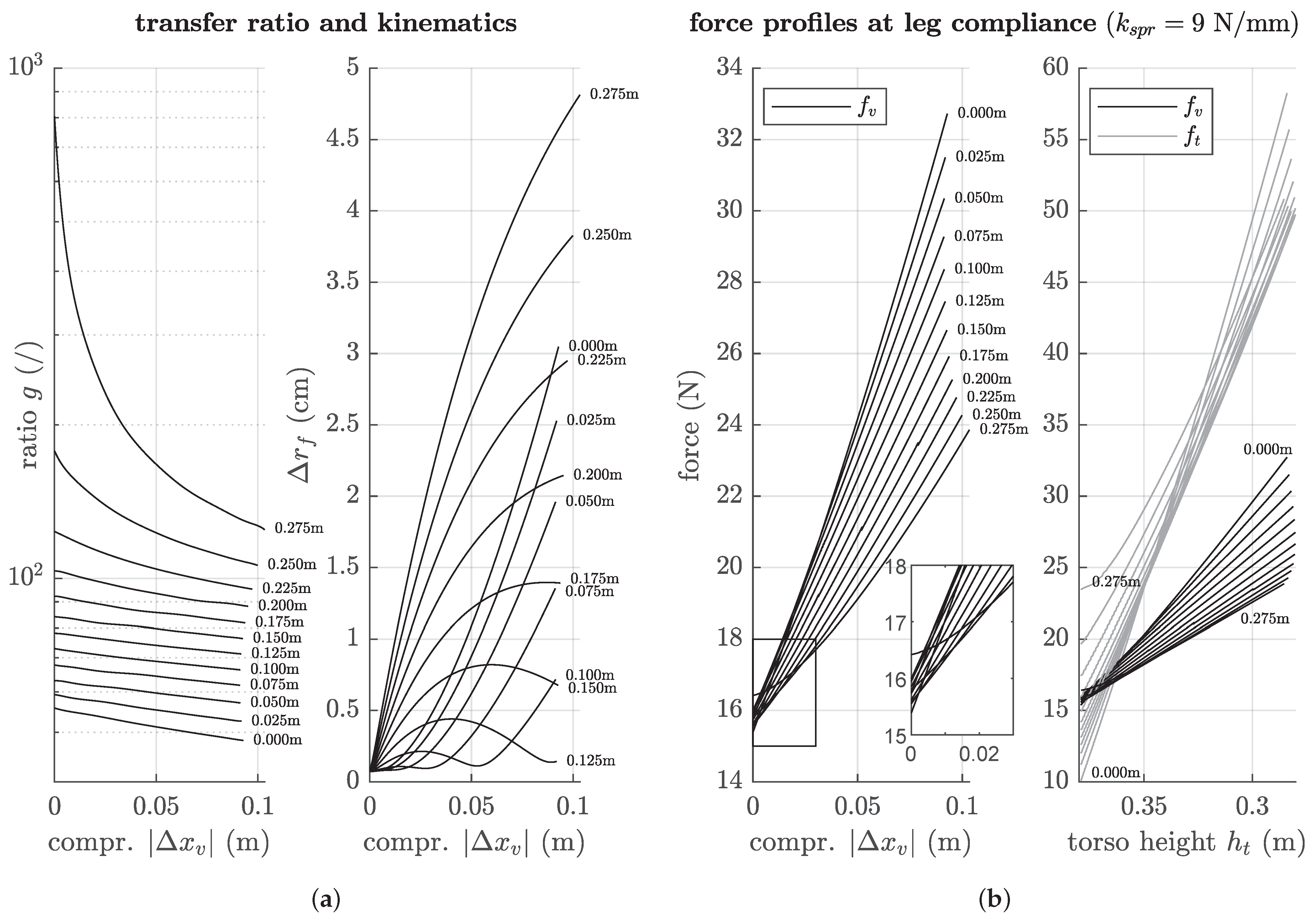
Figure 29.
(a) Transfer ratio g and corresponding foot displacement over the virtual leg compression . Text annotations on the graphs depict the initial foot radius of the specific setup. (b) Force profiles during the push down phase regarding the virtual compression and the geometrical torso height. Text annotations in the plot on the right side mark only the first and last element with steps of m between neighbouring graphs.
Figure 30.
Experiment setup. The prototype leg is attached to a camera tripod, which prevents collisions with the environment during motion. An attachment plate connects the tripod and centre tray.
Figure 30.
Experiment setup. The prototype leg is attached to a camera tripod, which prevents collisions with the environment during motion. An attachment plate connects the tripod and centre tray.
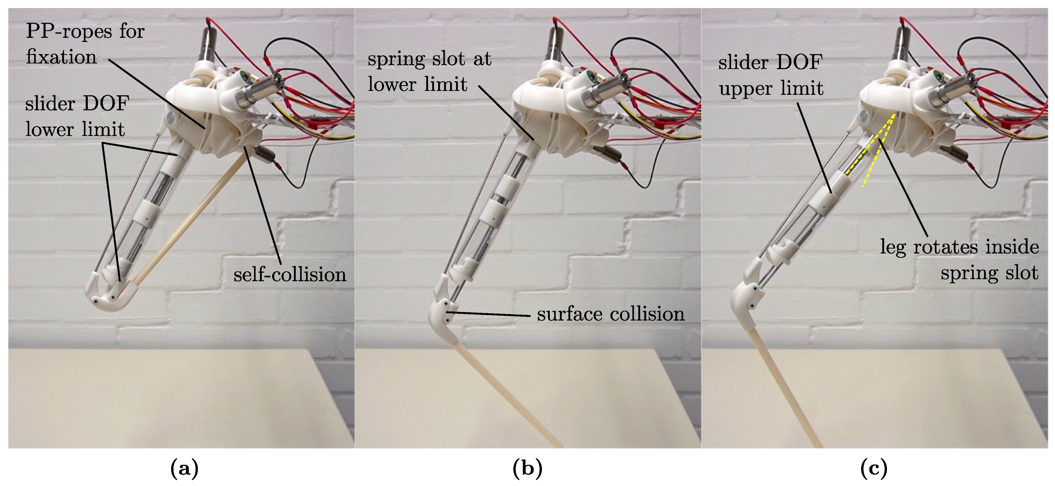
Figure 31.
Characteristic poses of the leg mechanism. (a) Full retracted pose, with the slider at its lowest position. (b) Surface collision between two parts of the four-bar linkage. (c) Additional motion capability of the leg for further extension. The slider is at its max. position, pushing against the internal spring forces, while the leg rotates upwards inside the spring slot.
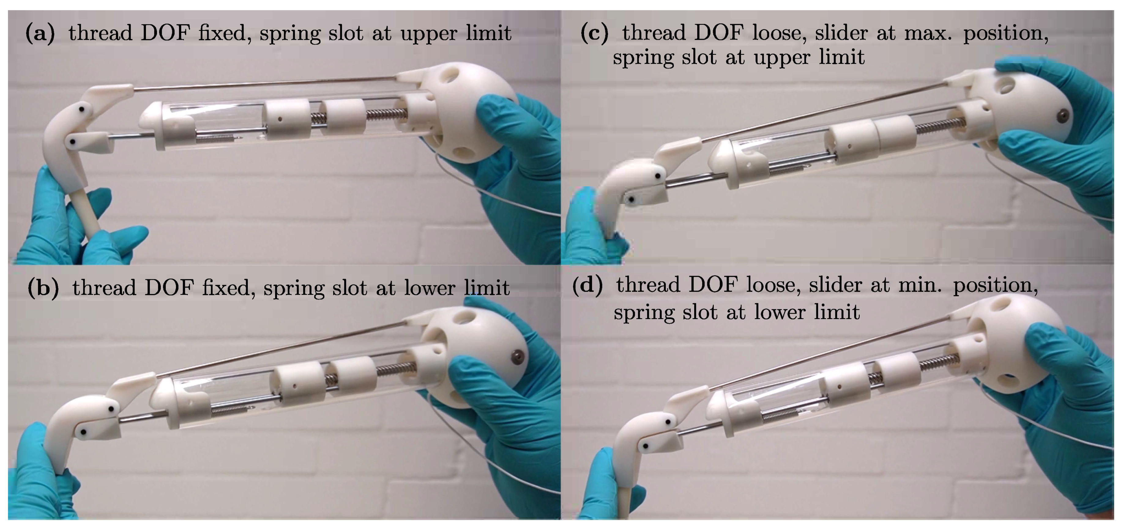
Figure 32.
(a,b) depict the spring slot motion with a fixed thread DOF, thus fixing the position of the slider. In (c,d) the slider and lower leg are kept fixed relative to each other. Any further slider motion requires the additional motion of the spring slot DOF that also acts against the internal spring.
Table 1.
Overview of the goals, design foundations, and methods for the legged robot.
Table 1.
Overview of the goals, design foundations, and methods for the legged robot.
| Project Goals | Required Design Foundations | Selected Design Methods |
|---|
Agile, highly dynamic, and compact legged robot. Ability to perform locomotion over flat and irregular terrain. Statically stable pose for additionally performed secondary tasks. Dynamically balanced, energy-efficient dynamics during locomotion.
| Approximation of the SLIP model. Dense mass concentration in the torso centre. Leg structures with low mass and inertia. Integrated leg compliance for storing and releasing energy. Low total mass of the structural mechanism and actuators.
| The SPM as the hip joint for agile motion with central universal joint as the load-support structure. Interlocking actuator arrangement for a dense mass concentration and compact robot size, with all 12 actuators placed inside the torso. Leg compliance via a 4 bar closed-loop linkage, located in series with the actuators. Three legs as a requirement for statically stable standing. Intricate, complex shapes for densely interconnected structural parts via 3D printing. Composite material design, light parts, and stiff structure.
|
Table 2.
Z-X-Z Euler angles in degree (
) of the individual rotation matrices
, expressing the relationship between the hip centre frames (hip base,
hb) and the torso body reference frame (end-effector,
ee) for the refined robot model. The orientation between the base-platform frame (
hb) and the tool-platform frame (hip follower,
hf) is expressed by
and is identical for each leg.
Figure 4a,b shows the visual representation of the data.
| Axis | | | | |
|---|
| 112 | −128 | −8 | 101.006 |
| 115 | 115 | 115 | 7.479 |
| 0 | 0 | 0 | −104.288 |
Table 3.
Vector components of the actuator axis vectors , expressed in the hip base frame (hb), identical for each leg. Hat-notation refers to vectors of unit-length.
Table 3.
Vector components of the actuator axis vectors , expressed in the hip base frame (hb), identical for each leg. Hat-notation refers to vectors of unit-length.
| Actuator Axis j | | | |
| | 0 | |
| | | |
| | | |
Table 4.
Physical properties and mass distribution of the robot model with N representing the number of repeated parts. The data were derived from the CAD model. Entries are ordered by function.
Table 4.
Physical properties and mass distribution of the robot model with N representing the number of repeated parts. The data were derived from the CAD model. Entries are ordered by function.
| Assembly | Variable | N | Mass m (g) | (%) |
| (Torso) centre tray | | 1 | 47.993 | 1.45 |
| (SPM) base-platform | | 3 | 478.649 | 43.26 |
| (SPM) tool-platform | | 3 | 56.411 | 5.10 |
| (SPM) proximal link | | 9 | 25.606 | 6.94 |
| (SPM) distal link | | 9 | 12.417 | 3.37 |
| (Support) prox. Cardan part | | 3 | 121.475 | 10.98 |
| (Support) Cardan cross-ring | | 3 | 20.551 | 1.86 |
| (Support) distal Cardan part | | 3 | 117.734 | 10.64 |
| (CV) prox. transmission axis | | 3 | 20.168 | 1.82 |
| (CV) mid. transmission axis | | 3 | 1.000 | 0.09 |
| (CV) dist. transmission axis | | 3 | 43.348 | 3.92 |
| (CV) inner CV ring ball cage | | 6 | 4.000 | 0.72 |
| (Leg) slider structure | | 3 | 36.432 | 3.29 |
| (Leg) support axis | | 3 | 25.276 | 2.28 |
| (Leg) lower leg | | 3 | 47.363 | 4.28 |
| Torso assembly | | 1 | 2214.476 | 66.71 |
| Leg assembly | | 3 | 368.315 | 11.10 |
| Build prototype (CAD) | | 1 | 1138.469 | - |
| Build prototype (real) | | 1 | (measured) 1156.6 ± 0.5 | - |
| Robot assembly | | 1 | 3319.421 | 100.00 |
Table 5.
Geometrical properties of the robot model and default values. Variables are depicted in the CAD model in
Figure 20a.
Table 5.
Geometrical properties of the robot model and default values. Variables are depicted in the CAD model in
Figure 20a.
| Parameter | Variable | Value | Unit |
|---|
| Hip radius | | | m |
| Foot radius | | | m |
| Torso height | | | m |
| Upper leg length | | | m |
| Lower leg length | | | m |
| Robot COM height | | 0.371 | m |
Table 6.
Characteristic drop test states of
Figure 22.
Table 6.
Characteristic drop test states of
Figure 22.
| # | State Description | (m) | Time t (s) |
| A | Release, free-fall | 0.680 | 0.000 |
| B | Ground contact | 0.376 | 0.252 |
| C | Max. spring deflection | 0.275 | 0.300 |
| D | Spring contraction | 0.381 | 0.399 |
| E | Apex after lift-off | 0.492 | 0.549 |
Table 7.
Characteristic modelling parameters, used for the drop test simulation.
Table 7.
Characteristic modelling parameters, used for the drop test simulation.
| Parameter | Variable | Value | Unit |
|---|
| Floor contact stiffness | | 20,000 | N/m |
| Floor contact damping | | 200 | N s/m |
| Contact static friction | | 0.8 | − |
| Contact dynamic friction | | 0.7 | − |
| Simulation step time | | | s |
| Simulink solver | - | ode2 (Heun) | − |
| Joint limit stiffness | | 12,000 | Nm/rad |
| Joint limit damping | | 30 | Nm s/rad |
| Joint friction coefficient | | 0.01 | − |
| Joint friction damping | | | Nm s/rad |
| Torso height | | 0.68 | m |
| Torso height | | 0.48 | m |
| Fall distance | | 0.30 | m |
| Fall distance | | 0.10 | m |
| Spring stiffness | | 9 | N/mm |
| Initial spring deflection | | 0.020 | m |
Table 8.
Actuator torques necessary to keep the robot in a static standing pose and resulting joint loads, not accounting for the possible real-world stick–slip effects of the robot joints.
Table 8.
Actuator torques necessary to keep the robot in a static standing pose and resulting joint loads, not accounting for the possible real-world stick–slip effects of the robot joints.
| Parameter | (mNm) | (mNm) | (mNm) | (mNm) |
| Value | 151 | 425 | | |
Table 9.
Notation for different cases, respectively events, of the drop test experiment.
Table 9.
Notation for different cases, respectively events, of the drop test experiment.
| Torque | Description |
|---|
| Compliant robot configuration |
| Stiff robot configuration |
| Initial foot–ground contact |
| Upper spring slot collision () |
| Lower spring slot collision () |
Table 10.
Push down experiment parameters, depicting the initial default robot pose at the transition from the static pose at to beginning compression.
Table 10.
Push down experiment parameters, depicting the initial default robot pose at the transition from the static pose at to beginning compression.
| Parameter | Value | Unit |
|---|
| Default ground reaction force | | N |
| Initial spring threshold | | N |
| Max. torso height | | m |
| Min. torso height | | m |
| Initial foot radius | | m |
| Max. horizontal foot displacement | | m |
Table 11.
Fitting quality of the polynomial curves for ratio
g, depicted in
Figure 29a.
Table 11.
Fitting quality of the polynomial curves for ratio
g, depicted in
Figure 29a.
| Parameter | Data |
|---|
| (m) | 0.000 | 0.025 | 0.050 | 0.075 | 0.100 | 0.125 | 0.150 | 0.175 | 0.200 | 0.225 | 0.250 | 0.275 |
| RMSE () | 6.24 | 7.16 | 8.40 | 8.90 | 28.87 | 4.06 | 11.68 | 13.38 | 10.95 | 5.26 | 17.36 | 46.30 |
| () | 99.98 | 99.96 | 99.92 | 99.88 | 98.85 | 99.98 | 99.82 | 99.84 | 99.94 | 99.99 | 99.98 | 99.97 |
Table 12.
Summary of the main results and properties of the robot discovered in this work.
Table 12.
Summary of the main results and properties of the robot discovered in this work.
| Resulting Robot Properties |
|---|
Combined serial–parallel 4-DOF actuation scheme per leg. Radially symmetrical, omnidirectional layout. High load carrying capacity of the central support joint, reducing stress on the SPM linkages. Redundant leg kinematics, possibly allowing for optimised actuator load and agility.
| Lightweight, compact, and dense mechanical model with a non-overconstrained topology. Possible hybrid compliant behaviour, with the threshold value gating stiff from the compliant state. Reasonable linear resulting spring profile of the robot model. Feasibility of the mechanical system shown via the real-world model.
|


