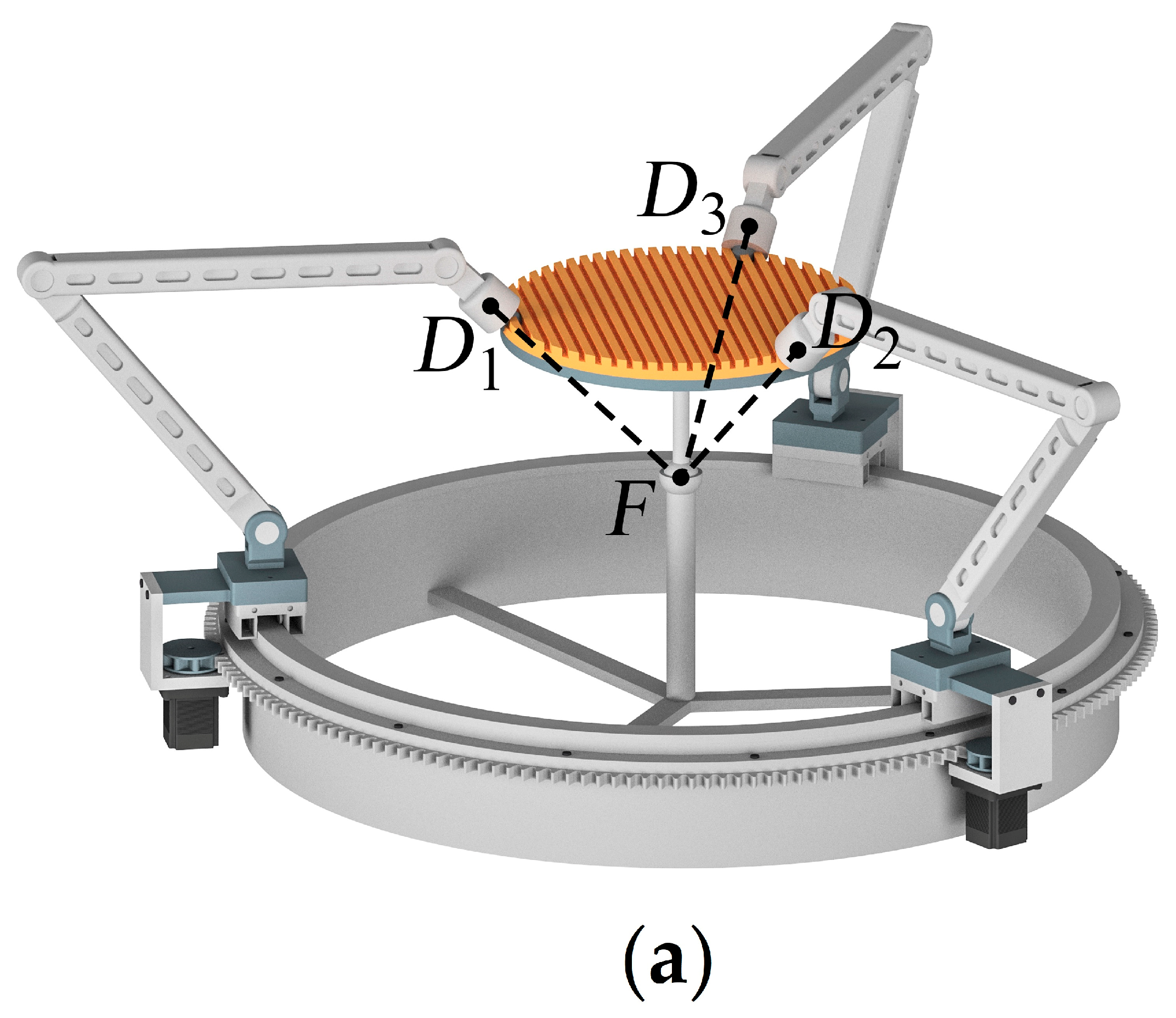
1. Introduction
For survivors of COVID-19, defeating the virus is only the beginning of the road to recovery. COVID-19 causes a number of coexisting diseases that require rehabilitation [
1,
2]. In this way, the automation of medical equipment plays a significant role. Most of this equipment is created on the structures of parallel mechanisms. They represent mechanical systems in which the output link connects to the base with several kinematic chains. Such structure provides these mechanisms with advanced functional properties, which cause their usage in diverse applications [
3,
4,
5].
Amongst various applications, parallel mechanisms are highly demanded in medicine. Currently, the development of such systems and their adaptation for medical applications have become even more crucial when new infections and viruses appear, including COVID-19—we need modern and effective medical equipment to resist these infections and for rehabilitation after the diseases.
There are many examples of parallel mechanisms used for rehabilitation. For example, paper [
6] proposed a mechanism with two degrees of freedom (DOFs) for ankle rehabilitation. The mechanism includes 3-SPU/1-U kinematic chains: the 1-U chain constrains the output link motion and leaves it two rotational DOFs. Work [
7] presented another mechanism for ankle rehabilitation. It has 3-RUS/RRR kinematic chains, and the RRR chain provides the output link with spherical motion. Study [
8] considered a cable-driven mechanism for waist rehabilitation. This mechanism reproduces required frontal and lateral bends and rotation around the vertical axis. Work [
9] showed another cable-driven mechanism used for upper-limb rehabilitation. The authors of [
10] proposed a mechanism for lower-limb rehabilitation. The mechanism includes hip-knee and ankle modules, which allow it to perform hip flexion/extension, knee flexion, plantar flexion/dorsiflexion, and ankle eversion/inversion. Paper [
11] presented a 4-DOF 2RPRR-2UPS mechanism for knee rehabilitation; its output link can perform planar motion and additional rotation. Work [
12] considered a 9-DOF hybrid (parallel-serial) mechanism for foot rehabilitation. This mechanism has two vertical modules: the lower module has six DOFs, the upper—three DOFs.
Besides rehabilitation, parallel mechanisms are also used for surgical operations, especially minimally invasive surgery. For example, paper [
13] introduced the hybrid mechanism PARASURG9M, which includes two modules: 5-DOF surgical robotic arm PARASURG5M and 4-DOF robotized surgical instrument PARASIM, based on a 3-RRR spherical mechanism. Study [
14] considered another hybrid mechanism PRAMiSS; its parallel module is followed by an RPRR serial mechanism with a laparoscopic tool. The authors of [
15] presented a 3-DOF mechanism with 2-SPS and 1 RRR kinematic chains, in which the 1-RRR chain provides the output link with spherical motion. A laparoscopic tool can translate relative to the output link and has a stationary center of motion. Paper [
16] proposed a similar mechanism that has 1-RRRP and 2-RRRUR kinematic chains. The 1-RRRP chain provides spherical motion and includes a motor that controls tool translation. Work [
17] demonstrated another spherical mechanism with 2-RPR and 1-PR chains. A similar design with two RRR chains is given in [
18] and with spherical rails in [
19].
There are also parallel mechanisms used for other medical applications. The authors of [
20] suggested using a parallel mechanism in a knee joint to provide femur displacement relative to the tibia. Study [
21] presented a 6-DOF mechanism for arterial examinations. The mechanism includes two chains with planar five-bar linkages and has an elongated workspace along the horizontal direction; the mechanism design allows it to scan all human arteries. Paper [
22] considered implementing a symmetrical 3-RRR spherical mechanism for tele-echography applications.
The review above shows that medical applications often require mechanisms with a spherical motion pattern. In this regard, many medical robots and manipulators are based on spherical mechanisms. These mechanisms include a class of systems with a circular rail, which output link can perform unlimited rotations around one axis [
23,
24,
25,
26,
27,
28]. Despite several advantages, such mechanisms, however, provide a fixed center of spherical motion.
The fixed location of this spherical motion center can be impractical in some applications. Therefore, designing a reconfigurable mechanism that could displace this center and, hence, vary the workspace parameters and expand the mechanism capabilities seems promising. The authors of the current study found only one such mechanism [
29], which includes an additional screw-like kinematic chain used for the reconfiguration. This chain, however, is coupled with other chains: such a design limits the distance at which the spherical motion center can move.
The current article aims at developing a reconfigurable spherical mechanism that can change the location of the spherical motion center and has a fourth kinematic chain uncoupled to other chains. The paper has the following organization.
Section 2 introduces an original spherical mechanism proposed by the authors in [
26] and used as a basic mechanism.
Section 3, the core of the study, presents several reconfigurable modifications of the original mechanism. Both sections apply screw calculus to verify the motion pattern of each mechanism.
Section 4 recaps the entire study and mentions directions for future research.
2. Original Mechanism
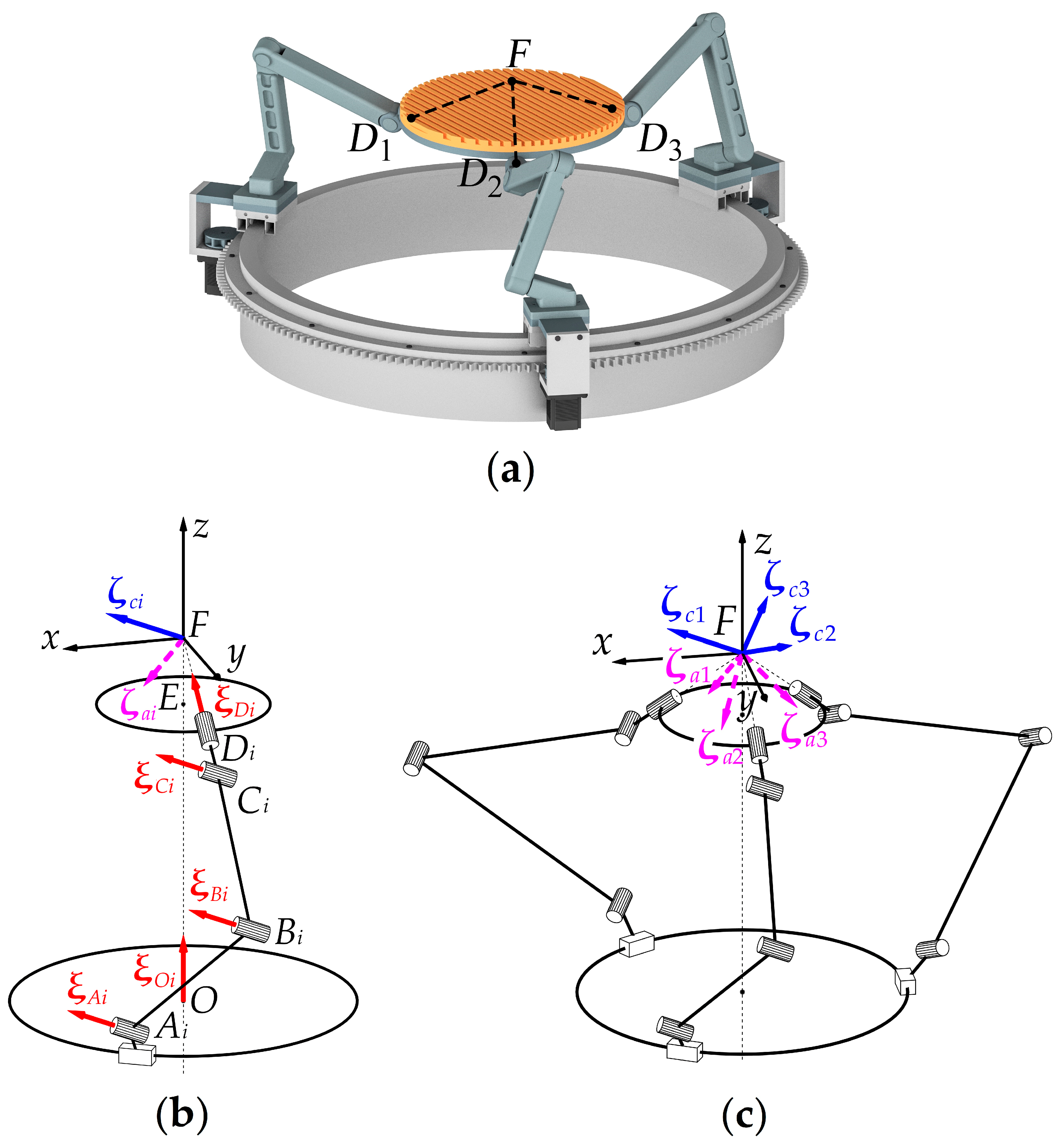
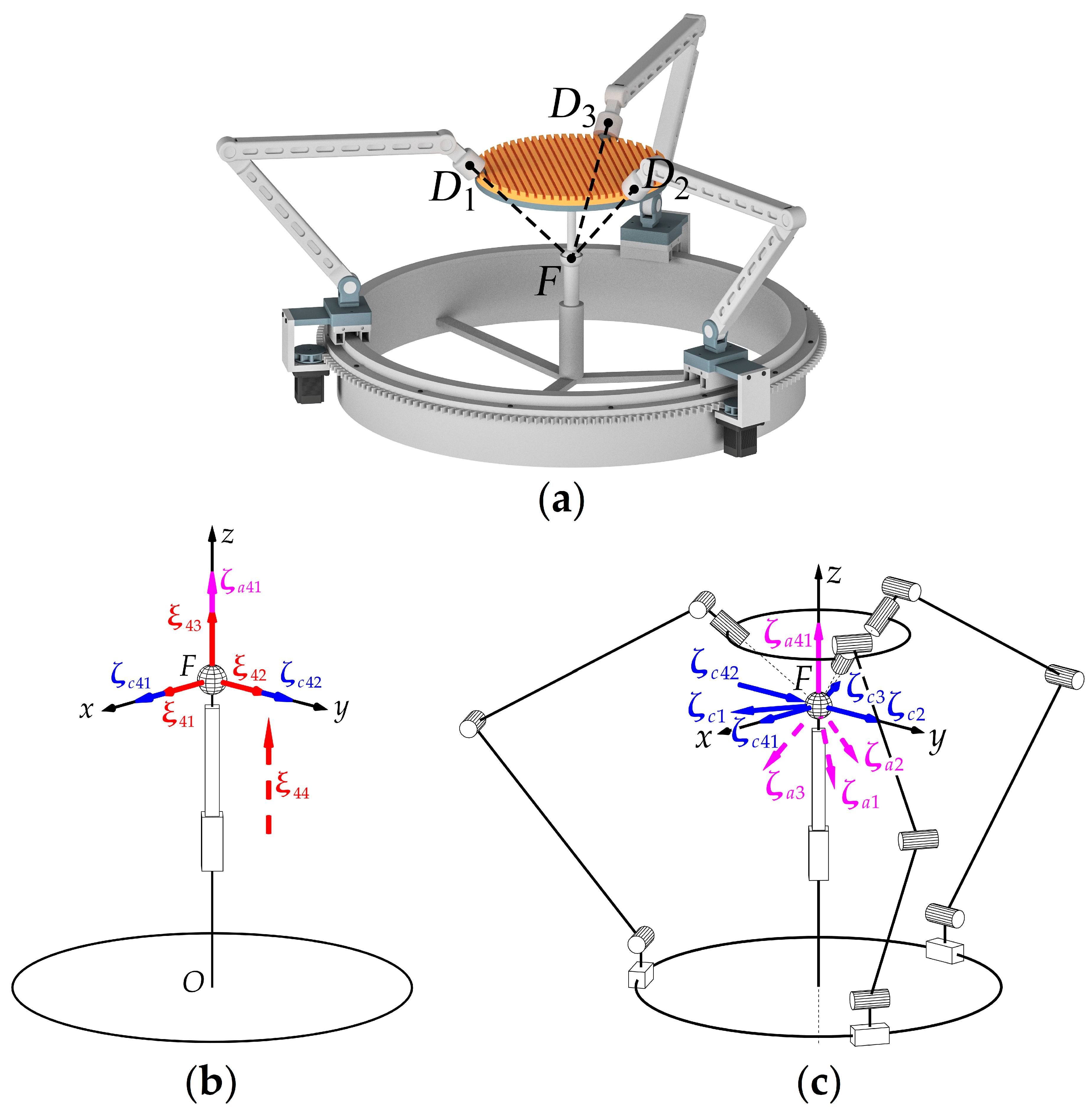
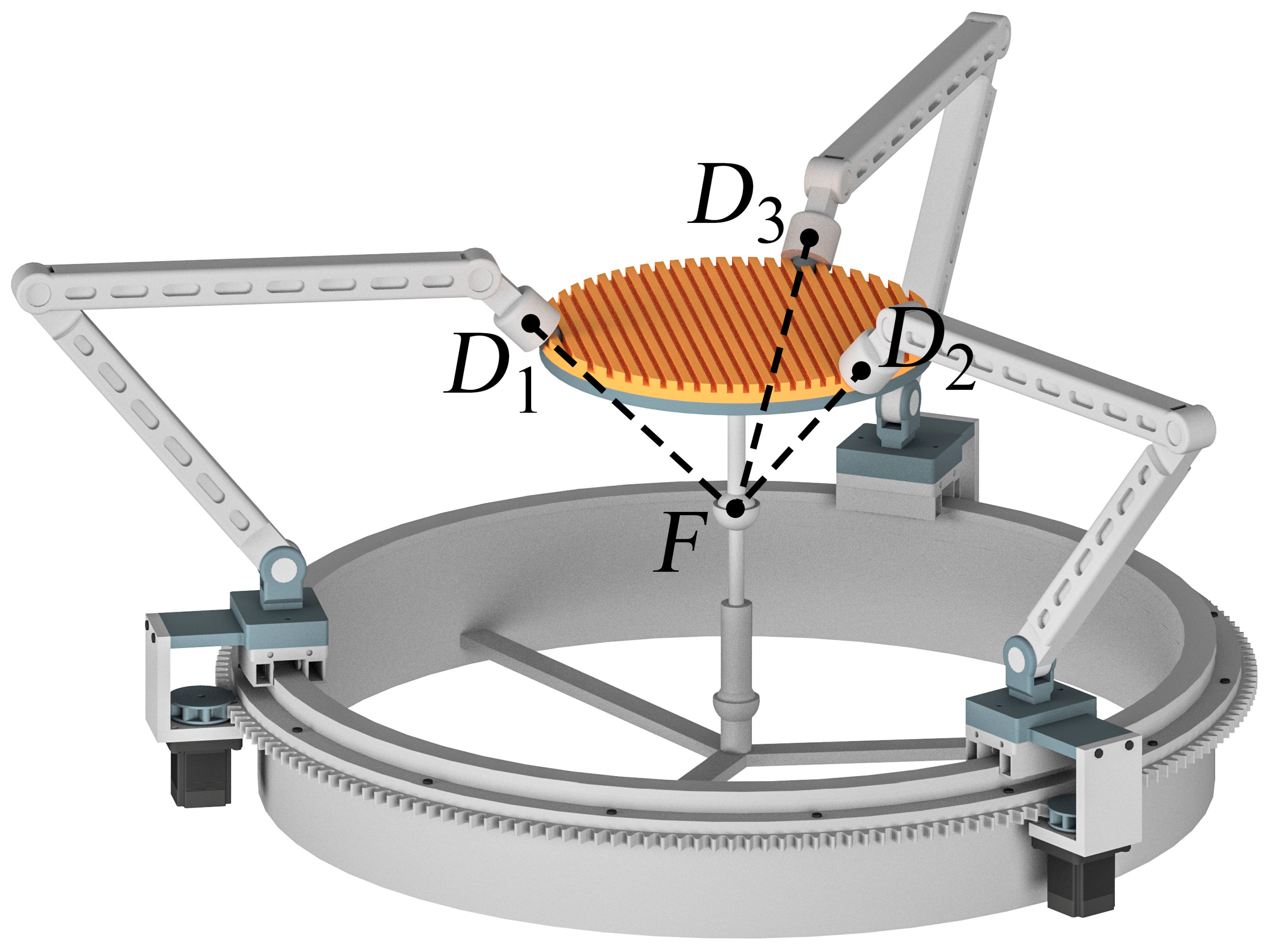
Figure 1a presents the original spherical mechanism proposed in [
26]. The mechanism consists of three identical kinematic chains (legs) that connect an output link (moving plate) with a base. Let
be an index number of a kinematic chain and consider the
-th chain. The chain includes five revolute kinematic pairs (joints), where the first joint (point
O) is actuated and realized as a carriage moving along a circular rail (
Figure 1b). The axes of three intermediate joints (points
Ai,
Bi, and
Ci) are parallel to each other and orthogonal to a plane, tilted to the circular rail plane by a certain angle; this angle remains the same for any chain configuration. The axis of the fifth joint (point
Di), attached to the moving plate, intersects the axis of the first joint at point
Fi; this intersection is also preserved for any chain configuration. Note that point
Fi does not necessarily lie on the moving plate itself, i.e.,
EFi ≠ 0, where point
E corresponds to the moving plate center. Finally, by the mechanism design, the axes of the moving plate joints intersect at common point
F, i.e., points
Fi coincide for all three kinematic chains.
To verify that the mechanism has a spherical motion type, we will apply a common approach based on screw calculus [
30]. Since the mechanism has three identical kinematic chains, we can start with an analysis for one chain and then deduce the results for the entire mechanism.
Let us introduce some additional notations first. Without loss of generality, we assume the axis of the first joint is vertical and coincides with the
Fz axis of the reference frame
Fxyz (
Figure 1b). Directions of axes
Fx and
Fy can be chosen arbitrarily. Given these notations, we can write a plate twist system for one kinematic chain in frame
Fxyz:
where (unit) twists
,
,
,
, and
correspond to rotations in the chain joints;
is a unit vector directed along the axis of the first joint;
is a unit vector directed along the axis of the fifth joint;
,
, and
are vectors from point
F to points
Ai,
Bi, and
Ci, respectively.
In Equation (1), we have written screw coordinates in a ray order [
31]: the first three components represent the vector part, the last three—the moment part. We will use this order for all other twists and wrenches throughout the paper. Note that twists
,
, and
have the same vector part,
, because the axes of joints
Ai,
Bi, and
Ci are parallel to each other.
One can see vectors , , and are linearly independent in a general (non-singular) configuration of the chain. Therefore, the mechanism moving plate will have three rotational DOFs, with point F being the pivot point. Translational DOFs, on the other hand, correspond to the nonzero moment parts of the joint twists. Three cross products in (1) are linearly dependent: all of them include vector and all vectors perpendicular to lie in parallel planes. Therefore, the moving plate will have two translational DOFs in a plane that contains points Ai, Bi, and Ci.
Since the leg provides the moving plate with five DOFs, it should impose one constraint on the plate motion. We can find corresponding constraint wrench
, reciprocal to twists (1), by simple inspection [
32]:
This wrench corresponds to a force constraining the plate translation along direction
. Three kinematic chains of the mechanism will impose three constraint wrenches (2) on the moving plate. In a non-singular configuration, these wrenches span a three-dimensional constraint space, preventing any translational motion of the moving plate (
Figure 1c). Thus, the mechanism is spherical.
Let us also examine the situation when the carriage is stopped. In this case, we can find actuation wrench
, reciprocal to all twists (1) except for
and independent of constraint wrench
:
The actuation wrench above relates to a couple that the carriage transmits to the moving plate. Two other chains provide similar actuation wrenches (
Figure 1c). The mechanism will work correctly when three constraint wrenches
and three actuation wrenches
are linearly independent—this is the general case for the considered mechanism. Configurations in which these wrenches become linearly dependent represent another type of singularities [
33] to be determined and avoided for proper operation.
The discussed mechanism design has several advantages. First, the circular rail allows avoiding leg interference and provides an unlimited 360-degree rotation around the vertical axis. In addition, if the intermediate links are long enough, it is possible to keep the area between the base and the moving plate free, leaving space for additional equipment. There are, however, several drawbacks of the considered topology related to the design of physical robots. For instance, since each leg constrains any translation perpendicular to the plane that contains all its links, any external force exerted to the moving plate will induce bending stresses in the links and require increased stiffness from the mechanism. This, in turn, may lead to an increase in the mechanism mass. Moreover, we need to provide strict tolerances on the links dimensions and relative positions to achieve the required positioning of the joint axes.
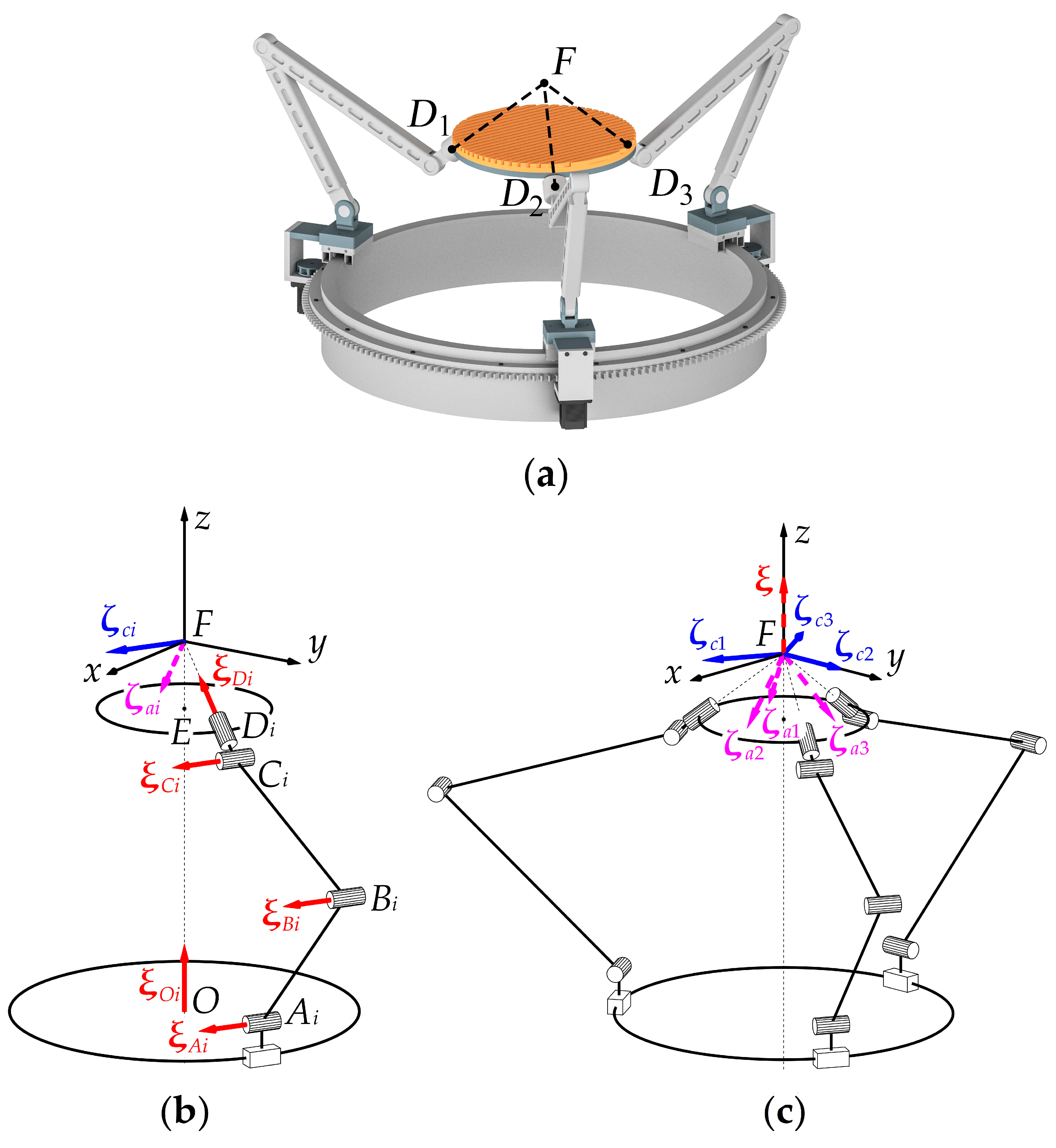
3. Modified Mechanism
We can avoid the design problems mentioned above if we place plane
AiBiCi vertically (
Figure 2a). In this case, the adjacent joint axes in each chain are either parallel or orthogonal to each other (
Figure 2b); it is much easier to provide such a design in a physical system. In this arrangement, however, vectors
of all the chains will be parallel to the horizontal plane—the space of constraint wrenches
, given in Equation (2), will be two-dimensional (
Figure 2c). Therefore, the moving plate will gain an additional DOF: a translational motion along axis
Fz. Since only three actuators drive the carriages, the space of constraint wrenches
and actuation wrenches
will be five-dimensional. We have an uncontrolled translational motion of the moving plate along axis
Fz, defined by twist
reciprocal to all
and
:
The problem of the uncontrolled translational motion of the moving plate can be addressed using two approaches:
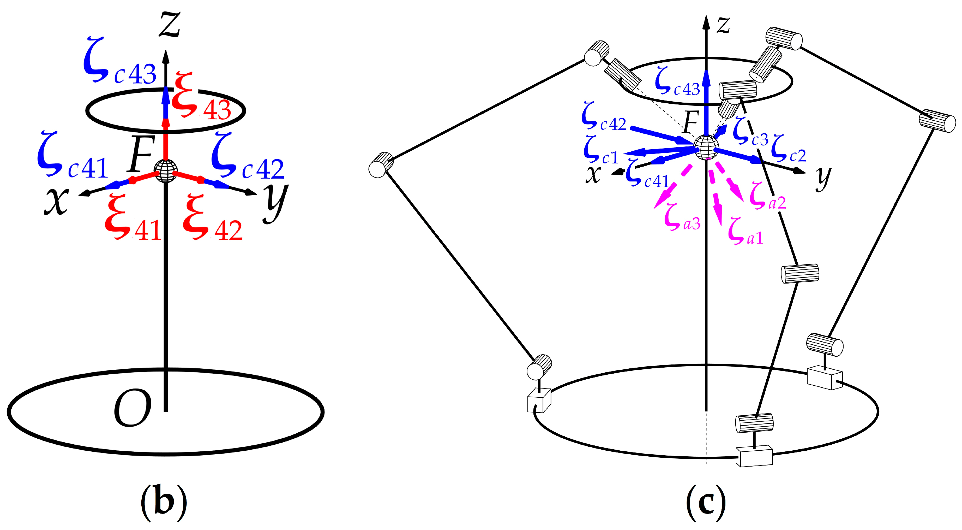
The first straightforward approach requires one of the joints Ai, Bi, or Ci to be actuated in at least one leg. In this case, we can determine an additional actuation wrench, depending on the selected joint; for a general mechanism configuration, this wrench will be independent of other constraint and actuation wrenches. Therefore, the plate wrench system will be six-dimensional, the plate vertical motion will become controlled, and the mechanism will have four (controlled) DOFs. This approach preserves the advantages of the original topology but may lead to load distribution problems, requiring a specific design for a chain with the auxiliary actuator. On the other hand, we can introduce additional actuators in each leg, making the mechanism redundantly actuated. This redundancy causes new challenges, specifically regarding the mechanism control, but may be beneficial for certain mechanisms and help to enlarge the workspace or avoid singularities. For the discussed mechanism, however, these benefits are questionable.
The second approach requires including an additional leg with a different topology. This leg should impose constraint or actuation wrenches on the output link preventing its vertical motion. Such a solution also redistributes an external load to the new leg, allowing the main three chains to be more lightweight.
There are several ways to realize this approach. The simplest one is to add a passive spherical joint to the required location of point
F and connect it directly to the moving plate (
Figure 3a). Such “leg” has trivial twist and reciprocal (constraint) wrench systems given below (
Figure 3b):
where twists
,
, and
correspond to motions in the spherical joint, and constraint wrenches
,
, and
correspond to the constraints that prevent any translational motion of the moving plate. In these screw notations, the first number in the subscript is always “4” and refers to the fourth chain.
Constraint wrenches (6) and (2) span a three-dimensional constraint space that leaves the moving plate only with rotational DOFs. With actuation wrenches (3), we obtain a six-dimensional wrench system (
Figure 3c); therefore, the plate motion is controllable (in non-singular configurations).
Such trivial leg design requires point F to be placed “inside” the mechanism between its base and the moving plate. This design, however, may cause problems in some applications in which we prefer a rotation center to locate within the workspace.
A natural development of the design above would be to use an actuated prismatic joint along with the spherical one (
Figure 4a). Suppose we add a
PS chain (the underline means the joint is actuated) with a spherical joint placed at point
F and a prismatic pair directed along the vertical axis. We can define the twist and wrench systems of this chain as follows (
Figure 4b):
where twists
,
, and
correspond to motions in the spherical joint; twist
corresponds to a motion in the prismatic joint; constraint wrenches
and
correspond to constraints that prevent translational motions of the moving plate parallel to the horizontal plane; actuation wrench
corresponds to a force transmitted to the moving plate.
Constraint wrenches (8) and (2) span a two-dimensional constraint space that leaves the moving plate only with three rotational and one translational DOFs. In contrast to the design in
Figure 2a, these constraint wrenches together with actuation wrenches (3) and (9) constitute a six-dimensional wrench system (
Figure 4c), so the mechanism is controllable and has four DOFs. Moreover, according to expression (9), the vertical motion is decoupled from the spherical one: we can use the fourth chain to set the location of point
F and the other three chains to perform spherical motions. In practice, we can also replace the
PS chain with
PRRR, R
PU, or other chains [
34], which provide the moving plate with a similar wrench system.
The first disadvantage of such leg design is similar to the previous case: we should place the spherical joint in point F, and such structure can limit practical applications. Moreover, we should also ensure the axis of the prismatic pair is vertical. Otherwise, the mechanism will be affected by additional unwanted stresses caused by its over-constrained structure. This is the second disadvantage of the proposed leg design.
We can address the problems above by replacing a
PS leg with a kinematic chain that does not impose any constraints (
Figure 5a): S
PS, S
PU, or similar [
34]. For example, suppose we use an S
PS chain attached to the base at point
M and to the moving plate at point
N. We can write the following twist system and actuation wrench for this chain (
Figure 5b):
where twists
,
, and
correspond to motions in the plate spherical joint; twist
corresponds to a motion in the prismatic joint; twists
,
, and
correspond to motions in the base spherical joint; actuation wrench
corresponds to a force transmitted to the moving plate;
is a unit vector directed along the axis of the prismatic pair;
and
are vectors from point
F to points
M and
N, respectively.
The S
PS chain does not impose any constraints, and the plate motion is constrained only by two-dimensional constraint space (2); the moving plate has three rotational and one translational DOFs. If we augment these constraint wrenches with actuation wrenches (3) and (11), we will obtain a six-dimensional wrench system (
Figure 5c); the mechanism is controllable and has four DOFs. We can achieve similar results for other chains such as S
PU or U
PS.
Using the fourth chain that does not constrain the plate motion allows us to avoid the drawbacks of the
PS chain: we can attach the fourth chain to an arbitrary point of the moving plate and place point
F “outside” the mechanism (
Figure 5a). In this case, however, we lose the decoupling and reconfiguration possibility. To see this in detail, suppose we use the S
PS chain, where point
N does not coincide with
F, and fix its drive. The moving plate becomes constrained by two-dimensional constraint space (2) and wrench (11), which we can treat as a constraint wrench. Point
F becomes fixed in space because a vector part of wrench (11) has a nonzero projection on the vertical axis. This wrench does not depend on (2), so we can find three linearly independent twists,
,
, and
, reciprocal to (2) and (11) that define plate DOFs. By simple inspection, we find two of these twists: they are zero-pitch twists, which axes pass through point
F and axis of
(
Figure 5c):
where
is a unit vector directed along
.
We cannot, however, find zero-pitch twist , reciprocal to (2) and (11), independent of and , and with an axis passing through point F. This means we cannot treat plate possible motions as spherical ones about point F, and we cannot perform the spherical motion using the remaining three chains with the carriages.
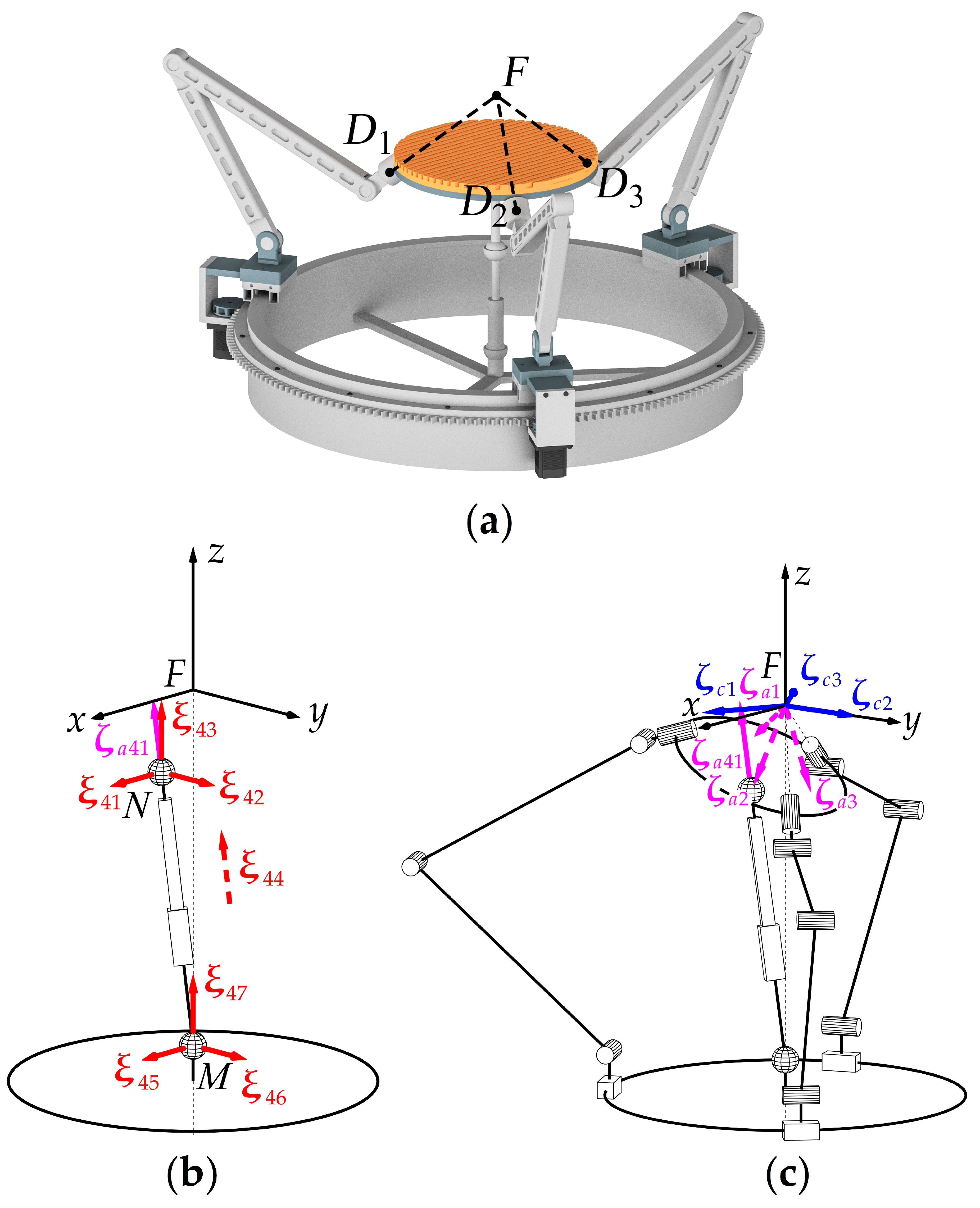
If, on the other hand, points
N and
F coincide (
Figure 6), we obtain the decoupled vertical motion and can use the fourth chain to set the location of rotation center
F. Moreover, if points
N and
M both lie on the vertical axis, the length between these points is exactly the height of point
F above the base plane. In designing a physical system, we should decide what is more important for practical applications: to have a decoupled motion and a reconfiguration possibility or to have the center of a spherical motion “outside” the mechanism.
Thus, we can see that an auxiliary central leg can improve the original design. However, since all vertical forces will be redirected to this leg, one can argue that this may lead to issues such as instability, dynamic underperformance, and imbalance. When point F coincides with point N, the central leg will only rotate about its longitudinal axis or change its length, and mechanism dynamics should not be affected. If the central leg connects to the output link at an arbitrary point, the situation should not become drastically different because the leg motion will still be of less magnitude compared with the three other legs. Furthermore, since the central leg allows reducing the mass of other legs, the overall net dynamic effect may actually be positive. As for instability or imbalance, the central leg will only work under tensile stresses, which are far less dangerous than bending ones and can be easily managed. All forces, except for vertical ones, will still be distributed along the main three legs, contributing to mechanism stability.
4. Conclusions
The article has introduced several novel parallel mechanisms with a spherical motion of the output link. Each mechanism has a circular guide with driving carriages; such a design allows the output link to perform a continuous rotation about one of the axes. This feature extends the practical applications of the mechanisms, including the medical ones.
At the beginning of the work, we considered the original spherical mechanism, which was used later as a basis for other designs. We performed its mobility analysis and verified the motion pattern of the output link. To solve this problem, we first analyzed motion twists, constraint wrenches, and actuation wrenches for one kinematic chain and, next, considered the wrench system for the entire mechanism.
The original spherical mechanism had several drawbacks, and we modified its design to eliminate them. The modified design, however, led to an uncontrolled translational motion of the output link. We considered two approaches to address this issue: using actuation redundancy and introducing an additional kinematic chain. The latter approach can be realized by three different techniques: (1) with a passive chain that has no actuators, (2) with an actuated chain, which makes the mechanism over-constrained, and (3) with an actuated chain, which does not impose any additional constraints. We examined all the cases and verified the proposed techniques using the screw theory. Each method has its own pros and cons; moreover, a rational design of the additional kinematic chain allows us to make the mechanism reconfigurable and vary the position of the spherical motion center. Such reconfigurability also extends the functional capabilities of the proposed systems.
The subsequent research of this study will have two major directions. The first one will be more theoretical and consist of kinematic and dynamic analyses, including inverse and forward kinematics, workspace evaluation, determination of singularities, and composing equations of motion. The second direction will use these theoretical foundations for the optimal mechanism design concerning particular applications.


