Article

Validating Safety in Human–Robot Collaboration: Standards and New Perspectives

1
Institute of Intelligent Industrial Technologies and Systems for Advanced Manufacturing, National Research Council of Italy, 20133 Milan, Italy
2
Fraunhofer IFF, 39106 Magdeburg, Germany
3
Université Paris-Saclay, CEA List, F-91120 Palaiseau, France
4
CEA, CEA Tech Grand Est, F-57075 Metz, France
5
Roessingh Research and Development, 7522 AH Enschede, The Netherlands
6
Department of Biomedical Signals and Systems, University of Twente, 7522 NB Enschede, The Netherlands
7
Department of Biomechanical Engineering, University of Twente, 7522 NB Enschede, The Netherlands
8
Department of Robot Technology, Danish Technological Institute, 5230 Odense, Denmark
*
Author to whom correspondence should be addressed.
Robotics 2021, 10(2), 65; https://doi.org/10.3390/robotics10020065
Submission received: 15 February 2021 / Revised: 22 April 2021 / Accepted: 28 April 2021 / Published: 29 April 2021
(This article belongs to the Special Issue Human–Robot Collaboration)

Abstract

:
Human–robot collaboration is currently one of the frontiers of industrial robot implementation. In parallel, the use of robots and robotic devices is increasing in several fields, substituting humans in “4D”—dull, dirty, dangerous, and delicate—tasks, and such a trend is boosted by the recent need for social distancing. New challenges in safety assessment and verification arise, due to both the closer and closer human–robot interaction, common for the different application domains, and the broadening of user audience, which is now very diverse. The present paper discusses a cross-domain approach towards the definition of step-by-step validation procedures for collaborative robotic applications. To outline the context, the standardization framework is analyzed, especially from the perspective of safety testing and assessment. Afterwards, some testing procedures based on safety skills, developed within the framework of the European project COVR, are discussed and exemplary presented.

1. Introduction

The concept of human–robot collaboration (HRC), based on the synergic work of robots and humans, questions the traditional paradigm of physical barriers separating machines and workers, lowering fences and closing distances. This paradigm shift was enabled by two main technological factors: the integration of safety-related features in the robot architectures and control systems and the use of multi-modal interfaces for more intuitive, aware and safer human–robot interaction (HRI) [1,2]. Moreover, thanks to the advances in artificial intelligence, robots can adapt their tasks and behaviors, becoming suitable to act in unstructured scenarios and interacting with unskilled and undertrained users.
The statistics show that, in the last years, several robot fields are increasing their markets, such as: robots for domestic tasks, entertainment robots, logistic robots, robots for public environments, defense applications, inspection and maintenance robots, professional cleaning, field robots, powered human exoskeletons, medical robots, construction and demolition [3]. Focusing just on the medical and healthcare domain, a non-comprehensive list includes: surgical robotics, boosting the transition from open surgery to laparoscopic and other minimally invasive surgical procedures [4]; bionic prostheses, enabling wearers to autonomously carry out their daily activities; the category of “RACA” robots, including a variety of devices, either wearable or static, to perform rehabilitation, assessment, compensation and alleviation (RACA); and caregiver robots, which are expected to play a fundamental role in aging societies [5]. In the agri-food sector, autonomous mobile robots provided by navigation and perception technologies represent a breakthrough, with the potential of performing mass phenotyping, crop management, and selective harvesting [6].
The importance of robots was underlined by the recent pandemic, as it is recognized that robot adoption can be extremely useful to support social distancing. Accordingly, robotic-assisted surgery has become a safe alternative, protecting the patient, the operating team, and saving resources for people with COVID-19 [7]. Due to their safe nature and possibility of “learning from demonstration”, collaborative robots can be implemented as sterilizable physical mediators between patients and clinicians, for example, for mass swabbing and physiotherapy treatments; at the same time, autonomous robots can perform UV sterilization of the environments and optimize internal logistics of health facilities [8]. Furthermore, from the perspective of social distancing, robotics can enable pandemic-sustainable travel, tourism and hospitality, performing environment sterilization, measuring body temperatures, welcoming and entertaining [9].
The aforementioned examples are characterized by different levels of HRI, spanning from teleoperation to workspace sharing and synergistic co-control. Taking a step back, one can observe that boundaries between industrial and service robotics are becoming blurred [10] and HRC is assuming a broader role, becoming applicable to a wide variety of robot applications in which the close interaction between human and robots is envisaged. However, the implementation of robots sharing space with humans, either to increase productivity rates, relieve us from heavy and repetitive tasks or mitigate certain hazard sources, always has to consider the mechanical hazards associated with HRC. Furthermore, the implementation and observance of safety is closely related to overall task performance, as safer interaction enables lower barriers and can help robots to reach their full potential.
In such a rapidly evolving landscape, in which industrial and service robotics become increasingly closer, identifying, interpreting and fulfilling the applicable standards for robot safety is critical. Based on the experience of the authors with robot end-users, manufacturers and integrators, the promotion of cobot technologies in different domains is slowed down by the path towards ensuring safety. This is due to both the limited knowledge about relevant standards and the absence of clear procedures to prove the compliance in these standards [11,12]. To address this need, a novel cross-domain validation approach is proposed in this paper, based on testing procedures made available through an online toolkit.

1.1. Safety in HRC

Increasing safety in collaborative robot operations is a goal pursued at different levels. Collaborative robots are intrinsically safer, but the implementation of external sensing strategies further improves safety, and safety-related systems can be used to enable HRC with traditional robots [13]. The research community is addressing several issues related to sensing, robot hardware and safeguarding measures; the main drivers concern increasing the perception of both robots and humans, lowering the potential damage due to mechanical features, control strategies or external protections, providing user-friendly programming strategies [1]. Aiming at increasing collaboration synergy and safety, human–robot interfacing can be enhanced by implementing different technologies, such as robot integrated vision, voice recognition, head-mounted displays for augmented reality, haptic-based devices and even the detection of bio-signals [2].
Safety-related aspects have a relevant impact in the design of HRC application, as hazard identification, risk assessment and the identification of risk mitigation strategies become even more crucial. In [14], a typical process is described, demonstrating that an appropriate modeling of safety aspects can reduce both the design time and the final workspace required by the layout. In a recent review [15], it is shown how the research outputs concerning safety and ergonomics are increasing, in the last years, with the rise of collaborative robotics, identifying four main clusters of interest: contact avoidance, contact detection and mitigation, physical ergonomics, cognitive and organizational ergonomics. Even if the two former categories are more widely addressed, the authors claim that ergonomic issues will play a major role when the advances in contact avoidance strategies will push the limits of HRI, leading to a complementarity of these aspects towards safe and efficient HRC.
Concerning the evaluation of safety in HRC, some approaches use objective measures to plan and evaluate the performance of applications featuring “speed and separation monitoring” collaborative scenarios [16,17]. Unfortunately, they also demonstrate the difficulties in identifying the point in time during a robot’s trajectory where a specific algorithm is the least safe, requiring either a simulation or a test with the completed system.
Even if these approaches can provide a certain measure of the HRC safety, they are not aimed at the validation of robotic applications with reference to directives and standards. Furthermore, they are targeting robot experts dealing with HRC scenarios in the industrial domain, while the ambition of the present work is to meet the needs of a diverse user audience, operating in different domains with the potential for implementing cobots in a wide range of tasks.

1.2. Paper Contribution

The risks related to an autonomous robot acting in a public environment are similar to the ones typical of a driverless mobile robot in industry. In the same way, similar risks characterize a manipulator for collaborative assembly and one implemented for delicate health diagnostic procedures. This leads the consideration that the specific safety-related testing procedures could rely on a common base of knowledge and experience. It is also worth observing that, even in the fields characterized by higher levels of expertise, close HRC brings new challenges for safety verification and validation. Accordingly, the analogue hazards make the guidance for clear, step-by-step testing procedures a common need of both experienced and new users.
The aim of this paper is to outline emerging necessities and possible trends concerning safety testing procedures for cobot applications, based on an overview of the landscape of relevant standards for the validation of safety, and to describe a new cross-domain approach based on safety skills and testing protocols. In this context, we refer to “safety skills” as the capability of a robotic system to reduce a specific risk and to “protocols” as step-by-step instructions for executing validation measurements. It is a belief of the authors, indeed, that clearer safety assessment processes allow cobots to be used with more confidence in more situations; this can be a valuable boost to increase the variety of cobots on the market and the variety of services cobots can offer to the general population. As a remark, the proposed protocols are not intended to substitute standards; they represent instead a tool to guide and facilitate the users in the identification of relevant standards and their fulfillment.
The paper is organized as follows. In Section 2, the standard framework is addressed; building on the overview of all the relevant standards, some recent publications dealing with detailed test procedures, are described and gaps with user needs are highlighted. Section 3 deals with the proposed cross-domain approach, which is based on the definition of safety skills and the development of testing protocols, while in Section 4 some exemplary cases of protocol application are reported.

2. Robot Safety: The Regulatory Framework

2.1. Overview

The main regulation in the European community dealing with robot safety is the Machinery Directive 2006/42/EC [18]. It is translated in all the national languages and transposed into laws by each member country. A robot falls in the scope of the Machinery Directive, as it is composed of “linked parts or components, at least one of which moves” and being actuated by a drive system. A programmable robot supplied by a robot manufacturer is regarded by the Machinery Directive to be a “partly completed machinery”. This means that the robot itself is not CE-marked for Machinery Directive, but that all information needed by integrators to ensure safety is provided by the robot manufacturer. To be considered as a “completed” machinery, it must be designed or integrated for a specific application. In industrial robotics, the concept of machinery applies to robotics applications or robotic cells and whereby the integrator is considered to be the manufacturer. In other fields, such as robots for consumers, assistive robotics or medical robotics, the intended use must be clearly defined.
The Medical Device Regulation EU 2017/745 [19] applies to rehabilitation and, more generally, to healthcare-related activities. It replaced the Medical Device Directive, which focused mainly on the design of the system, providing more safety considerations over the entire device lifetime [20]. The Medical Device certification is strongly based on an “intended use” and valid only for this “intended use” for which clinical evidence must be provided. So, in accordance with the Machinery Directive, a generic robot without his specific application cannot be certified. It is worth noting that, for a robotic medical device, the Machinery Directive must also be observed. Other directives may apply depending on the field of use, such as the General Product Safety Directive [21], when a robotic device is made available on the consumer market, or a type-approval regulation when a robot becomes a vehicle (this category is outside the scope of this paper). Finally, there are more general relevant directives, such as the Low Voltage Directive [22], the Electromagnetic Compatibility Directive [23], and the Radio Equipment Directive [24].
Standards are technical reference documents, representing the consensus on the state of the art and compliance to them is not mandatory. Technical committees (TCs) are in charge of developing standards and the main committee within ISO for industrial and service robotics (excluding toys and military applications) is the ISO TC 299 “Robotics”. Robotics ISO standards from this group mainly address vocabulary, performance and safety. Concerning safety, they describe solutions gathering a certain level of consensus within the specific community. Indeed, robot manufacturers typically take part in standardization committees, along with integrators, end-users and stakeholders representing public health and health insurance. “Harmonized” standards are recognized by a European standard organization as fully compliant with the relevant directive or regulation; thus, their application provides the so-called “presumption of conformity”. The most relevant standards for robot safety from the perspective of HRC are listed in Table 1.
Safety standards are categorized into: type A, providing the basic design principles and valid for all machines; type B, which are generic standards concerning either specific aspects of safety or devices for safeguarding; and type C, covering particular classes of machines (i.e., robots) and having precedence over type A and B. Accordingly, for robots belonging to the categories of industrial robots or personal care robots, type C standards are the main reference. The list reported in Table 1 is not comprehensive of all the robotics-relevant type B standards, as it is limited to standards dealing with HRC, either explicitly or not. An up-to-date list of all the robotic standards, which can be filtered by application domain and device type, can be found in COVR Toolkit [25].
The Machinery Directive sets out the “Essential health and safety requirements relating to the design and construction of machinery”. Fulfilling these requirements is based on an “iterative process of risk assessment and risk reduction” for which one can rely on the standard ISO 12100 [26] (type A). It should be noted that the medical device safety is addressed by a dedicated standard for risk management, the ISO 14971 [27]. The Machinery Directive promotes the integration of safety in all design stages, giving priority to inherent safety, followed by protective measures, and, lastly, by organizational measures, such as user training and personal protective equipment.
The ISO 10218 is a type C standard for industrial robotics, divided into two parts: the first [28] dealing with robots considered as “partly completed machinery” and the second [29] addressing integrated applications, which are the machineries to be considered in compliance with the Machinery Directive. Even though harmful HRI had already been addressed in the first versions, intended physical interaction has been introduced in 2009 in both 10218-1 and -2, by describing “hand-guiding” (HG) and “power and force limiting” (PFL) operating modes. The possibility to avoid safeguards by the use of distance sensing was introduced with “safety-rated monitored stop” (SRMS) and “speed and separation monitoring” (SSM). The safety requirements for these collaborative modalities are currently under development for the upcoming revision of ISO 10218 (to be published in 2022), as will be addressed in the following paragraph.
Technical specifications (TS) and technical reports (TR) are different ISO deliverables. TS address work still under development but with a chance to be included in an international standard, while TR contain other kinds of information, for example, the perceived state of the art of a specific topic. ISO/TS 15066 [30] represented a milestone among HRC standardization. Besides including information regarding collaborative robot system design, hazard identification, risk assessment and the requirements for the applications, it provides a more detailed description of the collaborative modes SRSM, SRSS, PFL, HG and limit values for quasi-static and transient contact forces are illustrated.
Table 1. List of the most relevant standards dealing with safety requirements in HRC.
IDStandardHRC RelevanceTypeHarmonized
ISO 12100:2010 [26] Safety of machinery—general principles for design—risk assessment and risk reductionRisk assessmentAYes
ISO 13855:2010 [31] Safety of machinery—positioning of safeguards with respect to the approach speeds of parts of the human bodySuitable for SSMBYes
ISO 18497:2018 [32]Agricultural machinery and tractors—safety of highly automated machinerySafety requirements, verificationBYes
ISO 13851:2019 [33]Safety of machinery—two-hand control devices—principles for design and selectionSuitable for HGBYes
ISO 10218-1:2011 [28]Robots and robotic devices—safety requirements for industrial robots—part 1: robotsHRC operation
requirements
CYes
ISO 10218-2:2011 [29]Robots and robotic devices—safety requirements for industrial robots—part 2: robot systems and integrationHRC operation
requirements
CYes
ISO 13482:2014 [34]Robots and robotic devices—safety requirements for personal care robotsGuidance for safety (lifecycle)CYes
ISO 3691-4: 2020 [35]Industrial trucks—safety requirements and verification—part 4: driverless industrial trucks and their systems Human detectionCYes
IEC 80601-2-78: 2020 1 [36]Medical electrical equipment—part 2-78: particular requirements for basic safety and essential performance of medical robots for rehabilitation, assessment, compensation or alleviationSafe HRI with RACA robotsn.a.No
ISO/TS 15066:2016 [30]Robots and robotic devices—collaborative robotsFocused on HRCTSn.a.
ISO/TR 23482-1:2020 [37]Application of ISO 13482—part 1: safety-related test methodsTesting procedures for ISO 13482TRn.a.
ISO/TR 20218-1:2018 [38]Robotics—safety design for industrial robot systems—part 1: end-effectorsRequirements for end-effectors TRn.a
ISO/TR 20218-2:2017 [39]Robotics—safety requirements for industrial robots—part 2: manual load/unload stationsReq. for load/unload stationsTRn.a
1 IEC 80601-2-78 belongs to a series of particular standards that can modify, replace or delete requirements of the general standard IEC 60601-1:2020 (Medical electrical equipment—part 1: general requirements for basic safety and essential performance).

2.2. A New Trend in Standardization?

If in domains characterized by well-established validation practices and reference standards, such as the industrial field, the presence of collaborative robots brings new challenges in the assessment of human–robot interaction, the increasing spread of robots in environments shared with humans generates new application scenarios, involving new types of users. An inexpert end-user can harbor the false perception that the mere implementation of a collaborative robot is sufficient to ensure safety, due to its low weight, ease of use and even friendly appearance. As a result, these two parallel trends—the spread of robots among humans and the increase of end-users new to the robot world—increasingly pose the need of clear procedures for testing robots sharing their workspaces with humans. There are recent signals that the standardization world is moving to meet this need and provide the required procedures. In Table 2, the tests currently available in these standards are listed.
The new version of the ISO 10218-2, currently under development, is expected to give greater attention to collaborative applications. As a “draft international standard” (DIS), the ISO/DIS 10218-2 [40] was published in late 2020 and is currently under evaluation. Collaborative applications are identified as characterized by one or more of three technologies: “hand-guided controls” (HGC), “speed and separation monitoring” (SSM), and “power and force limiting” (PFL). Specific risk assessment is envisaged for potential human–robot contact conditions, as well as related passive safety design measures and active risk reduction measures. To the latter category belongs the safety function “monitored-standstill”, corresponding to the capability of performing the SRMS collaborative mode, no longer addressed. Furthermore, new annexes are specifically dedicated to HRC. Among these, Annex L describes how to calculate the protective separation distance in SSM and Annex M reports the limits for quasi-static and transient contact. These annexes incorporate the information previously provided by the ISO/TS 15066 [30]. The most relevant from the perspective of safety verification and validation testing is Annex N, dedicated to pressure and force measurements in PFL robotic applications.
The recently published ISO 3691-4 [35] provides some testing procedures. It applies to driverless industrial trucks, which are powered trucks, designed to work automatically. Examples of trucks falling in this category are all-automated guided vehicles, autonomous mobile robots, bots, automated guided carts, tunnel tuggers, under carts, etc., whereas trucks guided by rails or other mechanical means or controlled remotely are excluded. Therefore, industrial mobile platforms and several types of mobile service robots are included. From the perspective of the safety assessment, the relevant section is the one related to the “verification of safety requirements and/or protective measures”, in which testing procedures are specified, including tests for the detection of persons and stability tests.
As a technical report, the ISO/TR 23482-1 [37] “describes test methods which are guidelines to verify compliance to the requirements of 13482”, which, in turn, describes “safety requirements for personal care robots”. In the TR, test conditions are provided as general rules and practices for the performance of all the tests. Afterwards, a list of several tests is provided, organized depending on the related hazard, along with a detailed description of the test principle, apparatus, procedure, and pass/fail criteria.
Even if the ISO 18646 standard series deals principally with robot performance criteria and assessment, this aspect is closely related to safety, especially in the case of performance related to safety-related functionalities. Accordingly, some performance testing procedures are reported in Table 2, extracted from the ISO 18646-1 [41] and the ISO 18646-2 [42].

2.3. Analysis of the Gaps

Whereas, 20 years ago, industrial robots were almost solely used for high volume manufacturing, today the same robot manipulator can be used for manufacturing, logistics, rehabilitation, or even agricultural applications. This can lead to uncertainty with respect to safety and applicable standards, especially due to the domain-specific organization of international safety standards, through two specific ways. On the one hand, in situations where innovations occur faster than standardization, there are not always relevant domain-specific standards for the application in question. On the other hand, combinations of device types can lead to conflicting issues from different safety standards. An example is a mobile platform equipped with a robot manipulator. The forces specified during contact are different when considering an industrial manipulator (in the ISO/TS 15066 [30]) or an autonomous truck (ISO 3691-4 [35]). Further challenges arise when considering what separation distances to apply, as the ISO/TS15066 [30] also specifies that the approach speed of humans needs to be taken into account, whereas the ISO 3691-4 [35] does not.
While adherence to standards is not legally binding, they do represent the state of the art and can be extremely helpful for considering the safety of collaborative robotics applications. A streamlined approach that offers robotics stakeholders the means to conceptually talk about the safety of their system, regardless of the specific domain, would be helpful here. Furthermore, it would be extremely helpful to the robotics community if the same approach were to extend to methods for validating the implemented risk reduction measures. This approach should, however, respect the fact that there are a wide variety of technical means available for implementing the safety.

3. Safety Skills and Testing Protocols in a Cross-Domain Perspective

In the consolidated practice, boundaries between different robotic domains are well-defined and recognized. One typical example is that HRI with robotic medical devices can also generate physical benefits, balancing the risks associated to their operation, while this is not applicable for other types of robots. However, this approach can represent a limit when similar hazards have to be addressed in different domains; in these cases, indeed, cross-domain fertilization can provide an extra gear to define the best practices for the verification of safety requirements. This section proposes a safety verification approach based on the definition of cross-domain safety skills and the development of testing protocols, drafted on the basis of practical needs and updated by expert consultations and by the examination and addressment of real application cases. In Section 3.1, the safety skill concept and the skill-based approach is described, whereas the testing protocol structure and the list of the protocols are addressed in Section 3.2.

3.1. The Skill-Based Approach

When considering the safety of collaborative robotic systems, it is essential to start with a risk assessment, whereby hazards specific to a concrete application are identified and risk reduction measures (RRM) are chosen. The operation methods for collaborative robotics applications, such as the SRMS, SSM, PFL, HG, as currently defined by the ISO 10218, can be implemented through a variety of technical means and offer the planner a level of abstraction to discuss and consider the safety of the application. These definitions may become challenging when other device types and domains rather than manufacturing are considered, such as industrial robotics for rehabilitation or mobile robots for agriculture.
To overcome this challenge, the concept of safety skills has been proposed in [43]. Safety skills are defined as an abstract representation of the ability of the robot system to reduce some risk, i.e., to deploy suitable RRM. The implementation of the protective measure can be executed in a number of ways. A safety skill therefore indicates what kind of protection is desired and is independent of the execution of how this protection is delivered. A further characteristic of safety skills is that they can be validated for specific applications at a system level.
A two-pronged approach towards the definition of cross-domain safety skills was applied. In addition to an identification of existing operating modes from available standards, an analysis of possible hazards and risk reduction methods for a large variety of applications featuring a combination of different robotic device types for six domains (manufacturing, rehabilitation, agriculture, civil, logistics, and consumer/home) was executed. While the latter analysis was quite large, it cannot be considered comprehensive, as robotics are increasingly being used for new applications in an even wider variety of domains than those analyzed. Nevertheless, the concept of cross-domain safety skills is explicitly conceived to deal with the novelty of future robotics applications and provide guidance for how to consider their safety. The safety skills that were identified and associated and known operating modes from existing standards are listed in Table 3.

3.2. Protocols for Skill-Based Validation of Applications

As per their definition and scope, skills are abstract concepts applying to different collaborative operation scenarios. Their proper and effective application depends on several operation features, such as the domain in which they are tested, the design of the robotized operation, and the type of robotic system involved. Verifying and validating the application of a safety skill in a specific scenario corresponds to assessing the application’s safety features from the perspective of the specific skill, providing evidence of the effectiveness of the safety measures implemented with reference to the relevant standards. Such an assessment is not a trivial task, as it requires, in order: (i) a comprehensive knowledge of the applicable regulation landscape, (ii) critical awareness of the relevant physical metrics and performance data to be measured, (iii) technical knowledge of the most appropriate testing equipment and methodologies, (iv) the production of clear, complete and self-explanatory reports.
A suitable methodology to validate safety skills relies on the application of testing protocols, developed with the specific scope of providing a step-by-step guide on how to execute a validation measurement to check the safety of a robotics application. To exploit the potential of the cross-domain approach, protocols have to be general procedures, applicable in several domains and individuated only by two fundamental variables, that are the safety skill to be validated and the robotic device involved in the specific task to be used for the validation. To maximize their impact, protocols have to pursue the following scopes:
-
increasing the familiarity in the robotics community with possible measuring techniques;
-
informing protocol users of what aspects of their risk analysis and system behavior are relevant for the validation.
In fact, the risk assessment, conducted as per the relevant standards, is a fundamental, preliminary step for the validation of a safety skill. It is necessary, indeed, to define the conditions in which protocol procedures must be applied; these conditions depend on the specific installation, environment, task, user awareness, safeguarding measures provided by the manufacturer, prescribed protective measures, and so on.
A set of safety skill validation protocols is available in COVR Toolkit [25]; they are designed for the system-level evaluation of the safety performance. To cope with the aforementioned requirements, the structure of a protocol is organized to guide the user in all the steps of the safety skill validation (see Table 4). Aiming at enhancing clarity of contents and usability, relevant stakeholders and protocol users can provide feedback during the whole protocol lifecycle. As a result, the available protocols are proven testing procedures, intended to be dynamically and periodically updated according to the increasing usage feedbacks. They are indeed published once a “Protocol Readiness Level” 7 (PRL, defining the level of protocol advancement on a nine-level scale) is achieved and they are open for further user feedbacks, collected by means of specific questionnaires.
The development of a protocol depends on the analysis of the meaningful combinations of safety skills and robot device type, as reported in Table 5. The list of robotic device types reported in the table is based on the systems typical of the industrial practice, whose implementation and use are extended to several application domains (i.e., robotic arms in assistive robotics or mobile robots in the agricultural domain) and on the robotic systems typically used in the rehabilitation field. This set represents a first nucleus of devices, but further systems can be included to develop more validation protocols. In some cases, for the same device–skill combination, several protocols were developed, considering the use of different measuring equipment. Likewise, there can be specific operation conditions, which can variate depending on task design or the context of use, leading to different testing approaches. These aspects result in the development of several protocols for the same device–skill combination, individuated by the increasing numbers in Table 5.
The list of protocols currently available in COVR Toolkit is reported in Table 6. In the table, some details are specified, in order to enable the observation of the main similarities and differences. With this perspective, the following considerations arise:
  • Protocol applicability conditions are general and valid in different scenarios. The main advantage of basing protocol development on a cross-domain perspective is the possibility of reducing their quantity, still meeting the specific needs of a wide variety of application cases.
  • The assessed metrics can be based on measured values or on Boolean variables. This is mainly related to the required testing equipment, as in the case of video cameras, the observation of the test enables analysis only on a threshold-based assessment.
  • Regardless of the test metrics, safety skills are validated based on the verification of the compliance with specific thresholds, which are provided by specific standards, or, if not available, determined by the manufacturer. None of the thresholds are proposed by protocol designers, in compliance with the protocol concept and aims.
  • To maximize the usability of protocols and, consequently, further shorten the distances between the users and the safety validation, where possible, several kinds of testing equipment and methodologies are suggested.
  • All the LIE validation protocols are based on the use of sensing devices with the same basic principle, which is acquiring normal force and pressure. Furthermore, they all can be characterized as “biofidel”, referring to the capability of reproducing the biomechanical behavior of the human body part potentially involved in the contact. This approach represents the state-of-the-art for the assessment of human–robot physical interaction, which is expected to be adopted by the relevant ISO standards. As shown in Section 2.2, this is indeed one of the new aspects introduced in the ISO/DIS 10218-2 [40] and a similar device is also envisaged by the ISO/TR 23482-1 [37].

4. Examples of Protocol Use and Application

In this Section, three application cases of the validation protocols are shown. It is worth mentioning that the process of developing validation protocols involved a clear specification of the use-case and protocol user needs, input from the experience of the protocol developers from previous measurements, and several feedback loops from users within the COVR consortium and from the projects sponsored through the cascade funding mechanism within the overall COVR project framework. The application cases hereafter reported refer to:
  • an experimental campaign, belonging to the in-house trials performed by the COVR partners, aimed at obtaining the maximum permissible velocities of a collaborative robot in some areas of the workspace;
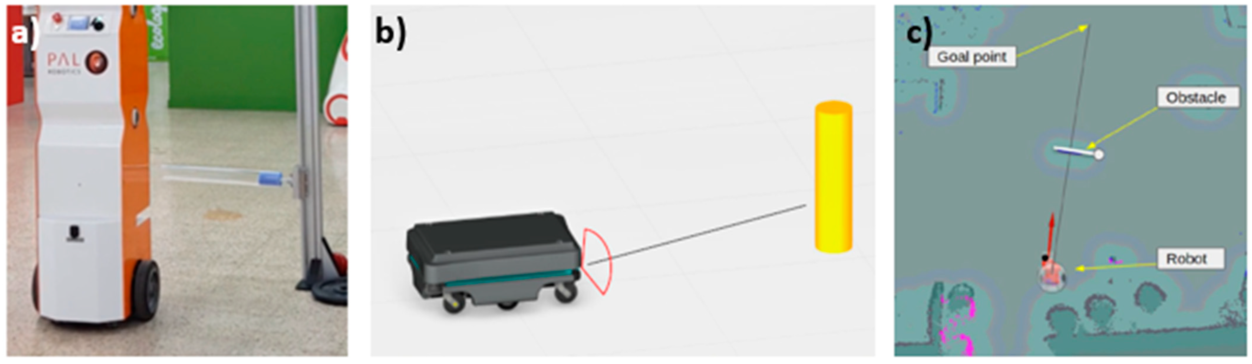
  • the validation of a mobile robot for a retail environment;
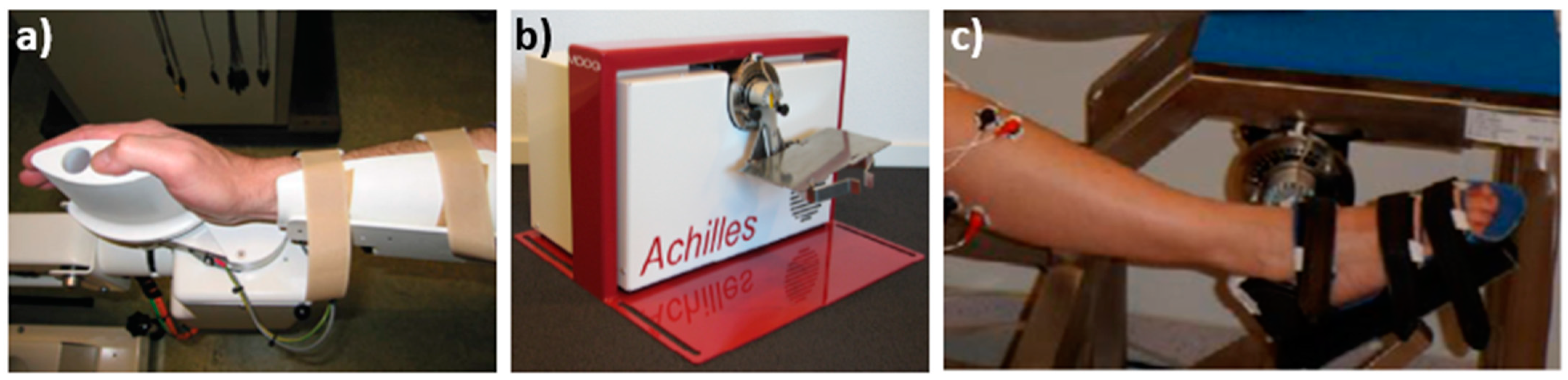
  • the validation of a rehabilitation robotic device.

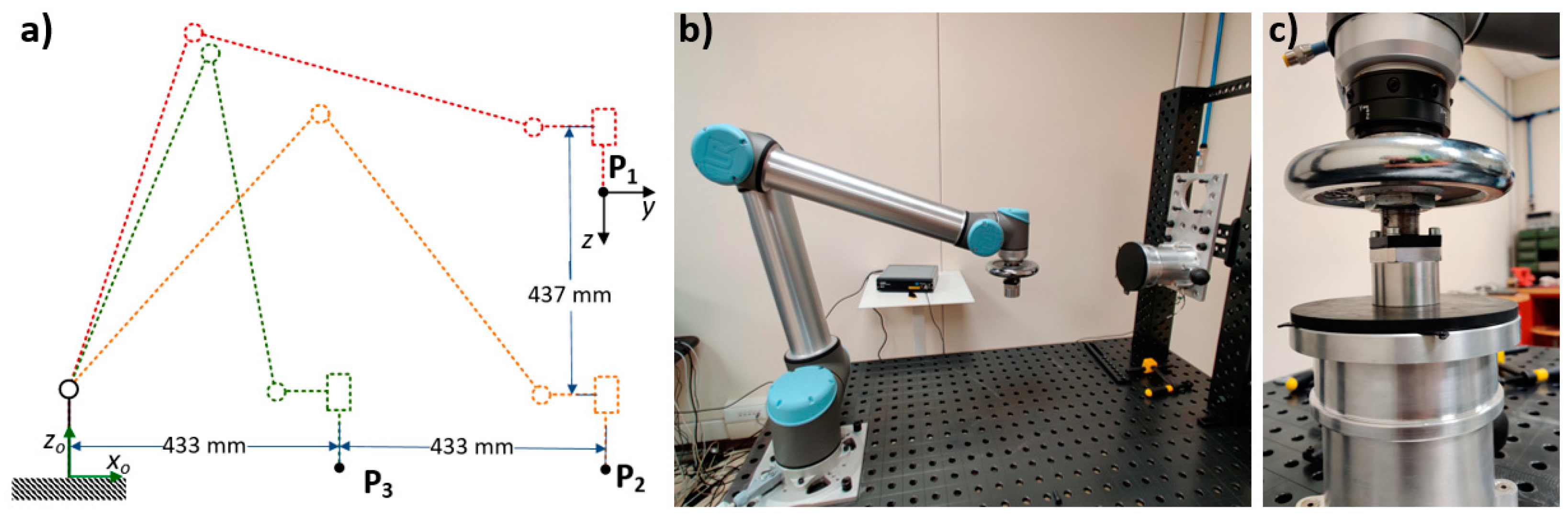
4.1. Admissible Velocities of a Robot Arm in a Shared Workspace

The test procedure described in the protocol ROB-LIE-1 “Test robot arm for collision with movable object (Impact)” was used to perform a series of impact tests in a pre-defined set of positions, in order to obtain an indication of the maximum permissible operational velocities of a Universal Robots UR10 in different areas of its working volume, with reference to specific human–robot contact scenarios. The protocol is aimed at testing the contact force and pressure affecting the operator in an unintended contact scenario with a robot with PFL functions activated, to be then compared with the force and pressure limits provided by ISO TS/15066 [30]. The contact scenario identified in the risk assessment is reproduced to obtain the force and pressure values related to the transient contact phase. The robot program from the real application is executed and the measurement takes place along the position in space where the risk analysis specifies that contact is likely to occur. The robot collides with the sensing equipment, which consists in a biofidelic load-cell sensor and a foil pressure sensor. Data is then post-processed and the peak value is obtained for the transient contact phase (tc ≤ t ≤ tc + 0.5 s, with tc representing the time in which contact occurs).
The tests carried out considered the contact of a test piece with the sternum, the abdominal region and the back of the hand at three different points (see Figure 1a) in the robot workspace. The measurements were executed at different velocities for each position (with a 50 mm/s increment for linear trajectories and 5 deg/s for the point-to-point motions). The following table reports the setup of each of the tests, performed using a GTE CBSF-75 Basic with adjustable spring and impact pad as force sensor. The obtained force values were then compared to the limits in the ISO/TS 15066 [30] to identify the permissible robot velocities for each position with the tested configurations. The results related to the tests performed in CNR-STIIMA laboratories are also reported in Table 7.

4.2. Stockbot: A Mobile Robot for a Retail Environment

The Stockbot (pal-robotics.com/robots/stockbot, accessed on 15 April 2021) mobile robot from Pal-Robotics (Figure 2a) is a mobile robot intended for the implementation in retail environments for stocking purposes during normal activity in shops. The MOB-MSD-1 “Test Mobile Platform to Maintain a Separation Distance” protocol was used to validate the ability of the robot of maintaining a safety distance from humans and obstacles. The protocol MOB-MSD-1 describes the validation procedure for a mobile robot sharing an environment with humans and objects encountered along its path, aiming at avoiding contact by keeping a safety distance in any condition. This is obtained by setting up a test using a cylindrical object as a dummy, placed vertically on the floor along the robot path. During the test, the robot, with enabled safety functions and after a warm-up phase, moves towards the obstacle and is expected to stop automatically before impacting with the obstacle. The distance between the robot and the obstacle is then acquired (Figure 2b) and compared to a safety distance, which is pre-defined depending on the application requirements and specified in the risk assessment. The test must then be repeated with different-sized obstacles.
In the Stockbot case study, a wide variety of cylindrical dummies were tested, considering the following colors and materials: matt black, bright red, mirror, cardboard, aluminum, transparent plastic, and two different dimensions. They were placed at different heights for testing by using a post with sliding guides. Tests were performed in an operating environment exactly like in real scenarios. The protocol was applied with a main modification: in order to assess the Stockbot advanced functionality of creating an alternative path when an obstacle is encountered, the robot was not expected to stop during the test, but the minimum distance from the obstacle was calculated, post-processing the acquisitions from an HTC Vive tracking system (Figure 2c), which is recognized as a suitable 3D tracking system [47]. Besides the application of the MOB-MSD-1, the robot was validated also considering other hazards (impacts, stability vs. steps or slopes) and the protocol-based test campaign enabled to successfully validate the use of the robot in shared public environments.

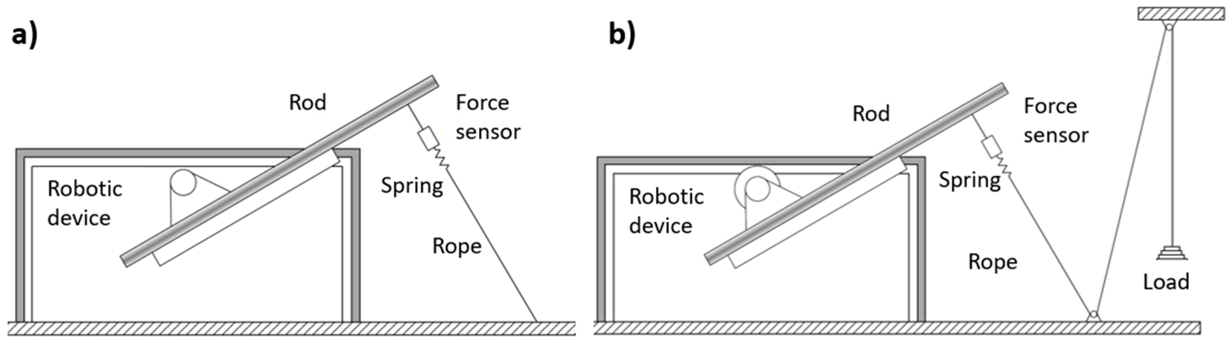
4.3. Achilles: A Robotic Device for Ankle Rehabilitation

The protocol ROB-LRE-1 was co-developed and executed in an earlier version with the partners Amsterdam UMC (location VUmc), TU Delft and LUMC (all from NL) to validate the safety of two haptic rehabilitation robots, Achilles and Wristalyzer (Figure 3) from Moog B.V. (www.moognetherlands.nl, accessed on 15 April 2021), used for diagnostics of joint hyper-resistance and quantification of passive stiffness versus reflex torque in neurological patients. They are used for the ankle and wrist joint, respectively, and can apply a torque to the human joint in two different scenarios:
  • to counteract a maximum torque applied by the human subject, maintaining a set position to determine the subject’s capabilities;
  • to generate a motion of the attached body segments within pre-defined physiologically safe torque limits.
The applied protocol includes two tests to validate (i) that the torques actually applied by the robot match those set in the robot control (“torque mode” test) and (ii) that the pre-set maximum allowed torques are not exceeded (“position mode” test). In the torque mode test, a rod is connected to the robot and then connected to the floor via a non-elastic rope with a force sensor and a spring (Figure 4). The robotic device must be set to apply an increasing torque according to a linear incremental ramp profile; torque values from the robot software are then compared to those obtained by computing the force sensor acquisitions. In the position mode test, a non-elastic rope, to which weights can be added though a pulley system, is attached to the robotic device (Figure 4). By computing the data obtained by a force sensor, the torques generated by the weights and imposed on the robot are obtained and compared to the values acquired by the robotic device. A spring dampens the force peak that may result from placement of the test weights. The safety of Achilles was validated by applying the protocol: in the torque mode test, the reliability of the torques computed by the robotic devices was proven, while in the position mode test it was observed that robot torque application was stopped before reaching the pre-set maximum torque.

5. Conclusions

This paper deals with safety-related testing procedures in human–robot collaboration. With HRC, the authors refer to all those robotic application scenarios, whether industrial or not, in which close human–robot interaction is envisaged during robot operation. The authors claim that the potential of the latest frontiers in HRC, along with the spread of robots in a variety of domains and applications, is currently limited by the difficulties faced when dealing with safety validation of the specific robotic application. This is due to the very articulated regulation and standard framework, combined with the (still) scarce availability of step-by-step testing procedures.
To address this topic, this paper first addresses the standards and European regulation within the context of safety for HRC. Likewise, an overview of all the testing procedures provided in the latest standards, useful for safety verification and validation, is provided. However, based on the experience of the authors with real applications, safety validation issues arising due to the cross-fertilization of different domains pose new challenges, whose solution often requires the consideration of non-domain-specific robotic standards and best practices as a whole. By addressing as a whole the industrial and non-industrial specific issues, analogies are highlighted, providing the foundation for an innovative cross-domain perspective.
Accordingly, a new approach is proposed, based on the definition of a selected set of safety skills that are applicable to a wide variety of robotic applications, regardless of the implementation domain. The cross-domain safety skill concept has been translated into testing “protocols”, each defined by the robotic device implemented in the task and the validated safety skill. Protocols build on standards and best practices and are aimed at providing robotic users, either non-expert or expert but dealing with new HRC challenges, with guidelines for the identifications of relevant standards and the testing procedures to fulfill their requirements. The first set of protocols was published and is freely available within the COVR Toolkit [25], and it is constantly updated based on the feedback from users and experts. As examples of protocol use, some real cases are reported in the paper, belonging to different application domains.
The proposed methodology aims at guiding new users in their approach to safety in HRI, the verification procedures and the relevant standards and at providing a different perspective to experts dealing with HRC in different fields.

Author Contributions

Conceptualization and methodology, M.V., A.S., I.F., J.S., R.B., S.H., C.B., E.L., A.M., L.S., J.B., G.B.P.-L., M.K., and A.B.L.; writing—original draft preparation, M.V., J.S., C.B., L.S., and J.B.; writing—review and editing, M.V., J.S., C.B., L.S., J.B. and I.F.; project administration, A.B.L., and K.N. All authors have read and agreed to the published version of the manuscript.

Funding

This research was funded by the European Union’s Horizon 2020 research and innovation programme, under grant agreement No. 779966.

Acknowledgments

The authors would like to thank the STOCKBOT team from PAL Robotics and specifically Sarah Terreri, Alessandro di Fava, Sergio Ramos and Francesco Ferro, for the feedback and surveys on the application of MOB-MSD-1 protocol, as well as the SAFEharbor team and specifically Marjolein van der Krogt, Ad de Snaaier (both Amsterdam UMC), Winfred Mugge, Alfred Schouten (both TU Delft) and Jurriaan de Groot (LUMC) for their work on the ROB-LRE-1 protocol.

Conflicts of Interest

The authors declare no conflict of interest.

References

  1. Villani, V.; Pini, F.; Leali, F.; Secchi, C. Survey on human–robot collaboration in industrial settings: Safety, intuitive interfaces and applications. Mechatronics 2018, 55, 248–266. [Google Scholar] [CrossRef]
  2. Ajoudani, A.; Zanchettin, A.M.; Ivaldi, S.; Albu-Schäffer, A.; Kosuge, K.; Khatib, O. Progress and prospects of the human–robot collaboration. Auton. Robot. 2018, 42, 957–975. [Google Scholar] [CrossRef] [Green Version]
  3. IFR. World Robotic Report 2020. Available online: https://ifr.org/ifr-press-releases/news/record-2.7-million-robots-work-in-factories-around-the-globe (accessed on 30 January 2021).
  4. Peters, B.S.; Armijo, P.R.; Krause, C.; Choudhury, S.A.; Oleynikov, D. Review of emerging surgical robotic technology. Surg. Endosc. 2018, 32, 1636–1655. [Google Scholar] [CrossRef] [PubMed]
  5. Riek, L.D. Healthcare robotics. Commun. ACM 2017, 60, 68–78. [Google Scholar] [CrossRef]
  6. Duckett, T.; Pearson, S.; Blackmore, S.; Grieve, B.; Wilson, P.; Gill, H.; Hunter, A.J.; Georgilas, I. Agricultural Robotics: The Future of Robotic Agriculture; UK-RAS Network: London, UK, 2018. [Google Scholar]
  7. Kimmig, R.; Verheijen, R.H.M.; Rudnicki, M. Robot assisted surgery during the COVID-19 pandemic, especially for gyne-cological cancer: A statement of the Society of European Robotic Gynaecological Surgery (SERGS). J. Gynecol. Oncol. 2020, 31, e59. [Google Scholar] [CrossRef] [PubMed] [Green Version]
  8. Tavakoli, M.; Carriere, J.; Torabi, A. Robotics, smart wearable technologies, and autonomous intelligent systems for healthcare during the COVID-19 pandemic: An analysis of the state of the art and future vision. Adv. Intell. Syst. 2020, 2. [Google Scholar] [CrossRef]
  9. Zeng, Z.; Chen, P.-J.; Lew, A.A. From high-touch to high-tech: COVID-19 drives robotics adoption. Tour. Geogr. 2020, 22, 724–734. [Google Scholar] [CrossRef]
  10. Good Work Charter of the European Robotics Industry. EUnited Robotics. Available online: https://www.eu-nited.net/eunited+aisbl/robotics/news/european-charter-for-robots-and-humans-released-by-engineering-association-eunited.html (accessed on 30 January 2021).
  11. Vasic, M.; Billard, A. Safety issues in human-robot interactions. In Proceedings of the 2013 IEEE International Conference on Robotics and Automation, Karlsruhe, Germany, 6–10 May 2013; pp. 197–204. [Google Scholar]
  12. Guiochet, J.; Do Hoang, Q.A.; Kaâniche, M.; Powell, D. Applying Existing Standards to a Medical Rehabilitation Robot: Limits and Challenges. In Proceedings of the 2012 IEEE/RSJ International Conference on Intelligent Robots and Systems (IROS), Vilamoura, Portugal, 7–12 October 2012. [Google Scholar]
  13. Gopinath, V.; Johansen, K.; Derelöv, M.; Gustafsson, Å.; Axelsson, S. Safe collaborative assembly on a continuously moving line with large industrial robots. Robot. Comput. Manuf. 2021, 67, 102048. [Google Scholar] [CrossRef]
  14. Saenz, J.; Behrens, R.; Schulenburg, E.; Petersen, H.; Gibaru, O.; Neto, P.; Elkmann, N. Methods for considering safety in design of robotics applications featuring human-robot collaboration. Int. J. Adv. Manuf. Technol. 2020, 107, 2313–2331. [Google Scholar] [CrossRef]
  15. Gualtieri, L.; Rauch, E.; Vidoni, R. Emerging research fields in safety and ergonomics in industrial collaborative robotics: A systematic literature review. Robot. Comput. Manuf. 2021, 67, 101998. [Google Scholar] [CrossRef]
  16. Kumar, S.; Savur, C.; Sahin, F. Survey of human–robot collaboration in industrial settings: Awareness, intelligence, and compliance. IEEE Trans. Syst. Man Cybern. Syst. 2021, 51, 280–297. [Google Scholar] [CrossRef]
  17. Marvel, J.A. Performance metrics of speed and separation monitoring in shared workspaces. IEEE Trans. Autom. Sci. Eng. 2013, 10, 405–414. [Google Scholar] [CrossRef]
  18. European Parliament. Directive 2006/42/EC on Machinery; European Parliament: Brussels, Belgium, 2006. [Google Scholar]
  19. European Parliament. Regulation (EU) 2017/745 on Medical Devices; European Parliament: Brussels, Belgium, 2017. [Google Scholar]
  20. Bessler, J.; Prange-Lasonder, G.B.; Schaake, L.; Saenz, J.F.; Bidard, C.; Fassi, I.; Valori, M.; Lassen, A.B.; Buurke, J.H. Safety assessment of rehabilitation robots: A review identifying safety skills and current knowledge gaps. Front. Robot. AI 2021, 8. [Google Scholar] [CrossRef]
  21. European Parliament. Directive 2001/95/EC on General Product Safety; European Parliament: Brussels, Belgium, 2001. [Google Scholar]
  22. European Parliament. Low Voltage Directive 2014/13/EU; European Parliament: Brussels, Belgium, 2013. [Google Scholar]
  23. European Parliament. Directive 2014/30/EU on the Harmonization of the Laws of the Member States Relating to Electromagnetic Compatibility; European Parliament: Brussels, Belgium, 2014. [Google Scholar]
  24. European Parliament. Radio Equipment Directive 2014/53/EU; European Parliament: Brussels, Belgium, 2014. [Google Scholar]
  25. COVR. Toolkit. Available online: https://www.safearoundrobots.com/home (accessed on 30 January 2021).
  26. ISO 12100:2010. Safety of Machinery—General Principles for Design—Risk Assessment and Risk Reduction; International Or-ganization for Standardization: Geneva, Switzerland, 2010. [Google Scholar]
  27. ISO 14971:2019. Medical Devices—Application of Risk Management to Medical Devices; International Organization for Standardization: Geneva, Switzerland, 2019. [Google Scholar]
  28. ISO 10218-1:2011. Robots and Robotic Devices—Safety Requirements for Industrial Robots—Part 1: Robots; International Organization for Standardization: Geneva, Switzerland, 2011. [Google Scholar]
  29. ISO 10218-2:2011. Robots and Robotic Devices—Safety Requirements for Industrial Robots—Part 2: Robot Systems and Inte-gration; International Organization for Standardization: Geneva, Switzerland, 2011. [Google Scholar]
  30. ISO/TS 15066:2016. Robots and Robotic Devices—Collaborative Robots; International Organization for Standardization: Geneva, Switzerland, 2016. [Google Scholar]
  31. ISO 13855:2010. Safety of Machinery—Positioning of Safeguards with Respect to the Approach Speeds of Parts of the Human Body; International Organization for Standardization: Geneva, Switzerland, 2010. [Google Scholar]
  32. ISO 18497:2018. Agricultural Machinery and Tractors—Safety of Highly Automated Machinery; International Organization for Standardization: Geneva, Switzerland, 2018. [Google Scholar]
  33. ISO 13851:2019. Safety of Machinery—Two-Hand Control Devices—Principles for Design and Selection; International Organi-zation for Standardization: Geneva, Switzerland, 2019. [Google Scholar]
  34. ISO 13482:2014. Robots and Robotic Devices—Safety Requirements for Personal Care Robots; International Organization for Standardization: Geneva, Switzerland, 2014. [Google Scholar]
  35. ISO 3691-4:2020. Industrial Trucks—Safety Requirements and Verification—Part 4: Driverless Industrial Trucks and Their Systems; International Organization for Standardization: Geneva, Switzerland, 2020. [Google Scholar]
  36. IEC 80601-2-78:2020. Medical Electrical Equipment—Part 2-78: Particular Requirements for Basic Safety and Essential Performance of Medical Robots for Rehabilitation, Assessment, Compensation or Alleviation; International Electrotechnical Commission: Geneva, Switzerland, 2020. [Google Scholar]
  37. ISO/TR 23482-1:2020. Application of ISO 13482—Part 1: Safety-Related Test Methods; International Organization for Stand-ardization: Geneva, Switzerland, 2020. [Google Scholar]
  38. ISO/TR 20218-1:2018. Robotics—Safety Design for Industrial Robot Systems—Part 1: End-Effectors; International Organization for Standardization: Geneva, Switzerland, 2018. [Google Scholar]
  39. ISO/TR 20218-2:2017. Robotics—Safety Requirements for Industrial Robots—Part 2: Manual Load/Unload Stations; International Organization for Standardization: Geneva, Switzerland, 2017. [Google Scholar]
  40. ISO/DIS 10218-2:2020. Robotics—Safety Requirements for Robot Systems in an Industrial Environment—Part 2: Robot Systems, Robot Applications and Robot Cells Integration; International Organization for Standardization: Geneva, Switzerland, 2020. [Google Scholar]
  41. ISO 18646-1:2016. Robotics—Performance Criteria and Related Test Methods for Service Robots—Part 1: Locomotion for Wheeled Robots; International Organization for Standardization: Geneva, Switzerland, 2016. [Google Scholar]
  42. ISO 18646-2:2019. Robotics—Performance Criteria and Related Test Methods for Service Robots—Part 2: Navigation; International Organization for Standardization: Geneva, Switzerland, 2019. [Google Scholar]
  43. Saenz, J.; Lassen, A.B.; Bidard, C.; Burke, J.H.; Nielsen, K.; Schaake, L.; Vicentini, F. COVR—Towards simplified evaluation and validation of collaborative robotics applications across a wide range of domains using robot safety skills. In Proceedings of the 9th International Conference on Safety of Industrial Automated Systems (SIAS), Nancy, France, 10–12 October 2018. [Google Scholar]
  44. Collaborative robot systems. Design of Systems with "Power and Force Limiting" Function; Fachbereich Holz und Metall, German Social Accident Insurance (DGUV): Heidelberg, Germany, 2017. [Google Scholar]
  45. CEN. EN 1525-Safety of Industrial Trucks—Driverless Trucks and Their Systems; European Committee for Standardization: Brussels, Belgium, 1997. [Google Scholar]
  46. Herbster, S.; Behrens, R.; Elkmann, N. A New Conversion Method to Evaluate the Hazard Potential of Collaborative Robots in Free Collisions. Experimental Robotics; Springer International Publishing: Berlin/Heidelberg, Germany, 2021; pp. 222–232. [Google Scholar]
  47. Diederick, C.; Niehorster, L.; Lappe, M. The accuracy and precision of position and orientation tracking in the HTC vive virtual reality system for scientific research. I-Perception 2017, 8, 2041669517708205. [Google Scholar]
Figure 1. Impact test configuration (a) and setup (b), detail of a vertical impact (c).
Robotics 10 00065 g001
Figure 2. The Stockbot mobile platform (a), an image from MOB-MSD-1 protocol (b), an acquisition of Stockbot test setup (c). Courtesy of Pal Robotics.
Robotics 10 00065 g002
Figure 3. Wristalyzer robot (a), Achilles robot (b) and Achilles during use (c). Courtesy of Amsterdam UMC, TU Delft and LUMC.
Robotics 10 00065 g003
Figure 4. Setup for the torque mode (a) and position mode (b) tests of ROB-LRE-1.
Robotics 10 00065 g004
Table 2. HRI safety-related test procedures reported in the cited standards.
StandardTest SectionDescription
ISO/DIS 10218-2: 2020 [40] Power- and force-limited robot applications—pressure and force measurementsAnnex NThe required measuring device for the measurements is described, which has to incorporate a spring and a soft pad, whose hardness and stiffness, respectively, must comply with specific values depending on the body part involved in the potential contact. The setup, measurement and data analysis procedures are then described to test both quasi-static (clamping) and transient contact force events.
ISO 3691-4: 2020 [35]Tests for detection of persons§ 5.2The truck travels towards a cylindrical test piece with defined dimensions, placed in different positions and poses along the path. Test success corresponds to a full truck stop before contact (in case of contactless detection means) or to a contact with a limited interaction force (in case of bumper-based detection), observed over three repetitions.
Stability tests§ 5.3The worst-case conditions must be replicated (loaded, unloaded, lift height, slope, turn, forward direction, backward direction, floor/ground slope) and be stable, or otherwise, stability can be proved by calculations.
ISO/TR 23482-1: 2020 [37] Physical hazard
characteristics
§ 6It includes voltage at user-accessible parts, acoustic noise and surface temperature.
Physical hazard
characteristics
(for mobile robots)
§ 7This category includes the tests of injury parameters in collision, performed using a dummy with features as per the US code of Federal Regulations and the tests of force control for intended and unintended contact with a robot, performed with a contact piece simulating the human body part and a force transducer and a pressure sensor as sensing equipment. In both cases, the acquired impact force values are compared with the ones listed in the ISO/TS 15066.
Physical hazard
characteristics (for restraint-type physical ass. robots)
§ 8The physical stress or strain to the user is tested by means of a setup composed by a force sensor, a dummy, a cuff with force/pressure sensing capability and a manipulator moving the cuff. The combination of tangential traction forces and continuous repeated rubbing contact acquired is compared with reference curves referred to the generation of blisters in human skin.
Static stability
characteristics
§ 11The robot is placed on a test plane with a slope, if necessary for the type of vehicle transporting a dummy, and the stability is observed.
Dynamic stability characteristics with respect to moving parts (mobile robot)§ 12The robot is placed on a test plane with a slope, if necessary with a dummy simulating shifting loads. The worst-case directions are considered, and the robot moves, maximizing the generated dynamic forces and, if appropriate, moving loads or dynamic passengers are also simulated.
Dynamic stability characteristics with respect to travel (for mobile robot)§ 13Replicating the same working conditions, with the use of dummies if necessary, stability tests are performed on a flat surface (breaking and acceleration tests), on an inclined surface (maximum speed, acceleration and braking on downward slope, upward slope acceleration, downward slope full turn, crossing, pivot turn) and in relation to potential steps and gaps in the environment.
Safety-related control functions (universal)§ 14Different tests consider the electro-sensitive protective equipment (ESPE), performed with human-like objects to be detected, the operation in slippery environments, and electro-magnetic immunity.
Response to safety-related obstacles on the ground (mobile robot)§ 15These tests include the assessment of:
-
the distance of protective stop, performed towards a wall, a cylindrical post or a dummy, with different travel directions, facing angle and position of test piece, and measuring the distance after stop;
-
the stopping distance before concave terrain moving towards it (similar procedure).
Safety-related localization and navigation§ 16With a pre-defined environment map and programmed path, an obstacle is positioned in different positions along the robot path. Jerky robot movements, unexpected stops or other potentially hazardous movements are detected.
Reliability of autonomous decisions and actions (universal)§ 17These tests are related to the autonomous action of identifying an object, interpreting user commands, choosing a strategy to minimize the collision risk, etc. The document describes only the test for object identification.
ISO 18646-1:2016 [41]Rated speed§ 5The aim of the test is to determine the wheeled robot rated speed for travel-related tasks. In a cycle consisting in acceleration, constant speed, and deceleration, two sensors detect the passage of the robot at constant speed and the rated speed is obtained by calculation.
Stopping characteristics§ 6The robot moves in a straight line up to the rated speed; afterwards a stop command is initiated. Once the robot is fully stopped, stopping distance and times are obtained by the acquisitions.
ISO 18646-2:2019 [42]Obstacle detection§ 6This is a static test in which six different obstacles are positioned at specific distances from the robot, corresponding to the maximum and minimum acquisition ranges declared by the manufacturer, with different orientations with respect to the line of sight.
Obstacle avoidance§ 7This test determines the ability of the robot of reaching a goal position avoiding moving obstacles along its path. The test is performed by commanding moving obstacles to move along a path, normally causing collision with the robot, which is, in turn, commanded to autonomously move along a path. The test is repeated with different obstacle trajectories. The test is successful if the robot reaches the goal position in all the trails, and a time “delay factor” is calculated.
Table 3. Safety skills identified and corresponding operating modes and/or testing procedures from existing standards.
IconSafety Skill Corresponding Operating Modes and/or Testing Procedures
with Standard Reference
Robotics 10 00065 i001Maintain safe distance
(MSD)
  • ISO/TS 15066 [30]: SRMS (§5.5.2), SSM (§5.5.4).
  • ISO/TR 23482-1 [37]: response to safety-related obstacles on the ground (§15).
  • ISO 3691-4 [35]: tests for detection of persons (§5.2).
Robotics 10 00065 i002Maintain dynamic stability
(DYS)
  • ISO 3691-4 [35]: stability tests (§5.3).
  • ISO/TR 23482-1 [37]: static stability characteristics (§11), dynamic stability characteristics with respect to moving parts (§12), dynamic stability characteristics with respect to travel (§13), response to safety-related obstacles on the ground (§15).
Robotics 10 00065 i003Limit physical interaction energy
(LIE)
  • ISO/TS 15066 [30]: PFL (§5.5.5), (HG, §5.5.3).
  • IEC-80601-2-78 [36]: overtravel end stops (§201.9.2.3.2), movement beyond pre-set limits for individual. Patient movement (§201.9.2.3.101), movement or force/torque of RACA robot (§201.12.101), mechanical hazards associated with misalignment (§201.9.101).
  • ISO/TR 23482-1 [37]: physical hazard characteristics (for mobile robots), (§7)
Robotics 10 00065 i004Limit range of movement
(LRM)
  • ISO 10218-1 [28]: speed control (§5.6), axis and space limiting (§5.12).
  • IEC-80601-2-78 [36]: movement beyond pre-set limits for individual patient movement (§201.9.2.3.101), overtravel end stops (§201.9.2.3.2)
  • (ISO/TS 15066 [30]: HG, §5.5.3).
Robotics 10 00065 i005Maintain proper alignment (MPA)
  • IEC-80601-2-78 [36]: mechanical hazards associated with misalignment (§201.9.101)
Robotics 10 00065 i006Limit restraining energy
(LRE)
  • ISO/TR 23482-1 [37]: test of physical hazard characteristics (for restraint-type physical assistance robots), (§8).
  • IEC 80601-2-78 [36]: accuracy of controls and instruments and protection against hazardous outputs (§201.12), mechanical hazards associated with misalignment (§201.9.101), movement beyond pre-set limits for individual patient movement (§201.9.2.3.101).
Table 4. General structure of safety skill validation protocols.
SectionContents
Introduction
  • Relevant regulations and standards
  • Scope and limitations
Concept and objectives
  • Characterization of hazards to consider for skill validation
  • Target metrics: physical, measurable quantities on which depends the validation (or not) of a skill in relation to a specific risk reduction level
Conditions
  • System, environment, possible subsystems, other relevant aspects
Setup
  • Based on the measurement device indicated for the specific safety skill
Procedure
  • Step-by-step testing procedure
  • Practices for data analysis
  • Formats for reporting and documenting the validation of the skill
Annexes
  • Record sheets and eventual further relevant information
Table 5. Identification of protocols as a combination of device types and safety skills.
Device Type MSDDYSLIELRMMPALRE
Robotic armROB1, 2 *-1, 21, 2, 3, 4, 5 * -1
Mobile platformMOB1111--
ExoskeletonEXO--1111 *
Gripper **GRI--11--
Weight supportWSU--1 *1 *1 *1 *
Balance TrainerBAT--1 *1 *1 *1 *
Mobile robot MRO-11---
NOTE: Safety skills acronyms (MSD, DYS, LIE, LRM, MPA, LRE) are explained in Table 3. The numbers represent the different protocols developed per each combination of device type and skill. * Still not published (PRL ≤ 6). ** Considered separately as characterized by a specific motion (closing jaws).
Table 6. Summary table of the safety skill validation protocols available on COVR Toolkit (PRL ≥ 7).
ID 1ConditionsObjectMain Reference MetricsSensing Device(s)Data AnalysisRepetitions
ROB-MSD-1Indoor/factoryHuman entering
robot workspace
ISO 13855 [31]
ISO/TS 15066 [30]
Safety Distance SsString potentiometer, triggering actuatorSsSP
or XsXH
5
ROB-LIE-1Indoor/factoryMoving obstacle (human body part)ISO/TS 15066 [30]
DGUV FBHM 080 [44]
Transient contact force and pressureForce and pressure (biofidelity to the specific body part)Filtering, correction 2, comparison with limits in [30]3
ROB-LIE-2Indoor/factoryStationary obstacle (human body part)ISO/TS 15066 [30]
DGUV FBHM 080 [44]
Transient and quasi-static contact force and pressureForce and pressure (biofidelity to the specific body part)Filtering, comparison with limits in [30] 3
ROB-LRE-1Robotic device, single human jointPre-defined torque, human body partIEC 80601-2-78 [36]Effective torqueForce sensorObtain torque and compare with limits2 per 3 sets
ROB-LRM-1Indoor/ factoryVertical plane (workspace limit)ISO 10218-2 [29]
ISO 10218-1 [28]
Robot structure point Pcross crosses plane [T/F] Light barrier or target plane + camera or similar Check Pcross does not cross the plane3 (change angle)
ROB-LRM-2RACA, 3D mov., robot control Pre-defined ROM, human body partIEC 80601-2-78 [36]ROM exit [T/F], potential collision [T/F]Optoelectronic measurement or motion tracking systemAcquire robot motion and compare to ROM
ROB-LRM-3RACA, 3D mov., co-control Pre-defined ROM, human body partIEC 80601-2-78 [36]ROM exit [T/F], potential collision [T/F]Optoelectronic measurement or motion tracking systemAcquire robot motion (external co-guiding) and compare to ROM
ROB-LRM-4RACA, 3D mov., co-control Pre-defined ROM, human body partIEC 80601-2-78 [36]ROM exit [T/F], potential collision [T/F]Instrumented limb (angular encoders) attached to the end-effectorObtain robot motion (external co-guiding) and compare to ROM
MOB-LRM-1IndoorForbidden area Footprint observation:
entrance in forbidden area [T/F]
Position tracker or video-camera or light curtain or laser scanner or similar Acquire robot motion from top or process the acquisition 3
MOB-DYS-1IndoorAccelerations, stops, payload, floor tiltEN 1525 [45]
ISO 3691-4 [35]
ROLL, PITCH angles
below limits [T/F]
Video-camera, inclinometerApply safety factor, compare with limits 5
MOB-LIE-1Indoor/ factoryStationary obstacle (human body part)ISO/TS 15066 [30]
DGUV FBHM 080 [44]
Quasi-static contact force and pressureForce and pressure (biofidelity to the specific body part)Filtering, comparison with limits in [30] 3
MOB-MSD-1Indoor/outdoor Stationary obstacleEN 1525 [45]
ISO 3691-4 [35]
Distance from detected obstacle after stop Distance measuring system, ground markers. Compare with limit in risk assessment3
EXO-LIE-1ExoskeletonStationary/moving obstacle (therapist body part)ISO/TS 15066 [30]
DGUV FB HM080 [44]
Transient and quasi-static contact force and pressureForce and pressure (biofidelity to the specific body part)Filtering, correction (trans.), comparison with limits in [30] 3
EXO-LRM-1Segments of an exoskeletonSwinging limb segmentsIEC 80601-2-78 [36]Joint flexion/extension
angles
Electro-goniometerFiltered values must be >0° and comply with subject limits
EXO-MPA-1Exoskeleton/ Restrain-type RACALimb segmentsIEC 80601-2-78 [36]Force and torque in joint(s), misalignmentOptoeletronic measurement or similar, instrumented limbCalculate joint forces and torqes and compare with limits
GRI-LIE-1Any gripper Stationary/moving obstacle (human body part)ISO/TS 15066 [30]
DGUV FBHM 080 [44]
Transient and quasi-static contact force and pressureForce and pressure (biofidelity to the specific body part)Filtering, correction (transient), comparison with thresholds in [30] 3
GRI-LRM-1Any gripperObstacle (human body part) Minimum gap after
closure (pre-defined)
Gauge blocks or similarObserve object position after (failed) pick5
MRO-DYS-1IndoorAccelerations, stops, payload, floor tiltEN 1525 [45]
ISO 3691-4 [35]
ISO 18646-1 [41]
ROLL, PITCH angles
below limits [T/F]
InclinometerApply safety factor, compare with limits 5
MRO-LIE-1Indoor/ factoryStationary obstacle (human body part)ISO/TS 15066 [30]
DGUV FBHM 080 [44]
Quasi-static contact force and pressureForce and pressure (biofidelity to the specific body part)Filtering, comparison with thresholds in [30] 3
1 The code identifying each protocol has the structure XXX-YYY-Z, in which XXX refers to the device type, YYY to the safety skill and Z to protocol variant (see Table 5). 2 Adaptation for the assessment of transient contact according to the methodology in [46].
Table 7. Setup details and permissible velocities validated by the application of ROB-LIE-1 protocol.
Contact PointBody
Region
Spring
Stiffness
[N/mm]
Damping
Material [44] [SH]
Permissible Values TR 1Validated Permissible Velocities
Force
[N]
Pressure [N/cm2]x (PtP 1)
[deg/s]
y (Linear)
[mm/s]
z (Linear)
[mm/s]
P1Sternum257028024030200unlikely
P2Abdomen101022022030200unlikely
P2Back Hand757028040020150300
P3Abdomen101022022045400unlikely
P3Back Hand757028040030300100
1 TR: Transient contact; PtP: Point-to-Point.
Publisher’s Note: MDPI stays neutral with regard to jurisdictional claims in published maps and institutional affiliations.

