1. Introduction
Eye tracking is a process that monitors eye movements to determine where a subject is looking (point of gaze), what he/she is looking at, and how his/her gaze moves and pauses in space. Eye tracking technology allows a computer to track and record the gaze motion on a screen in real-time and with a high degree of precision. It represents a natural and easy interface between a human and an external device, and provides a powerful means of communication to people with physical disabilities [
1]. Indeed, with respect to conventional input devices, such as joystick, mouse, sip and puff, and voice recognition, eye tracking technology can be used by patients with various forms of degenerative neuromuscular diseases or neurological disorders, such as spinal cord injury, cerebral palsy, and amyotrophic lateral sclerosis among other degenerative diseases that impair their ability to move [
2].
Eye tracking technology also finds applications in numerous fields other than patient communication. It is adopted in medical and psychological research as a tool for recording and studying human visual behavior, since gaze motion reflects cognitive processes [
3]. In marketing and product design, eye tracking is used to detect, through eye monitoring, the aspects on which the consumer’s attention is focused [
4]. In the field of information technology, it is used to enhance the visual experience in video-gaming and augmented reality software [
5]. In robotics, eye tracking can be applied to tele-operate a robotic manipulator or a mobile robot with the gaze. For example, Maimon-Mor et al. presented a robotic arm controlled by the users through an eye tracking device to move their own hand to any location of the workspace [
6]. Schiatti et al. used an eye tracking system in a brain–computer interface for the control of the trajectories of a robotic arm [
7], whereas Wang et al. implemented a grasping task using gaze point to select the objects to pick [
8]. More recently, Wöhle and Gebhard proposed in [
9] a novel infrastructureless head- and eye-gaze interface for the robust and real-time control of a dual arm robotic system in the Cartesian space.
One of the first applications that exploited eye tracking to paint was EagleEyes, a control system that allows persons with disabilities to draw on a screen [
10]. Further examples are given by the work [
11], in which a gaze and voice controlled drawing system is implemented, and in [
12], where a gaze-controlled drawing application that utilizes modifiable and movable shapes is described. Moreover, eye tracking data are used in [
13] for the creation of painterly renderings on a model of human perception. In contemporary art, the multimedia artist Graham Fink adopted eye tracking to draw figurative portraits on a screen [
14]. However, these rendering techniques have not been applied to a real robot yet.
In this paper, we present a novel architecture for controlling an industrial robot for artistic purposes via eye tracking interface (
Figure 1a). Humans and robots interact thanks to an acquisition system based on an eye tracker device that allows the user to control the motion of a robotic arm with the gaze. The feasibility of the robotic system is evaluated with experimental tests in which the robot is teleoperated to draw artistic images. The tool can be used by able-bodied artists to investigate novel forms of art, and by people with neuromuscular disorders as an assistive technology for drawing.
We organize the reminder of this paper as follows. We first discuss state-of-the-art applications of artistic painting robots in
Section 2. Then we describe the physiology of eye movements and the eye tracking technology in
Section 3. The experimental setup and the architecture of the system are illustrated in
Section 4, whereas
Section 5 analyzes the algorithms for data acquisition and path planning. In
Section 6, we evaluate the feasibility of the presented approach with experimental tests. Finally, the conclusions and future works are discussed in
Section 7.
2. Related Work
In recent years, robotic painting is becoming a widespread technology that is often adopted by artists to imitate human painting and to open new directions of artistic investigation. In the mid-1950s, the Swiss Jean Tinguely was one of the first artists that developed artistic painting machines, the so-called Métamatic sculptures [
15]. In the 1970s, the artist Harold Cohen designed AARON, a plotter that produced original artistic images [
16]. Nowadays, a flourishing literature collects numerous examples of robotic systems equipped for painting. Tresset et al. created a robotic installation capable of drawing sketches of people using visual feedback [
17]. The research group of Deussen et al. developed the brush painting robot eDavid with impressive results at University of Konstanz [
18]. Furthermore, Igno-Rosario et al. developed an interactive system for painting artworks by regions [
19], whereas Karimov et al. presented a painting robot equipped with a mixing device coupled with the brush [
20]. In this context, the authors of this paper developed Busker Robot, a painting system that uses the watercolor technique and custom algorithms for image processing [
21,
22]. The capabilities of the painting robot have been extended to the palette knife technique in [
23]. Further examples of recent robotic systems for artistic purposes are given by Skywork-daVinci, a painting support based on a human-in-the-loop mechanism [
24], the robotic painting setup capable of learning brushstrokes from human artists presented in [
25], and the interactive multi-robot painting system described in [
26].
In most of the previously mentioned works, the final artwork is usually obtained starting from a digital image that is processed by means of non-photorealistic rendering techniques or with the aid of artificial intelligence [
27,
28,
29]. Moreover, the interaction between robots and humans is mainly limited to the choice of hardware and software parameters. Only in few examples, artistic painting robots are remotely controlled by humans, e.g., using a tele-manipulation architecture [
30], or a brain–computer interface [
31]. To the best of the authors’ knowledge, the only example of a preliminary architecture of a painting system matching eye tracker to a robot that draws, was presented by Scalera et al. [
32]. In particular, the acquisition system based on the eye tracker allows users to guide the pen moved by the robot with their gaze. In this work, the previous initial study [
32] has been extended. In particular, the overall architecture of the system has been improved, additional features for the gaze data filtering and the filling of closed curves have been implemented, and quantitative metrics have been introduced for the analysis of the results.
3. Eye Tracking
Before describing the experimental setup allowing a user to paint with eyes, in this section, we briefly recall the physiology of eye movements on unchanging images to better understand the eye tracking interface. Then, the working principles of eye tracker devices are described.
The studies conducted over the years on the various types of eye movements are testified by a flourishing literature on the subject. Notable publications are the works by Yarbus [
33], Carpenter [
34], Land and Tatler [
35], and Rayner [
36], among others. Two main movements are performed by our eyes when we look at a static image with a relatively stationary head: saccades and fixations (
Figure 2). Fixations are the type of eye movements that occur when our eyes remain still for a time interval and novel information are acquired by the visual cortex. During this time interval, which varies between 50 and 600 ms, the eyes pause over informative regions of interest. Fixations are composed of slow movements called microsaccades, tremor, and drift that allow the eye to be aligned with the visual target and avoid perceptual fading. On the other hand, saccades are the type of eye movement used to move the fovea rapidly from one point of interest to another in a goal-oriented fashion. Saccadic eye movements can be triggered voluntarily or involuntarily and their average duration is 20–40 ms. Our visual perception of unchanging images is guided by alternating these sequences of fixations and saccades that allow us to scan one part of an image at a time. On the other hand, when the eyes have to focus on dynamic targets or we are moving, different eye movements help us to align the fovea with the visual point of interest. Vergence eye movements allow us to align our two eyes to targets at different depth, independently of whether anything is moving. Smooth pursuit eye movements allow the eyes to closely follow a moving object, whereas the vestibular ocular reflex stabilizes gaze during head movement and produces eye movements in the direction opposite to head movement. However, saccades and fixations play the most important role in acquiring information from unchanging objects. These eye movements are the focus of the current study, since the technique discussed in this work relies on users looking at flat screens.
Nowadays, several methodologies have been implemented to track the eyes movements and rotations. A survey of eye movement recording methods can be found in [
37]. Examples of eye tracking techniques include contact lens attached to the eyes equipped with a magnetic field sensor, non-intrusive optical tracking devices to measure the eye motion, and electrodes placed around the subject’s eyes. However, one of the most commonly used technique for non-contact eye tracking is the so-called pupil center corneal reflection. This techniques works thanks to a light source, typically infrared, that illuminates the eyes causing highly visible reflections. A camera or some other specifically designed optical sensor is then used to acquire an image of the eyes showing the reflections of the light source on the cornea and in the pupil. The vector formed by the angle between cornea and pupil reflections (called gaze vector) is then calculated by means of artificial intelligence algorithms and used to detect the gaze position on the screen (
Figure 1b).
4. Experimental Setup
In this section, we present the experimental setup available in the Robotics and Mechatronics Lab at University of Udine, Italy, and shown in
Figure 3. First we describe the eye tracker and the robotic manipulator. Then the overall architecture of the system is briefly illustrated.
The eye tracker used in this work is a Tobii Eye Tracker 4C (Tobii Technology, Danderyd, Sweden), which can be easily mounted on a computer screen. It works with the pupil center corneal reflection remote eye tracking technology, in which near infrared illuminators (with a wavelength of 850 nm) project a pattern of infrared light on the eyes. The eye tracker cameras take high resolution images of the subject’s eyes and of the pattern. Then advanced image processing algorithms and a physiological model of the eye estimate the eye position in space and the point of gaze. As far as the authors’ knowledge, no papers in the available literature have analyzed the performance metrics of the eye tracker Tobii 4C yet. However, Gibaldi et al. evaluated in [
38] the performance of Tobii EyeX, which is similar to the 4C. In that work, authors found that the sampling rate of the device is slightly lower than the nominal frequency reported in the technical sheet (55 Hz vs. 60 Hz). The performance of the device vary as a function of gaze angle away from straight ahead, central fixation. As reported in [
38] for Tobii EyeX, near the center of the monitor, accuracy and precision can be considered to be <0.4
and <0.2
, respectively. At more than 5 degrees away from the center of the monitor, accuracy and precision worsen to <0.6
and <0.25
, respectively.
An industrial UR5 robot (Universal Robots, Odense, Denmark) featuring 6 degrees of freedom was chosen for the artistic painting task. It can operate with high flexibility in a working radius of 850 mm with a maximum payload of 5 kg. Its security features allow safe human–robot interaction without the need of physical protective barriers. However, virtual safety cut-off planes have been implemented to avoid the robot colliding with the table and to separate it from the user area. The end-effector of the robot is equipped with a custom 3D printed support for painting tools, such as felt-tip pens or brushes.
Figure 4 reports a flowchart of the eyes painting procedure. Before starting the painting task, the eye tracker is calibrated to measure the features of the user’s eyes and calculate personal differences, such as the relative position between pupils and cornea. This operation is performed with the Tobii Pro Eye Tracker Manager software and consists of looking at a sequence of points displayed on a screen. After this procedure, the painting surface is calibrated as well, in order to acquire the position and the orientation of the working plane, with respect to the robot base reference frame. This is performed by acquiring a set of points on the painting surface and by computing the approximating plane with minimum-square error. The calibration points are acquired by manually moving the robot in a position such that the pen is vertical to the working plane and touches one corner of the surface at a time, and by saving the corresponding end-effector position coordinates. Robot state data are indeed continuously sent from the robot controller to the user laptop via Ethernet at a frequency rate of 125 Hz.
5. Data Acquisition and Path Planning
During gaze data acquisition, a reference image is shown on the screen to give non-expert users a reference to be observed. This artifice facilitates the task of painting with eyes, since subjects only need to observe the test image and follow the main contours with their gaze. However, the system can work properly without a reference image as well. Gaze data acquired by the eye tracker are processed in MATLAB
® (The MathWorks, Inc., Natick, MA, USA). The same software is used to interface with the robotic arm via Ethernet.
Figure 4 shows a flowchart of the painting system.
For the sake of simplicity, in this preliminary work, three keys have been defined on the keyboard for the following features: gaze data acquisition, area filling, and stop. The gaze acquisition is started once the user presses the gaze data acquisition key on the keyboard. The acquisition continues as long as this key is pressed. By keeping the key pressed, the user observes the image and follows the contours that he/she wants to paint. Once the key is released, the raw data from the eye tracker are filtered. After the filter, the acquired strokes are processed in the path planning module, to obtain smooth paths for the robot tool. In case the raw data acquired define a closed area, the user can press the area filling key to activate an algorithm that fills the space inside the contours with a series of parallel lines, as it is described below. After the path planning, for both the cases of free strokes or area filling, the obtained trajectories are executed by the robot. At this stage, the acquisition can be restarted by pressing the acquisition key again. Finally, when the image is completed, the stop key can be pressed to conclude the operation.
The raw data acquired by the eye tracker are composed of both saccades and fixations, as described in
Section 3. The agglomerates of points given by the fixations have to be removed before sending the data to the robot. Otherwise, a non-smooth path could interfere with the motion of the manipulator, giving rise to issues such as vibrations and unwanted stops of the robot in case of small blending radii. For this reason, eye tracker raw data are first filtered by applying a moving average filter (defined by the window size) that smooths the fixation-induced agglomeration of points. The sliding filter does not remove the fixation completely. For this reason, the raw data is filtered again by eliminating the points that are too close together, by using a filter based on the distance between each pair of points. The values of windows size equal to
elements and minimum distance between points
(percentage relative to the height of the image) are used. These values have been manually tuned in preliminary tests to achieve better aesthetic results. Other approaches for the filtering of the fixations are possible, as for instance spline interpolation.
This algorithm allows a user to reproduce a reference image in a stylized way, by looking at the contours of the figure. For example, a portrait can be obtained by following the outline of the face, lips, eyes, ears, and shape of the hair. To get more satisfactory and realistic results, it is decided to devise an algorithm that allows filling the space inside the contours. Starting from the structure of the first algorithm, an additional option is implemented to allow the user to automatically obtain the filling of the desired areas. In particular, the user can draw a closed line that represents an area that is automatically filled with a set of parallel lines inclined at a random angle. The starting and ending coordinates of these lines are randomly perturbed to give a more vibrant effect to the drawing. During the painting procedure, the filling algorithm can be activated by pressing a key on the keyboard.
After the processing, the gaze coordinates are scaled within the painting surface limits. The trajectories for the UR5 robot are planned using standard trapezoidal speed profiles [
39]. In particular, given the via-points of the robot path as Cartesian coordinates on the working surface, the speed and accelerations profiles are obtained by imposing the values of maximum speed
= 0.3 m/s, and maximum acceleration
= 0.3 m/s
. Finally, the motion command strings are sent to the robot controller to execute the real painting. The time needed for the painting depends on the number of strokes and their length, and it usually lasts a few minutes.
6. Experimental Results
In this section, the experimental results obtained with the robotic painting system based on eye tracking are shown.
Figure 5a,
Figure 6a,
Figure 7a and
Figure 8a report the test images shown on the screen during the tests. Images in
Figure 6a and
Figure 8a are taken from [
40], and are generated by a generative artificial network (StyleGAN) artificial intelligence based on the analysis of portraits.
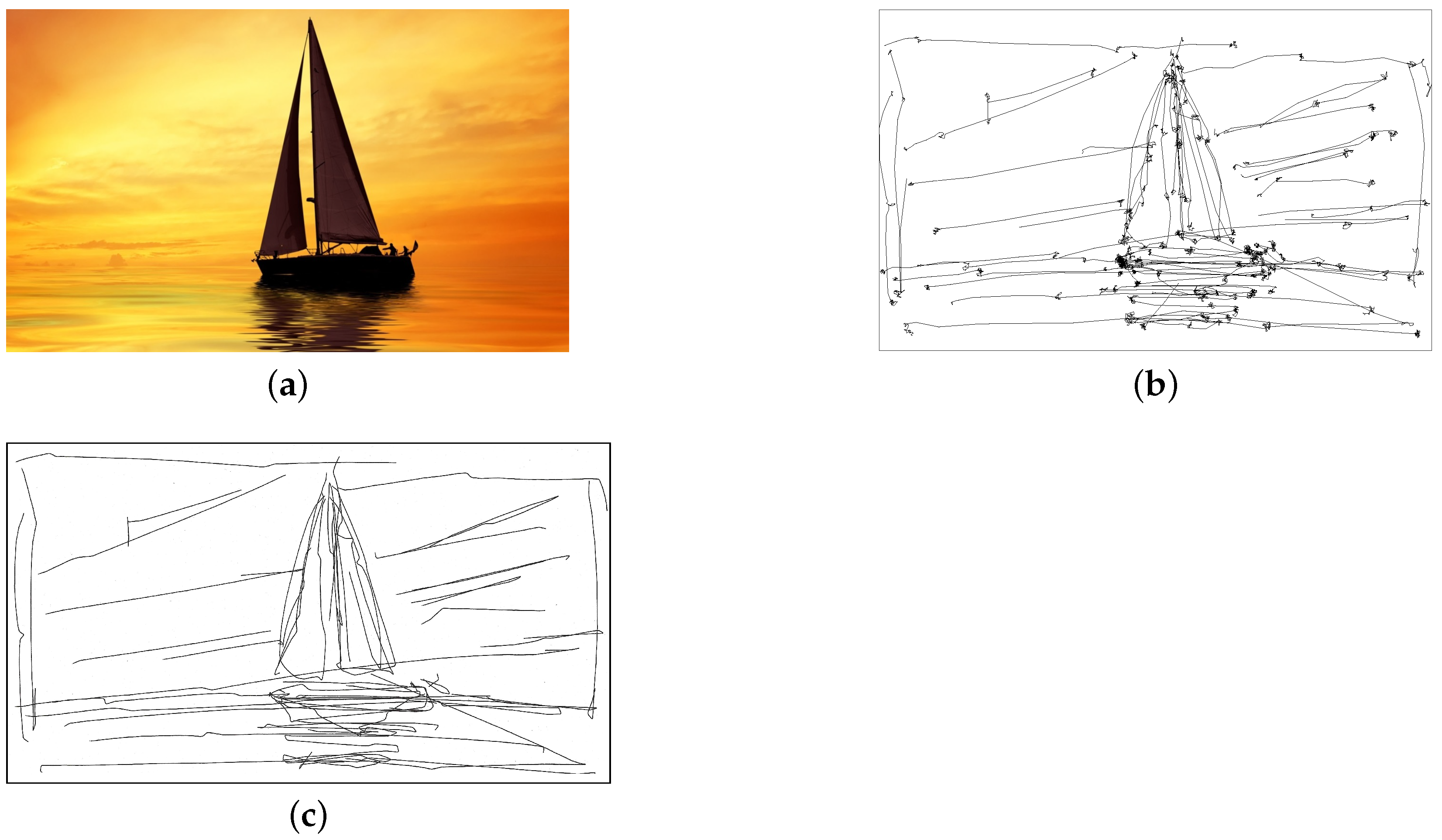
Figure 5a represents a sailboat, and
Figure 7a the map of the region Friuli-Venezia Giulia in Italy.
Figure 5b,
Figure 6b,
Figure 7b and
Figure 8b show four examples of raw images realized by the first author of this paper, who did not have a long experience with the eye tracker. In these images, saccadic eye movements and fixations can be clearly identified.
Figure 5c and
Figure 6c represent the images drawn by the robot starting from the raw data of
Figure 5b and
Figure 6b, respectively. Before the robot drawing, the raw data have been filtered and processed to remove the agglomerates of points given by the fixations and to smooth them so as to obtain feasible paths for the robot.
Figure 7c and
Figure 8c report the images drawn by the robot starting from the raw data of
Figure 7b and
Figure 8b. In this case, the algorithm for the area filling has been applied to cover some areas of the images with a texture of parallel lines with random perturbations. As it can be seen from the images, the strokes obtained from the eye tracker often deviate from the main contours of the image. Indeed, the quality of the results mainly depends on the eye tracker calibration and on the ability of the user to track the image without moving his/her head and introducing involuntary eye movements during the process of painting with eyes. However, the results show the feasibility of the proposed architecture and painting system with great ease of use.
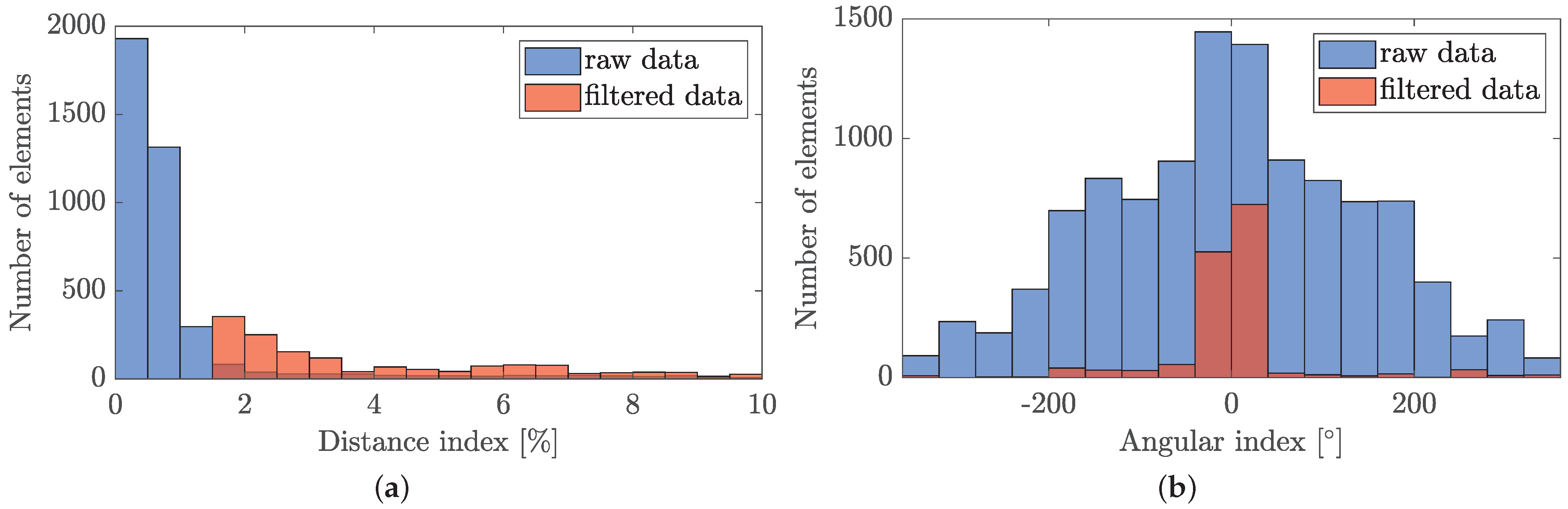
To analyze the images drawn with the proposed system before and after the removal of the fixations, two quantitative metrics have been introduced: the distance index and the angular index. The former accounts for the Euclidean distance
between each couple of consecutive points
and
in a stroke, as illustrated in
Figure 9. It is measured as a percentage value relative to the height of the image. The latter represents the difference
between the angular orientations
and
of two consecutive line segments, where
.
Figure 10,
Figure 11,
Figure 12 and
Figure 13 report the histograms for the distance index and the angular index for the test images of
Figure 5,
Figure 6,
Figure 7 and
Figure 8. In the histograms, the indexes relative to the raw data are compared with the results obtained with the filtered data. As it can be seen, the raw data show a high number of very small distances between points. Moreover, the angular variations between consecutive segments, represented by the angular index, are distributed over a wide range of values. These facts can be explained since the presence of fixations is responsible for small distance between points, and sudden changes in direction between one segment and the next. On the other hand, filtered data do not show small values of the distance index, and the angular index is mainly limited to the range
. This results from the elimination of the fixations, which provides smoother strokes and more evenly spaced points.
These considerations are supported by the values of mean and standard deviation of the distance and angular index reported in
Table 1, where the standard deviation measures the amount of variation or dispersion of the set of values. From the table it can be seen that, switching from raw to filtered data, the mean distance index increases and the standard deviation of the angular index decreases. For example, for the test image 1 (first row of
Table 1) the mean of the distance index is equal to 1.28 for the raw data and becomes equal to 4.27 for the filtered data. On the other hand, the standard deviation of the angular index, which mean is close to zero, switches from 143.4 to 77.6, showing that most of the filtered values fall between −76.6
and 78.6
. This indicates that the values of the processed data of the angular index tend to be closer to the mean of the set with respect to the raw data, resulting in strokes with less pronounced changes of angular variation, as expected after the application of the filter.
7. Conclusions
In this paper, we presented a novel architecture for controlling an industrial robot via eye tracking interface for artistic purposes. A human–robot interaction has been achieved thanks to an acquisition system based on an eye tracker device that allows the user to control the motion of the robotic manipulator with his gaze. Data from the eye tracker are filtered and processed before being sent to the robotic manipulator that reproduces the resulting path on the painting surface. An algorithm for the filling of large areas has been as well implemented to allow the user to paint regions previously defined interactively with the gaze. The feasibility of the robotic system has been evaluated with experimental tests in which the robot is teleoperated with the gaze to draw artistic images.
Future developments of this work will include the improvements of the present techniques for the gaze data filtering and processing. Additional effort will be dedicated to the implementation of other human–machine interfaces for the control of the start and stop of the eye tracker acquisition. These could be based for example on a voice recognition system or a head tracker device, instead of being linked to the pressing of a key on the keyboard. This will be beneficial especially for users who have movement disorders. Furthermore, we will develop artificial intelligence techniques to obtain more aesthetically pleasing artistic results from the gaze data.
In future developments of this work, we will also apply further quantitative metrics to estimate the quality of the results and to demonstrate how the system works and how easily it can be learned. In particular, naïve participants could be shown a set of shapes or silhouettes and asked to recreate these using the system. Then, the generated paintings could be quantitatively compared to the original silhouettes (e.g., via Hausdorff distance, procrustes analysis, structural similarity index). The training process could also be studied by comparing the reconstruction errors in different consecutive trials. Finally, the proposed robotic system will be tested by patients with movement disorders of muscular paralysis, as an assistive technology for artistic drawing or painting.
Author Contributions
Conceptualization, P.G.; methodology, software, validation, formal analysis, investigation, L.S. and P.G.; resources, data curation, L.S., S.S., and P.G.; writing—original draft preparation, L.S. and S.S.; writing—review and editing, L.S., S.S., and M.L.; supervision and project administration, P.G. and A.G. All authors have read and agreed to the published version of the manuscript.
Funding
This research received no external funding.
Institutional Review Board Statement
Not applicable.
Informed Consent Statement
Not applicable.
Data Availability Statement
Not applicable.
Acknowledgments
The authors thank Davide Ronzat for his help in the configuration of the experimental setup.
Conflicts of Interest
The authors declare no conflict of interest.
References
- Majaranta, P.; Bulling, A. Eye tracking and eye-based human–computer interaction. In Advances in Physiological Computing; Springer: Berlin, Germany, 2014; pp. 39–65. [Google Scholar]
- Pasqualotto, E.; Matuz, T.; Federici, S.; Ruf, C.A.; Bartl, M.; Olivetti Belardinelli, M.; Birbaumer, N.; Halder, S. Usability and workload of access technology for people with severe motor impairment: A comparison of brain-computer interfacing and eye tracking. Neurorehabilit. Neural Repair 2015, 29, 950–957. [Google Scholar] [CrossRef] [PubMed]
- Orquin, J.L.; Holmqvist, K. Threats to the validity of eye-movement research in psychology. Behav. Res. Methods 2018, 50, 1645–1656. [Google Scholar] [CrossRef] [PubMed] [Green Version]
- dos Santos, R.D.O.J.; de Oliveira, J.H.C.; Rocha, J.B.; Giraldi, J.D.M.E. Eye tracking in neuromarketing: A research agenda for marketing studies. Int. J. Psychol. Stud. 2015, 7, 32. [Google Scholar] [CrossRef]
- Corcoran, P.M.; Nanu, F.; Petrescu, S.; Bigioi, P. Real-time eye gaze tracking for gaming design and consumer electronics systems. IEEE Trans. Consum. Electron. 2012, 58, 347–355. [Google Scholar] [CrossRef] [Green Version]
- Maimon-Mor, R.O.; Fernandez-Quesada, J.; Zito, G.A.; Konnaris, C.; Dziemian, S.; Faisal, A.A. Towards free 3D end-point control for robotic-assisted human reaching using binocular eye tracking. In Proceedings of the 2017 International Conference on Rehabilitation Robotics (ICORR), London, UK, 17–20 July 2017; pp. 1049–1054. [Google Scholar]
- Schiatti, L.; Tessadori, J.; Barresi, G.; Mattos, L.S.; Ajoudani, A. Soft brain-machine interfaces for assistive robotics: A novel control approach. In Proceedings of the 2017 International Conference on Rehabilitation Robotics (ICORR), London, UK, 17–20 July 2017; pp. 863–869. [Google Scholar]
- Wang, Y.; Zeng, H.; Song, A.; Xu, B.; Li, H.; Zhu, L.; Wen, P.; Liu, J. Robotic arm control using hybrid brain-machine interface and augmented reality feedback. In Proceedings of the 2017 8th International IEEE/EMBS Conference on Neural Engineering (NER), Shanghai, China, 25–28 May 2017; pp. 411–414. [Google Scholar]
- Wöhle, L.; Gebhard, M. Towards Robust Robot Control in Cartesian Space Using an Infrastructureless Head-and Eye-Gaze Interface. Sensors 2021, 21, 1798. [Google Scholar] [CrossRef]
- Gips, J.; Olivieri, P. EagleEyes: An eye control system for persons with disabilities. In Proceedings of the Eleventh International Conference on Technology and Persons with Disabilities, Los Angeles, CA, USA, 4–6 March 1996; Volume 1. [Google Scholar]
- Van der Kamp, J.; Sundstedt, V. Gaze and voice controlled drawing. In Proceedings of the 1st Conference on Novel Gaze-Controlled Applications, Karlskrona, Sweden, 26–27 May 2011; pp. 1–8. [Google Scholar]
- Heikkilä, H. Tools for a Gaze-Controlled Drawing Application–Comparing Gaze Gestures against Dwell Buttons. In IFIP Conference on Human-Computer Interaction; Springer: Berlin, Germany, 2013; pp. 187–201. [Google Scholar]
- Santella, A.; DeCarlo, D. Abstracted painterly renderings using eye-tracking data. In Proceedings of the 2nd International Symposium on Non-Photorealistic Animation and Rendering, Annecy, France, 3–5 June 2002; pp. 75–82. [Google Scholar]
- Graham Fink. Eye Drawings. 2020. Available online: https://grahamfink.com/eye-drawings (accessed on 26 January 2021).
- Bradley, J.P. The Delirious Abstract Machines of Jean Tinguely. In Ecosophical Aesthetics: Art, Ethics and Ecology with Guattari; Bloomsbury Publishing: London, UK, 2018; pp. 193–216. [Google Scholar]
- Cohen, H. The further exploits of AARON, painter. Stanf. Humanit. Rev. 1995, 4, 141–158. [Google Scholar]
- Tresset, P.; Leymarie, F.F. Portrait drawing by Paul the robot. Comput. Graph. 2013, 37, 348–363. [Google Scholar] [CrossRef]
- Gülzow, J.M.; Paetzold, P.; Deussen, O. Recent Developments Regarding Painting Robots for Research in Automatic Painting, Artificial Creativity, and Machine Learning. Appl. Sci. 2020, 10, 3396. [Google Scholar] [CrossRef]
- Igno-Rosario, O.; Hernandez-Aguilar, C.; Cruz-Orea, A.; Dominguez-Pacheco, A. Interactive system for painting artworks by regions using a robot. Robot. Auton. Syst. 2019, 121, 103263. [Google Scholar] [CrossRef]
- Karimov, A.I.; Kopets, E.E.; Rybin, V.G.; Leonov, S.V.; Voroshilova, A.I.; Butusov, D.N. Advanced tone rendition technique for a painting robot. Robot. Auton. Syst. 2019, 115, 17–27. [Google Scholar] [CrossRef]
- Scalera, L.; Seriani, S.; Gasparetto, A.; Gallina, P. Watercolour robotic painting: A novel automatic system for artistic rendering. J. Intell. Robot. Syst. 2019, 95, 871–886. [Google Scholar] [CrossRef]
- Scalera, L.; Seriani, S.; Gasparetto, A.; Gallina, P. Busker Robot: A robotic painting system for rendering images into watercolour artworks. In IFToMM Symposium on Mechanism Design for Robotics; Springer: Berlin, Germany, 2018; pp. 1–8. [Google Scholar]
- Beltramello, A.; Scalera, L.; Seriani, S.; Gallina, P. Artistic Robotic Painting Using the Palette Knife Technique. Robotics 2020, 9, 15. [Google Scholar] [CrossRef] [Green Version]
- Guo, C.; Bai, T.; Lu, Y.; Lin, Y.; Xiong, G.; Wang, X.; Wang, F.Y. Skywork-daVinci: A novel CPSS-based painting support system. In Proceedings of the 16th International Conference on Automation Science and Engineering (CASE), Hong Kong, China, 20–21 August 2020; pp. 673–678. [Google Scholar]
- Bidgoli, A.; De Guevara, M.L.; Hsiung, C.; Oh, J.; Kang, E. Artistic Style in Robotic Painting; a Machine Learning Approach to Learning Brushstroke from Human Artists. In Proceedings of the 2020 29th IEEE International Conference on Robot and Human Interactive Communication (RO-MAN), Naples, Italy, 31 August–4 September 2020; pp. 412–418. [Google Scholar]
- Santos, M.; Notomista, G.; Mayya, S.; Egerstedt, M. Interactive Multi-Robot Painting Through Colored Motion Trails. Front. Robot. AI 2020, 7, 143. [Google Scholar] [CrossRef] [PubMed]
- Gatys, L.A.; Ecker, A.S.; Bethge, M. Image style transfer using convolutional neural networks. In Proceedings of the IEEE Conference on Computer Vision and Pattern Recognition, Las Vegas, NV, USA, 26 June–1 July 2016; pp. 2414–2423. [Google Scholar]
- Scalera, L.; Seriani, S.; Gasparetto, A.; Gallina, P. Non-photorealistic rendering techniques for artistic robotic painting. Robotics 2019, 8, 10. [Google Scholar] [CrossRef] [Green Version]
- Karimov, A.; Kopets, E.; Kolev, G.; Leonov, S.; Scalera, L.; Butusov, D. Image Preprocessing for Artistic Robotic Painting. Inventions 2021, 6, 19. [Google Scholar] [CrossRef]
- Quintero, C.P.; Dehghan, M.; Ramirez, O.; Ang, M.H.; Jagersand, M. Flexible virtual fixture interface for path specification in tele-manipulation. In Proceedings of the 2017 IEEE International Conference on Robotics and Automation (ICRA), Singapore, 29 May–3 June 2017; pp. 5363–5368. [Google Scholar]
- Tramonte, S.; Sorbello, R.; Guger, C.; Chella, A. Acceptability Study of A3-K3 Robotic Architecture for a Neurorobotics Painting. Front. Neurorobot. 2019, 12, 81. [Google Scholar] [CrossRef] [PubMed] [Green Version]
- Scalera, L.; Seriani, S.; Gasparetto, A.; Gallina, P. A Novel Robotic System for Painting with Eyes. Mech. Mach. Sci. 2021, 91, 191–199. [Google Scholar] [CrossRef]
- Yarbus, A.L. Eye movements during perception of complex objects. In Eye Movements and Vision; Springer: Berlin, Germany, 1967; pp. 171–211. [Google Scholar]
- Carpenter, R.H. Movements of the Eyes, 2nd ed.; Pion Limited: London, UK, 1988. [Google Scholar]
- Land, M.; Tatler, B. Looking and Acting: Vision and Eye Movements in Natural Behaviour; Oxford University Press: Oxford, UK, 2009. [Google Scholar]
- Rayner, K. The 35th Sir Frederick Bartlett Lecture: Eye movements and attention in reading, scene perception, and visual search. Q. J. Exp. Psychol. 2009, 62, 1457–1506. [Google Scholar] [CrossRef] [PubMed]
- Young, L.R.; Sheena, D. Survey of eye movement recording methods. Behav. Res. Methods Instrum. 1975, 7, 397–429. [Google Scholar] [CrossRef]
- Gibaldi, A.; Vanegas, M.; Bex, P.J.; Maiello, G. Evaluation of the Tobii EyeX Eye tracking controller and Matlab toolkit for research. Behav. Res. Methods 2017, 49, 923–946. [Google Scholar] [CrossRef] [PubMed] [Green Version]
- Biagiotti, L.; Melchiorri, C. Trajectory Planning for Automatic Machines and Robots; Springer: Berlin, Germany, 2008. [Google Scholar]
- This Person Does Not Exist. 2020. Available online: https://www.thispersondoesnotexist.com/ (accessed on 26 January 2021).
| Publisher’s Note: MDPI stays neutral with regard to jurisdictional claims in published maps and institutional affiliations. |
© 2021 by the authors. Licensee MDPI, Basel, Switzerland. This article is an open access article distributed under the terms and conditions of the Creative Commons Attribution (CC BY) license (http://creativecommons.org/licenses/by/4.0/).


 ,
, 


