A Review of Active Hand Exoskeletons for Rehabilitation and Assistance


Abstract
:1. Introduction
2. Method
2.1. Inclusion and Exclusion Criteria
2.1.1. Inclusion Criteria
- The device described was a wearable active device that had some sort of actuating unit for delivering the appropriate range of motion (ROM) for the hand.
- The paper is accessible to the authors and is a scientific article written in the English language.
- The study presented the mechanical and electrical aspects of the designed hand exoskeleton in four of the following attributes: active degree of freedom (DOF), output force, intended action, ROM, weight, or control methods.
- The device actuates at least one finger actively.
- The device is intended for rehabilitation or assistive purposes.
2.1.2. Exclusion Criteria
- The device was intended for other body parts or limbs other than the hands.
- The device was a prosthetic or anthropomorphic hand for lost limbs.
- The paper or article was published in any language other than English.
- The study had insufficient information on the design, which made the analysis unclear.
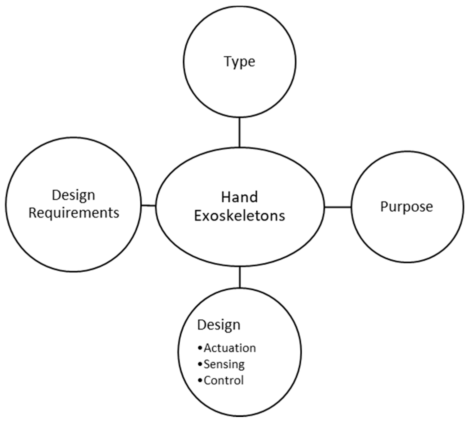
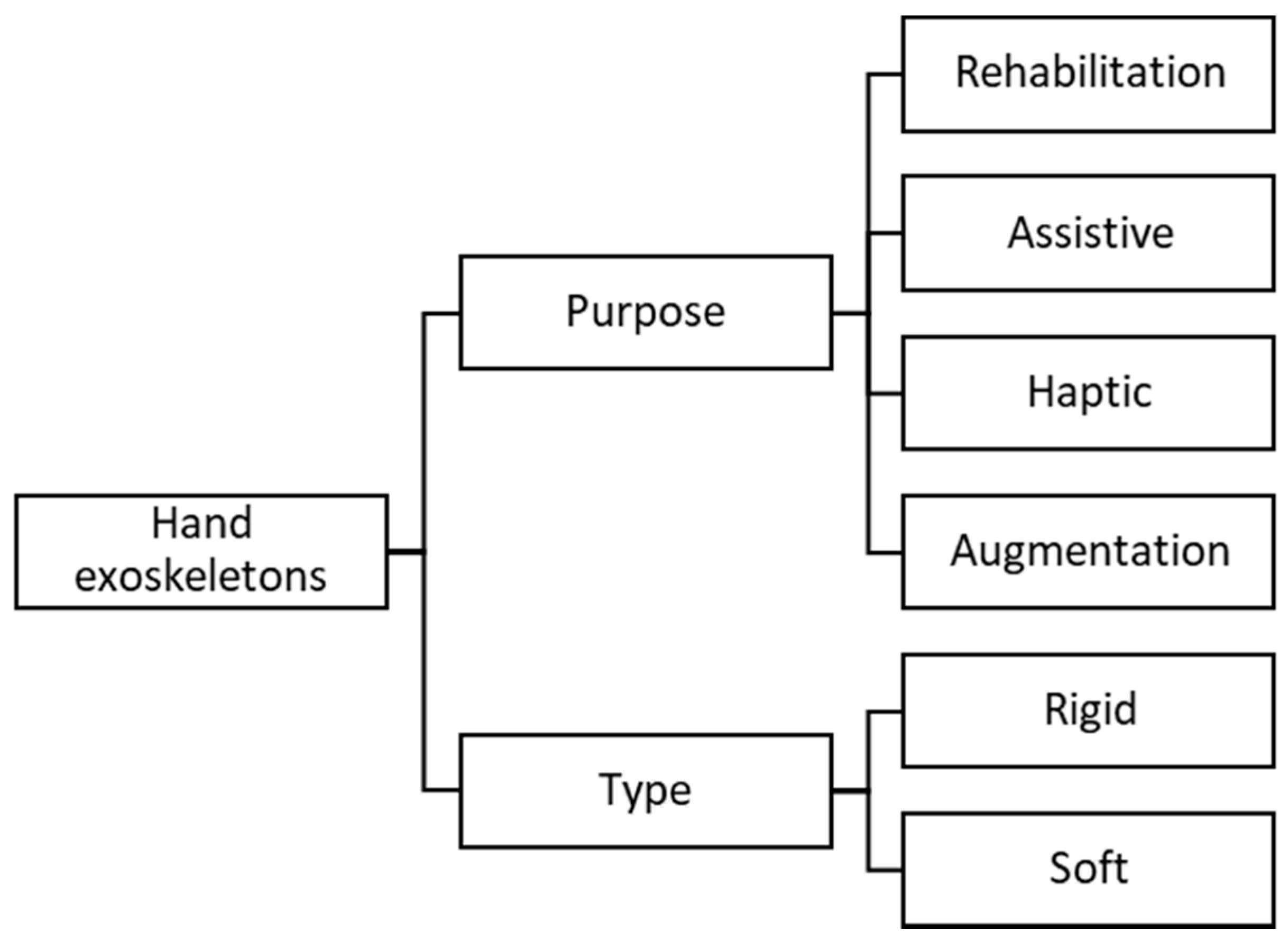
2.2. Framework
3. Hand Anatomy and Biomechanics
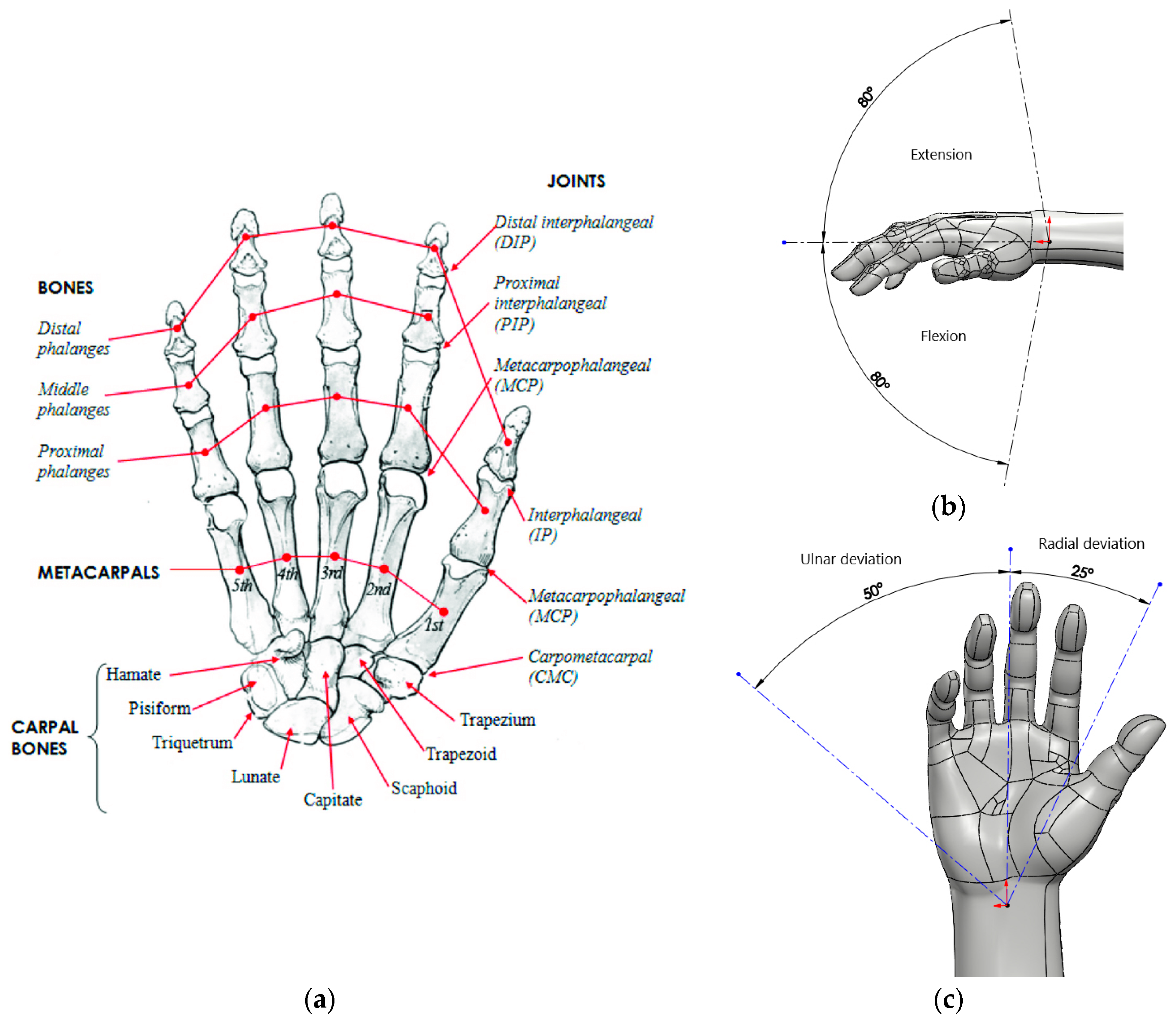
3.1. Bones and Joints
3.1.1. The Wrist (Carpus)
3.1.2. The Palm (Metacarpus)
3.1.3. The Fingers (Phalanges)
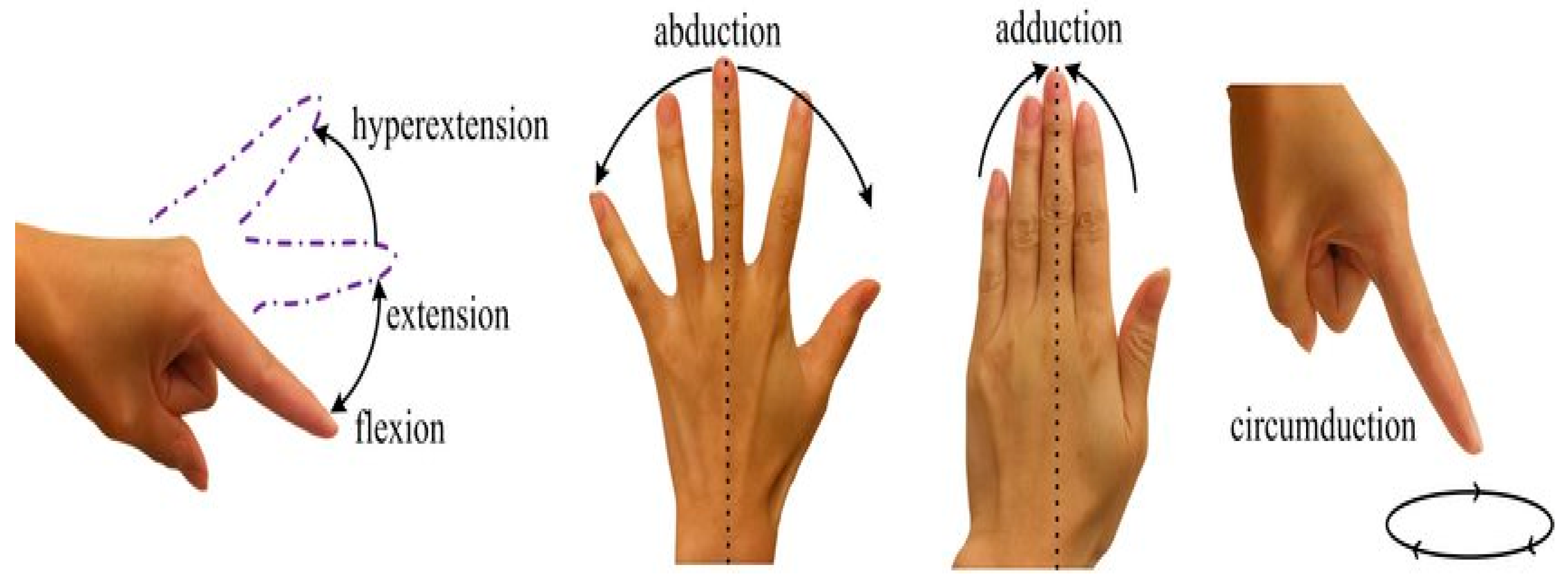
3.1.4. Joints (Articulations)
- MCP joints: Flexion approximately 90°, extension approximately 40°, abduction approximately 15° and adduction approximately 15°
- PIP joints: Flexion approximately 130°, extension approximately 0°
- DIP joints: Flexion approximately 90°, extension approximately 30°
3.1.5. The Thumb
- The opposition.
- The coordinated movement between the thumb, index, and middle finger.
- The little and ring finger as a strengthening unit of the fist.
3.1.6. Movement of the Thumb
- Approximately 35° abduction and 25° adduction
- Approximately 25° flexion and 45° extension
- Approximately 10° rotation in CMC joint
3.2. Muscles
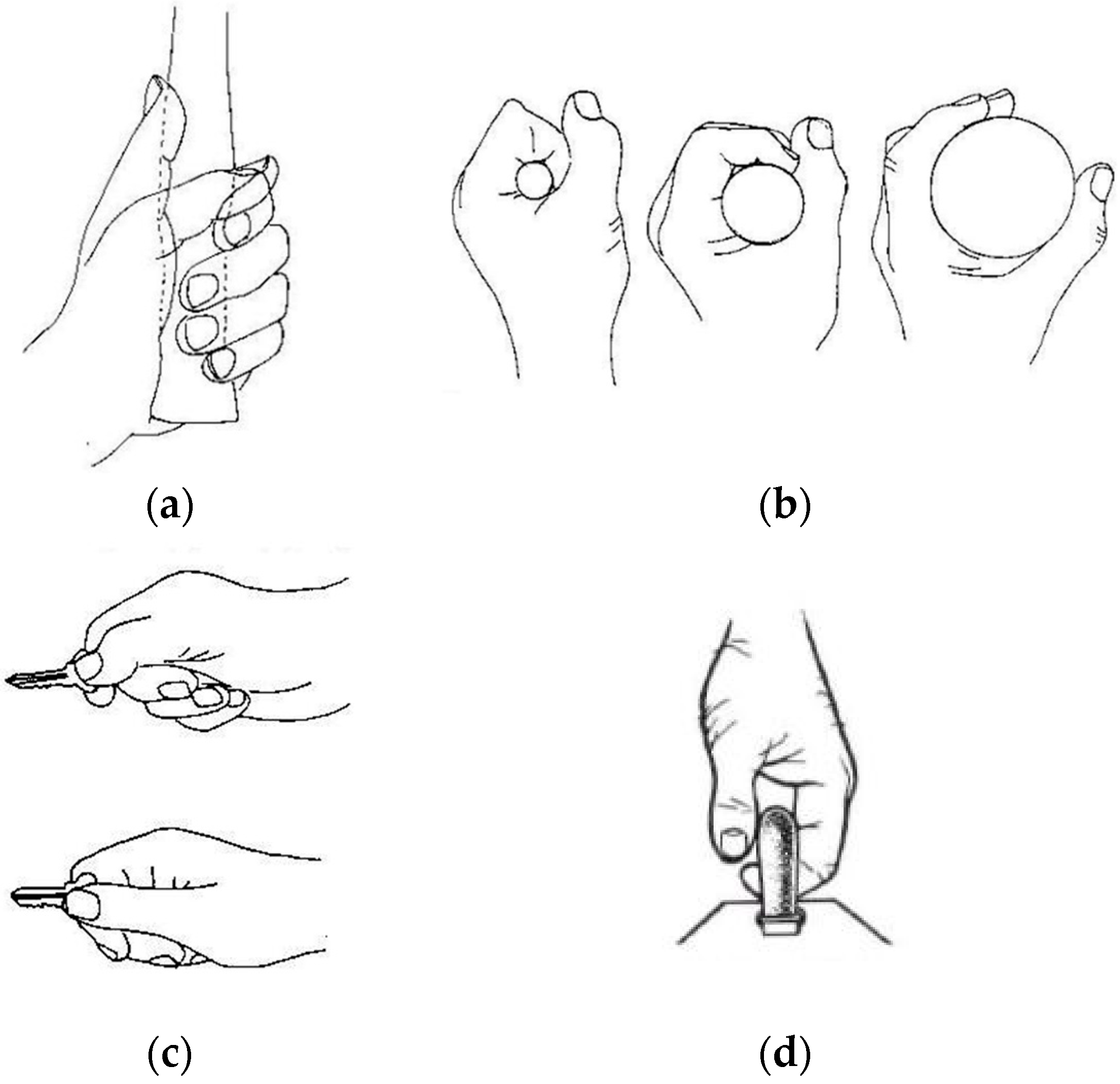
3.3. Overall Types of Hand Grips
- Power grip indicates that the object is clamped between the partly flexed fingers and the palm. The thumb applies counter pressure, which lies in the plane of the palm. Different forms of a power grip exist such as where the thumb is opposed rather than adducted to grasp an object such as a class or bottle (cylindrical grasp) (Figure 4a,b).
- Precision grip is when the object may be pinched between the fingertips and opposed thumb. Many grips have also been identified such as the tip-to-tip, tip-to-pad, key grip, tripod grip (for holding a pen), etc. (Figure 4c).
- Hook grip forms part of the power grip family but is different in the sense that the thumb is rarely used. This grip has the fingers fully flexed to form a hook in the palm. This is useful when precision is not a requirement and where power needs to be exerted over longer periods such as holding a suitcase or a shopping bag (Figure 4d).
4. Basic Requirements for Hand Exoskeletons
4.1. General Requirements
4.1.1. Safety
4.1.2. Comfort
4.1.3. Affordability
4.1.4. Adaptability
4.2. Specific Requirements
4.2.1. Rehabilitation
4.2.2. Assistive
4.2.3. Haptic
4.2.4. Augmentation
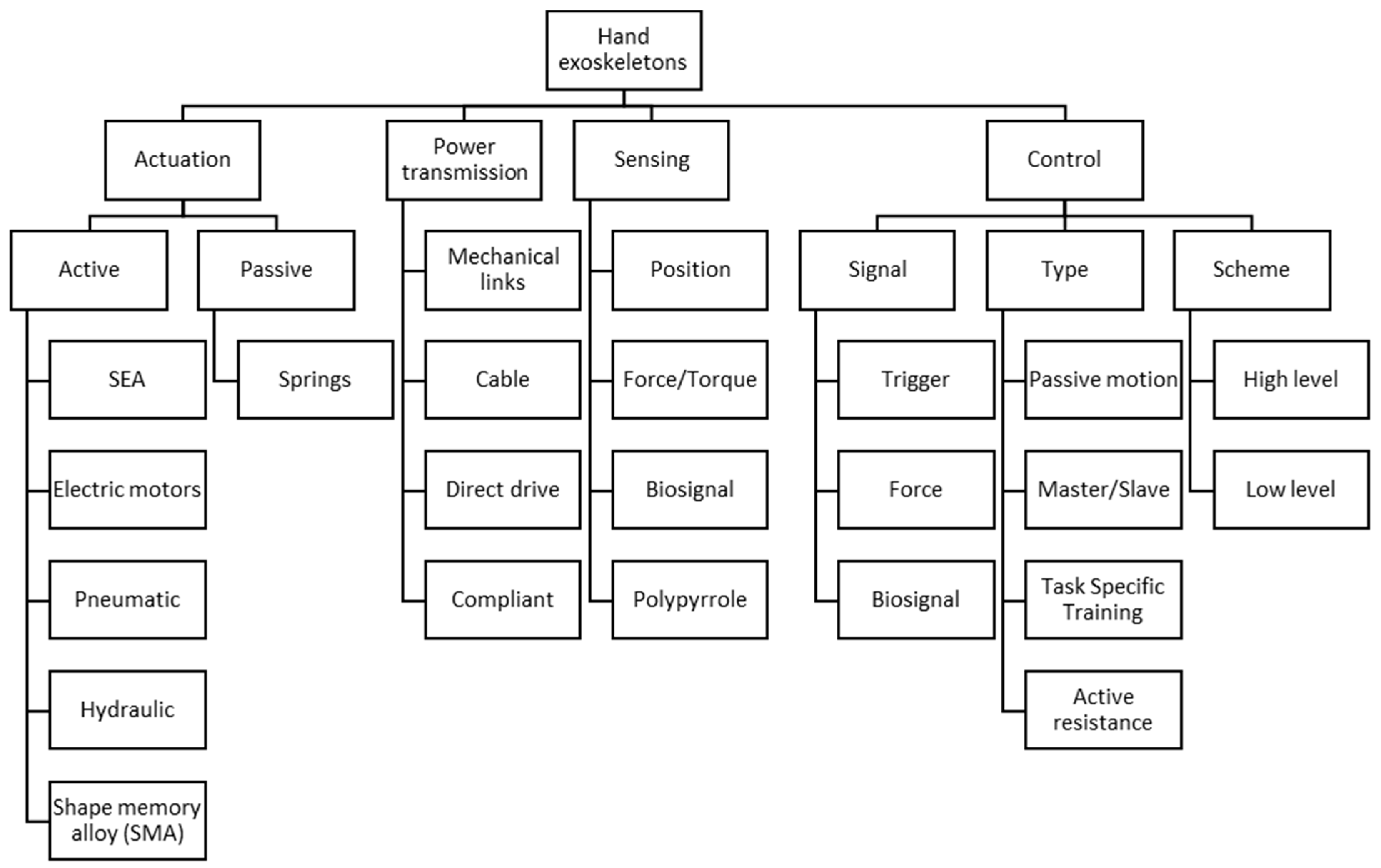
5. Overview of Hand Exoskeleton Technologies
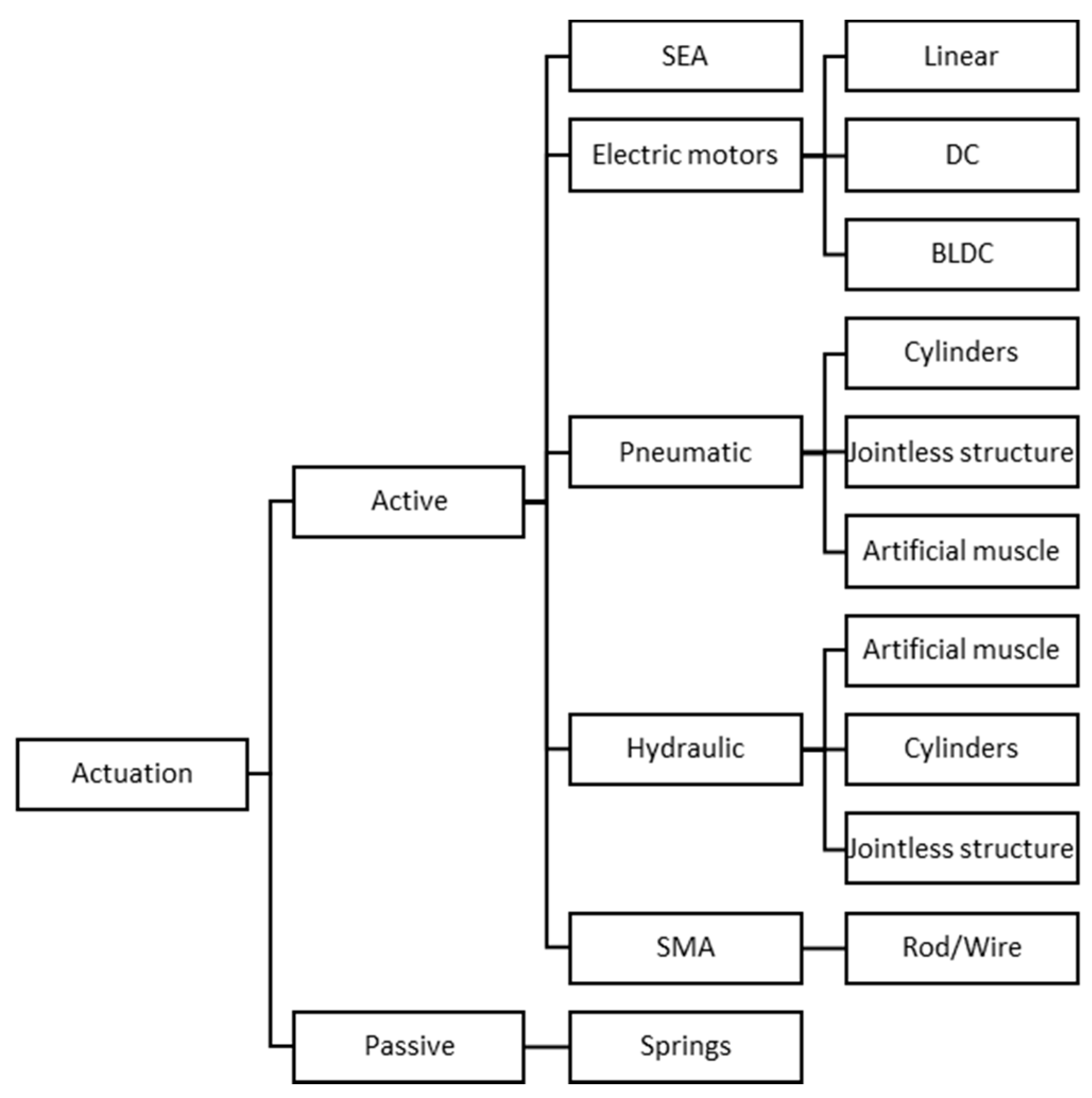
5.1. Actuation
5.1.1. Passive Actuation
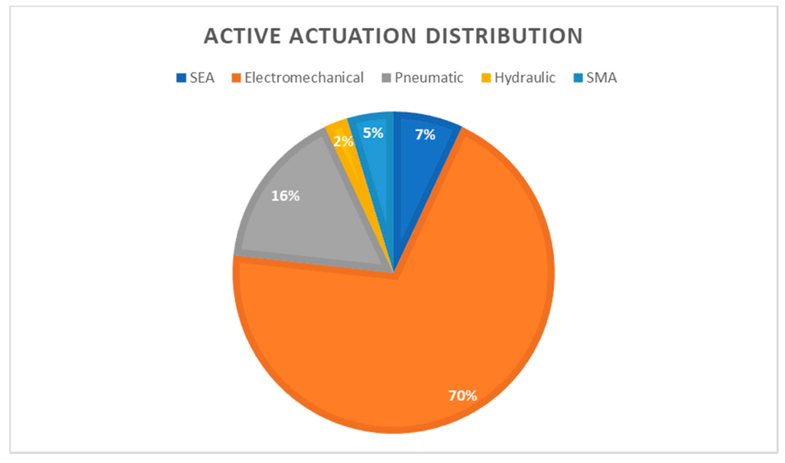
5.1.2. Active Actuation
- Electric Motors: This is one of the most widely used and popular methods of actuating exoskeletons in general (Figure 11). There are many varieties found in the literature such as DC motors, Brushless DC (BLDC) motors, linear actuators, and servo motors (Figure 10). DC motors are known for their simplicity, easy to control, low cost, and backdrivability, but they suffer from high maintenance due to the wear of the brushes, in contact with the commutator, and low torque at high speeds. This requires the motor to be connected to a reduction (gears, pulleys, lead screws, etc.) unit to increase the torque, but this will reduce the operating speed of the motor. Devices such as [31,32,38,41,43,44,47,48,56,57,59,61,62,63,65,69,70,74,85,86,87] all contain DC motors, and it includes servo motors. Servo motors are essentially geared DC motors with limited rotation, which are commonly driven by pulse width modulation (PWM) signals. The servomotors used in these hand exoskeleton prototyping are usually hobby-grade motors. Linear actuators are most of the time DC motors connected to a lead screw assembly to convert the rotational motion of the motor to linear motion. This motion is preferred in many rigid hand exoskeletons because the four-bar linkage system can be “pushed or pulled” to flex or extent the fingers as per the design and limits the ROM. This can be seen in devices such as [35,37,40,42,58,66,67,68,72]. BLDC is a motor that is part of the AC family (more specifically of a synchronous, permanent magnet type). It might not seem that way, but these types of motors are much better than DC motors regarding noise, size, efficiency, maintenance, etc. (Table 3), just to name a few. The BLDC motor uses an electronic inverter instead of a commutator and brushes to achieve rotation. Devices such as [76,88] make use of the BLDC motor for actuation.
- Pneumatic actuators: this method of actuating the fingers of the hand is the next most popular method of exploration (Figure 11). Pneumatic actuation refers to the use of compressed air to execute the required action. Various methods have been developed to acquire the ROM of the fingers by the use of inflatable flexible materials [51,52], pneumatic cylinders [60,89], bellow-shaped systems [53], or artificial muscles [45,54,90]. Some pneumatic cylinders are directly connected to the required phalanges. This means that these devices are usually situated in the palm as in [89], whereas most of the other systems are located at the dorsal side of the hand. Pneumatic systems are also used for augmentation purposes but work for rehabilitation and assistance as well. A pneumatic driven glove has the advantage of being lightweight on the hand itself as well as have a high power to weight ratio, but this system has a few drawbacks for use in assistive situations. Pneumatic systems require a compressor, storage tank, valves, transport air tubes, etc. This can cause the system to become bulky and heavy. According to Boser et al. [55], patients with hand impairments have indicated that a waist belt containing this equipment that weighs less than 3kg will be acceptable, but in general, this equipment can be on the heavy side depending on the pressure and size required. Therefore, remote actuation is recommended for this actuator or with the use of a wheelchair where the equipment can be stored.
- Hydraulic actuators: This method of actuation is similar to the pneumatic system in operation, but instead of air, an incompressible liquid is used. This is for applications where generally more power is required; therefore, it is suitable for use in augmentation devices. Hydraulic cylinders [60], flexible inflatable materials [50], as well as certain artificial muscles [45,54] are devices that are explored to transfer hydraulic power.
- Series Elastic Actuators (SEA): SEA is a system that can be driven by an electric motor but utilizes a spring element in series with the load, which creates certain unique features. The traditional aim of joints is to be as stiff as possible, but in the case of SEAs, the aim is to reduce the stiffness of the joint, which creates new possibilities. SEAs offer several advantages such as greater shock absorbance, lower reflected inertia, more accurate and stable force control, and the most important one is the increase in safety due to the lower stiffness [90]. This actuator seems to be an ideal solution for hand exoskeletons, but the reduction in joint or actuator stiffness means that lower forces can be transferred to the exoskeleton. It also increases the mechanical complexity of the device, has higher power requirements, and has a low actuation bandwidth. Very few researchers have implemented this type of actuator over the years such as [42,61,65,69].
- Shape Memory Alloy (SMA): This type of actuator was explored by [39,49]. It is an unusual type of actuator, which works on the principle of deformation of the material. The material expands and contracts due to heating and cooling at certain temperatures. The material is usually made of a rod or wire type and is heated by applying a current through it. The system is considered to be highly nonlinear and saturated but has a high power to weight ratio. The rods or wire also produce a lot of heat, and safety must be considered when this is to be used as a driving system for an exoskeleton.
- Other: There have been a few other actuators explored such as electroactive polymers and ultrasonic motors, which is an indication that the search for an ideal actuator is still being researched [91].
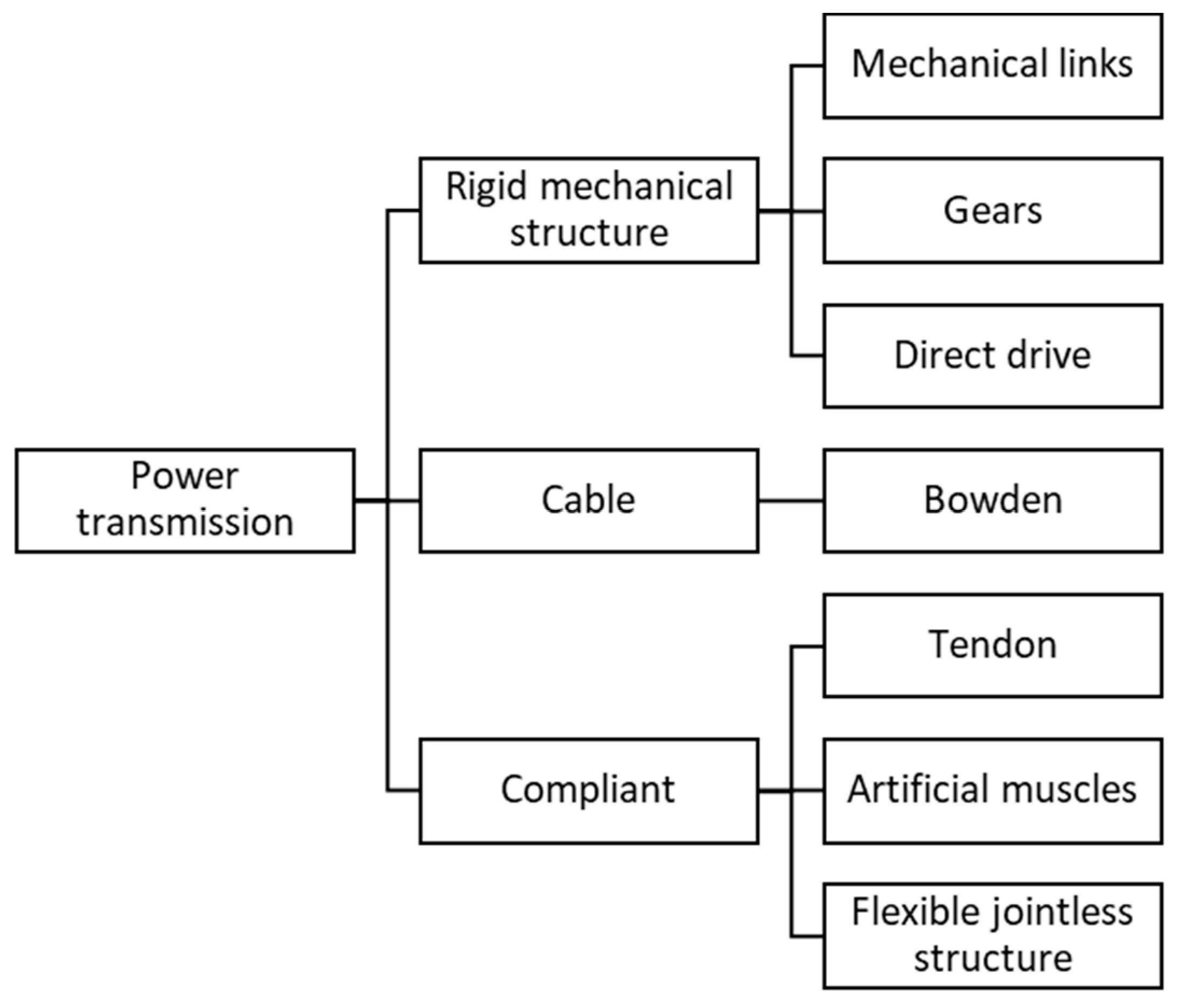
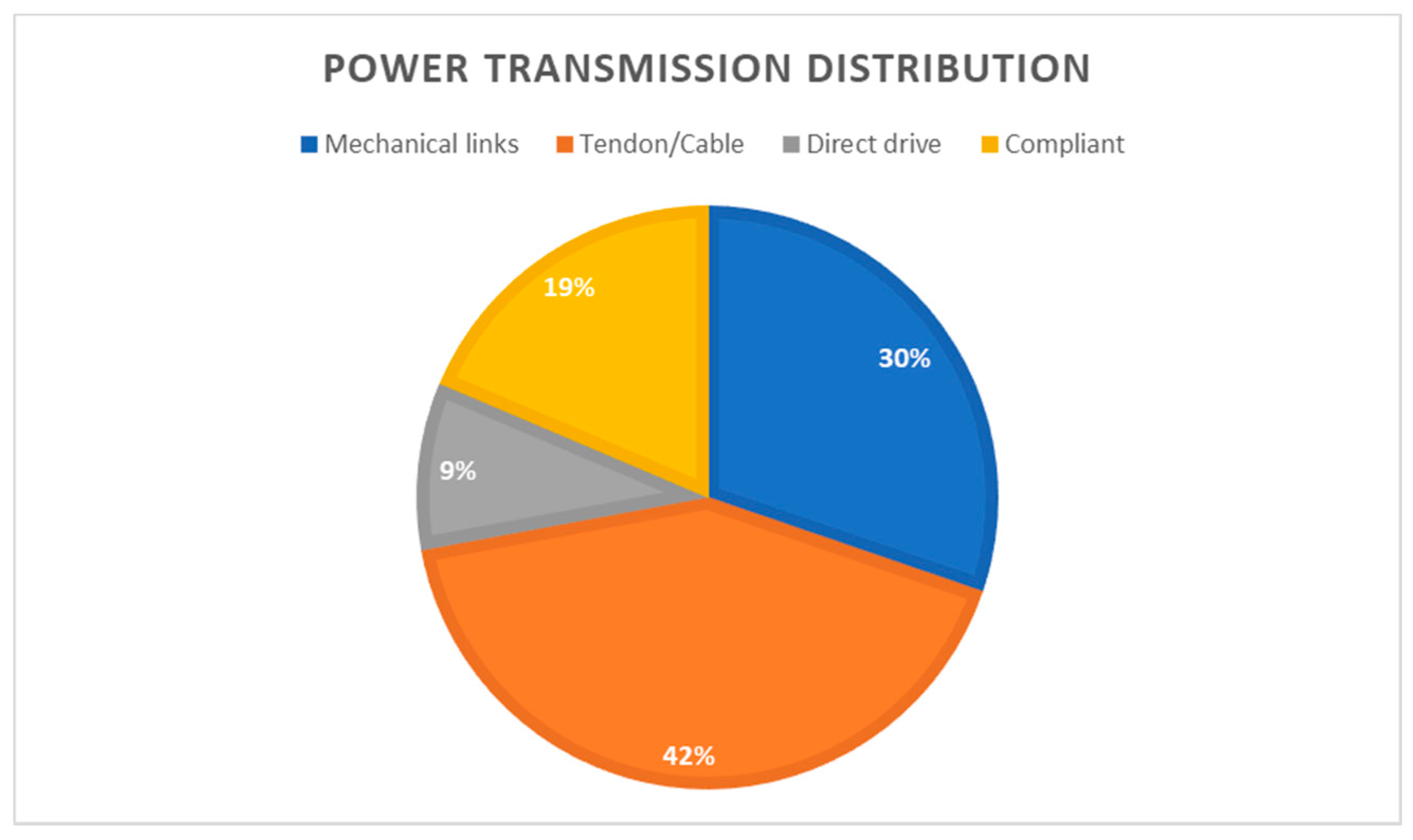
5.2. Power Transmission
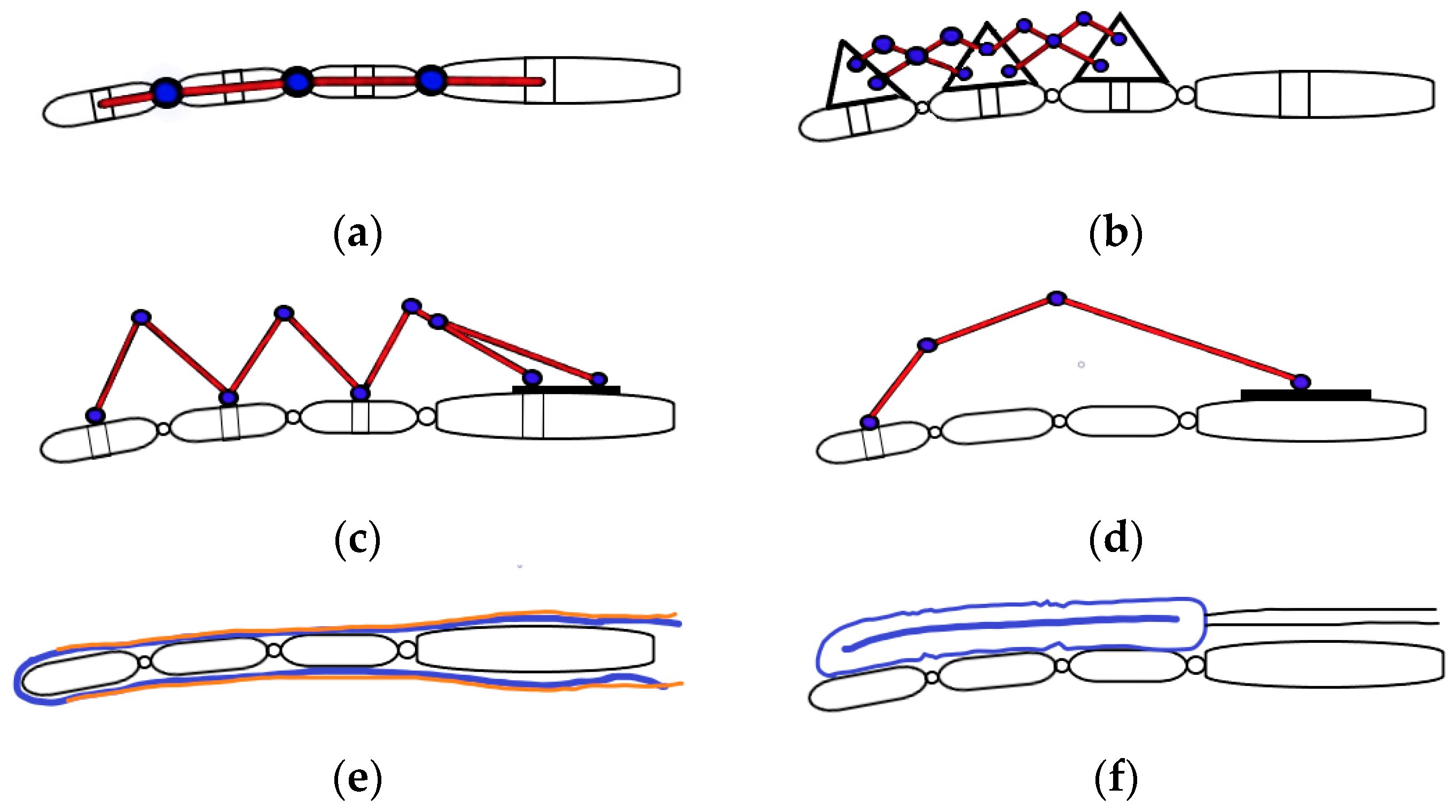
5.2.1. Rigid Mechanical Structure
5.2.2. Cable Mechanisms
5.2.3. Compliant Mechanisms
- Power is transferred to the exoskeleton via tendon cables, but the difference between tendon and Bowden cable systems is that tendon cables mimic the hand anatomy structure by flexing and extending the fingers with a cable routed in a glove, whereas Bowden cables use a rigid structure to transfer the cable forces to the fingers, as mentioned previously. Tendon cables are usually connected to the distal part of the finger and flex or extend the finger by applying tension to the cable. This type of transmission is normally unidirectional, meaning only one cable can execute a single task such as flexion or extension. A second cable is required to have a bidirectional actuation, which means another actuator is generally required. These types of developed hand exoskeletons are usually underactuated systems where a single actuator can flex or extend multiple fingers such as in [47,48,76] by the use of a single cable routed in a loop across or between the fingers. Other tendon-driven devices are usually driven by artificial muscles [45] or by SMA [49]. Tendon cables can suffer from cable breakage, the routing paths are sometimes complex and can cause power losses due to friction, but they can apply the required forces to the digit itself instead of the joints.
- Artificial muscles are another compliant way of producing finger flexion and extension. This is usually driven through compressed air (pneumatics) or liquids (hydraulics) that are injected into a flexible material surrounded by a braided sheath that contracts when inflated and vice versa [50,54]. The most popular drawback to this design is known as ballooning, where the flexible material cannot bend anymore, and due to an increase in pressure of the fluid, the material blows up like a balloon. Methods have been implemented to overcome this effect, such as the type of braiding material used to restrict the flexible material movement.
- Another type of device that was developed, similar to an artificial muscle, does not require a braided sheath to create contraction or elongation. These are known as flexible jointless structures and are made from silicone rubber molded in a specific way to bend at certain sections when inflated. This can be seen in [51,52]. Another similar approach was taken by [53], but it created bellow-shaped sections at the joints for the bending and extending motions. A different approach was taken by [58,66,68,70,86]; these types made use of a thin spring metal plate that is compressed or tensioned to flex and extend the fingers, respectively. These structures are mainly custom-designed for a user, but due to the low cost of the rubber, it is not a great concern.
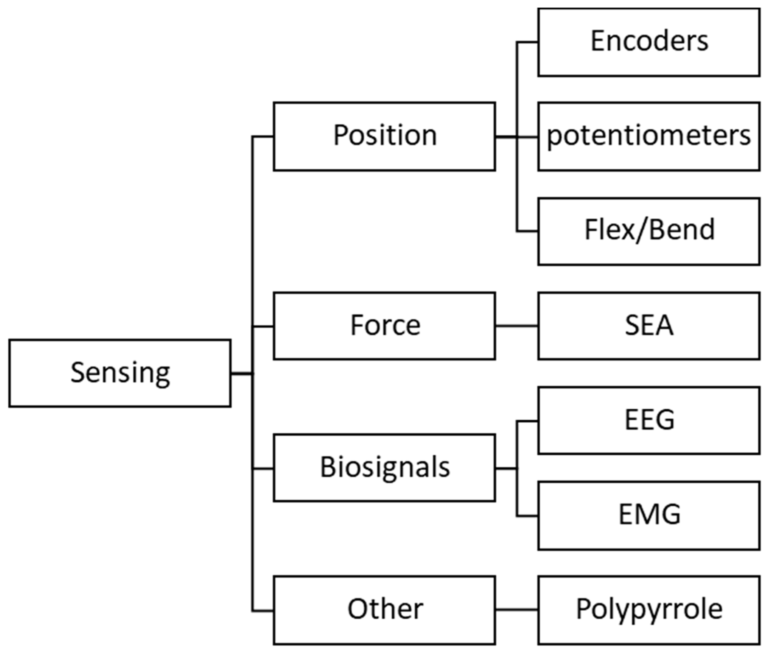
5.3. Sensing
5.3.1. Position
5.3.2. Force
5.3.3. Biosignals
5.3.4. Other
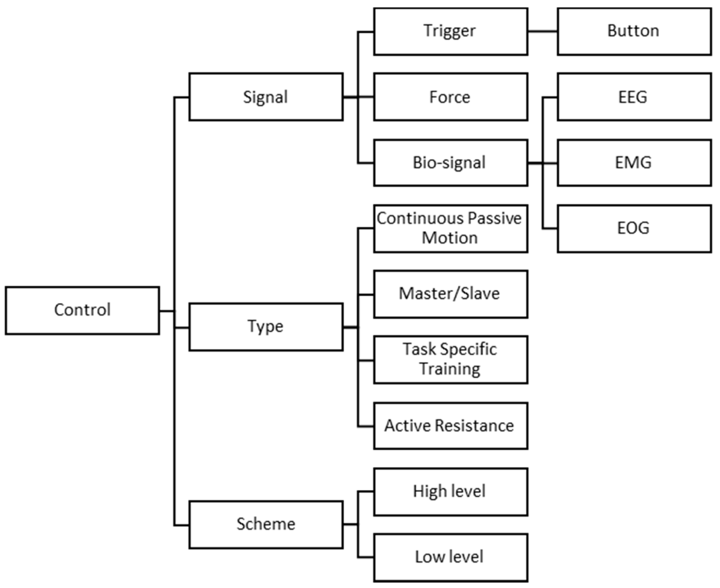
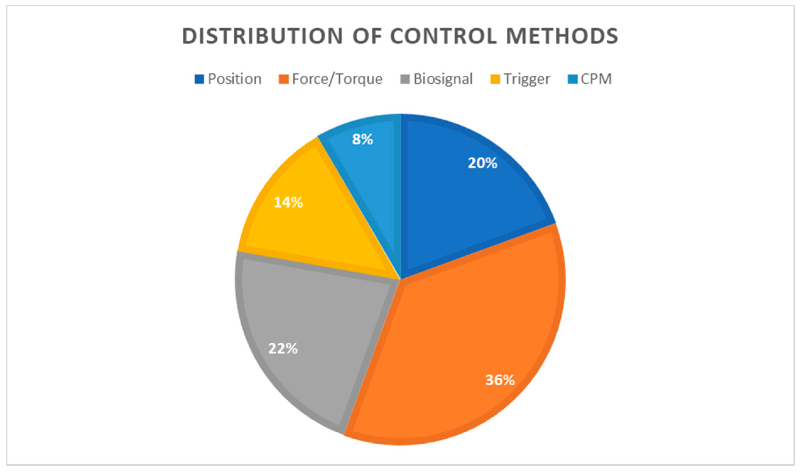
5.4. Control
5.4.1. Signals
Trigger
Force
Biosignal
- EEG: The brain sends electrical pulses to the specific muscles through nerves. These nerves carry the information to activate the specified muscle. To keep the human in control of the hand exoskeleton, an EEG can be used to measure the electrical brain activity. This electrical brain activity can be processed through a brain–computer interface (BCI) to communicate to the hand exoskeleton. This method is especially used when the user has a severe impairment, which therefore bypasses the electrical pulses to the muscles through the nerves via the BCI. Then, the BCI sends commands to the control unit of the hand exoskeleton, and tasks are executed according to the signal. The noninvasive EEG method consists of an electrode cap that is mounted on the head of the user.
- EMG: The muscles, when active, generate electrical signals that can be measured. The EMG is applied to the required area on the forearm via surface electrodes. These electrodes can measure the activity level of electrical muscle intensiveness. This control signal can be processed through various machine learning algorithms to obtain the specified threshold for certain actions to be executed.
- EOG: The EOG signal is the measure of the cornea–retina standing potential that is active between the back and front of the human eye. This signal is generally combined with the EEG signals to execute certain tasks.
5.4.2. Type
- Continuous Passive Motion (CPM): This method ignores the intentions of the user and only actuates the exoskeleton along a predefined trajectory path. There is usually no feedback to the user on progress or such because this mode of control is used for patients right after hand surgery or the initial stages of an injury to prevent the development of stiffness.
- Master/Slave: This technique requires a control glove and the exoskeleton glove. The control glove usually consists of sensors that are used as input or control signals for the exoskeleton. The control glove essentially controls the movements of the exoskeleton; in other words, the exoskeleton mimics the motions of the control glove. This technique is used for rehabilitation purposes to keep the patient in the loop of control by interacting with the device. Two hands are usually required for operation: one healthy hand to rehabilitate the impaired hand. This method is recommended for patients with hemiplegia.
- Task-Specific Training: This is a type of training method that allows the patient to be active in the rehabilitation process by executing certain tasks with the exoskeleton provided by the therapist, such as picking and placing objects. This type of control is more of a training technique for rehabilitation but utilizes either a Master/Slave or bio-signal control for the main operation.
- Active resistance: This is another type of rehabilitation technique to improve the disability of the patient. The technique allows the exoskeleton to resist the motion of the patient by a set resistance parameter depending on the patient’s progress. Force control is a popular method for measuring and resisting the user’s motions.
5.4.3. Scheme
- Low-level control: This type of control can be referred to as the actuator drivers or the scheme that processes the information given by the high-level controller. This level of control is the most used due to its simplicity and reliability. The low-level control essentially captures all the sensor information and acts according to its specifications.
- High-level control: This control has a higher level on the hierarchy, which in turn gives it its name. This scheme involves the processing of information and determining the commands sent to the low-level controller to execute the tasks. Processes that involve high-level control usually consider factors such as position, force, impedance, or admittance. EEG or EMG signal processing has a form of high-level control to detect the intention of the user and act according to the classifications. Position estimation or path planning are also good examples. These systems are usually also referred to as intelligent.
6. Existing Hand Exoskeletons
6.1. Mohamaddan et al.
6.2. Tong et al.
6.3. HANDEXOS
6.4. HEXORR
6.5. In et al.
6.6. iHandRehab
6.7. Rahman et al.
6.8. SEM Glove
6.9. UoA Hand Exoskeleton
6.10. Tang et al.
6.11. Cempini et al.
6.12. Zhang et al.
6.13. Lambercy et al.
6.14. Iqbal et al.
6.15. Open Fingerpad eXoskeleton (OFX)
6.16. Polygerinos et al.
6.17. ExoGlove
6.18. Agarwal et al.
6.19. Exo-Glove
6.20. Cui et al.
6.21. Haghshenas-Jaryani et al.
6.22. Sandoval-Gonzalez et al.
6.23. Popov et al.
6.24. HES
6.25. Mano
6.26. ReHand
6.27. Akgun et al.
7. Conclusions
Author Contributions
Funding
Institutional Review Board Statement
Informed Consent Statement
Data Availability Statement
Acknowledgments
Conflicts of Interest
References
- Hardiman, G.E.I. Exoskeleton. Mosher, R. (American). Cyberneticzoo. 2010, pp. 1965–1971. Available online: http://cyberneticzoo.com/man-amplifiers/1966-69-g-e-hardiman-i-ralph-mosher-american/ (accessed on 17 September 2020).
- Burdea, G.C. Portable Dextrous Force Feedback Master for Robot Telemanipulation USA. 1989. Available online: https://patents.google.com/patent/US5004391A/en (accessed on 18 September 2020).
- Meng, Q.; Xiang, S.; Yu, H. Soft Robotic Hand Exoskeleton Systems: Review and Challenges Surrounding the Technology. In Proceedings of the 2017 2nd International Conference on Electrical, Automation and Mechanical Engineering (EAME 2017), Shanghai, China, 23–24 April 2017; Atlantis Press: Paris, France, 2017. [Google Scholar] [CrossRef] [Green Version]
- Ferris, D.P. The exoskeletons are here. J. Neuroeng. Rehabil. 2009, 6, 17. [Google Scholar] [CrossRef] [Green Version]
- WHO. World Report on Disability. 2011. Available online: https://www.who.int/publications/i/item/9789241564182 (accessed on 23 September 2020).
- Reitan, I.; Dahlin, L.B.; Rosberg, H.-E. Patient-reported quality of life and hand disability in elderly patients after a traumatic hand injury—A retrospective study. Health Qual. Life Outcomes 2019, 17, 1–10. [Google Scholar] [CrossRef] [PubMed] [Green Version]
- Brown, J.M. Spinal Cord Injury. Available online: https://www.paralysiscenter.org/spinal-cord-injury?gclid=CjwKCAiA8Jf-BRB-EiwAWDtEGnsd97nHvJgpTSYOZm3rrt3iAicf9wjXlaHXbAdVjqFdPQE7oIwa7hoCA9cQAvD_BwE (accessed on 4 August 2020).
- Langhorne, P.; Bernhardt, J.; Kwakkel, G. Stroke rehabilitation. Lancet 2011, 377, 1693–1702. [Google Scholar] [CrossRef]
- Krichevets, A.N.; Sirotkina, E.B.; Yevsevicheva, I.V.; Zeldin, L.M. Computer games as a means of movement rehabilitation. Disabil. Rehabil. 1995, 17, 100–105. [Google Scholar] [CrossRef] [PubMed]
- Lum, P.S.; Burgar, C.G.; Shor, P.C.; Majmundar, M.; Van Der Loos, M. Robot-assisted movement training compared with conventional therapy techniques for the rehabilitation of upper-limb motor function after stroke. Arch. Phys. Med. Rehabil. 2002, 83, 952–959. [Google Scholar] [CrossRef] [PubMed] [Green Version]
- Staubli, P.; Nef, T.; Klamroth-Marganska, V.; Riener, R. Effects of intensive arm training with the rehabilitation robot ARMin II in chronic stroke patients: Four single-cases. J. Neuroeng. Rehabil. 2009, 6, 46. [Google Scholar] [CrossRef] [Green Version]
- Schabowsky, C.N.; Godfrey, S.B.; Holley, R.J.; Lum, P.S. Development and pilot testing of HEXORR: Hand EXOskeleton Rehabilitation Robot. J. Neuroeng. Rehabil. 2010, 7, 36. [Google Scholar] [CrossRef] [Green Version]
- Kim, S.; Nussbaum, M.A.; Esfahani, M.I.M.; Alemi, M.M.; Alabdulkarim, S.; Rashedi, E. Assessing the influence of a passive, upper extremity exoskeletal vest for tasks requiring arm elevation: Part I—Expected effects on discomfort, shoulder muscle activity, and work task performance. Appl. Erg. 2018, 70, 315–322. [Google Scholar] [CrossRef]
- Kim, S.; Nussbaum, M.A.; Esfahani, M.I.M.; Alemi, M.M.; Jia, B.; Rashedi, E. Assessing the influence of a passive, upper extremity exoskeletal vest for tasks requiring arm elevation: Part II—Unexpected effects on shoulder motion, balance, and spine loading. Appl. Erg. 2018, 70, 323–330. [Google Scholar] [CrossRef]
- Troncossi, M.; Mozaffari-Foumashi, M.; Parenti-Castelli, V. An Original Classification of Rehabilitation Hand Exoskeletons. J. Robot. Mech. Eng. Res. 2016, 1, 17–29. [Google Scholar] [CrossRef]
- Ferguson, P.W.; Shen, Y.; Rosen, J. Hand Exoskeleton Systems—Overview in Wearable Robotics, 1st ed.; Rosen, J., Ferguson, P.W., Eds.; Elsevier: Amsterdam/Holland, The Netherlands, 2020; pp. 149–175. [Google Scholar]
- Heo, P.; Gu, G.M.; Lee, S.J.; Rhee, K.; Kim, J. Current hand exoskeleton technologies for rehabilitation and assistive engineering. Int. J. Precis. Eng. Manuf. 2012, 13, 807–824. [Google Scholar] [CrossRef]
- Sarac, M.; Solazzi, M.; Frisoli, A. Design Requirements of Generic Hand Exoskeletons and Survey of Hand Exoskeletons for Rehabilitation, Assistive, or Haptic Use. IEEE Trans. Haptics 2019, 12, 400–413. [Google Scholar] [CrossRef] [PubMed] [Green Version]
- Birouas, F.; Avram, F.; Nilgesz, A.; Mihalca, V.O. A review regarding hand exoskeleton technologies for rehabilitation. Recent Innov. Mechatron. 2018, 5, 1–5. [Google Scholar] [CrossRef] [Green Version]
- Shahid, T.; Gouwanda, D.; Nurzaman, S.G.; Gopalai, A.A. Moving toward Soft Robotics: A Decade Review of the Design of Hand Exoskeletons. Biomimetics 2018, 3, 17. [Google Scholar] [CrossRef] [Green Version]
- Chu, C.-Y.; Patterson, R.M. Soft robotic devices for hand rehabilitation and assistance: A narrative review. J. Neuroeng. Rehabil. 2018, 15, 1–14. [Google Scholar] [CrossRef] [Green Version]
- Waugh, A.; Grant, A.; Ross, W. Anatomy and Physiology in Health and Illness, 11th ed.; Elsevier: Amsterdam, The Netherlands; Churchill Livingstone: London, UK, 2012. [Google Scholar]
- BabySparks. Hand-Eye Coordination: How the Eyes, Brain & Hands Work Together. 2019. Available online: https://babysparks.com/2019/05/14/hand-eye-coordination-how-the-eyes-brain-and-hands-work-together/ (accessed on 2 December 2020).
- Taylor, C.L.; Schwarz, R.J. The anatomy and mechanics of the human hand. Artif. Limbs 1955, 2, 22–35. [Google Scholar]
- Hirt, B.; Seyhan, H.; Wagner, M. Hand and Wrist Anatomy and Biomechanics: A Comprehensive Guide, Stuttgart, Germany: Thieme. 2017. Available online: http://eds.a.ebscohost.com/eds/detail/detail?vid=1&sid=3c66ae5b-ea04-4c5b-bf60-cab0a140b317%40sessionmgr4008&bdata=JkF1dGhUeXBlPWlwLHVybCxjb29raWUsdWlkJnNpdGU9ZWRzLWxpdmU%3d#AN=1402887&db=e000xww (accessed on 10 June 2020).
- Nanayakkara, V.K.; Cotugno, G.; Vitzilaios, N.; Venetsanos, D.; Nanayakkara, T.; Sahinkaya, M.N. The Role of Morphology of the Thumb in Anthropomorphic Grasping: A Review. Front. Mech. Eng. 2017, 3, 06–30. [Google Scholar] [CrossRef] [Green Version]
- Wang, L.; Meydan, T.; Williams, P.I. A Two-Axis Goniometric Sensor for Tracking Finger Motion. Sensors 2017, 17, 770. [Google Scholar] [CrossRef] [Green Version]
- Napier, J.R. The prehensile movements of the human hand. Bone Jt. J. 1956, 38, 902–913. [Google Scholar] [CrossRef] [Green Version]
- Feix, T.; Romero, J.; Schmiedmayer, H.-B.; Dollar, A.M.; Kragic, D. The GRASP Taxonomy of Human Grasp Types. IEEE Trans. Hum. -Mach. Syst. 2016, 46, 66–77. [Google Scholar] [CrossRef]
- Patkin, MA CheckList for Handle Design. 2001. Available online: https://mpatkin.org/ergonomics/handle_checklist.htm (accessed on 3 October 2020).
- Cempini, M.; Cortese, M.; Vitiello, N. A Powered finger–thumb wearable hand exoskeleton with self-aligning joint axes. IEEE/ASME Trans. Mechatron. 2014, 20, 705–716. [Google Scholar]
- Chiri, A.; Vitiello, N.; Giovacchini, F.; Roccella, S.; Vecchi, F.; Carrozza, M.C. Mechatronic Design and Characterization of the Index Finger Module of a Hand Exoskeleton for Post-Stroke Rehabilitation. IEEE/ASME Trans. Mechatron. 2011, 17, 884–894. [Google Scholar] [CrossRef]
- Cempini, M.; De Rossi, S.M.M.; Lenzi, T.; Cortese, M.; Giovacchini, F.; Vitiello, N.; Carrozza, M.C. Kinematics and design of a portable and wearable exoskeleton for hand rehabilitation. In Proceedings of the 2013 IEEE 13th International Conference on Rehabilitation Robotics (ICORR), Seattle, WA, USA, 24–26 June 2013; pp. 1–6. [Google Scholar]
- Battezzato, A. Kinetostatic analysis and design optimization of an n-finger underactuated hand exoskeleton. Mech. Mach. Theory 2015, 88, 86–104. [Google Scholar] [CrossRef]
- Tong, K.; Ho, S.; Pang, P.; Hu, X.; Tam, W.; Fung, K.; Wei, X.; Chen, P.; Chen, M. An intention driven hand functions task training robotic system. In Proceedings of the 2010 Annual International Conference of the IEEE Engineering in Medicine and Biology, Buenos Aires, Argentina, 31 August–4 September 2010; pp. 3406–3409. [Google Scholar]
- Ockenfeld, C.; Tong, R.K.Y.; Susanto, E.A.; Ho, S.-K.; Hu, X.-L. Fine finger motor skill training with exoskeleton robotic hand in chronic stroke: Stroke rehabilitation. In Proceedings of the 2013 IEEE 13th International Conference on Rehabilitation Robotics (ICORR), Seattle, WA, USA, 24–26 June 2013; pp. 1–4. [Google Scholar]
- Cui, L.; Phan, A.; Allison, G. Design and fabrication of a three dimensional printable non-assembly articulated hand exoskeleton for rehabilitation. In Proceedings of the 2015 37th Annual International Conference of the IEEE Engineering in Medicine and Biology Society (EMBC), Milan, Italy, 25–29 August 2015; pp. 4627–4630. [Google Scholar]
- Wang, D.; Meng, Q.; Meng, Q.; Li, X.; Yu, H. Design and Development of a Portable Exoskeleton for Hand Rehabilitation. IEEE Trans. Neural Syst. Rehabil. Eng. 2018, 26, 2376–2386. [Google Scholar] [CrossRef] [PubMed]
- Tang, T.; Zhang, D.; Xie, T.; Zhu, X. An exoskeleton system for hand rehabilitation driven by shape memory alloy. In Proceedings of the 2013 IEEE International Conference on Robotics and Biomimetics (ROBIO), Shenzhen, China, 12–14 December 2013; pp. 756–761. [Google Scholar]
- Lambercy, O.; Schröder, D.; Zwicker, S.; Gassert, R. Design of a thumb exoskeleton for hand rehabilitation. Presented at the International Convention on Rehabilitation Engineering and Assistive Technology (i-CREATe), Zurich, Switzerland, 13 September 2013; Available online: https://www.researchgate.net/publication/259910946_Design_of_a_thumb_exoskeleton_for_hand_rehabilitation (accessed on 4 June 2020).
- Conti, R.; Meli, E.; Ridolfi, A. A novel kinematic architecture for portable hand exoskeletons. Mechatronics 2016, 35, 192–207. [Google Scholar] [CrossRef]
- Jo, I.; Bae, J. Design and control of a wearable and force-controllable hand exoskeleton system. Mechatronics 2017, 41, 90–101. [Google Scholar] [CrossRef]
- Iqbal, J.; Khan, H.; Tsagarakis, N.G.; Caldwell, D.G. A novel exoskeleton robotic system for hand rehabilitation—Conceptualization to prototyping. Biocybern. Biomed. Eng. 2014, 34, 79–89. [Google Scholar]
- Sarakoglou, I.; Brygo, A.; Mazzanti, D.; Hernandez, N.G.; Caldwell, D.G.; Tsagarakis, N.G. HEXOTRAC: A highly Un-der-Actuated Hand Exoskeleton for Finger Tracking and Force Feedback. Presented at the IEEE/RSJ International Conference on Intelligent Robots and Systems (IROS), Daejeon, Korea, 9–14 October 2016; Available online: https://ieeexplore.ieee.org/document/7759176 (accessed on 5 June 2020).
- Tjahyono, A.P.; Aw, K.C.; Devaraj, H.; Surendra, W.; Haemmerle, E. A five-fingered hand exoskeleton driven by pneumatic artificial muscles with novel polypyrrole sensors. Ind. Robot Int. J. 2013, 40, 251–260. [Google Scholar] [CrossRef]
- Yang, J.; Xie, H.; Shi, J. A novel motion-coupling design for a jointless tendon-driven finger exoskeleton for rehabilitation. Mech. Mach. Theory 2016, 99, 83–102. [Google Scholar] [CrossRef]
- In, H.; Kang, B.B.; Sin, M.; Cho, K.-J. Exo-Glove: A Wearable Robot for the Hand with a Soft Tendon Routing System. IEEE Robot. Autom. Mag. 2015, 22, 97–105. [Google Scholar] [CrossRef]
- Popov, D.; Gaponov, I.; Ryu, J.-H. Portable Exoskeleton Glove with Soft Structure for Hand Assistance in Activities of Daily Living. IEEE/ASME Trans. Mechatron. 2016, 22, 865–875. [Google Scholar] [CrossRef]
- Kazeminasab, S.; Hadi, A.; Alipour, K.; Elahinia, M. Force and motion control of a tendon-driven hand exoskeleton actuated by shape memory alloys. Ind. Robot. Int. J. 2018, 45, 623–633. [Google Scholar] [CrossRef]
- Polygerinos, P.; Wang, Z.; Galloway, K.C.; Wood, R.J.; Walsh, C.J. Soft robotic glove for combined assistance and at-home rehabilitation. Robot. Auton. Syst. 2015, 73, 135–143. [Google Scholar] [CrossRef] [Green Version]
- Yap, H.K.; Lim, J.H.; Nasrallah, F.; Goh, J.C.H.; Yeow, R.C.H. A soft exoskeleton for hand assistive and rehabilitation application using pneumatic actuators with variable stiffness. Presented at the International Conference on Robotics and Automation, Seattle, WA, USA, 26–30 May 2015; Available online: https://ieeexplore.ieee.org/abstract/document/7139889 (accessed on 2 June 2020).
- Yap, H.K.; Ang, B.W.K.; Lim, J.H.; Goh, J.C.H.; Yeow, C.-H. A fabric-regulated soft robotic glove with user intent detection using EMG and RFID for hand assistive application. In Proceedings of the 2016 IEEE International Conference on Robotics and Automation (ICRA), Stockholm, Sweden, 16–21 May 2016; pp. 3537–3542. [Google Scholar]
- Haghshenas-Jaryani, M.; Carrigan, W.; Nothnagle, C.; Wijesundara, M.B.J. Sensorized soft robotic glove for continuous passive motion therapy. In Proceedings of the 2016 6th IEEE International Conference on Biomedical Robotics and Biomechatronics (BioRob), Singapore, 26–29 June 2016; pp. 815–820. [Google Scholar]
- Al-Fahaam, H.; Davis, S.; Nefti-Meziani, S.; Theodoridis, T. Novel soft bending actuator-based power augmentation hand exoskeleton controlled by human intention. Intell. Serv. Robot. 2018, 11, 247–268. [Google Scholar] [CrossRef] [Green Version]
- Boser, Q.A.; Dawson, M.R.; Schofield, J.S.; Dziwenko, G.Y.; Hebert, J.S. Defining the design requirements for an assistive powered hand exoskeleton: A pilot explorative interview study and case series. Prosthet. Orthot. Int. 2020. [Google Scholar] [CrossRef] [PubMed]
- Iqbal, J.; Tsagarakis, N.G.; Caldwell, D.G. A multi-DOF robotic exoskeleton interface for hand motion assistance. In Proceedings of the 2011 Annual International Conference of the IEEE Engineering in Medicine and Biology Society, Boston, MA, USA, 30 August–3 September 2011; Volume 2011, pp. 1575–1578. [Google Scholar]
- Li, J.; Zheng, R.; Zhang, Y.; Yao, J. iHandRehab: An interactive hand exoskeleton for active and passive rehabilitation. In Proceedings of the 2011 IEEE International Conference on Rehabilitation Robotics, Zurich, Switzerland, 29 June–1 July 2011; pp. 1–6. [Google Scholar]
- Rahman, A.; Al-Jumaily, A. Design and Development of a Hand Exoskeleton for Rehabilitation Following Stroke. Procedia Eng. 2012, 41, 1028–1034. [Google Scholar] [CrossRef] [Green Version]
- Zhang, F.; Hua, L.; Fu, Y.; Chen, H.; Wang, S. Design and development of a hand exoskeleton for rehabilitation of hand injuries. Mech. Mach. Theory 2014, 73, 103–116. [Google Scholar] [CrossRef]
- Heo, P.K.J. Power-Assistive Finger Exoskeleton with a Palmar Opening at the Fingerpad. IEEE Trans. Biomed. Eng. 2014, 61, 2688–2697. [Google Scholar] [CrossRef]
- Agarwal, P.; Fox, J.; Yun, Y.; O’Malley, M.K.; Deshpande, A.D. An index finger exoskeleton with series elastic actuation for rehabilitation: Design, control and performance characterization. Int. J. Robot. Res. 2015, 34, 1–26. [Google Scholar] [CrossRef]
- Bataller, A.; Cabrera, J.A.; Clavijo, M.; Castillo, J.J. Evolutionary synthesis of mechanisms applied to the design of an exoskeleton for finger rehabilitation. Mech. Mach. Theory 2016, 105, 31–43. [Google Scholar] [CrossRef]
- Sandoval-Gonzalez, O.; Jacinto-Villegas, J.M.; Herrera-Aguilar, I.; Portillo-Rodiguez, O.; Tripicchio, P.; Hernandez-Ramos, M.; Flores-Cuautle, A.; Avizzano, C. Design and development of a hand exoskeleton robot for active and passive rehabilitation. Int. J. Adv. Robot. Syst. 2016, 13, 66. [Google Scholar] [CrossRef] [Green Version]
- Ben Abdallah, I.; Bouteraa, Y.; Rekik, C. Design and development of 3d printed myoelectric robotic exoskeleton for hand rehabilitation. Int. J. Smart Sens. Intell. Syst. 2017, 10, 341–366. [Google Scholar] [CrossRef] [Green Version]
- Bianchi, M.; Cempini, M.; Conti, R.; Meli, E.; Ridolfi, A.; Vitiello, N.; Allotta, B. Desing of a Series Elastic Transmission for hand exoskeletons. Mechatronics 2018, 51, 8–18. [Google Scholar] [CrossRef]
- Randazzo, L.; Iturrate, I.; Perdikis, S.; Millan, J.D.R. Mano: A wearable hand exoskeleton for activities of daily living and neurorehabilitation. IEEE Robot. Autom. Lett. 2018, 3, 500–507. [Google Scholar] [CrossRef] [Green Version]
- Jo, I.; Park, Y.; Lee, J.; Bae, J. A portable and spring-guided hand exoskeleton for exercising flexion/extension of the fingers. Mech. Mach. Theory 2019, 135, 176–191. [Google Scholar] [CrossRef]
- Li, M.; He, B.; Liang, Z.; Zhao, C.G.; Chen, J.; Zhuo, Y.; Xu, G.; Xie, J.; Althoefer, K. An attention-controlled hand exoskeleton for the rehabilitation of finger extension and flexion using a rigid-soft combined mechanism . Front. Neurorobot 2019, 13, 1–13. [Google Scholar]
- Marconi, D.; Baldoni, A.; McKinney, Z.; Cempini, M.; Crea, S.; Vitiello, N. A novel hand exoskeleton with series elastic actuation for modulated torque transfer. Mechatronics 2019, 61, 69–82. [Google Scholar] [CrossRef]
- Bützer, T.; Lambercy, O.; Arata, J.; Gassert, R. Fully wearable actuated soft exoskeleton for grasping assistance in everyday activities. Soft Robot. 2020, 1–16. [Google Scholar] [CrossRef]
- Wang, S.; Li, J.; Zheng, R. Active and passive control algorithm for an exoskeleton with bowden cable transmission for hand rehabilitation. In Proceedings of the 2010 IEEE International Conference on Robotics and Biomimetics, Tianjin, China, 14–18 December 2010; pp. 75–79. [Google Scholar]
- Akgun, G.; Cetin, A.E.; Kaplanoglu, E. Exoskeleton design and adaptive compliance control for hand rehabilitation. Trans. Inst. Meas. Control. 2019, 42, 493–502. [Google Scholar] [CrossRef]
- Li, J.; Wang, S.; Wang, J.; Zheng, R.; Zhang, Y.; Chen, Z. Development of a Hand Exoskeleton System for Index Finger Re-habilitation. Chin. J. Mech. Eng. 2012, 25, 223–232. [Google Scholar] [CrossRef]
- Zhou, M.A.; Pinhas, B.T. RML Glove—An exoskeleton glove mechanism with haptics feedback. IEEE/ASME Trans. Mechatron. 2014, 20, 641–652. [Google Scholar]
- Mohamaddan, S.; Komeda, T. Wire-driven mechanism for finger rehabilitation device. In Proceedings of the 2010 IEEE International Conference on Mechatronics and Automation, Xi’an, China, 4–7 August 2010; pp. 1015–1018. [Google Scholar]
- In, H.; Cho, K.-J.; Kim, K.; Lee, B. Jointless structure and under-actuation mechanism for compact hand exoskeleton. In Proceedings of the 2011 IEEE International Conference on Rehabilitation Robotics, Zurich, Switzerland, 29 June–1 July 2011; pp. 1–6. [Google Scholar]
- Nilsson, M.; Ingvast, J.; Wikander, J.; Von Holst, H. The Soft Extra Muscle system for improving the grasping capability in neurological rehabilitation. In Proceedings of the 2012 IEEE-EMBS Conference on Biomedical Engineering and Sciences, Langkawi, Malaysia, 17–19 December 2012; pp. 412–417. [Google Scholar]
- Serbest, K.; Eldogan, O. Design, development and evaluation of a new hand exoskeleton for stroke rehabilitation at home. J. Polytech. 2020, 24, 305–314. [Google Scholar]
- Yap, H.K.; Lim, J.H.; Nasrallah, F.; Yeow, C.-H. Design and Preliminary Feasibility Study of a Soft Robotic Glove for Hand Function Assistance in Stroke Survivors. Front. Neurosci. 2017, 11, 547. [Google Scholar] [CrossRef] [Green Version]
- Villoslada, A.; Rivera, C.; Escudero, N.; Martín, F.; Blanco, D.; Moreno, L. Hand exo-muscular system for assisting as-tronauts during extravehicular activities. Soft Robot. 2018, 6, 11–20. [Google Scholar]
- Shields, B.L.; Main, J.A.; Peterson, S.W.; Strauss, A.M. An anthropomorphic hand exoskeleton to prevent astronaut hand fatigue during extravehicular activities. IEEE Trans. Syst. Man Cybern. Part A Syst. Hum. 1997, 27, 668–673. [Google Scholar] [CrossRef]
- Ates, S.; Haarman, C.J.W.; Stienen, A.H.A. SCRIPT passive orthosis: Design of interactive hand and wrist exoskeleton for rehabilitation at home after stroke. Auton. Robot. 2016, 41, 711–723. [Google Scholar] [CrossRef] [Green Version]
- Saebo. SaeboGlove. 2001. Available online: https://www.saebo.com/shop/saeboglove/ (accessed on 14 August 2020).
- Brokaw, E.B.; Black, I.; Holley, R.J.; Lum, P.S. Hand Spring Operated Movement Enhancer (HandSOME): A Portable, Passive Hand Exoskeleton for Stroke Rehabilitation. IEEE Trans. Neural Syst. Rehabil. Eng. 2011, 19, 391–399. [Google Scholar] [CrossRef]
- Iqbal, J.; Tsagarakis, N.G.; Caldwell, D.G. A human hand compatible optimised exoskeleton system. In Proceedings of the 2010 IEEE International Conference on Robotics and Biomimetics, Tianjin, China, 14–18 December 2010; pp. 685–690. [Google Scholar]
- Kim, S.; Lee, J.; Bae, J. Analysis of Finger Muscular Forces using a Wearable Hand Exoskeleton System. J. Bionic Eng. 2017, 14, 680–691. [Google Scholar] [CrossRef]
- Secciani, N.; Bianchi, M.; Ridolfi, A.; Volpe, F.V.Y.; Governi, L.; Bianchini, M.; Allotta, B. Tailor-Made Hand Exoskeletons at the University of Florence: From Kinematics to Mechatronic Design. Machines 2019, 7, 22. [Google Scholar] [CrossRef] [Green Version]
- Wei, W.; Guo, S.; Zhang, F.; Guo, J.; Ji, Y.; Wang, Y. A novel upper limb rehabilitation system with hand exoskeleton mechanism. In Proceedings of the 2013 IEEE International Conference on Mechatronics and Automation, Takamatsu, Japan, 4–7 August 2013; pp. 285–290. [Google Scholar]
- Bouzit, M.; Burdea, G.; Popescu, G.; Boian, R. The Rutgers Master II-new design force-feedback glove. IEEE/Asme Trans. Mechatron. 2002, 7, 256–263. [Google Scholar] [CrossRef] [Green Version]
- Pratt, G.A.; Williamson, M.M. Series elastic actuators. In Proceedings of the 1995 IEEE/RSJ International Conference on Intelligent Robots and Systems. Human Robot Interaction and Cooperative Robots, Pittsburgh, PA, USA, 5–9 August 1995; p. 399. [Google Scholar]
- Lee, D.W.; Lee, S.J.; Yoon, B.R.; Jho, J.Y.; Rhee, K. Preliminary Study on Analysis of Pinching Motion Actuated by Electro-Active Polymers. Int. J. Mech. Mechatron. Eng. 2014, 8, 919–921. [Google Scholar]


| Design Type | Wearability | Adaptability | Devices |
|---|---|---|---|
| Matched-axis | The exoskeleton generally has concave-shaped clips inlined with foam, which attaches to the finger phalange through Velcro or silicone straps. These clips are designed to fit the finger ergonomics, hence the concave shape. | To adjust to different finger sizes, these are generally designed to have the proximal and middle phalange clips to slide in or out to align the joint axis to the exoskeleton axis. These are usually passive prismatic joints. | [32,33] |
| Remote centre of rotation, redundant and Base-to-distal | These devices are similar in the way they attached to the fingers. Usually, the section attached to the phalange has a concave shape to the phalange and attaches to the finger through a Velcro or silicone strap. Some devices have custom rigid rings the phalanges interact with, and others have thimbles for the distal phalanges. Some exoskeletons have their interaction points with the finger attached to a glove for a more comfortable and convenient fitting. | These are designed to be adjustable to various hand sizes by simply adjusting the phalange clips to the center of the phalanges. The only drawback to the device using a glove will be that a different size glove has to be used to for different hand sizes. | [12,35,37,38,39,40,41,42,43,44,56,57,58,60,61,63,64,67,69,72,73,74] |
| Compliant | Most of the compliant devices use gloves to anchor the actuating mechanisms to the appropriate joints or phalanges. Others make use of a custom silicone-based sleeve that enables custom interactions with the finger. | Gloves are adjustable to only a certain hand size before a different glove is required. This is a common issue with compliant devices. Custom silicone-based designs can adjust to a greater number of hand sizes. | [46,47,48,49,66,75,76,77,78] |
| Jointless structures | Gloves are the most popular method for attaching jointless structures or artificial muscles. Velcro is used to attach the actuating device to the glove. | This method of actuation cannot generally adjust to various hand sizes and are usually custom made for the end-user. | [45,50,51,52,54,79] |
| Type | Requirements |
|---|---|
| Rehabilitation | Safety High output force Transparent Active or passive actuation Easy wearable Finger tracking/sensor feedback Comfortable Combined or independent finger control Backdrivable |
| Assistive | Safety Easy wearable Transparent Active actuation Portable Lightweight Comfortable Combined or independent finger control Interaction with objects Intention detection is preferable Backdrivable Affordable |
| Haptic | Safety Transparent Easy wearable Portable Lightweight Independent finger movement Finger tracking Comfortable Affordable |
| Augmentation | Safety Easy wearable Comfortable Portable Transparent High output force |
| Actuator Type | Advantage | Disadvantage |
|---|---|---|
| DC Motor | Low cost High starting torque Variable speed with voltage Easy to control Can switch rotation/Bidirectional | High maintenance Low torque at high speeds Can spark on startup Commutator cause power loss Relatively noisy operation |
| BLDC Motor | High torque to weight ratio Brushless Better efficiency than DC motors Low maintenance Longer lifespan Smaller in size than DC motors Lower noise than DC motors Suitable for medical applications Can switch rotation/Bidirectional | Higher cost than DC motors Complex control Resonance can be an issue |
| Pneumatic | High power to weight ratio Easy to control Cost-effective Safe Less moving parts | Heavy and bulky A leak can cause poor function Temperature can affect the system |
| Hydraulic | High power-to-weight ratio Easy to control Simple construction Safe Less moving parts | Heavy and bulky A leak can cause poor function Dangerous if a pipe fails |
| SEA | Increase safety Great shock absorbance Lower reflected inertia Accurate force measurement and control | Lower stiffness Higher power requirement Increase mechanical complexity Lower actuation bandwidth |
| SMA | High power-to-weight ratio Lightweight | Highly nonlinear Saturated Power loss in the form of heat Complex control |
| Signals | Description | Advantages | Disadvantages |
|---|---|---|---|
| Trigger | An electrical switch can determine the output action or can switch through various modes of action. | The most basic control structure and is reliable. | The other hand or someone is usually required to operate the switches. |
| Force | The output force on the fingertips is measured to execute hand movements or grip objects. | The user can adjust the required force. | Usually, a force input is required and sometimes is not possible for paralyzed patients. |
| EEG | The electrical brain activity is measured to identify the user’s intention and to actuate the exoskeleton accordingly. | Users with severe muscle paralysis can actuate their limbs through a BCI. | EEG signals are prone to noise and have a low signal to noise ratio. |
| EMG | Measure the electrical muscle activity for user intention detection through electrodes placed on the muscle. | Reliable control can be and various hand motions executed. | The electrodes must be placed in the same place for the accuracy and repeatability of tasks and free of dirt, hair, and sweat. |
| Device | Design and Actuator Type | Injury or Disease |
|---|---|---|
| [46,49,66,75] | Compliant, tendon-driven/Bowden cable | Cerebral vascular disease (Stroke) |
| [35,38] | Remote center of rotation (metal links with polymer splint), linear actuators | Cerebral vascular disease (Stroke) |
| [31,32,33,88] | Matched-axis (phalange segment shells), Bowden cable transmission | Cerebral vascular disease (Stroke)/ Hemiparalysis |
| [12] | Redundant (four-bar linkage), gear train electric motors | Cerebral vascular disease (Stroke) |
| [57,61,64,69,73] | Redundant, Bowden cable transmission | Cerebral vascular disease (Stroke) |
| [37,40,58,67,77] | Redundant, linear actuator | Cerebral vascular disease (Stroke)/ Grip pathologies |
| [39] | Redundant (Links), shape memory alloy | CPM |
| [43] | Base-to-distal, direct drive | Cerebral vascular disease (Stroke) |
| [50] | Jointless flexible structure, hydraulic | Grip pathologies |
| [51,53] | Jointless flexible structure, pneumatic | Cerebral vascular disease (Stroke)/Arthritis/CPM |
| [63] | Redundant, direct drive | Cerebral vascular disease (Stroke)/ CPM |
| [68,78] | Compliant, linear actuator | Cerebral vascular disease (Stroke) |
| Reference | Year | Device Name | Function | Actuation | Design Topology | Degrees of Freedom | Force/Torque/Pressure Output (N/Nm/Pa) | Finger-Assisted Motion | Weight | Portability | Control Signals | Adaptability |
|---|---|---|---|---|---|---|---|---|---|---|---|---|
| [75] | 2010 | Mohamaddan et al. | Rehabilitation | Tendon/Cable | Compliant | - | - | Flex/Extend | - | No | Switch trigger | No |
| [35] | 2010 | Tong et al. | Rehabilitation | Linear actuator | Remote center of rotation | 10 | - | Flex/Extend | 500 g | Yes | EMG | Yes |
| [32] | 2010 | HANDEXOS | Rehabilitation | Bowden cable | Matched axis | 3 active 3 passive | - | Flex/Extend Ab/Add | - | Yes | Switch trigger | Yes |
| [12] | 2010 | HEXORR | Rehabilitation | Four-bar linkage | Redundant | 2 | - | Flex/Extend Ab/Add (+Thumb) | - | No | Torque control | Yes |
| [76] | 2011 | In et al. | Assistance | Tendon/Cable | Compliant | - | 18 N | Flex/Extend | 80 g | Yes | - | - |
| [56] | 2011 | HEXOSYS-II | Assistance | Direct drive | Base to distal | 5 | - | Flex/Extend | ±500 g | Yes | - | Yes |
| [57,73] | 2011 | iHandRehab | Rehabilitation/Haptic | Bowden cable | Redundant | 8 | - | Flex/Extend (+Thumb) Ab/Add (+Thumb) | 250 g | No | Torque control | Yes |
| [58] | 2012 | Rahman et al. | Rehabilitation | Linear actuator | Redundant | 15 | - | Flex/Extend | <2 kg | Yes | Master/Slave | Yes |
| [77] | 2012 | SEM glove | Rehabilitation | Bowden cable (Underactuated) | Compliant | - | 3–4 N | Flex/Extend | 700 g | Yes | Force control | No |
| [45] | 2013 | UoA | Rehabilitation/Assistance | Pneumatic/Tendon cable | Artificial muscle | 19 | - | Flex/Extend | <1 kg | Yes | Position/Force | Yes |
| [39] | 2013 | Tang et al. | Rehabilitation | Shape memory alloy (Underactuated) | Redundant | 5 | 20 N | Flex/Extend | - | Yes | EMG | Yes |
| [31,33] | 2013 | HX | Rehabilitation | Bowden cable (Underactuated) | Matched axis | 3 active 6 passive | DIP–0.25Nm | Flex/Extend Free Ab/Add | 500 g hand, 1 kg actuation | Yes | - | Yes |
| [59] | 2013 | Zhang et al. | Rehabilitation | Bowden cable | Circuitous joint | 6 | - | Flex/Extend | - | No | - | Yes |
| [40] | 2013 | Lambercy et al. | Rehabilitation | Linear actuator/Four-bar linkage | Redundant | 1 active 3 passive | 10 N | Thumb opposition | 150 g | Yes | Position control | Yes |
| [88] | 2013 | Wei et al. | Rehabilitation | Cable | Matched axis | 1 | - | Flex/Extend | - | Yes | EMG | Yes |
| [43] | 2014 | Iqbal et al. | Rehabilitation | Direct drive (Underactuated) | Base to distal | 1 active 3 passive | 45 N | Flex/Extend | 1 kg | Yes | Position control | Yes |
| [60] | 2014 | OFX | Augmentation | Pneumatic | Redundant | 2 | 42.3 N | Flex/Extend | - | No | Force control | Yes |
| [74] | 2014 | RML glove | Haptic | Cable | Base to distal | - | 10 N | Resistive force | 180 g | Yes | Force input, Potision output | Yes |
| [50] | 2014 | Polygerinos et al. | Rehabilitation/Assistance | Hydraulic | Jointless flexible structure | - | 8 N | Flex/Extend | 285 g hand, 3.3 kg actuation | Yes | - | - |
| [46] | 2015 | Yang et al. | Rehabilitation | Tendon/cable | Compliant | 3 | 14.7 N | Flex/Extend | - | Yes | - | No |
| [51] | 2015 | ExoGlove | Rehabilitation/Assistance | Pneumatic | Jointless flexible structure | 12 | 3.59 N | Flex/Extend | 200 g hand | Yes | - | No |
| [61] | 2015 | Agarwal et al. | Rehabilitation | Bowden cable/SEA | Redundant | 2 | - | Flex/Extend | 80 g hand | Yes | Torque control | Yes |
| [47] | 2015 | Exo-Glove | Assistance | Tendon/cable (Underactuated) | Complaint | - | 40 N | Flex/Extend | 194 g hand | Yes | Wrist motion | No |
| [37] | 2015 | Cui et al. | Rehabilitation | Linear actuator/Linkage | Redundant | 5 | - | Flex/Extend | - | Yes | - | Yes |
| [52] | 2016 | Yap et al. | Assistance | Pneumatic | Jointless flexible structure | 15 | 13.6 N at 153 kPa | Flex/Extend | 170 g hand | Yes | EMG/RFID | No |
| [41] | 2016 | HES | Assistance | Cable/Linkage | Redundant | 4 | 10 N | Extend | 350 g | Yes | Switch trigger | Yes |
| [42] | 2016 | Jo et al. | Haptic | Linear actuator/Linkage/SEA | Redundant | 3 | 3 N | Flex/Extend | 298 g | Yes | Force control | Yes |
| [53] | 2016 | Haghshenas-Jaryani et al. | Rehabilitation | Pneumatic | Soft-Rigid hybrid | 15 | - | Flex/Extend | - | No | CPM | No |
| [44] | 2016 | HEXOTRAC | Haptic | Direct drive (Underactuated) | Base to distal | 6 | 4.8 N | Resistive force | - | Yes | Force control | Yes |
| [48] | 2016 | Popov et al. | Assistance | Tendon/cable | Compliant | - | 16 N | Flex/Extend | 340 g | Yes | - | Yes |
| [63] | 2016 | ExoK’ab | Rehabilitation | Direct drive | Redundant | 30 | - | Flex/Extend | - | Yes | Position/Force control | Yes |
| [64] | 2017 | Abdallah | Rehabilitation | Cable/linkage | Redundant | 15 | - | Flex/Extend | 388 g | Yes | EMG | Yes |
| [79] | 2017 | Yap et al. | Assistance | Pneumatic | Jointless flexible structure | 15 | 9.12 N at 120 kPa | Flex/Extend | 180 g hand, 1.26 kg actuation | Yes | Pressure control | Yes |
| [49] | 2018 | Kazeminasab et al. | Rehabilitation/Assistance | Tendon cable/SMA (Underactuated) | Compliant | 5 | 45 N | Flex/Extend | 85 g hand, 517 g actuation | Yes | Force control | No |
| [54] | 2018 | Al-Fahaam et al. | Augmentation | Pneumatic | Artificial muscle | 15 | 25 N | Flex/Extend | 120 g hand | No | Position/Force control | No |
| [66] | 2018 | mano | Assistance/ Rehabilitation | Bowden cables/Artificial tendons | Compliant | 5 | 20 N | Flex/Extend | 50 g hand, 930 g actuation | Yes | EEG | Yes |
| [38] | 2018 | ReHand | Rehabilitation | DC motor/Sliding linkage | Remote Center of rotation | 10 | - | Flex/Extend | - | Yes | EMG/ Voice control | Yes |
| [67] | 2019 | Jo et al. | Rehabilitation | Linear actuator/ linkage | Redundant | 1 | - | Flex/Extend | 156 g | Yes | CPM | Yes |
| [72] | 2019 | Akgun et al. | Rehabilitation | Linear actuator/Linkage | Redundant | 1 | 45 N | Flex/Extend | - | Yes | Adaptive compliance | Yes |
| [68] | 2019 | Li et al. | Rehabilitation/Assistance | Linear actuator/Spring link | Soft-Rigid hybrid | 5 | 7.3 N | Flex/Extend | 401 g | Yes | EEG | No |
| [69] | 2019 | HX-β | Rehabilitation | Bowden cable/SEA (Underactuation) | Redundant | 5 | 4 N | Flex/Extend | 420 g | No | Position/Torque control | Yes |
| [70] | 2020 | RELab tenoexo | Assistance | Bowden cable/Spring link (Underactuated) | Soft-Rigid hybrid | 3 | 6.4 N | Flex/Extend Ab/Add | 148 g hand, 492 g actuation | Yes | EMG | Yes |
| [78] | 2020 | Serbest et al. | Rehabilitation | Linear actuator/Tendon cable/Springs | Compliant | 1 | 6 N | Flex/Extend | 750 g | Yes | - | Yes |
Publisher’s Note: MDPI stays neutral with regard to jurisdictional claims in published maps and institutional affiliations. |
© 2021 by the authors. Licensee MDPI, Basel, Switzerland. This article is an open access article distributed under the terms and conditions of the Creative Commons Attribution (CC BY) license (http://creativecommons.org/licenses/by/4.0/).
Share and Cite
du Plessis, T.; Djouani, K.; Oosthuizen, C. A Review of Active Hand Exoskeletons for Rehabilitation and Assistance. Robotics 2021, 10, 40. https://doi.org/10.3390/robotics10010040
du Plessis T, Djouani K, Oosthuizen C. A Review of Active Hand Exoskeletons for Rehabilitation and Assistance. Robotics. 2021; 10(1):40. https://doi.org/10.3390/robotics10010040
Chicago/Turabian Styledu Plessis, Tiaan, Karim Djouani, and Christiaan Oosthuizen. 2021. "A Review of Active Hand Exoskeletons for Rehabilitation and Assistance" Robotics 10, no. 1: 40. https://doi.org/10.3390/robotics10010040