1. Introduction
The building industry represents one of the main economies worldwide. In the European Union, it generates about the 9% of gross domestic product [
1]. Nonetheless, construction is often plagued by various problems, such as inefficiency, low productivity, a high number of accidents, low attractivity, and a general lack of innovation [
2]. This becomes even more evident when compared to other industries pushing towards Industry 4.0 [
3], such as manufacturing, where flexible robotic solutions are arising [
4]. Construction tasks can be very demanding and they often concern the handling of heavy loads for operations such as lowering, lifting, and carrying. Tasks are usually boring, repetitive, fatigue intensive, and amongst the riskiest factors of musculoskeletal disorders in the long run [
5]. Moreover, demanding work must be performed throughout all the building lifecycle, either for construction or regular facility operation, such as cleaning, internal logistics, and sanitation. For these reasons, automation of construction and maintenance operations is a promising and active research area that is expected to have a major role in shaping the future of the building industry [
6,
7,
8].
The knowledge of building data is critical for the application of robotic solutions in construction and operation. This is because of two main hindering factors. First, the unstructured and dynamic nature of construction sites poses a stronger challenge for robotic deployment in comparison to factories [
8]. Second, each building has unique characteristics in its geometry, typology, function, material, and appearance [
8]. For these reasons, a construction robot needs to be flexible and able to adapt to complex environments that are always unique and change over time. Research has been carried out to make robotic mapping, navigation, and semantic cognition of dynamic environments reliable and robust [
9,
10]. However, a setup phase is almost always necessary, especially in unknown environments. This often results in tedious and time-consuming manual work that requires experience. Recently, deep learning-based classification and segmentation algorithms have been developed [
11], but adding semantic information to maps still requires additional effort.
The basic idea of our approach is to exploit digital building models produced in the building design phase to provide robotic systems with extensive semantic and geometric knowledge of the building. Among the software tools for project design, Building Information Modeling (BIM) is steadily spreading in the construction industry [
12], so much so that it is becoming a standard in the public sector of many countries worldwide [
13]. The main advantage of BIM over Computer-Aided-Design tools is that it enables linking of information to geometric 3D objects. For instance, a 3D object can store information about its material, cost, producer, and construction scheduling time. For this reason, BIM supposedly stores the building data under many so-called dimensions. For example, when geometric data are connected to scheduling information, the model is referred to as 4D BIM [
12]. Since the time when the BIM methodology was under development, two of its main goals have been (1) to provide a digital database for collaboration between the stakeholders of the construction industry and (2) to store information in this database for reuse in additional applications [
14]. In line with these goals, the core contribution of this paper is the creation of an interface between BIM and robotic systems to make the latter accessible to construction stakeholders and to deliver to mobile robotic systems a priori geometric and semantic knowledge of buildings extracted from the BIM database. This can in turn ease the programming needed for their adoption and facilitate their deployment in new environments.
After introducing the core method in
Section 3, we indicate two applications that have great potential to benefit from BIM integration in
Section 4. The first application, presented in our previous work [
15], shows how BIM enables a robot to extract dangerous areas and how this information can be used by a mobile robot to avoid them. That work assumed the availability of an indoor tracking system to localize the robot. Therefore, manual alignment of the tracking system with the BIM reference system was required. Based on this application we developed a second application. In this case, we substituted the localization provided by the tracking system with the one provided by the sensors mounted on the robot itself. In this second application, BIM was used in a threefold way. First, it was used to export the map of the building floor that is needed by the localization algorithm. In this paper, we show that the transformation between the reference system attached to the base link of the robot and the one linked to the BIM map can be retrieved by applying the standard Adaptive Monte Carlo Localization (AMCL) algorithm [
16] to the static occupancy grid map of the floor extracted from the BIM project. In contrast with classic blueprints, the BIM model includes most of the fixed static furniture. We experimentally verified that the AMCL algorithm could overcome the problem of the remaining small objects that were not mapped thanks to the probability distribution of its beam model. Second, the navigation planning was improved by the a priori information on the temporary working site inside the building and by the semantic description of the rooms and storage areas. In particular, the robot could access information on the different routes that connected its current position with the target location and about possible obstacles blocking the way, such as maintenance work. Finally, we realized a simple bidirectional information exchange with the BIM file. This was implemented with the aim of using BIM as a steadily updated database to support collaboration with workers and planners during the construction and maintenance operations.
2. Related Works
BIM has been used as research ground for more than its original purpose as a project planning tool thanks to its versatility. For instance, research has been carried out on obstacle-free indoor route planning using BIM files [
17]. In [
18], the authors used an asymptotically optimal derivative of the rapidly-exploring random tree algorithm to generate sampling-based planning of collision-free paths in robotic navigation. BIM has also been linked with computer vision with regard to object recognition. For example, in [
19] it was suggested that it was possible to use BIM with a high level of detail to recognize objects from site point clouds. Based on these advances, the use of BIM has been extended to robotic navigation. For instance, object recognition-based navigation was proposed in [
20]. In that research, real-life pictures were segmented and compared with a digital 3D object repository. Upon recognition of the object and its real-world scale, the system updated the BIM file of the building by adding the corresponding 3D object from the repository.
Expanding on object recognition, research has been carried out to use BIM for navigation in the context of construction monitoring. In [
21], a 4D BIM file was used to retrieve waypoints where the construction progress had to be monitored. After planning a route comprising all the waypoints, the mobile robot navigated the site autonomously to collect data. Obstacle detection was implemented to avoid collisions due to unforeseen changes or mapping misalignments. In [
22], the authors explored the use of BIM for the control of a multi-agent robotic system. The system was based on the cooperation of an aerial and a ground vehicle to collect 3D costmaps for monitoring the construction progress. Both these works interfaced BIM with the Robot Operating System (ROS) [
23]. Finally, BIM has also been used to enable semantic navigation based on building topology for robotic platforms. Indoor navigation based on various levels of top-down abstraction (i.e., building, floors, rooms, subspaces) was proposed in [
24]. In this work, the knowledge of the building was used to generate hierarchical topological maps that were in turn used to compute path planning iteratively from the top level.
In contrast to the above literature, our interface was developed to be part of a system that actively takes part in the construction process; that is, a system that shares its workspace with human workers and assists them during construction operations. In our research the BIM model was meant as a medium to integrate the robot agent in the construction process. The interface of the system was developed to be intuitive and useable by workers with little experience of robotic devices in order to increase acceptance, which is one of the main barriers to the on-site application of robotic systems [
14]. Moreover, the knowledge exchange between the model and the robot exploits the original scope of the BIM database to reuse information and capture updates from workers during different building phases.
3. Method
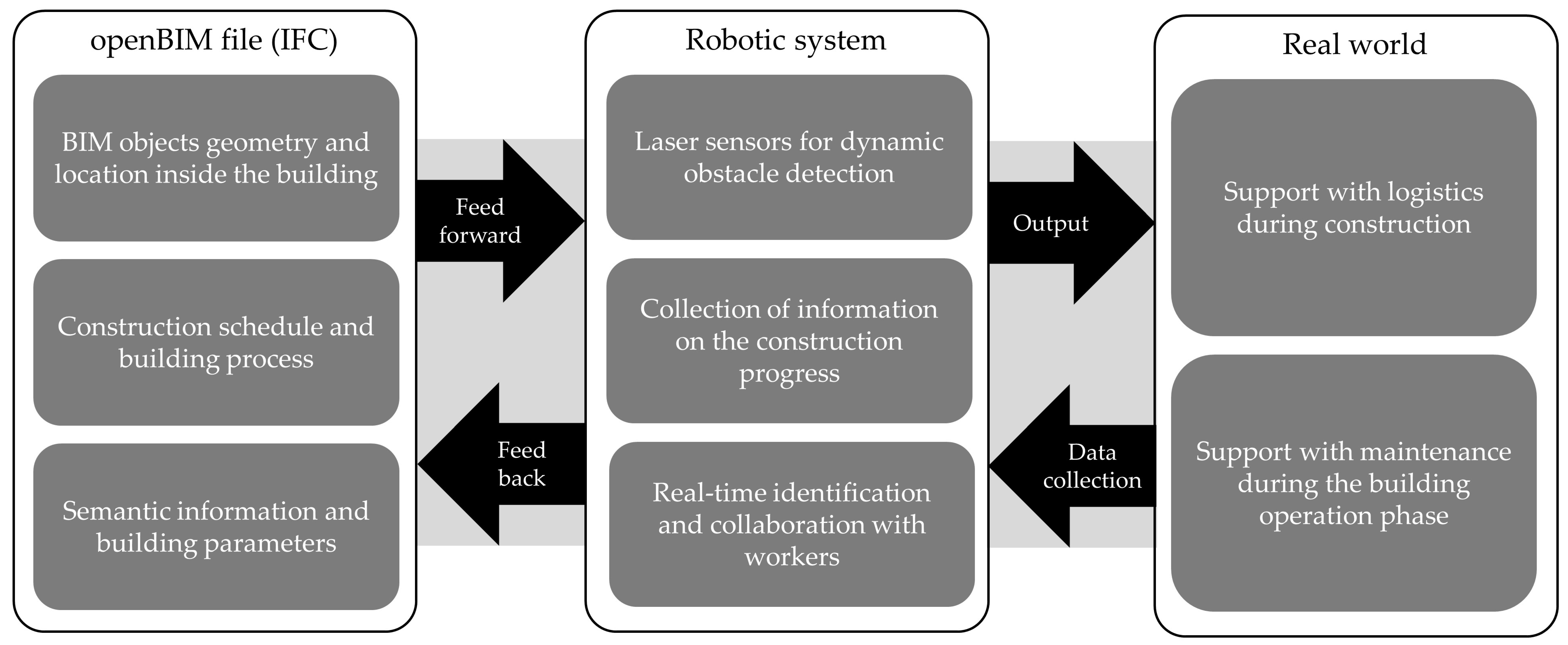
An overall summary of our applied research objectives is illustrated in
Figure 1. The BIM interface enabled a bidirectional connection between the robotic system and the building database. In particular, the system could query the database for three kinds of information stored in BIM objects: (1) their geometric description and location with respect to the BIM file origin; (2) the information on construction scheduling, phasing, and process; and (3) the other metadata stored in pre-set and custom BIM parameters that semantically define the objects and areas of the environment. This information was provided a priori to the robotic system before operation. The system’s goal, as shown on the rightmost side of the picture, was to support construction and maintenance operation. The robotic system itself was provided with sensors to align the building model with the real world. The sensors were also employed to detect unforeseen obstacles, which were expected due to the unstructured environment of the construction site. Finally, the system identified workers in order to collaborate with them during operations. The same workers could input information on the construction progress in order to update the initial parameter value in the BIM database.
Our proposed pipeline for BIM integration was based on the Industry Foundation Classes (IFC) [
25]. In fact, BIM authoring software tools have the option of exporting projects in the IFC format, making the information stored inside openly accessible. The IFC format is standardized by the ISO 16739-1:2018 [
26]. Its main purpose is to achieve and promote the “open BIM” paradigm by creating a common, structured format for exchange along the construction industry supply chain during the entire building lifecycle. Examples of software tools that can be interfaced through IFC include modeling of architectural, structural, and Mechanical Electrical Plumbing (MEP) elements, site scheduling, and facility management. For this reason, the use of this format enables a strong connection to the building industry standards.
The use of BIM makes it possible to extract useful information for a robot, such as pmg maps, 3D voxel grids, room tags, and coordinates of loading and unloading areas. With this aim, we proposed an ROS-based interface written in Python 3 that made the information stored in the IFC accessible on demand. Geometrical information was processed using the Open CASCADE library [
27], which was bridged with Python by the PythonOCC library [
28]. The metadata stored in the IFC structure was accessed through the open IFCOpenShell library [
29]. ROS was used for its high modularity and flexibility. Open CASCADE was used to perform 3D operations and process geometrical information. IFCOpenShell, on the other hand, enabled the creation of objects linked to their BIM property sets. Property sets made it possible to exchange standard and custom characteristics of building objects with robotics. Standard parameters concerned the topological definition of the building objects (e.g., doors, windows, and furniture), the location of the objects with respect to the map origin, and other basic information, such as their material. Custom parameters were created to expand the information beyond standard characteristics, and they usually concerned data that was relevant to construction and maintenance, such as scheduling, cost, and facility management.
In our research, the BIM interface was used for the creation of BIM-based time -dependent occupancy maps for robotic navigation (see
Figure 2). We implemented four-dimensional scheduling metadata linked to BIM objects (i.e., planned starting and ending construction dates), which were exploited to create different static maps of the same building floor that followed the construction progress. These dates were specified through custom parameters created in the BIM authoring software (i.e., Autodesk Revit© in this case) before exporting the project in the IFC 2 × 3 format. Our pipeline parsed the IFC and stored the information about the BIM objects it contained. Thereafter, it filtered them based on two criteria: first, whether they posed a potential threat of collision with the mobile robot, and second, whether they had been built at the date and time at which the interface inquired. The objects that were not filtered out after the geometric and scheduling analysis were then sectioned by a plane. The meshes resulting from the intersection were plotted into a pgm image file by exploiting the Qt-based 3D Viewer of Open CASCADE [
30]. In order to generate a grid map readable as an ROS costmap, that is, a binary map representing the obstacles of the environment with black pixels over a white background [
31], the camera was set at the top of the picture and rendered it in black and white. Finally, the map was integrated into the ROS navigation stack [
32]. This was achieved by uploading the map on the ROS node map_server [
33]. This node loaded the yaml file linked to the map, which contained additional information such as the map origin and scale. At the end of this process, the map was successfully delivered to the robotic system.
As shown in
Figure 1, the last objective of the BIM interface was the extraction and modification of BIM object parameters. We focused on two specific BIM objects types for the sake of providing examples of processing physical and nonphysical BIM entities.
Figure 3 shows the chain of elements, distinguished into IFC and relationship entities, that connected the building floor to a specific element and its property sets. This figure focuses on IfcSpaces [
34] as representatives of nonphysical entities and on IfcEnergyConversionDevices [
35] as representatives of physical entities. In the open BIM definition, IfcSpaces are three-dimensional volumes that define rooms that are actually or theoretically bounded. Thus, they are meant to describe the functions of building rooms, such as, for instance, meeting rooms, laboratories, and office spaces. The BIM interface extracted the geometric description of these IfcSpaces linked to their function and room code. Other parameters could concern, but were not limited to, storage spaces during the construction phase or daily room occupation status during the building operation phase. IfcEnergyConversionDevices are an example of how MEP elements were represented in BIM. MEP elements were chosen as they represent elements produced off-site that need to be installed during the construction phase and regularly maintained during the operation phase. Thus, they provide a comprehensive example of a BIM object characterized by specific information parameters that are shared among stakeholders from different fields and that are used throughout the building lifecycle. They are characterized by the parameters of their off-site producer, such as object code, serial number, and warranty information, and they are often linked with external documents on the use and installation process. During construction, they can be linked with parameters on scheduling, such as installation status and installation date. After these parameters were retrieved by the BIM interface, it was possible to identify the line in the IFC project where the parameter content was stored to potentially change its content. Upon importing the IFC into building software tools, the parameter was listed with the updated information to provide feedback from the robotic system to the construction stakeholders.
Algorithm 1 shows the detailed process for the creation of the BIM-based maps. It can be divided into three main parts. The first part of the algorithm (lines 3–20) is the parsing of the IFC file and the filtering of relevant objects, summarizing the process described in
Figure 2. Physical and nonphysical objects are distinguished through their IfcProductRepresentation [
36] flag. Geometrical filtering is dependent on the lowest z value of the bounding boxes for physical objects; that is, whether their base is located above the mobile platform (line 6). This enabled filtering of all objects that posed no risk of collision, such as, for example, the thermal panels installed on the ceiling. In contrast, geometrical filtering of nonphysical objects focuses on those located on the ground level (line 14) to identify holes on the floor slab. Time-dependent filtering is based on the retrieval of the two custom parameters through the process shown in
Figure 3 (lines 7–9). Again, a distinction is necessary between physical and nonphysical objects. If the object is physical, it is considered an obstacle after its construction starting date. This enabled the simulation of the construction of building elements, such as walls and columns. If the object is nonphysical, it is considered an obstacle only during the time between its starting and ending date. This enabled the establishment of no-go areas in the navigation maps during the time a hole in the floor slab was present. The second part of the algorithm (lines 21–25) is the creation of the section of the objects that are not filtered out. The section plane is located at the height of the robotic sensor to ease indoor localization. Through Open CASCADE it is possible to retrieve the edges at the intersection between the section plane and the BIM objects. The edges are used to create the 2D surfaces representing the section. The resulting surfaces are finally shown in the 3D viewer embedded in Open CASCADE. The third and final part of the algorithm (lines 26–29) is the plotting of the map. The viewer’s camera settings are used to create the black and white binary grid map. The view is fit to the camera window and subsequently scaled, based on the resolution ratio, given in pixel per meter, and the bounding box encompassing the building. The resolution, the map origin and the link to the map picture are written into a yaml file and transmitted to the map server.
| Algorithm1: Generation of BIM-based gridmaps. |
|---|
Input: BIM model (IFC), floor number F, resolution RInitialize 3D viewer V Import of the ifc file IFC For IfcProduct objects O in IFC in floor F Create Bounding Box B Create section plane S located at robot’s sensor z plane If lowest z value of B ≤ robot height H For Attributes linked to O Parse for attribute “Starting Date” Ds and “Ending Date” De End For If O has Representation If current date > Ds Store O in product list L End If ElseIf O has no Representation & highest z value of B is equal to ground level If Ds < current date < De Store O in product list L End If End If End If End for For objects in L Generate edges list E at the intersection with S Generate close wires list W from E Generate surfaces list Sf from W End for Visualize surfaces Sf in V in black Set Open CASCADE camera parameters (top view, white background, fit all) Compute image dimensions (pixel) through R Creation of pgm image containing the camera view
|
4. Applications Considered for Validation
The BIM interface was validated in two main applications with an increasing level of complexity. In both application scenarios, we interfaced the BIM with a Mobile Robotic Platform (MRP) to support site logistics; that is, the MRP followed an operator while carrying heavy loads, such as construction material or equipment. To achieve this, the development focused on three main parts: (1) a follow-me function, (2) dynamic obstacle detection, and (3) the extraction of data from the BIM file to ease navigation.
In the first application, the problem was simplified using the following assumptions: (1) a BIM file exists which has parameters for scheduling and for navigation; (2) the MRP knows its starting position in the given BIM map; and (3) a global tracking system is provided to locate both the MRP and the operator at any given time. The second application was aimed at relaxing these three assumptions. Due to this, only the use of sensors mounted on the MRP was permitted. This resulted in a solution that did not rely on a fixed tracking system and that was able to locate itself on the BIM map. This, however, required new assumptions, mainly: (1) the operator is constantly in the Field of View (FOV) of the MRP’s camera for the follow-me functionality; (2) the platform moves only forwards; and (3) the BIM project of the building is available and it precisely represents reality (i.e., there are no discrepancies between drawn and built elements). The second application was also employed to test the use of semantic information extracted from the BIM projects with the aim of its better integration into the construction and maintenance processes.
The first application scenario was a robotic system to support site logistics during the construction phase. The follow-me function on the MRP was developed using an indoor tracking system to make use of its accurate measurements of the position and orientation of the tracked bodies. The desired trajectory of the follow-me function was calculated by tracking the position of both the MRP and the operator. These two objects could be tracked thanks to spherical reflective markers that were fixed on the platform and on a construction helmet, respectively. The relative positions were then translated into a world coordinate system, which was defined by the tracking system. The implementation of dynamic obstacle avoidance was realized through two planar LIDAR sensors. In the first application, before the real system was tested, several simulations were performed. The setup consisted of a PC running the ROS and Gazebo [
37], an ROS-enabled software for robotic simulation. The tracking system employed was produced by the company ART [
38]. It consisted of four tracking cameras, a computing unit in the form of a rack, and several marker configurations. The MRP was a Clearpath Husky A200 [
39]. This vehicle is specifically designed for research activities in harsh outdoor environments. The user bay of the MRP was equipped with a computing unit running the ROS and a network switch. The MRP is equipped with two LIDAR sensors, respectively pointing forward and backward, each with a 270° planar FOV. In addition, the MRP was equipped with an Inertial Measurement Unit (IMU) that provided acceleration and angular velocity measurements in the Cartesian coordinate system. The control PC was a Dell Latitude E6420 running Linux Ubuntu 16.04 and ROS Kinetic. This PC was needed to launch the overall control architecture, as well as the bridge to the tracking system. The LIDAR sensors were connected over an ethernet interface to the computer of the MRP. The MRP included a local network that had a wireless connection to the external network. The external network consisted of a router that connected the computing unit of the tracking system and the ROS-led PC. Since the system included two computers running the ROS, a time synchronization of the two systems was required. This synchronization was realized over the Network Time Protocol deamon chrony [
40], running both on the MRP and the control PC. An overview of the different hardware components can be seen in the depiction of the setup shown in
Figure 4.
The overall software architecture of the system is shown in
Figure 5. Here, we distinguished between nodes that we developed and those available as open-source nodes or ROS packages. The PC on the MRP ran one of the master nodes named roscore. This node interfaced the LIDAR scanner-generated messages (/laser) and a node that controlled the MRP (husky_ctrl). A second roscore was run by the control PC. It enabled: (1) the art_bridge node, which interfaced the data coming from the tracking system to tf-messages [
41] in the ROS, (2) a controller node for the follow-me algorithm, (3) the nav2d package [
42], visualized as the Operator node in
Figure 5, that included nodes for various purposes (such as mapping managing, trajectory planning, and obstacle avoidance), and (4) a node for the map server, which fed the static map coming from the BIM-interface into the global costmap.
The art_bridge node received the data from the ART tracking system over a User Datagram Protocol interface and composed a tf message according to each coordinate frame received. This use of tf-frames within the ROS enables their visualization (e.g., in Rviz [
43]), as well as the use of related coordinate system transformation tools. The tracking system used a custom data format for each tracked coordinate frame. The follow_me_ctrl node enabled the follow-me algorithm. The inputs of this node were the art_bridge tf messages, while the output was a custom message type cmd, defined by the nav2d package. The node registered the current position of the vehicle and computed the vector to the target, which was defined by the coordinate frame of the tracked helmet. Thanks to that, the desired turn value and speed got calculated. When the MRP was close to the target, the system set its velocity to 0 to stop the MRP in near proximity to the operator.
In the second application scenario, the same MRP and user bay equipment were employed. The user bay contained a computing unit, a network switch, and an IMU, which provided acceleration and angular velocity measurements in the Cartesian coordinate system. Differently from before, only one LIDAR sensor with a 270° planar view was used. The sensor was facing forward since one of the initial assumptions was that the MRP would not move backwards. The sensor was mounted at a higher position to increase the ground clearance. Additionally, an Intel RealSense D435 [
44] was mounted on a frame to increase the amount of input data. In particular, the data received from the camera were used to identify the person the MRP was currently following and to distinguish them from other people present in the MRP’s workspace. The data obtained by the camera were processed by an Nvidia Jetson Xavier AGX Developer Kit [
45], since the internal computing unit was not suitable for computer vision tasks. The Jetson Xavier AGX was also placed in the user bay. The two computing units and the LIDAR were connected through the network switch, so that they worked in one local network. The RealSense was instead connected to the Jetson Xavier AGX through a USB Type C cable. The internal computing unit of the MRP was additionally connected via wireless, which allowed monitoring of the system from another PC in the same network. Similarly to the previous setup, all computers had to be time-synchronized to allow reliable time-stamped communication. An overview of the full hardware setup for the second application is shown in
Figure 6.
This new configuration prompted a modification of both the follow-me control and the integration of the BIM-generated map. The follow-me function had to be modified to comply with the new uncertainty of tracking a person in an unknown environment. A new software architecture was proposed, which was based on the three subcategories presented in [
46]: perception, estimation, and control. The architecture focused on the estimation of a target’s position. Perception described the incoming data from the different sources. Estimation concerned the analysis and interpretation of this input data. Finally, control established how the MRP reacted to given circumstances. One major focus was to keep the architecture modular since packages for person tracking can become outdated in a short time. This meant that all the algorithms used for specific tasks could be exchanged independently, without having to modify the overall system.
The perception module made use of incoming data from both the LIDAR and the RealSense camera. Its goal was to obtain information on people, in particular on the target to follow. This was achieved using a leg detector that parsed the 2D laser data to identify people and obtain their 3D pose. Additionally, YOLO v3 object detection [
47] was used to obtain both poses and pictures of people by tacking the bounding boxes that YOLO generates. The target position estimation itself was divided into different submodules: person tracking, feature extraction, and re-identification. The person tracking module estimated the next target position by using the information from older measurements. The feature extraction module described each person with a descriptive array. This descriptive array was then used by the re-identification module to learn the features of the target person online, so that it could distinguish them from other people when the person tracking module could not exactly establish who the target was. Finally, the control module did not substantially change from the follow-me function developed in the first setup.
5. Application Results
In the first application, the BIM integration was used to increase the robustness of robotic navigation. In particular, the BIM-generated time-dependent obstacle map was superimposed onto the map based on the LIDAR sensors from the MRP in order to avoid specific areas in certain time frames. The creation of the map followed the procedure shown in
Figure 2. We conducted experiments on the first application in a laboratory environment to test the effectiveness of the proposed method. A simple IFC file was used that contained only the lab boundaries (i.e., walls and access door) and an element in the center of the room representing an unsafe area on the ground. The section plane was placed at the same height of the LIDAR sensor. The no-go area could, for instance, highlight where undetectable elements had been posed on the ground and which should not be moved by the MRP (e.g., electrical cables, measuring tapes). We considered other small obstacles that can be commonly found on construction sites, such as debris or unlevelled floor parts, to be negligible since we expected that the MRP would be able to drive over them, as the LIDAR was positioned under the plane passing through the center of the wheels. As shown in
Figure 7, there was no distinction between the BIM-generated virtual obstacles and the ones dynamically detected by the LIDARs. Therefore, the MRP adjusted its trajectory to avoid both.
The second application was tested in a simulation. The generation of the BIM-based map followed the process of the previous setup shown in
Figure 2. The BIM model used contained the entire floor on which the laboratory with the initial fixed tracking system was located. Two time-dependent IfcWall objects enclosed a specific area in which the MRP was not supposed to navigate. This could simulate either the construction of new walls on-site or the establishment of a no-go area. Differently from the first experiment, in this application the BIM grid map was used by the AMCL algorithm to automatically align with the BIM reference system. Another difference with respect to the first application was the integration of semantic data that were extracted from the BIM model through the process shown in
Figure 3. In order to quantify the benefit of the proposed approach, we developed a simulation to access and compare the time that the robot needed to reach a target location using the grid map extracted from the BIM with the time needed when a classic static map of the environment was available. To fully exploit the BIM data, the following scenario was examined. The MRP was again employed to assist with logistics during maintenance of thermal panels located on the building floor ceiling. The building rooms were semantically identified thanks to the BIM interface. The MRP was called to a room where required equipment and material was located by the operator and then loaded. Thereafter, it started following the operator to the intended maintenance point. After the work was completed, the parameter of the IFC file was updated.
As shown in
Figure 8, the MRP was requested to navigate to the laboratory room starting from a random valid pose. This was tested using the two maps described above. In the first experiment (
Figure 8a), the MRP reached the laboratory room following the shortest path. The path did not consider the temporary obstacles in the environment since the robot did not have any connection with the BIM model. In the second experiment (
Figure 8b), the MRP planned a different path since the original was blocked by the time-dependent virtual obstacle. The BIM-generated map made it possible to plan the route ahead. Without it, the MRP attempted the shortest path and was then blocked by the temporary obstacle. As soon as it reached the obstacle, the system replanned the route to reach the lab, passing through the obstacle-free eastern corridor. Thanks to the BIM map, the system was thus able to plan the shortest obstacle-aware path for that time frame.
Figure 9 shows a comparison of the followed path in two scenarios. The dashed line indicates the path followed when the temporary obstacle was not known a priori. In this case, the MRP had to reach the temporary obstacle location before understanding that the way was blocked. From there, it replanned its route. The continuous line represents the path followed considering the presence of the temporary obstacle, as enabled by integration with the BIM model. This represents an example in which the BIM integration strongly aided navigation.
The experiment described was performed 4500 times for each map—for a total of 9000 times—in simulation. For every execution, a random starting pose of the robot was automatically initialized. As the goal pose the robot was asked to reach the laboratory at the top right corner.
Figure 10 shows the distribution of the measured execution times (including the planning and path following phases). The distribution clearly shows a higher performance overall of the system with the a priori knowledge of BIM. The BIM-integrated navigation execution times were between 50 and 125 s, depending on the path length. Without provision of the BIM-based map, the same routes were completed with execution times between 50 and 150 s due to the lack of prior knowledge about the temporary obstacle. Thus, thanks to the BIM integration, the system generally performed the same task in less time.
Figure 11 presents the time differences for the execution times of the navigation task from the same starting location. In some of the experiments, the execution time was only slightly inferior or even better without the use of the BIM map. This happened when the random path did not intersect the temporary obstacle. In these cases, the BIM knowledge did not improve the navigation time. In contrast, when the path passed through the area where maintenance works were taking place, the BIM integration could save between 20 and 60 s of execution time. The distribution in
Figure 11 is trimodal and it presents three distinct peaks:
The first peak—the interval from −10 to +10 s—represents the cases in which the path was not blocked by the maintenance works. In these cases, the position of the starting pose intrinsically pushed the planner to plan a path that did not pass close to the temporary obstacles and, therefore, the BIM integration did not improve the navigation time.
The second peak—between +10 and +30 s—represents cases in which the starting point was located on the upper side of the map. In these cases, the MRP could clearly see during motion that there was an incoming obstacle blocking its path. Thanks to this, the system was able to replan the navigation path more quickly. Moreover, due to the typical Manhattan shape of the building room disposition, the length difference between the two paths at the end of the navigation was minimal. In these cases, there was a relevant time difference between the two compared scenarios.
The third peak—between 30 and 60 s—represents cases in which the BIM integration was critical for path execution. This peak includes the example shown in
Figure 9. Here, the starting point was located in the lower side of the map. The MRP needed to travel a significant part of the planned path to sense the obstacle and was then forced to reverse its course. In contrast, the a priori knowledge of the maintenance works made it possible to plan an obstacle-free path at the beginning of the execution. This resulted in a major difference between the two execution times. Specifically, the percentage of improvement reached up to 53%, with a mean value of 20%, in this scenario.
6. Discussion
The interface was validated on two applications with an increasing level of complexity. In the first application, a BIM-based grid map was used to mark no-go areas for the navigation of an MRP. Here, a fixed tracking system was used to identify the position of the user and the robot. In the second application, the person tracking required only the sensors mounted on the MRP, relaxing the need for a fixed system. This was pursued to adapt the system to the requirements of construction sites.
With regard to the operation phase, the method is also for use with more detailed data based on the real-time information about a building. This is possible through the integration of 6D BIM data, specifically the dimension connected to Facility Management (FM) arriving from FM tools or sensors, which is a current theme in BIM-related research [
48]. If, for example, a BIM database with real time information on room occupancy existed, navigation could be further improved to avoid certain rooms or open spaces occupied within a certain timeframe. This would be achievable by parsing the IFC file for IfcSpaces and reading a parameter on time, date, and status of room occupancy. If the room were declared occupied in the IFC at the time of use, the map delivered to the robot would render the room inaccessible. As mentioned previously, another implementation performed was a simple bidirectional information exchange in the context of updating the status of construction and maintaining operations. This made it possible to acquire a BIM database in which information on operations was constantly updated in the IFC file during building construction and maintenance phases. This was achieved with a simple exchange through a specific parameter linked to the BIM object representing the thermal panel discussed in
Section 3. Specifically, we used the BIM interface to identify the line in the IFC structure where the property sets of a specific panel were stored through the process shown
Figure 3. As shown in
Figure 12, we added parameters to the IFC file to simulate information on the panel installation status and date of installation. The lines in which these parameters were stored could be retrieved through the BIM interface. This made it possible to rewrite the content of these parameters with updated input that was supposedly linked to the real-world installation progress. This simulated a return of information from the site to the BIM’s specific object. Although this implementation is still in an early stage, it can enable any software tool capable of importing IFCs to acquire updated information on construction operations. Therefore, it can generally ease the interface between the robotic systems and the construction supply chain, which is one of the main barriers for application of construction robots [
8].
7. Conclusions
The paper presents the development of an interface to extract data from a BIM model and make it accessible to mobile robotic systems. Thanks to the modularity of ROS, it is possible to easily adapt the work presented in this paper for the control of systems with different configurations. As BIM is steadily becoming a standard in the construction supply chain, an interface with the BIM model will play a major role in the future employment of robotic systems in the construction industry.
A future development goal of our research is to exploit the data registered by the MRP to automatically update the construction progress in the IFC with the method used above. There has been great interest in BIM-enabled autonomous mobile scanning systems in the construction field in recent years. Developments range from research projects [
49,
50,
51] to startups launched on the market [
52,
53,
54,
55]. These usually involve using algorithms for object recognition and Scan-vs-BIM or Scan-to-BIM methods [
49]. Our proposed interface may be used to enable the collection of the data needed for monitoring while concretely supporting the construction progress.
Moreover, as an extension of this research, our results can remarkably facilitate the deployment of robotic systems for service operations in buildings. Robotic service systems are highly desirable in the current COVID-19 pandemic to reduce human exposure to risks. Among other duties, suitably designed robots can be employed for disinfection tasks. Several robotic solutions for disinfection have been recently developed, for instance, based on ultraviolet light [
56,
57,
58,
59,
60], spraying of disinfectant [
60,
61], or a combination of both [
60]. The navigation of the existing robotic systems is enabled using ROS and sensor data [
57,
58,
61], embedded navigation and localization with deep learning for semantic environment mapping [
56], and the use of predefined maps of areas to disinfect [
60]. Our results enable us to enhance perception and navigation capabilities of robotic systems thanks to the bidirectional connection to IFC files, where metadata is updated to be readable on authoring BIM software tools. With respect to other existing approaches considering disinfection operations, such integration can facilitate the detection of crucial areas and critical components that need treatment within large facilities. Use of prior knowledge of the buildings from BIM for robot control is promising for the reduction of time-consuming programming of robot motion plans or the need to perform seek-and-identify missions. This outlook summarizes the fundamental idea of our currently active project named BALTO. The project builds on our proposed BIM-integrated robotics approaches towards realizing simple-to-deploy robotic systems for precise disinfection operations in buildings.
Finally, future work will also address the evaluation of the actual applicability of the system in an outdoor construction site. This environment is characterized by many more challenges for robotic systems. Among these, the most relevant are the unstructured space subject to weather conditions, the very rough tolerance of operation (, and the collaboration with workers not used to robotic systems [
62]. We believe future advances in our interface will be helpful in overcoming these issues and contributing to bridging the gap between robotic systems and construction sites.


 ,
, 


