Article

Unified System Network Architecture: Flexible and Area-Efficient NoC Architecture with Multiple Ports and Cores

1
Department of Information and Telecommunications Engineering, Soongsil University, Seoul 06978, Korea
2
School of Electronic Engineering, Soongsil University, Seoul 06978, Korea
*
Author to whom correspondence should be addressed.
Electronics 2020, 9(8), 1316; https://doi.org/10.3390/electronics9081316
Submission received: 28 July 2020 / Revised: 9 August 2020 / Accepted: 13 August 2020 / Published: 15 August 2020

Abstract

:
In recent years, as semiconductor manufacturing processes have been steadily scaled down, the transistor count fabricated on a single silicon die can reach up to a billion units. Therefore, current multiprocessor system-on-chips (MPSoCs) can include up to hundreds or even thousands of cores and additional accelerators for high-performance systems. Network-on-chips (NoCs) have become an attractive solution for interconnects, which are critical components of MPSoCs in terms of system performance. In this study, a highly flexible and area-efficient NoC architecture, namely the unified system network architecture (USNA), which can be tailored for various topologies, is proposed. The USNA provides high flexibility in port placements with varying numbers of local cores and router linkers. It also supports quality of service operations for both the router and linker. The network performance (e.g., average latency and saturated throughput) and implementation cost of the USNA, using various network configurations for the same number of local cores under uniform random traffic conditions, were investigated in this study. According to the simulation results, the performance of the USNA is better or similar to other NoCs, with a significantly smaller area and lower power consumption.

1. Introduction

The number of processing cores integrated into multiprocessor system-on-chips (MPSoCs) has increased rapidly, and conventional shared or multiple channel on-chip buses are no longer suitable as interconnect modules. Consequently, network-on-chips (NoCs) have become a crucial component for the overall system performance to provide parallelism and scalability. The design of NoCs typically requires the satisfaction of multiple conflicting constraints, including minimizing packet latency, reducing the router area, and lowering communication energy overheads [1]. MPSoC systems are employed in many applications, such as networking, signal processing, general purpose, and deep neural networks, to meet the growing functional demands. The NoC, therefore, must be sufficiently flexible to support a wide range of on-chip communication scenarios and quality-of-service (QoS) requirements.
Conventional NoCs consist of five-port routers, to which only one local core can be attached per router [2,3,
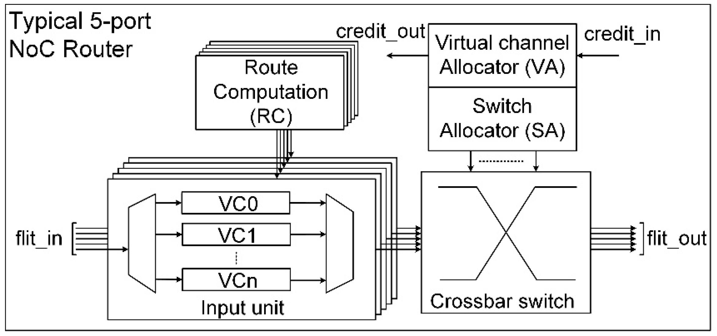
4]. A flit passes through a router to the next hop after five stages of the routing process: route computation (RC), virtual channel allocator (VA), switch allocator (SA), switch traversal (ST), and link traversal (LT). Each input port of the router is equipped with collections of buffers referred to as virtual channels (VCs), which make the router complex. Although the VCs can improve the saturated bandwidth of the network, they do not increase the actual router bandwidth; rather than increasing the physical channels of the router, they incur a larger area overhead [5]. Therefore, many multiport NoCs have employed 7-, 9-, 10-, or 11-port routers, which increase the physical channels of the router, and therefore, increase the maximum number of flits concurrently delivered through a router [5,6,7].
There are two types of transactions that support the QoS in NoCs—guaranteed throughput (GT) and best effort (BE) traffic; further, GT is often given higher priority than BE [8]. The network must meet the throughput and latency requirements of the GT traffic communications over a finite time interval between sources and destinations, while it attempts to forward packets of the BE traffic to destinations whenever possible, without satisfying any constraints. The two basic approaches in NoC designs to make the QoS support possible are reserved connections (hard guarantee) and prioritized routings (soft guarantee) [9]. The soft guarantee, which is based on packet switching with multiple VCs, is usually employed. The hard guarantee, where the GT packets are never blocked by the BE packets, is obtained by circuit switching, where routing resources of an entire routing path from the source to destination need to be reserved. Most NoCs provide the BE service based on wormhole packet switching because of its efficient bandwidth utilization and high throughput [2,3,4].
Wang and Bagherzadeh [7] proposed a QoS-aware and congestion-aware multiport router architecture that exploits adaptive routing and multiple parallel buffers to provide the QoS for differentiated service classes with reasonable implementation costs compared with those of conventional NoCs. Their experimental results demonstrated that sharing routing resources (e.g., parallel buffers), as the network load increases for both BE and GT traffic, achieves better performance in latency and resource utilization than the reserved resource approach. Carara et al. [5] proposed a 10-port NoC that duplicates the physical channels of the conventional router and provides various QoSs. However, the QoS may be affected when there are conflicts among high-priority traffic flows for the same routing paths, incurring high implementation costs because of the complex QoS control mechanism and the doubled number of ports. Ruaro et al. [10] proposed a duplicated channel NoC that tracks the communication performance at runtime to dynamically change between the circuit and packet switching techniques according to the application requirements. Although this reduces the number of deadline violations for soft guaranteed services, it does not completely address this issue and QoS control is still complex. Dorai et al. [11] proposed an NoC with double physical planes to support multimedia applications by controlling the traffic injection of four service levels. All the above mentioned NoCs were designed with fixed topologies and complicated router structures, which not only are difficult to apply in diverse traffic patterns but also consume a large chip area.
Because NoCs often consume a large portion (up to 40%) of the total chip power [12], power efficiency is also an important aspect that needs to be carefully considered. Existing studies have stated that buffers are the most dominant factors, contributing at least 50%, for both the area and power in the conventional 5-port NoC (NoC5) [13,14]. This percentage increases significantly in multiport NoCs. Therefore, it is necessary to reduce the buffer amount as much as possible without significantly degrading the performance.
In this study, we propose a flexible and simplified NoC architecture, referred to as the unified system network architecture (USNA), which consists of routers and linkers that are used to configure various network topologies with various traffic patterns depending on the application. The architecture can also provide an acceptable soft guarantee at a very low cost. The router has multiple ports on which processor cores or linkers can be attached; the linker, which determines the operation types of the network, connects two adjacent routers, and can be register-sliced, a set of VCs, or a combination of both. The USNA provides flexibility for network configurations, so that system designers can easily customize the network in accordance with applications during the designing process. Additionally, a communication channel with zero latency can be established between the adjacent ports without the arbitration of a router. By allowing more than one local core per router, the network size can be reduced, which reduces the average routing distance, or the network size can be extended for the same number of local cores, where some routers can be configured as fully connecting components for communication-centric applications. Various USNA configurations have been simulated and analyzed to observe their effects on network performance under uniform random traffic and implementation costs. Additionally, the performance of the USNA is compared with that of other NoCs.

2. Related Works

2.1. Conventional NoC Architecture

The conventional NoC5 typically employs wormhole packet switching with VC flow control, including five functional blocks in the router design: input units, RC, VA, SA, and a crossbar switch, as shown in Figure 1. Only the head flit of a packet needs to move through all stages, while the body and tail flits can skip the RC and VA stages. They simply inherit the routing resources allocated to the head flit to complete the transmission of the entire packet. Two types of conflict occur when the flits move through the router. The first one occurs when the flits stored in the VCs of an input port attempt to gain access simultaneously to the shared internal output channel of the VC (or the input of the crossbar switch). The second one occurs when the flits compete for the same output port at the SA stage. These conflicts require a very complicated logic circuit, which may increase the hardware cost. Another limitation of the conventional NoCs is the lack of network flexibility. Once a router is designed, the function of each port is fixed, which limits the topology of the network.

2.2. Multiport NoC Architecture

2.2.1. 7-Port NePA NoC

The networked processor array (NePA) is an enhanced version of the conventional NoC5 [6]. It has 7-port routers with two additional vertical links in the south and north directions for enhanced bandwidth. The NePA router includes two disjoint sub-routers with dedicated vertical links and shared horizontal links. After a packet is injected into the router, it is delivered through one of the sub-routers. Consequently, the NePA prevents the cyclic acquisition of routing resources, which is the main reason for the deadlock. Moreover, NePA includes an adaptive XY-routing algorithm that determines the output port to be routed. Nevertheless, the network performance of the NePA is not significantly improved compared with that of the conventional NoC5.

2.2.2. 11-Port DMesh NoC

The diagonally linked mesh (DMesh) is an improved NoC from NePA and has routers with four additional diagonal links to reduce the average routing distance [7]. The routing algorithm of the DMesh is modified to take advantage of the diagonal links from the minimal XY-routing. The quasi-minimal routing of the DMesh selects the diagonal links over the horizontal and vertical links. Additionally, the router assigns the lowest priority to the injection port to prevent the network from overloading. Because of the added features, the DMesh performs much better than the NePA and NoC5. Both the NePA and DMesh inherit the lack of flexibility of port functions from the NoC5 and occupy large areas due to the large number of input units.

3. USNA Architecture

The USNA consists of routers and linkers. The number of ports per router can be flexibly configured, and either a local core or a linker can be attached to each port in a plug-and-play manner. The linker is used to connect the routers, and the local core is a computing unit. The number of local cores and link channels (linker) per router can be adjusted independently, depending on the application, whereas the conventional NoC can attach only one local core to the designated port. The USNA network, therefore, can be constructed in regular or customized topologies according to various application requirements. The topology defines possible routing paths through which a packet can be routed to reach its destination, which significantly affects the network performance and implementation costs. For example, one router can be eliminated without any performance degradation if the other router has two local cores, and a high communication bandwidth is not required. The behaviors at the interfaces between the router and local core and between the router and linker are similar, indicating that the local cores and linkers can be attached to any of the ports of the router. 
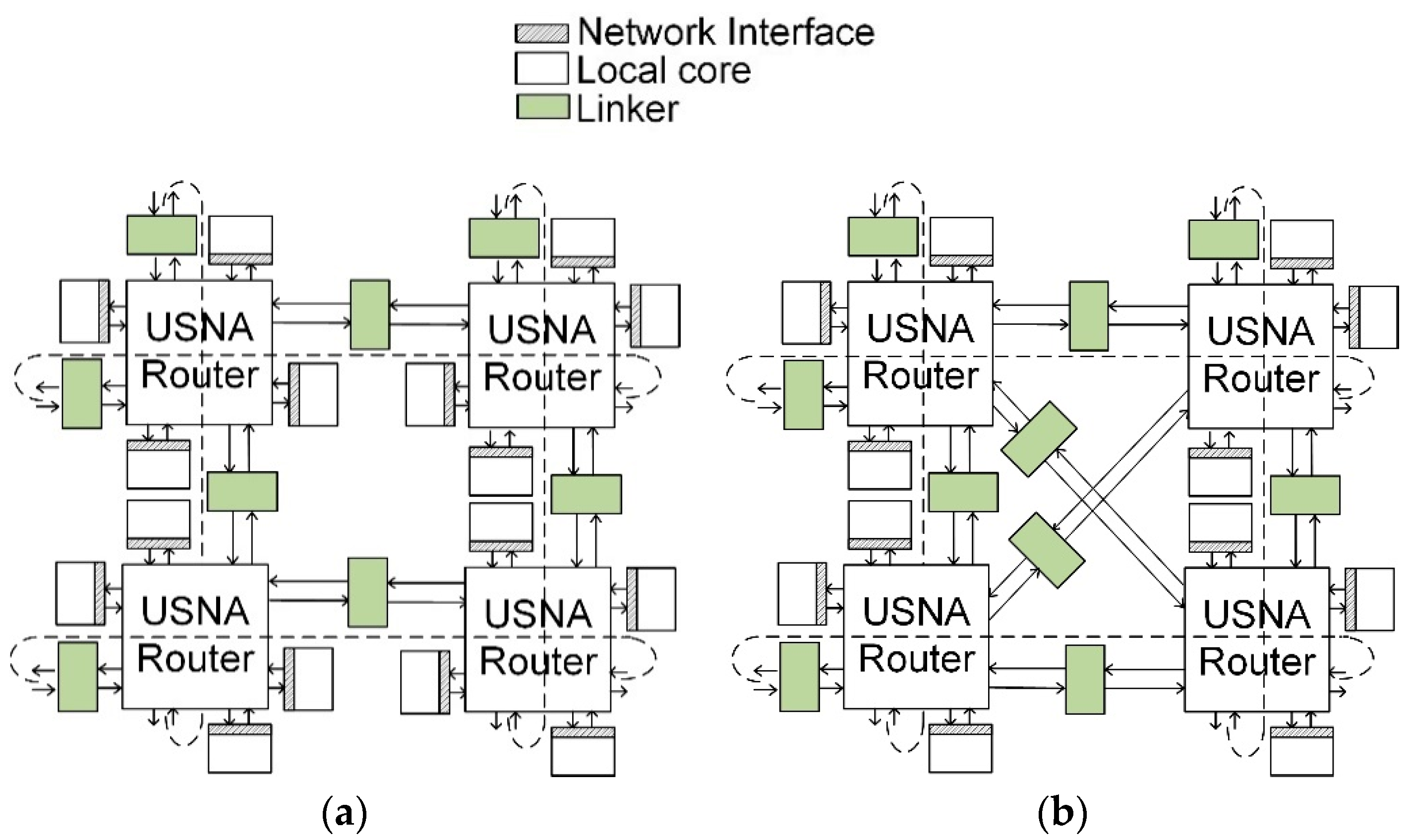
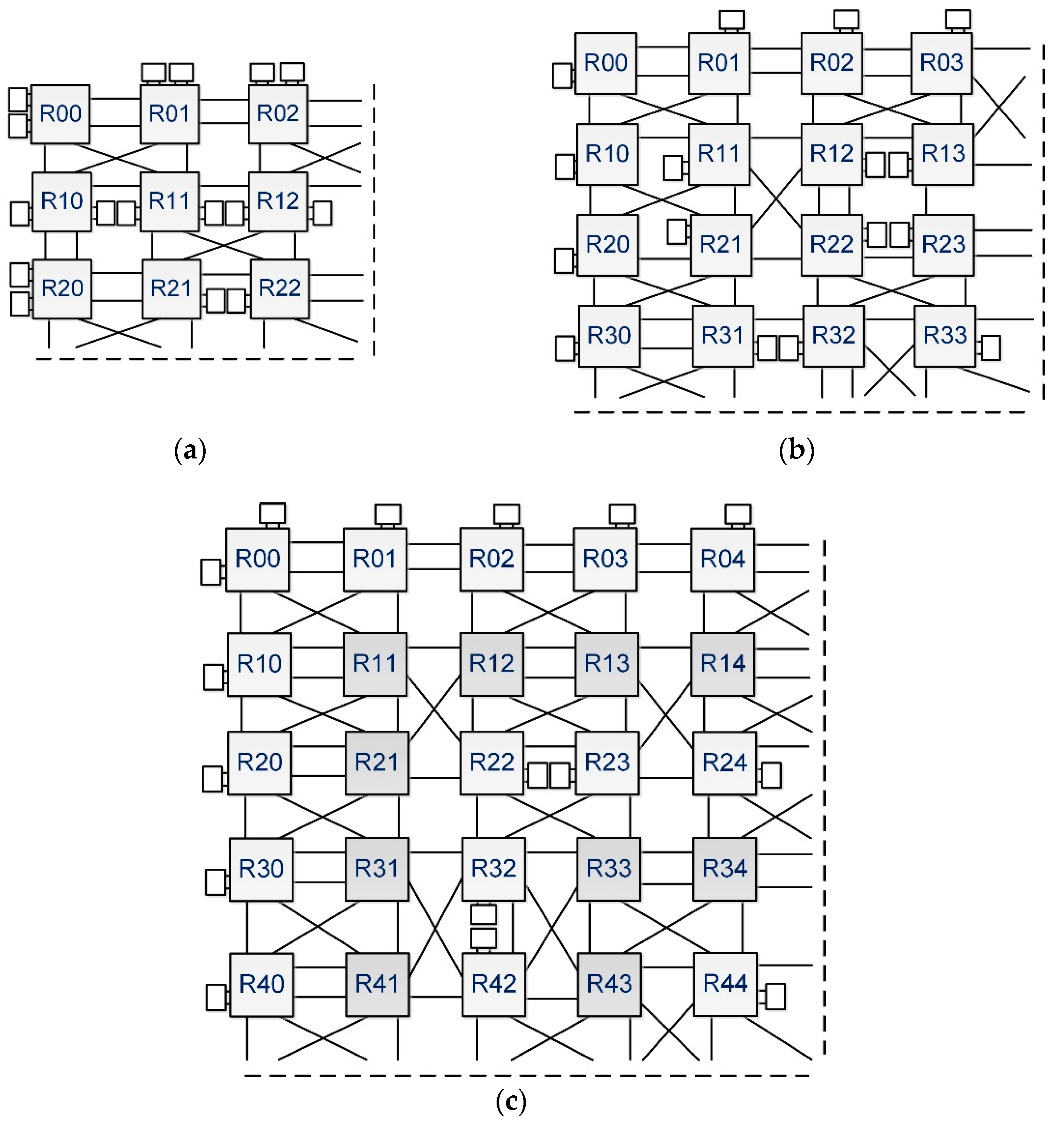
Figure 2 shows examples of 2 × 2 torus USNA network configurations with 16 and 12 local cores. Each router in Figure 2a has four local cores and linkers, respectively, and the system has four routers. If a higher communication bandwidth is desired, two linkers can replace four local cores, and can be positioned as horizontal, vertical, or diagonal links, depending on the traffic patterns, as shown in Figure 2b, where the linkers are placed in diagonal links.

3.1. Router Architecture

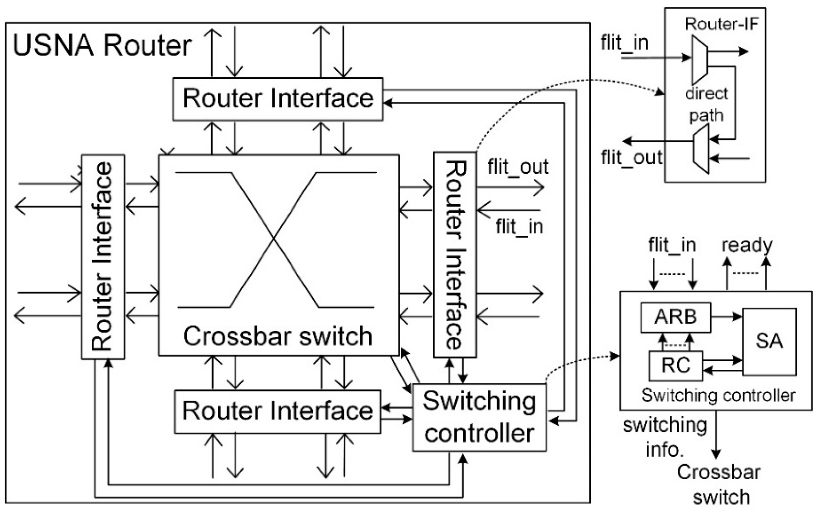
The 8-port USNA router is composed of router interfaces (router-IF), a switching controller, and a crossbar switch, as shown in Figure 3. The port of the router can hold either a local core or a linker, and the neighboring ports, which are connected to the same routing interface, can be routed directly without the switching controller. When a new packet arrives at the router (indicated by a head flit), the router interface checks if it requires “direct routing”; this is extended from the “direct routing” process used in a system network architecture (SNA) [15]. It is established inside the router interface between two ports without disturbing the switch controller. In other words, the packet can be delivered to another port through the direct path so that the router controller can handle the remaining packets. The direct routing is made in the same cycle as that when the packet arrives. If the router interface holds two linkers that do not connect the same pair of routers and the direct routing is made, the packet bypasses the router and arrives at the next router in a single cycle, which results in simultaneously transferring the packet by two hops.
If direct routing is not established, the router interface sends a routing request signal to the switching controller for “local routing”. The switching controller consists of an arbiter (ARB), an RC, and SA. The ARB chooses the highest priority head flit among the incoming ones to service every cycle in a round-robin manner. Rather than implementing an output ARB for each output port as in the conventional NoC, only one input ARB is employed at the arbitration stage for hardware simplicity. The lower priority packets may need to wait one or a few more cycles for servicing, even in the absence of conflicts of using routing resources among them. However, this does not significantly affect the network performance because the probability of concurrent multiple head flit arrivals is quite low, especially for long packet traffics. The RC then selects the available output ports after checking the statuses of the output ports issued by the SA. The arbitration stage selects the packets with the higher priorities among the packets whose output ports are available, thus, reducing the number of idle cycles in the routing process. The SA collects the information of the winner at the arbitration stage and schedules the channel formation of the crossbar switch at the next cycle. Additionally, the SA also monitors the end of the packet (the tail flit) to properly issue the statuses of the output ports to the RC. To solve the conflict at the router interface caused by the local and direct routing, higher priority is assigned to the local routing because the channel allocated to it becomes idle until the router interface releases the direct routing. However, the direct routing for the GT traffic has higher priority than the local routing for the BE traffic. A simple switching controller is implemented in this study to form one channel in a cycle and gives higher priority to the GT packets to support the QoS. This substantially reduces the implementation cost; however, it may slightly increase communication latencies when the injection rate is very high. The complexity of the crossbar switch is reduced due to the direct routing. For example, the crossbar switch of an 8-port router has the complexity of a 7-port router.

3.2. Linker

A linker connects routers and determines the packet transfer type. It can be configured as a single register slicer or piled VCs, depending on its application. 
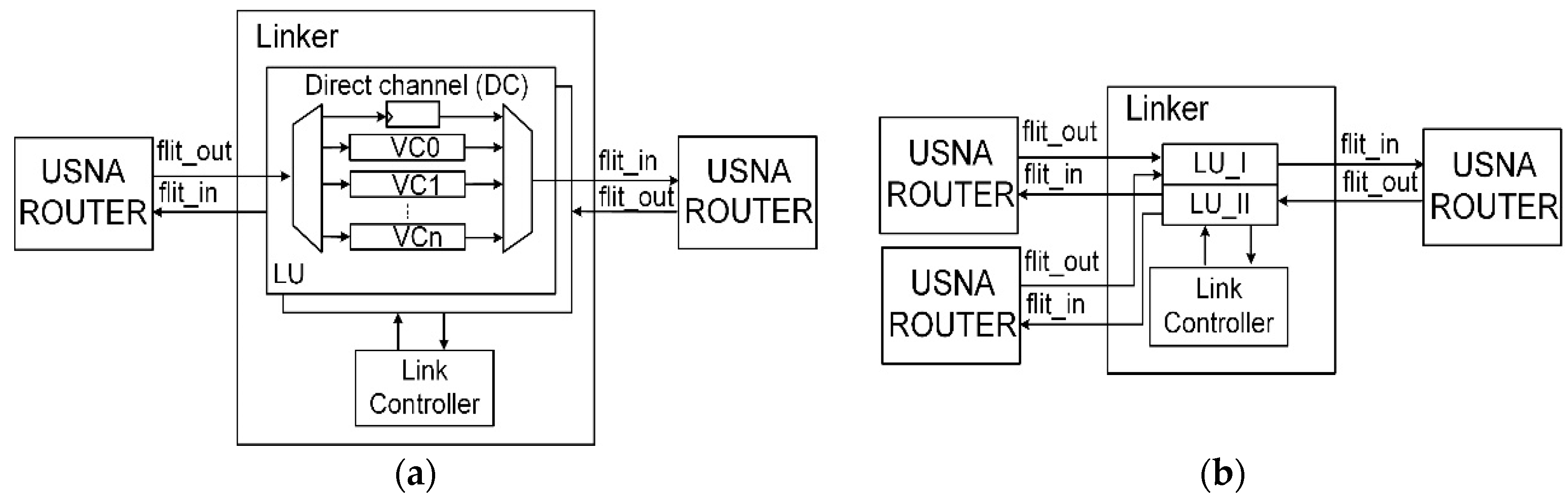
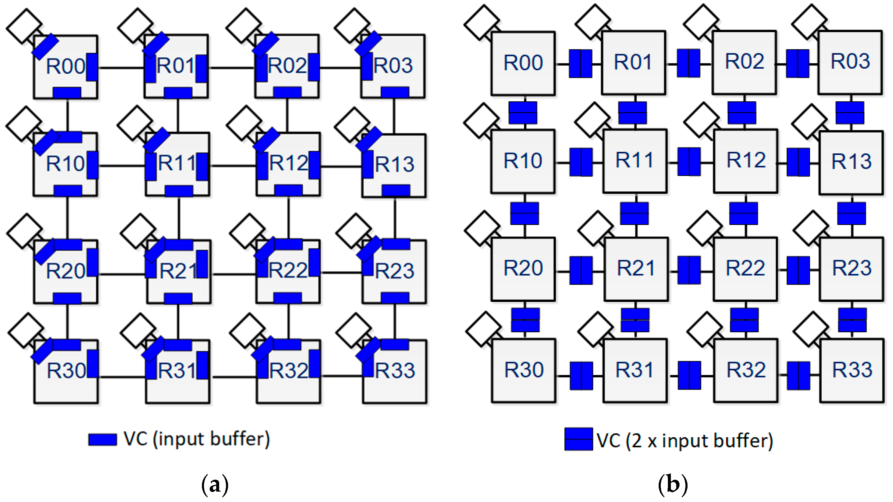
Figure 4a shows a linker with multiple VCs, and a single direct channel, which is a single register slicer used for the GT traffic. The area overhead dominated by the VC buffers is reduced in the USNA, as the injection port buffers are removed. The buffers located inside the linkers play a similar role to the input buffers in the conventional router. By moving these buffers to the linkers, we aim to modularize the design of the USNA for ease of configuration. Additionally, one row and one column of linkers can be removed from the mesh topologies, which further reduces the area overhead caused by the VCs. For example, a 4 × 4 mesh topology with the conventional NoC includes at least 64 (=3 × 4 + 4 × 8 + 5 × 4) sets of VCs, whereas that with the 5-port USNA router includes 24 (=2 × 3 × 4) sets of VCs, as shown in Figure 5. The injection ports have higher priorities than the linker ports, such that the packets are not blocked at the source’s queue. The packets then wait in the linkers for the next hop’s routing.
The routers receive and send packets simultaneously through the linkers, which include two linking units (LUs) for both directions and a link controller, as shown in Figure 4. Although the linker normally connects two routers, it may connect three routers when it has three ports, as illustrated in Figure 4b. Because the router in the USNA can have multiple local cores, it can have an orphan port that is not paired with a port of another router. A three-port linker can accommodate the orphan port. It has two types of linking units: LU-I with two inbound channels and one outbound channel, and LU-II with one inbound channel and two outbound channels. The LU-I receives packets from two routers and sends them to a router, and the LU-II receives packets from a router and sends them to the router that gives the first grant signal. Two-port linkers are considered in this study. The linker is a unique feature of the USNA compared with the conventional NoCs.

3.3. Routing Rules for Deadlock Avoidance

We propose an adaptive turn restriction routing algorithm by modifying the West-first routing [16] to exploit the advantages of the diagonal links and guarantee deadlock avoidance. The West-first algorithm is based on networks with horizontal and vertical links, and prevents creating cycling routing paths formed by 90-degree turns to avoid deadlocks. The proposed “modified West-first” routing algorithm prevents creating cycling routing paths including diagonal links because the USNA allows diagonal links. It consists of two rules: rule 1 is inherited from the West-first algorithm and rule 2 is added to the proposed algorithm as shown below. The turns that cause cyclic acquisition are prohibited according to the following rules:
  • Rule 1: 90-degree turns are restricted to West-first.
  • Rule 2: If a routing pair (source, destination) is located at the same row or column, forwarding a packet through the corresponding diagonal link is prohibited. For example, if a router forwarded a packet to a neighboring router on the right located on the same row, the possible routing paths would be the East, South, or North links; alternatively, the South–East and North–East links would be prohibited for routing in such a case.
The pseudo-code of the modified West-first routing algorithm is shown in Algorithm 1. The port list in the brackets represents the checking order to determine the final output port after taking into account the port status from left to right. For example, at the second If branch, the possible output ports can be the East (E), North (N), or South (S) port if the packet targets a destination core located in the East region. The East output port is checked first and is available for use if its port status is not busy. Otherwise, the North output port is the next candidate and the final one is the South output port. Diagonal links shorten the routing distance if communications are made between a pair of routers located at both a different column and different row. Specifically, the diagonal link is always prioritized for routing over the horizontal and vertical linkers if a packet targets the northwest, southwest, northeast, and southeast regions.
Algorithm 1 Pseudo-code of the modified West-first routing algorithm. Modified West-First Routing Algorithm
1. Input: cur_X, des_X, cur_Y, des_Y // coordinates of current and destination routers
2. Input: port_busy // statuses of output ports
3. Output: des_port // desired output port
3. Begin
5.    Xoffset = des_X − ur_X
6.    Yoffset = des_Y − cur_Y
7. If (Xoffset = 0) And (Yoffset = 0) Then des_port = {local} //local port
8. ElseIf (Xoffset > 0) And (Yoffset = 0) Then des_port = {E, N, S} //east region
9. ElseIf (Xoffset < 0) And (Yoffset = 0) Then des_port = {W} //west region
10. ElseIf (Xoffset = 0) And (Yoffset > 0) Then des_port = {S, W, E} //south region
11. ElseIf (Xoffset = 0) And (Yoffset < 0) Then des_port = {N, W, E} //north region
12. ElseIf (Xoffset < 0) And (Yoffset < 0) Then des_port = {NW-diagonal, W} // northwest region
13. ElseIf (Xoffset < 0) And (Yoffset > 0) Then des_port = {SW-diagonal, W} // southwest region
14. ElseIf (Xoffset > 0) And (Yoffset < 0) Then des_port = {NE-diagonal, E, N} // northeast region
15. Else des_port = {SE-diagonal, E, S} // southeast region
16. End

3.4. GT/BE Traffic Support in USNA

The USNA provides the soft guarantee by supporting the GT/BE traffic in the routers and linkers. The router interface analyzes the head flit to extract the QoS information and generate the routing request signal. The QoS information represents up to 16 priority levels, including the normal (or BE) packet, and the number of levels can be modified during implementation. Systems with the two-level QoS support (GT/BE) are considered in this study because most conventional NoCs support GT and BE traffic. At the arbitration stage, the switching controller gives higher priority to the packet with a higher QoS level.
The linker supports the QoS traffic when it has VCs. The structure of the linkers depends on the application operations. Each VC can be assigned to a GT packet only or shared by both the GT and BE packet. A dedicated VC is occupied by GT packets only and is idle when there are none. A shared VC can be occupied by either GT or BE packets. Networks with dedicated VCs provide higher performance for the GT traffic but incur a higher implementation cost because more VCs are usually included. The linker may include a direct channel with a single register for the GT packet, as shown in Figure 4a. The channel is reserved for the GT packet, and the linker processes the packet in the direct channel with the highest priority. The direct channel, which further increases the performance for the GT traffic when the VCs are full, can be implemented at a very low cost.
Additionally, the linker provides preemptive mechanisms that further improve the network performance. When a GT packet arrives at a linker, the linker takes the channel request token from the BE packet and initiates the channel request for the GT packet, unless a BE packet in the shared VCs has already obtained a grant at the next hop’s arbitration. The GT packet may be blocked by a BE packet that has already occupied the physical channel. If another GT packet occupies the VC and it does not obtain a grant signal, the linker alternatively gives the request token to the GT packets in the VCs to prevent a long waiting time. On the other hand, the BE packets stored in the VCs are processed in order of arrival. However, the linker may process a new packet first if one of the old packets do not obtain a grant signal. Particularly, when the current packet fails in obtaining the grant signal, the linker passes the request token to the next BE packet in a round-robin manner to reduce the overall waiting cycles. In the USNA, because the multiport router design would provide more alternative routing paths, BE packets can travel through longer routing paths without starvation.

3.5. Comparison of USNA with Conventional Multiport NoCs

Table 1 shows the comparison results between the USNA and the other multiport NoCs mentioned above. The other NoCs are designed with a fixed topology (e.g., 2D mesh), which limits their adaptations to diverse traffic applications, especially to those requiring customized network shapes and non-uniform traffic patterns. The USNA enables a flexible network configuration using routers with a variable number of ports, local cores, and connections with other routers. The routers are connected using linkers with a register slicing physical channel or VCs. Although the USNA router has a larger crossbar size than others except the DMesh, the area overhead of the USNA router is lower because it does not have the input buffers and employs a simple routing algorithm. Owing to the modular architecture, the USNA network can be designed with various combinations of routers and linkers. In this study, to reduce the hardware complexity, the router was designed to issue one grant signal per cycle for the local routing. However, by taking advantage of the direct routing, the maximum number of simultaneous routings is five for each cycle. Because more than one local core can be attached to a router, it is possible to design a system using a smaller number of USNA routers, which lowers the hardware complexity of the USNA network in comparison with the conventional NoCs.

4. Experimental Results

4.1. Experimental Setup

The proposed USNA networks were designed using Verilog-HDL and verified by cycle-accurate simulations. Eight-port routers with a single local routing capability were employed in the simulations, as described above. To achieve high flexibility, three USNA network configurations were designed—6 × 6, 8 × 8, and 10 × 10. The number of local cores remained 64 for all cases to compare the performances of the network configurations, as shown in Figure 6. The linkers were used to connect the vertical and horizontal directions first, and the remaining ports were used for diagonal links, because each router had zero to two local cores. Four types of linkers were used to compare the performance: VC0, VC1, VC2, and VC2_ext. The suffixes represent the number of VCs in the linkers, and VC2_ext represents a linker with two VCs and one direct channel. VC0 includes only one register slice. The networks were configured using the 2D-Mesh topology along with the diagonal links where available. The packet length and flit size were fixed to 4 flits and 64 bits, respectively. Uniform random traffic was used to evaluate the performance; that is, each core generates packets randomly according to a given injection rate, which is defined as the average number of flits generated by a local core per cycle. If the injection rate is 0.5 flits/cycle, a local core transmits flits during half of the simulation cycles on average. The destinations of the packets are uniformly distributed and are selected randomly. The traffic is slotted. The designs of the USNA were synthesized by the Synopsis Design Compiler to obtain the areas and power consumption.

4.2. Experimental Results

4.2.1. Performance Analysis of USNA

The number of routers and the linker types affect the network performance. Saturated throughputs and average latencies were measured as the performance metrics. For a fair comparison, average latency was calculated based on the routing latency and maximum frequency. The saturated throughput represents the maximum number of flits transferred per cycle per local core when the average latency reaches 100 ns. Figure 7 shows the average latencies, saturated throughputs, and normalized saturated throughput per implemented area for various network configurations and linker types. The average latencies in the low injection rate range (<0.2) represent the available minimum networks latencies; moreover, the lower the latency, the better the performance. The “Saturation point” is defined as the injection load value where the tangent lines at the minimum and maximum average latency values intersect. The average latencies begin to increase rapidly at the saturation points, which are proportional to the saturated throughputs.
Figure 7a shows that the 6×6_VC2 configuration has the lowest latency in the low injection ranges because of shorter routing paths on an average, whereas the 10×10_VC0 configuration has the highest latency, as expected. The VCs slightly affect the average latencies in the low injection load range because the packets are delivered immediately when they arrive at routers. However, for high injection loads, both the network configuration and the number of VCs in the linkers affect the performance, as shown in Figure 7a. Since the VC is a kind of buffer, the network can accommodate more packets as the number of VCs increases, if the total number of packets are within the maximum transfer capacity of the network. The packets cannot be injected when the VCs are full, and then, the average latencies increase. The average latency also increases when the total number of packets in the network exceeds the maximum transfer capacity as the number of VCs increases, which is shown in the 6 × 6 configurations. Although the saturation points increase as the number of routers and VCs increase, the 8×8_VC2 configuration achieves the optimal performance, considering the implementation cost. Each router has one or two local cores in the 6 × 6 configurations, whereas only one local core is attached to a router in the 8 × 8 configurations. The 8 × 8 configurations provide more paths than the 6 × 6 configurations, hence, the waiting times of the packets are reduced more than the path length increases. However, the path increase is not effective in the 10 × 10 configurations, because the number of ports per router is eight in this experiment, and the routing capability is limited. The 9- or 10-port routers may show better performance for the 10 × 10 configurations.
The saturated throughputs increase as the number of routers and VCs increase, as shown in Figure 7b. It is observed that increasing the VCs is effective when the network provides a sufficient number of paths. The 6×6_VC1 and 8×8_VC0 show similar saturated throughputs. To determine the best configuration, the saturated throughputs in Figure 7b are divided by the implemented area and normalized relative to the value of the 6×6_VC0 configuration, which are the normalized saturated throughputs per area to compare the implementation efficiency, as shown in Figure 7c. The efficiencies of VC0 configurations are better than those of the VC1 and VC2 configurations because the VCs occupy a large area. Hence, the 6×6_VC0 shows the best efficiency. The 8×8_VC0 is more efficient and has a higher saturation point than the 6×6_VC1, although they have similar saturated throughputs. Regarding the average latencies, the 6×6_VC1 shows better performance than the 8×8_VC0 at low injection rates. Therefore, for a system with low injection rates, the 6×6_VC0 is a suitable selection and the 8×8_VC0 and 6×6_VC1 are more suitable for a system with medium injection rates. If highly saturated throughputs and low average latencies are required for a system with extremely high injection rates, the 10×10_VC2 or more complex configurations need to be employed, although they are not efficient.

4.2.2. QoS Support

The USNA supports QoS at the switching controller and linkers. To evaluate the QoS performance, the average latencies and saturated throughputs were measured under uniform random traffic with GT ratios of 0.25 and 0.5, as shown in Figure 8. The GT ratio is the ratio of GT packets to all packets. The 8×8_VC2 and 8×8_VC2_ext configurations were employed for the measurement; “Avg” represents the average latencies of all the traffic and “GT” represents those of the GT traffic. Figure 8a shows the average latencies at injection rates of 0.16, 0.32, and 0.58 when the GT ratios are 0.25 and 0.5. VC2_0 denotes that each VC is reserved for GT and BE packets. VC2_1 denotes that one VC is reserved for the GT packets and the other is shared by the GT and BE packets. VC2_2 denotes that all the VCs are shared by both the GT and BE packets. Two VCs are shared, and a direct channel is reserved for a GT packet in the VC2_2_ext. The average latencies and saturated throughputs of the GT traffic demonstrate better performance than all the traffic, and the effect of the QoS support is prominent as the injection rate increases. The 8×8_VC2_0 shows the worst performance in most cases, as expected. Although the GT performance of the 8×8_VC2_1 is better than or similar to that of the others, the performance of all the traffic is the worst in all cases. Reserving resources for the GT or BE traffic degrades the overall performance, especially for the lower GT ratio, due to resource underutilization. On the other hand, the shared VCs improve the overall performance because of the more balanced traffic distribution and more efficient resource utilization. The additional direct channel of the GT packet is useful for a high injection rate and GT ratio, and the performance of the VC2_ext is better than that of the others in most cases. It is advisable to include the direct channel because its area overhead is negligible.

4.2.3. Performance Comparison with Multiport NoCs

The current design of the USNA is compared with that of the NoC5 with four parallel buffers (PBs) and two multiple-port NoCs: 7-port NePA with two vertical links and 11-port DMesh with four additional diagonal links. The NoC5 uses XY-dimension order routing, whereas the NePA and DMesh use congestion-aware adaptive routing. The details of the network configurations are shown in Table 2.
The saturated throughputs and average latencies were measured as performance metrics under uniform random traffic. As shown in Figure 9a,b, the NoC5 and NePA have a much lower performance, hence, the USNA and DMesh are compared. USNA_8×8_VC1 and USNA_8×8_VC2 correspond to DMesh_PB1 and DMesh_PB2, respectively. At a low injection rate, both USNA_8×8_VC1 and USNA_8×8_VC2 show a lower average latency by 11% in comparison to DMesh_PB1 and DMesh_PB2. It is also observed that the increase in the average latency as the injection rate increases is faster for USNA_8×8_VC1/2 compared with that of DMesh_PB1/2 due to its single routing capability and smaller number of diagonal links. Although the saturated throughputs of USNA_8×8_VC1/2 are 5% and 14% lower than those of DMesh_PB1/2, they are much more area-efficient in terms of the saturated throughput per area, as shown in Figure 9c.
Owing to the complex router architecture and larger number of VCs, the occupied areas of DMesh_PB1/2 are 2.35 and 2.09 times larger than those of USNA_8×8_VC1/2, respectively, as shown in Table 3. Additionally, the occupied areas of USNA are less than those of NePA. The small area is due to the small number of VCs and simple router architecture, which degrades the performance of USNA in the high injection ranges. For the same VC depth, the total number of VCs of the USNA_8×8_VC2 is reduced by 31% compared with that of the DMesh_PB2 for the 8 × 8 mesh network configuration. Although the total number of VCs of USNA_8×8_VC2 is slightly increased by 3% compared with that of NePA_PB2, the occupied area of USNA_8×8_VC2 is less than that of NePA_PB2 because NePA contains two 5-port routers per router and the routing algorithm is more complex than that of USNA.
Figure 10 shows the normalized power consumption of DMesh_PB2, NePA_PB2, and USNA_8×8_VC2 considering the entire 8 × 8 mesh network. The power consumption of the USNA routers are obtained using the Synopsys Design Compiler under the same conditions as those of NePA and DMesh, except for the process technology. The USNA_8 × 8_VC2 consumes 2.12 and 1.13 times less power compared to DMesh_PB2 and NePA_PB2, respectively. The reduction is achieved by the simplified router architecture (e.g., simpler ARB logic, routing algorithm) and the more efficient network architecture with flexible linker placements, resulting in the use of a smaller number of buffers, as shown in Table 3. Unless the injection rates are significantly high, the USNA can accommodate more local cores at the routers on the boundary, which can significantly reduce the power consumption compared to the others.

5. Conclusions

In this study, we proposed the USNA, a highly flexible and area-efficient multiport NoC architecture with a significantly low implementation cost, which consists of routers with variable number of ports and linkers that connect routers and can include virtual channels. Because all ports are symmetrical, the number of local cores and linkers can vary in the routers. When the required bandwidths of the routers are smaller than the saturated throughput, the network can be configured with a smaller number of routers than the conventional NoCs, which usually have only one local core per router; this is achieved by moving some local cores to other routers and removing the routers that do not have a local core. The flexibility of the network topology makes it possible to efficiently design NoCs with significantly lower implementation costs and power consumption. The average latencies and saturated throughputs, as well as the normalized saturated throughputs per implementation cost, of the USNA networks with various configurations were evaluated under uniform random traffic. The 8 × 8 USNA network with 2-VC linkers had the optimal performance. The USNA was compared with NoC5, NePA, and DMesh for similar configurations and it was observed that the USNA had higher area and power efficiencies than the others.

Author Contributions

Conceptualization, methodology, and structure of the paper, C.L. and P.-D.B.; implementation, P.-D.B. and C.L.; writing—original draft preparation, P.-D.B.; writing—review and editing, C.L. and P.-D.B.; supervision, C.L.; All authors have read and agreed to the published version of the manuscript.

Funding

This study was supported by the Ministry of Trade, Industry & Energy (MOTIE) (10080568) and Korea Semiconductor Research Consortium (KSRC) support program for the development of the future semiconductor device and by the National Research Foundation of Korea (NRF) grant funded by the Korean Government (MOE) (NRF-2016R1D1A1B01008846). The EDA tools were supported by IDEC.

Conflicts of Interest

The authors declare no conflict of interest. The funders had no role in the design of the study; the collection, analyses, or interpretation of data; the writing of the manuscript, or the decision to publish the results.

References

  1. Grot, B.; Hestness, J.; Keckler, S.W.; Mutlu, O. Kilo-NoC: A heterogeneous network-on-chip architecture for scalability and service guarantees. In Proceedings of the 38th Annual International Symposium on Computer Architecture, San Jose, CA, USA, 4–8 June 2011; pp. 401–412. [Google Scholar]
  2. Matsutani, H.; Koibuchi, M.; Amano, H.; Yoshinaga, T. Prediction Router: A Low-Latency On-Chip Router Architecture with Multiple Predictors. IEEE Trans. Comput. 2011, 60, 783–799. [Google Scholar] [CrossRef]
  3. Lotfi-Kamran, P.; Modarressi, M.; Sarbazi-Azad, H. An Efficient Hybrid-Switched Network-on-Chip for Chip Multi-processors. IEEE Trans. Comput. 2016, 65, 1656–1662. [Google Scholar] [CrossRef]
  4. Poluri, P.; Louri, A. Shield: A Reliable Network-on-Chip Router Architecture for Chip Multiprocessors. IEEE Trans. Parallel Distrib. Syst. 2016, 27, 3058–3070. [Google Scholar] [CrossRef]
  5. Carara, E.A.; Calazans, N.L.V.; Moraes, F.G. Differentiated Communication Services for NoC-Based MPSoCs. IEEE Trans. Comput. 2014, 63, 595–608. [Google Scholar]
  6. Bahn, J.H.; Lee, S.E.; Yang, Y.S.; Yang, J.; Bagherzadeh, N. On design and application mapping of a Network-on-Chip (NoC) architecture. Parallel Process. Lett. 2008, 18, 239–255. [Google Scholar] [CrossRef]
  7. Wang, C.; Bagherzadeh, N. Design and evaluation of a high throughput QoS-aware and congestion-aware router architecture for Network-on-Chip. Microprocess. Microsyst. 2014, 38, 304–315. [Google Scholar] [CrossRef] [Green Version]
  8. Vellanki, P.; Banerjee, N.; Chatha, K.S. Quality-of-Service and error control techniques for mesh-based network-on-chip architectures. Integration 2005, 38, 353–382. [Google Scholar] [CrossRef]
  9. Talwar, B.; Amrutur, B. Traffic engineered NoC for streaming applications. Microprocess. Microsyst. 2013, 37, 333–344. [Google Scholar] [CrossRef]
  10. Ruaro, M.; Carara, E.A.; Moraes, F.G. Runtime Adaptive Circuit Switching and Flow Priority in NoC-Based MPSoCs. IEEE Trans. Very Large Scale Integr. VLSI Syst. 2014, 23, 1077–1088. [Google Scholar] [CrossRef]
  11. Dorai, A.; Fresse, V.; Bourennane, E.B.; Mtibaa, A. Differentiated service for NoC-based multimedia applications. In Proceedings of the 27th International Conference on Microelectronics (ICM), Casablanca, Morocco, 20–23 December 2015; pp. 154–157. [Google Scholar]
  12. Ofori-Attah, E.; Agyeman, M.O. A survey of recent contributions on low power NoC architectures. In Proceedings of the 2017 Computing Conference, London, UK, 18–20 July 2017; pp. 1086–1090. [Google Scholar]
  13. Kim, J. Low-cost router microarchitecture for on-chip networks. In Proceedings of the 42nd Annual IEEE/ACM International Symposium on Microarchitecture (MICRO), New York, NY, USA, 12–16 December 2009; pp. 255–266. [Google Scholar]
  14. Tran, A.T.; Baas, B.M. RoShaQ: High-performance on-chip router with shared queues. In Proceedings of the 29th IEEE International Conference on Computer Design (ICCD), Amherst, MA, USA, 9–12 October 2011; pp. 232–238. [Google Scholar]
  15. Lee, S.; Lee, C. A High Performance SoC On-chip-bus with Multiple Channels and Routing Processes. In Proceedings of the 2006 IFIP International Conference on Very Large Scale Integration (VLSI-SoC), Nice, France, 16–18 October 2006; pp. 86–91. [Google Scholar]
  16. Glass, C.J.; Ni, L.M. The Turn Model for Adaptive Routing. In Proceedings of the 19th Annual International Symposium on Computer Architecture, Gold Coast, Australia, 19–21 May 1992; pp. 278–287. [Google Scholar]
Figure 1. Typical NoC5 router architecture [4].
Electronics 09 01316 g001
Figure 2. Examples of 2 × 2 torus USNA configurations (a) with 16 local cores and (b) with 12 local cores.
Electronics 09 01316 g002
Figure 3. Block diagram of USNA router architecture with 8 ports.
Electronics 09 01316 g003
Figure 4. USNA linkers (a) with two ports and (b) three ports.
Electronics 09 01316 g004
Figure 5. (a) 4 × 4 conventional mesh NoC and (b) USNA (5-port) mesh NoC with the same number of routers.
Electronics 09 01316 g005
Figure 6. Quadrant view of USNA configurations for simulation (a) 6 × 6 network, (b) 8 × 8 network, and (c) 10 × 10 network (darker router: fully linker-port router).
Electronics 09 01316 g006
Figure 7. Performance comparison of various USNA configurations: (a) average latencies, (b) saturated throughputs, and (c) normalized saturated throughput/area.
Electronics 09 01316 g007
Figure 8. Performance comparison of three VC configurations at various injection rates and GT values: (a) average latencies and (b) saturated throughputs.
Electronics 09 01316 g008
Figure 9. Performance comparison of NoC5, NePA, DMesh, and USNA under uniform random traffic: (a) average latencies, (b) saturated throughputs, and (c) normalized saturated throughput/area.
Electronics 09 01316 g009
Figure 10. Comparison of normalized power consumption.
Electronics 09 01316 g010
Table 1. Comparison of various NoC architectures.
NoCUSNA [Proposed]NoC5 [4]NePA [6]DMesh [7]
TopologyFlexible2D-Mesh2D-Mesh2D-Mesh
#local cores/routerFlexible111
Routing algorithmModified West-firstXY-DORMinimal XY routingQuasi-minimal routing
Deadlock avoidanceTurn restrictionTurn restrictionMultiple subnetworksMultiple subnetworks
Crossbar size8 × 85 × 54 × 3 × 2 16 × 5 × 2 1
#Max. simultaneous routing granted per cycle5 (1 + 4) 24610
Connections between adjacent routersFlexible using linkersFixedFixedFixed
Hardware complexityLowHighMediumMedium
1 2 represents two subnetworks. 2 One local routing and four direct routings.
Table 2. Network simulation parameters.
ParameterUSNAOthers
Network size8 × 88 × 8
#Ports/router85 (NoC5), 7 (NePA), 11 (DMesh)
Topology2D-Mesh
Routing algorithmModified West-firstXY_DOR (NoC5), Congestion-aware adaptive (NePA, DMesh)
Routing latency (cycles)23
Packet length (flits)4
Packet size (bits)64
Traffic patternUniform random
Table 3. Comparison of area and maximum frequency.
NoCNePA_PB1NePA_PB2DMesh_PB1DMesh_PB2USNA_8×8_VC1USNA_8×8_VC2
Area 1 (μm2)31,52452,22259,93992,98625,45644,388
Number of VCs 24008005961192412824
Max. Frequency (MHz)800600
1 Average area of router in 8 × 8 mesh networks obtained from the synthesis results using a CMOS 65 nm technology. 2 A VC has one 4-flit unidirectional buffer.

