Article

A Fusion Algorithm for Online Reliability Evaluation of Microgrid Inverter IGBT

School of Electrical Engineering and Automation, Wuhan University, Wuhan 430072, China
*
Author to whom correspondence should be addressed.
Electronics 2020, 9(8), 1294; https://doi.org/10.3390/electronics9081294
Submission received: 26 July 2020 / Revised: 10 August 2020 / Accepted: 10 August 2020 / Published: 12 August 2020
(This article belongs to the Special Issue Challenges and New Trends in Power Electronic Devices Reliability)

Abstract

:
Due to the diversity of distributed generation sources, microgrid inverters work under complex and changeable conditions. The core device of inverters, an insulated gate bipolar transistor (IGBT), bears a large amount of thermal stress impact, so its reliability is related to the stable operation of the microgrid. The effect of the IGBT aging process cannot be considered adequately with the existing reliability evaluation methods, which have not yet reached the requirements of online evaluation. This paper proposes a fusion algorithm for online reliability evaluation of microgrid inverter IGBT, which combines condition monitoring and reliability evaluation. Firstly, based on the microgrid inverter topology and IGBT characteristics, an electrothermal coupling model is established to obtain junction temperature data. Secondly, the segmented long short-term memory (LSTM) algorithm is studied, which can accurately predict the aging process of the IGBT and judge the aging state via the limited monitoring data. Then, the parameters of the electrothermal coupling model are corrected according to the aging process. Besides, the fusion algorithm is applied to the practical case. Finally, the data comparison verifies the feasibility of the fusion algorithm, whose cumulative damage degree and estimated life error are 5.10% and 5.83%, respectively.

1. Introduction

The microgrid can take full advantage of the high efficiency and flexibility of the distributed generation, which can maintain the balance of load power and achieve a certain degree of optimal management. Inverter in microgrid plays a key role in power conversion, transmission, and storage, showing its reliability particularly crucial in practical application [1,2]. Insulated gate bipolar transistors (IGBTs), with fast switching speed, simple driving circuits, and large current capacity, have been widely used in microgrid inverters [3]. Due to the diversity of distributed generation sources and the complexity of operation mode, IGBT, the core device of a microgrid inverter, often bears a lot of thermal stress cycles. Under complex working conditions, the performance of IGBT will gradually degrade, which is a critical factor of inverter fault [4,5,6].
Generally, the IGBT reliability analysis is carried out from Physics-of-Failure (PoF). Studies have shown that the fluctuation of junction temperature is the main reason for IGBT failure. Owing to the different coefficients of thermal expansion (CTE), the thermal stress inside the IGBT structure is uneven, resulting in damage to the bond wires, the solder layer, and the interior of the chip [7,8]. There are two ways to obtain junction temperature online: direct measurement and indirect measurement [9,10]. Direct measurement is to obtain junction temperature data by embedding integrated sensors inside the IGBT module. In the process of designing and producing IGBTs, manufacturers need to consider the electromagnetic compatibility of integrated sensors. Hence, this method has the disadvantages of data transmission delay and high cost in actual projects. Indirect measurement means to estimate the junction temperature of the IGBT in real-time by establishing an electrothermal coupling model, which has the advantages of low delay and strong online monitoring capabilities. In addition, the infrared thermometer can also be used to measure the IGBT 3-D temperature distributions, but it is often disturbed by the package structure [11]. The electrothermal coupling model estimates the junction temperature in real-time through power loss without intruding into the package. However, the electrothermal coupling model of the IGBT is generally established based on the IGBT’s technical manual. The IGBT is constantly aging owing to fatigue damage during operation, which makes the pre-established electrothermal coupling model no longer adapt to the current IGBT state. In [12], the author proposed a mathematical analysis method for fundamental frequency junction temperature fluctuation based on equivalent sine half-wave loss. However, the converter IGBT junction temperature was estimated without updating the parameters of the electrothermal coupling model in time. In [13], when predicting the life of the IGBT in a static synchronous compensator (STATCOM) via the electrothermal coupling model and rainflow counting algorithm, the influence of the IGBT aging process was not considered. In [14], an adaptive thermal equivalent circuit model for estimating the junction temperature of the IGBT is proposed, which can correct the parameter deviation of the electrothermal coupling model caused by the aging of the solder layer. However, multiple temperature sensors between the substrate and heat sink must be installed, which has a weak anti-interference ability to the external environment. In general, the electrothermal coupling model is very suitable for online monitoring of the IGBT junction temperature, but there is currently no effective means to correct the effect of the aging process in the online monitoring process.
Since IGBT aging has a non-negligible influence on reliability evaluation, IGBT condition monitoring can provide new ideas for the correction of electrothermal coupling parameters. IGBT state parameters include gate threshold voltage, module thermal resistance, collector current, collector–emitter voltage, short-circuit current, etc., which can reflect the aging state of IGBT [15,16]. In [17], the on-state collector–emitter voltage at the inflection point was used to detect the degradation of the bonding wire, and experiments had shown that the method is not disturbed by the external environment temperature. In [18], the aging process of the solder layer was monitored through the thermal resistance of the IGBT module, and the equivalent thermal network model parameters were updated in real-time accordingly. In [19], the author detected the IGBT chips in the multi-chip IGBT power module through the gate turn-on threshold voltage and accurately judged the number of faulty chips for early warning. In [20], the aging state of the IGBT was monitored by monitoring the difference of the short-circuit current, and the experiment proved that this parameter was little affected by the junction temperature. The above studies show that the IGBT state parameters can accurately reflect the state of health and have strong anti-interference, but these studies are carried out under the conditions of sufficient monitoring data.
The aging cycle of IGBT is very long, which means that a large amount of condition monitoring data is needed to identify the aging stage. In the process of online evaluation of IGBT reliability, it is impossible to obtain a large amount of monitoring data in a short time. In order to evaluate the IGBT state more efficiently, the application of data-driven (DD) can extract more health information from the historical data of the state parameters. DD is to predict the time series of observation parameters through traditional numerical techniques (Kalman filters [21], particle filters (PF) [22], regression [23], and statistical methods [24]), machine learning (neural networks [25], decision trees [26], and support vector machines [27]), and other approaches. In [22], a prognostic method based on Mahalanobis distance (MD) and PF methods were used to predict the remaining useful life (RUL) of IGBT, with an error of 20%. In [25], two machine learning methods, neural network (NN) and adaptive neuro-fuzzy inference system (ANFIS), were adopted to predict the RUL of IGBT via information beyond half-life. The errors calculated using NN and ANFIS are 19.04% and 30.91%, respectively. At present, few studies are adopting NN to predict and analyze the aging process of IGBTs, and the accuracy of prediction needs to be improved [28].
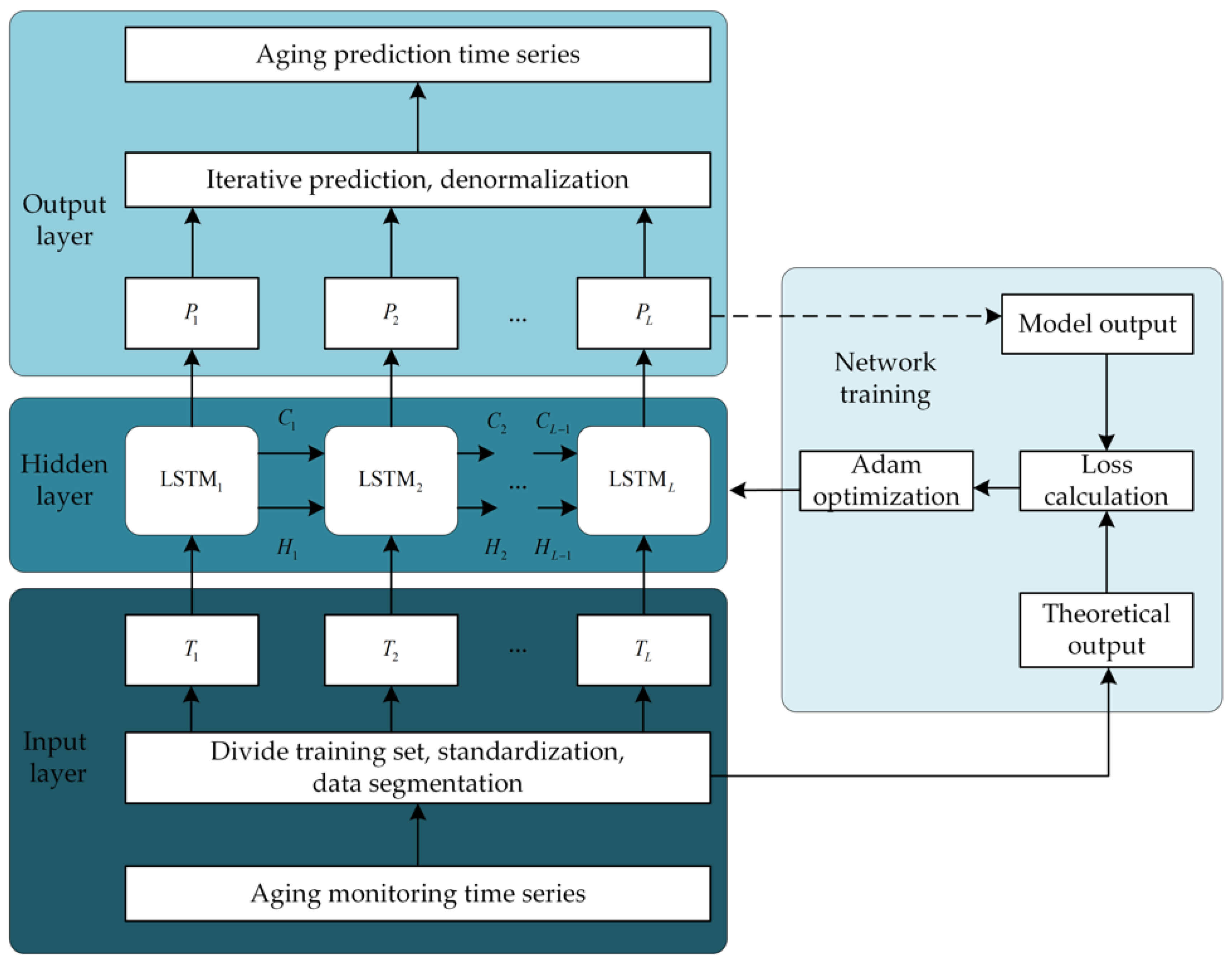
Motivated by the analysis described above, this paper improves the long short-term memory (LSTM) algorithm according to IGBT aging characteristics to obtain the segmented LSTM prediction network. Combined condition monitoring and reliability evaluation, a PoF and DD fusion algorithm is proposed for online reliability evaluation of microgrid inverter IGBT. First, the segmented LSTM accurately predicts the aging state curve of the IGBT based on the limited monitoring data, and the IGBT aging state is judged in real-time. Next, parameters of the electrothermal coupling model are updated to correct the influence of the aging process, which guarantees the junction temperature data is consistent with the actual working conditions. Further, the rainflow counting algorithm makes statistics on the thermal stress distribution via the junction temperature data. Finally, combined with fatigue damage theory and the life prediction model, a reliability evaluation is carried out.
This paper is organized as follows. Section 2 establishes an electrothermal coupling model for the topology of the microgrid inverter and verifies the model by the power loss and junction temperature data of the manufacturer. Section 3 illustrates IGBT fatigue damage theory and accelerated aging experiments, and studies the segmented LSTM prediction network suitable for the IGBT aging process. Section 4 introduces the proposed fusion algorithm flow and analyzes an actual case via the fusion algorithm. Verification and comparison are presented in Section 5. Section 6 draws the conclusion.

2. IGBT Reliability Modeling

2.1. Electrothermal Coupling Model

Bonding wire peeling and solder layer cracking are two main failure modes of IGBTs, which mainly caused the junction temperature inside the device [29]. Therefore, the junction temperature is the crucial data to study the performance degradation and reliability analysis of microgrid inverter IGBTs. Figure 1 illustrates the flow chart of establishing the electrothermal coupling model, which can output real-time junction temperature data. The IGBT power loss model is derived by combining the microgrid inverter topology and IGBT operating characteristics. The equivalent model of the IGBT thermal network is derived based on the physical structure of the IGBT module and the internal heat conduction process. Eventually, the real-time junction temperature fluctuation data of the IGBT under the current operating conditions can be output.
Set the DC side voltage to 1100 V, the external ambient temperature to 50 ℃, the switching frequency to 10 kHz, and the duty cycle to 0.4. The electrothermal coupling model refers to the IRG4BC30K IGBT datasheet, which is produced by Infineon. In Table 1, compared with the data output by the Infineon-IGBT simulation tool under the same conditions, the model is verified by power loss and junction temperature.

2.2. Life Prediction Model

In order to evaluate the reliability and life of IGBT modules, manufacturers and researchers generally carry out accelerated aging tests and put forward a series of IGBT module life models based on test data and failure mechanisms, such as the Lesit model, Bayerer model, and Coffin–Manson model.
  • The Lesit model considers both the junction temperature fluctuation and the average value, and its mathematical expression is:
    N f = A · ( T j ) α · exp ( E α k · T m )
    where A is the model correction coefficient,   α is the junction temperature fluctuation index, k is the Boltzmann constant, and E α   is the excitation energy of the IGBT module chip [30].
  • The Coffin–Manson model involves three factors: maximum temperature, junction temperature fluctuation, and cycle frequency [31]. Its mathematical expression is:
    N f = A · f   a · ( T j ) b · G ( T m )
    where A is the fitting constant, a is the cycle frequency index (typical value is about 1/3), and b is the junction temperature fluctuation index (standard value is about 2).
  • The Bayerer model takes many other variables into account, in addition to the maximum junction temperature and junction temperature fluctuations considered by the Coffin–Manson model. Its mathematical expression is:
    N f = K · ( T j ) β 1 · e β 2 T jmax + 273 · t on β 3 · I β 4 · V β 5 · D β 6
    where K is the model correction coefficient, β 1 β 2   is the junction temperature fluctuation index and the maximum junction temperature index, and β 3 β 6   is the power cycle heating time, the device withstand voltage rating, the bonding wire current, and the index of the bond wire diameter [32].
Currently, the Lesit model is mostly applied in the life prediction of IGBT life. Its expression is simple and consistent with the results of the aging experiment. Moreover, it has an excellent online monitoring capability in conjunction with rainflow counting. Although the Bayerer model is more accurate than other models, it is impossible to apply to online monitoring due to many parameters being difficult to measure.

3. IGBT Aging Monitoring

3.1. Fatigue Damage Theory

IGBT needs to withstand a large number of thermal stress cycles during operation. Assume that Nf is the number of failure cycles of the IGBT under a stress cycle with constant amplitude. When the number of cycles that it bears the stress cycle is N (N is less than Nf), the fatigue damage of the IGBT can be expressed by the cumulative damage degree as follows [33]:
D = N N f
If the device endures multiple constant amplitude stresses, and the number of impacts generated by each constant amplitude stress is Ni, the cumulative damage degree can be expressed as follows:
D = i = 1 k D i = i = 1 k N i N f ,   i
when the cumulative damage D reaches 1, it indicates that the device fails due to fatigue damage. In the actual working process of the microgrid inverter, the solder layer of the IGBT is prone to fatigue damage, and the thermal resistance increases with the aging process of the device material. Due to the influence of the IGBT aging process on the life prediction, it is necessary to update the thermal network parameters of the electrothermal coupling model in time. According to the aging law of the IGBT module, increasing the thermal model parameters by 10%–50% can simulate different aging stages [34].

3.2. Accelerated Aging Test

Since the aging process of IGBT is very long, in order to obtain relatively accurate aging data in a short time, it is necessary to conduct an accelerated aging test on IGBT. During the experiment, the device is in a state of high-speed switching, so the device can withstand a large number of thermal stress cycles in a short time, which accelerates the aging failure. The aging process of IGBT will change the electrical parameters, so parameters measured easily can be selected to predict the aging process of IGBT. Among these parameters, collector–emitter voltage is the most suitable precursor for aging prognostic, considering online measurement, calibration, accuracy, linearity, and sensitivity [26]. When IGBT is turned off, parasitic transistors produce a transient voltage, which interacts with the IGBT collector voltage to produce the transient peak voltage in Figure 2a. The analysis of aging data in the National Aeronautics and Space Administration (NASA) laboratory shows that the collector–emitter peak voltage (Vce_peak) is closely related to the degradation, so Vce_peak can be employed to monitor the aging process of IGBT.
This paper uses the accelerated aging experimental data set published by NASA Prognostics Center of Excellence (PCoE) to study the aging prediction network model and apply the best model in the actual example [35]. The experimental platform of the NASA accelerated aging test for IRG4BC30K is shown in Figure 2b, and the test parameters are listed in Table 2. Therefore, the setting of the accelerated aging test is very close to the actual working condition of IGBT. The parameters measured by the accelerated aging experiment contain collector current, collector–emitter voltage, gate voltage, and packaging temperature. Vce_peak was sampled and extracted to obtain the aging monitoring data set until the device failed.

3.3. Segmented LSTM Algorithm

In recent years, with the continuous development of deep learning (DL), relevant models are gradually applied to fault time series data. DL is a kind of deep neural network model with multiple nonlinear mapping levels, which can abstract and extract features of input signals layer by layer and dig out more profound potential laws [36]. As one of the DL networks, having the inherent potential of fully mining the data time-series information, a recurrent neural network (RNN) has been widely used in time series prediction [37]. A convolution neural network (CNN) can also achieve the purpose of time series prediction by constructing samples, but vast amounts of data are needed, which cannot match the aging characteristics of IGBTs.
RNN introduces the concept of a time sequence into the design of a network structure, making it more adaptable in the analysis of time-series data. However, RNN has many disadvantages, such as gradient disappearance, gradient explosion, and reduced long-term memory. As an improved model of RNN, LSTM can make up for the shortcomings of RNN. IGBTs can be affected by factors such as high temperature, high pressure, and harsh environment during the working process. Besides, its continuous stress impact will cause fatigue damage to the device. Therefore, the IGBT aging state gradually changes with time, which indicates that the current device aging state will be affected by the previous one. So, IGBTs aging prediction can be abstracted as a time series prediction problem.
In real projects, the monitoring device cannot collect a large amount of aging data in a short time, which is not conducive to real-time evaluation of the aging state of IGBTs. The LSTM algorithm can predict the aging process of IGBT according to the monitoring data. The prediction framework is shown in Figure 3, and the parameter settings are listed in Table 3. The first 25% of the data set was used as training data to train the LSTM time series prediction network, and the remaining 75% data verified the prediction results in Figure 4. It can be found that the forecast data in the early stage coincided with the observed value, but the forecast data in the later stage deviated far from the observed data. Finally, the root mean squared error (RMSE) of the LSTM prediction was 0.27824.
In response to this problem, this paper proposed a segmented LSTM prediction algorithm, and the flowchart is illustrated in Figure 5. During the first LSTM prediction, the first 1/3 data of the prediction data (P1) was retained and combined with the original training data (T1) to form the training data of the second LSTM prediction (T2). During the second LSTM prediction in Figure 6, the first 1/2 of the prediction data (P2) and T2 were combined into the training data set for the third LSTM prediction (T3). During the third LSTM prediction shown in Figure 7, all aging prediction data (P3) was consistent with the measured data. After three-segmented LSTM predictions, the final comparison of prediction data and monitoring data is presented in Figure 8, and the RMSE was only 0.1153. The segmented LSTM algorithm had higher prediction accuracy under the condition of limited training data, which meets the needs of microgrid inverter IGBT condition monitoring and reliability analysis.

4. IGBT Reliability Online Evaluation Fusion Algorithm

4.1. Algorithm Flow

As shown in Figure 9, the framework of the online reliability evaluation fusion algorithm proposed in this paper consisted of three parts. The first part is the reliability analysis based on PoF. The influence of wind speed and ambient temperature is considered through SCADA data, and then the wind turbine model and electrothermal coupling model are used to obtain real-time junction temperature data. The second part is the DD condition monitoring. Vce_peak monitoring data is used for segmented LSTM prediction to estimate the aging process of IGBT. According to the obtained aging curve, the thresholds of different aging stages are divided. Compare the threshold and monitoring data to determine the aging stage in real-time, and select the corresponding electrothermal coupling model, which considers the impact of the aging process and improves the accuracy of microgrid IGBT reliability assessment. The third part is the life prediction. The junction temperature fluctuation data is processed by the rainflow counting algorithm to obtain the distribution of the fluctuation amplitude and mean value. In the end, the Lesit life prediction model could efficiently use the output data of the rainflow counting algorithm and combine fatigue damage theory for life prediction.

4.2. Case Analysis

In order to show the working principle of the fusion algorithm more clearly, this paper took the wind power generation system in the microgrid as an example (specific parameters are listed in Table 4) and analyzed the reliability of its inverter IGBT. The wind speed and ambient temperature recorded in the SCADA database within one year were imported into the wind turbine model and the electrothermal coupling model to derive the real-time junction temperature curve of the inverter IGBT. Meanwhile, the segmented LSTM algorithm predicted the aging process through the monitoring data of Vce_peak. Perform zero-order retention and averaging of aging data to extract more obvious aging trends. The estimated aging process is presented in Figure 10, and the thresholds for different aging stages are enlisted in Table 5.
Compare the threshold value and the monitoring data to determine the aging stage of the IGBT in real-time, and then select the corresponding aging correction factor in Table 5. Substitute the aging correction coefficient into the thermal resistance update equation to update the thermal network parameters of the electrothermal coupling model, which ensures the accuracy of the junction temperature data. The thermal resistance update equation is as follows:
R = R initial ( 1 + a · r m )
where Rinitial is the initial value of thermal resistance, a is the aging factor (typical value is about 0.5), r is the aging process coefficient (regular value is 0–1), and m is temperature stress factor (standard value is 1) [38].
After the above steps, the junction temperature data after aging correction can be obtained. As shown in Figure 11, the rainflow counting method was used to extract the mathematical distribution of junction temperature fluctuation T j and the average value of junction temperature Tm, which are the critical data for the next reliability evaluation and life prediction. Compared with the uncorrected junction temperature data, the corrected junction temperature data was more in line with the actual working conditions, and the thermal stress load distribution obtained accordingly was more accurate.
Finally, the Lesit life prediction model was used to predict the maximum number of thermal stress cycles Nf, i that the aging IGBT can withstand under various operating conditions, and then the cumulative damage and estimated life of IGBT were calculated with Equation (5).

5. Comparison and Verification

Previously, the proposed fusion algorithm has been used to evaluate the reliability of the microgrid inverter IGBT. In order to fully explain the advantages of the proposed fusion algorithm for online evaluation of IGBT reliability, which combines PoF reliability analysis with DD condition monitoring, the results of a health assessment were first compared with historical statistical data. Then, the life prediction results were compared with that of other correction algorithms.
In order to study the reliability of IGBTs, scientific research institutions and scholars have made statistics on the failure and damage causes of a large number of IGBTs. Table 6 lists the average cumulative damage degree statistics for the same type of IGBT in one year. View the weighted average cumulative damage and life prediction results as the mathematical expectation of the evaluation results.

5.1. Comparison and Verification of a Health Assessment

This paper used DL algorithms (LSTM), traditional time series prediction algorithms (ARIMA), and the proposed algorithm (the segmented LSTM) to predict the aging of the monitoring data, and make aging corrections in the process of reliability evaluation. Table 7 shows a comparison of the results of aging correction using different prediction algorithms. Without aging correction, the cumulative damage error reached 45.51%, which overestimated the IGBT health status. After aging correction based on the actual aging parameter observation data, the cumulative damage error was only 3.88%, which indicates the effectiveness of the fusion algorithm. It can be found that monitoring the aging state and updating the parameters of the electrothermal coupling model in time could significantly improve the accuracy of the reliability evaluation.
Compared with the LSTM algorithm and ARIMA algorithm, the segmented LSTM algorithm could predict the aging process of IGBT more accurately, and the cumulative damage error after correction was only 5.10%. Thus, the fusion algorithm based on the segmented LSTM still had excellent adaptability in the case of insufficient monitoring data. The fusion algorithm could effectively correct the influence of the aging process on the reliability evaluation of the IGBT, and the evaluation result could genuinely reflect the health status of the IGBT.

5.2. Comparison and Verification of Life Prediction

In the existing literature, some correction methods have been tried to predict the life of the same type of inverter IGBT. The expected life span is between 17.71 and 28.50 years. The predicted lifetime obtained by the fusion algorithm proposed in this paper is 22.22 years, which is consistent with the prediction results of the existing literature. So as to compare the accuracy of each correction algorithm, the errors between the life prediction results and the mathematical expectation are calculated in Table 8. The prediction error of the fusion algorithm is only 5.83%, which is far lower than other correction algorithms. Therefore, the fusion algorithm based on the segmented LSTM can correctly predict the life of the IGBT based on its health status.

6. Conclusions

This paper proposed an online IGBT reliability evaluation fusion algorithm for microgrid inverters, which combined the PoF reliability analysis with DD condition monitoring to eliminate the influence of aging on a reliability analysis. For solving the contradiction between the IGBT aging cycle and observation scale, the segmented LSTM algorithm was studied on the framework of the original LSTM algorithm. Based on limited aging monitoring data, it could accurately predict the aging process of the device and judge the aging stage, which is the basis for real-time updating of the electrothermal coupling model parameters. The case analysis shows that the combination of condition monitoring and reliability analysis dramatically improved the accuracy of the assessment. In the case of limited monitoring data in actual projects, segmented LSTM can more accurately correct the impact of the IGBT aging process than other traditional algorithms. Statistical data and algorithm comparison verify the feasibility and superiority of the fusion algorithm. The proposed fusion algorithm reduces the dependence on the length of the monitoring data time series and improves the accuracy of reliability evaluation, which meets the requirements of the online reliability evaluation.

Author Contributions

Conceptualization, methodology, software, validation, formal analysis, investigation, resources, C.W. (Chuankun Wang) and Y.H.; Data curation writing—original draft preparation, C.W. (Chenyuan Wang); Writing—review and editing, X.W.; Visualization, L.L. All authors have read and agreed to the published version of the manuscript.

Funding

This research was supported by the National Natural Science Foundation of China (Grant No. 51977153, 51977161, and 51577046), the State Key Program of National Natural Science Foundation of China (Grant No. 51637004), the national key research and development plan “important scientific instruments and equipment development” of China (Grant No.2016YFF0102200), the Equipment research project in advance of China (Grant No.41402040301).

Conflicts of Interest

The authors declare no conflict of interest.

References

  1. Bani-Ahmed, A.; Rashidi, M.; Nasiri, A.; Hosseini, H. Reliability analysis of a decentralized microgrid control architecture. IEEE Trans. Smart Grid. 2019, 10, 3910–3918. [Google Scholar] [CrossRef]
  2. Bahramirad, S.; Reder, W.; Khodaei, A. Reliability-Constrained optimal sizing of energy storage system in a microgrid. IEEE Trans. Smart Grid. 2012, 3, 2056–2062. [Google Scholar] [CrossRef]
  3. Choi, U.; Blaabjerg, F.; Jørgensen, S.; Munk-Nielsen, S.; Rannestad, B. Reliability improvement of power converters by means of condition monitoring of IGBT modules. IEEE Trans. Power Electron. 2017, 32, 7990–7997. [Google Scholar] [CrossRef]
  4. Sangwongwanich, A.; Yang, Y.; Sera, D.; Blaabjerg, F. Mission profile-oriented control for reliability and lifetime of photovoltaic inverters. IEEE Trans. Ind. Appl. 2019, 56, 601–610. [Google Scholar] [CrossRef] [Green Version]
  5. Choi, U.; Blaabjerg, F.; Lee, K. Study and handling methods of power IGBT module failures in power electronic converter systems. IEEE Trans. Power Electron. 2015, 30, 2517–2533. [Google Scholar] [CrossRef]
  6. Choi, J.; Khalsa, A.; Klapp, D.A.; Baktiono, S.; Illindala, M.S. Survivability of prime-mover powered inverter-based distributed energy resources during microgrid islanding. IEEE Trans. Ind. Appl. 2019, 55, 1214–1224. [Google Scholar] [CrossRef]
  7. Oh, H.; Han, B.; McCluskey, P.; Han, C.; Youn, B.D. Physics-of-failure, condition monitoring, and prognostics of insulated gate bipolar transistor modules: A Review. IEEE Trans. Power Electron. 2015, 30, 2413–2426. [Google Scholar] [CrossRef]
  8. Sabbah, W.; Arabi, F.; Avino-Salvado, O.; Buttay, C.; Théolier, L.; Morel, H. Lifetime of power electronics interconnections in accelerated test conditions: High temperature storage and thermal cycling. Microelectron. Reliab. 2017, 76, 444–449. [Google Scholar] [CrossRef] [Green Version]
  9. Eleffendi, M.A.; Johnson, C.M. Application of Kalman filter to estimate junction temperature in IGBT power modules. IEEE Trans. Power Electron. 2016, 31, 1576–1587. [Google Scholar] [CrossRef]
  10. Musallam, M.; Johnson, C.M. Real-Time compact thermal models for health management of power electronics. IEEE Trans. Power Electron. 2010, 25, 1416–1425. [Google Scholar] [CrossRef]
  11. Van der Broeck, C.H.; Lorenz, R.D.; De Doncker, R.W. Monitoring 3-D Temperature Distributions and Device Losses in Power Electronic Modules. IEEE Trans. Power Electron. 2019, 34, 7983–7995. [Google Scholar] [CrossRef]
  12. Wang, X.; Li, Z.; Yao, F.; Tang, S. Simplified estimation of junction temperature fluctuation at the fundamental frequency for IGBT modules considering mission profile. IEEE Access 2019, 7, 149308–149317. [Google Scholar] [CrossRef]
  13. GopiReddy, L.R.; Tolbert, L.M.; Ozpineci, B.; Pinto, J.O.P. Rainflow algorithm-based lifetime estimation of power semiconductors in utility applications. IEEE Trans. Power Electron. 2019, 51, 3368–3375. [Google Scholar] [CrossRef]
  14. Hu, Z.; Du, M.; Wei, K.; Hurley, W.G. An adaptive thermal equivalent circuit model for estimating the junction temperature of IGBTs. IEEE J. Emerg. Sel. Top. Power Electron. 2019, 7, 392–403. [Google Scholar] [CrossRef]
  15. Astigarraga, D.; Ibanez, F.M.; Galarza, A.; Echeverria, J.M.; Unanue, I.; Baraldi, P.; Zio, E. Analysis of the results of accelerated aging tests in insulated gate bipolar transistors. IEEE Trans. Power Electron. 2016, 31, 7953–7962. [Google Scholar] [CrossRef]
  16. Mohamed Sathik, M.H.; Sundararajan, P.; Sasongko, F.; Pou, J.; Natarajan, S. Comparative analysis of IGBT parameters variation under different accelerated aging tests. IEEE Trans. Electron. Devices 2020, 67, 1098–1105. [Google Scholar] [CrossRef]
  17. Singh, A.; Anurag, A.; Anand, S. Evaluation of Vce at inflection point for monitoring bond wire degradation in discrete packaged IGBTs. IEEE Trans. Power Electron. 2017, 32, 2481–2484. [Google Scholar] [CrossRef]
  18. Hu, Z.; Zhang, W.F.; Wu, J. An improved electro-thermal model to estimate the junction temperature of IGBT module. Electronics 2019, 8, 1066. [Google Scholar] [CrossRef] [Green Version]
  19. Mandeya, R.; Chen, C.; Pickert, V.; Naayagi, R.T.; Ji, B. Gate-Emitter pre-threshold voltage as a health-sensitive parameter for IGBT chip failure monitoring in high-voltage multichip IGBT power modules. IEEE Trans. Power Electron. 2018, 34, 9158–9169. [Google Scholar] [CrossRef] [Green Version]
  20. Sun, P.; Gong, C.; Du, X.; Peng, Y.; Wang, B.; Zhou, L. Condition monitoring IGBT module bond wires fatigue using short-circuit current identification. IEEE Trans. Power Electron. 2017, 32, 3777–3786. [Google Scholar] [CrossRef]
  21. Zhu, P.; Chen, B.; Prı´ncipe, J.C. Learning nonlinear generative models of time series with a Kalman filter in RKHS. IEEE Trans. Signal Process. 2014, 62, 141–155. [Google Scholar] [CrossRef]
  22. Patil, N.; Das, D.; Pecht, M. A prognostic approach for non-punch through and field stop IGBTs. Microelectron. Reliab. 2012, 52, 482–488. [Google Scholar] [CrossRef]
  23. Brown, D.; Kalgren, P.; Roemer, M. Electronic Prognostics—A Case Study Using Switched-Mode Power Supplies (SMPS). IEEE Instrum. Meas. Mag. 2007, 10, 20–26. [Google Scholar] [CrossRef]
  24. Li, R.; Verhagen, W.J.C.; Curran, R. A comparative study of Data-driven Prognostic Approaches: Stochastic and Statistical Models. In Proceedings of the IEEE International Conference on Prognostics and Health Management (ICPHM), Seattle, WA, USA, 11–13 June 2018; pp. 1–8. [Google Scholar] [CrossRef]
  25. Ahsan, M.; Stoyanov, S.; Bailey, C. Data driven prognostics for predicting remaining useful life of IGBT. In Proceedings of the 39th International Spring Seminar on Electronics Technology (ISSE), Pilsen, Czech Republic, 18–22 May 2016; pp. 273–278. [Google Scholar] [CrossRef] [Green Version]
  26. Zheng, Z.; Peng, J.; Deng, K.; Gao, K.; Li, H.; Chen, B.; Yang, Y.; Huang, Z. A Novel Method for Lithium-Ion Battery Remaining Useful Life Prediction Using Time Window and Gradient Boosting Decision Trees. In Proceedings of the 10th International Conference on Power Electronics and ECCE Asia (ICPE 2019-ECCE Asia), Busan, Korea, 27–30 May 2019; pp. 3297–3302. [Google Scholar]
  27. Wei, J.; Dong, G.; Chen, Z. Remaining Useful Life Prediction and State of Health Diagnosis for Lithium-Ion Batteries Using Particle Filter and Support Vector Regression. IEEE Trans. Ind. Inform. 2018, 65, 5634–5643. [Google Scholar] [CrossRef]
  28. Fang, X.; Lin, S.; Huang, X.; Lin, F.; Yang, Z.; Igarashi, S. A review of data-driven prognostic for IGBT remaining useful life. Chin. J. Electron. 2018, 4, 73–79. [Google Scholar] [CrossRef]
  29. .Zhang, J.; Du, X.; Wu, Y.; Luo, Q.; Sun, P.; Tai, H. Thermal parameter monitoring of IGBT module using case temperature. IEEE Trans. Power Electron. 2019, 34, 7942–7956. [Google Scholar] [CrossRef]
  30. Held, M.; Jacob, P.; Nicoletti, G.; Scacco, P.; Poech, M.H. Fast power cycling test for insulated gate bipolar transistor modules in traction application. Int. J. Electron. 1999, 86, 1193–1204. [Google Scholar] [CrossRef]
  31. Cui, H. Accelerated temperature cycle test and Coffin-Manson model for electronic packaging. In Proceedings of the Annual Reliability and Maintainability Symposium, Alexandria, VA, USA, 24–27 January 2005; pp. 556–560. [Google Scholar] [CrossRef]
  32. Bayerer, R.; Herrmann, T.; Licht, T.; Lutz, J.; Feller, M. Model for power cycling lifetime of IGBT Modules—Various factors influencing lifetime. In Proceedings of the 5th International Conference on Integrated Power Electronics Systems, Nuremberg, Germany, 11–13 March 2008; pp. 1–6. [Google Scholar]
  33. Choi, U.; Ma, K.; Blaabjerg, F. Validation of lifetime prediction of IGBT modules based on linear damage accumulation by means of superimposed power cycling tests. IEEE Trans. Power Electron. 2018, 65, 3520–3529. [Google Scholar] [CrossRef]
  34. Chen, M.; Chen, Y.; Gao, B.; Lai, W.; Xu, S. Lifetime evaluation of IGBT module considering fatigue accumulation of solder layers. Proc. CSEE 2018, 38, 6053–6061. [Google Scholar] [CrossRef]
  35. NASA Ames Research Center. Available online: https://ti.arc.nasa.gov/tech/dash/groups/pcoe/prognostic-data-repository/#igbt (accessed on 2 May 2020).
  36. Chen, B.; Liu, Y.; Zhang, C.; Wang, Z. Time series data for equipment reliability analysis with deep learning. IEEE Access 2020, 8, 105484–105493. [Google Scholar] [CrossRef]
  37. Hajiabotorabi, Z.; Kazemi, A.; Samavati, F.F.; Ghaini, F.M.M. Improving DWT-RNN model via B-spline wavelet multiresolution to forecast a high-frequency time series. Expert Syst. Appl. 2019, 138, 112842. [Google Scholar] [CrossRef]
  38. Lai, W.; Chen, M.; Ran, L.; Alatise, O.; Xu, S.; Mawby, P. Low ΔTj stress cycle effects in IGBT power module die-attach lifetime modeling. IEEE Trans. Power Electron. 2016, 31, 6575–6585. [Google Scholar] [CrossRef]
  39. Chung, H.; Wang, H.; Blaabjerg, F.; Pecht, M. Reliability of Power Electronic Converter Systems; The Institution of Engineering and Technology: London, UK, 2015; pp. 174–187. ISBN 978-1-84919-901-8. [Google Scholar]
  40. Carroll, J.; Mcdonald, A.; Mcmillan, D. Reliability comparison of Wind Turbines with DFIG and PMG drive trains. IEEE Trans. Energy Convers. 2015, 30, 663–670. [Google Scholar] [CrossRef] [Green Version]
  41. Fischer, K.; Pelka, K.; Bartschat, A.; Tegtmeier, B.; Coronado, D.; Broer, C. Reliability of power converters in wind turbines: Exploratory analysis of failure and operating data from a worldwide turbine fleet. IEEE Trans. Power Electron. 2019, 34, 6332–6344. [Google Scholar] [CrossRef]
  42. Wang, H.; Liserre, M.; Blaabjerg, F.; de Place Rimmen, P.; Jacobsen, J.B.; Kvisgaard, T.; Landkildehus, J. Transitioning to Physics-of-Failure as a Reliability Driver in Power Electronics. IEEE J. Emerg. Sel. Top. Power Electron. 2014, 2, 97–114. [Google Scholar] [CrossRef]
  43. Huang, H.; Mawby, P.A. A lifetime estimation technique for voltage source converters. IEEE Trans. Power Electron. 2013, 28, 4113–4119. [Google Scholar] [CrossRef]
Figure 1. Electrothermal coupling model
Electronics 09 01294 g001
Figure 2. (a) Collector–emitter turn-off voltage waveform. (b) Insulated gate bipolar transistor (IGBT) accelerated aging experiment platform.
Electronics 09 01294 g002
Figure 3. Aging time series prediction framework based on LSTM.
Electronics 09 01294 g003
Figure 4. The first LSTM prediction.
Electronics 09 01294 g004
Figure 5. The segmented LSTM prediction flowchart.
Electronics 09 01294 g005
Figure 6. The second LSTM prediction.
Electronics 09 01294 g006
Figure 7. The third LSTM prediction.
Electronics 09 01294 g007
Figure 8. The result of the segmented LSTM prediction.
Electronics 09 01294 g008
Figure 9. Flowchart of the reliability evolution fusion algorithm.
Electronics 09 01294 g009
Figure 10. IGBT aging process.
Electronics 09 01294 g010
Figure 11. (a) Uncorrected thermal stress load distribution. (b) Corrected thermal stress load distribution. (c) Observed thermal stress load distribution.
Electronics 09 01294 g011
Table 1. Electrothermal coupling model verification.
Verify ContentIGBT Switching Loss (W)IGBT Conduction Loss (W)Junction Temperature (℃)
Infineon-IGBT simulation tool8.0107.68268.83
Electrothermal coupling model8.2767.79969.81
Error3.32%1.52%1.42%
Table 2. Accelerated aging test parameters.
TypesSetting
IGBT typeIRG4BC30K
PWM duty cycle0.4
Switching frequency (kHz)10
Package temperature (℃)260–270
Gate voltage (V)10
Table 3. Hyperparameter settings of long short-term memory (LSTM) networks.
TypesSetting
Initial Learn Rate0.001
Learn Rate Schedulepiecewise
Max Epochs50
Gradient Threshold1
Learn Rate Drop Period25
Learn Rate Drop Factor0.1
Execution environmentGPU
OptimizerAdam
Verbose0
Table 4. Wind power system parameters.
TypesParameters
Rated power (kW)20
Cut-in wind speed (m/s)3
Rated wind speed (m/s)11
Cut out wind speed (m/s)25
Grid-side voltage (V)690
DC side voltage (V)1100
Grid-side frequency (Hz)50
IGBT switching frequency (kHz)10
IGBT TypeIRG4BC30K
Table 5. The threshold voltage of IGBT aging stages.
Threshold VoltageForecast (V)Observed (V)Aging Correction Factor
Health status 10.32310.323-
Aging stage 19.9399.9270.2
Aging stage 29.5549.5320.4
Aging stage 39.1709.1340.6
Aging stage 48.7868.7410.8
Aging stage 5 8.4028.3461.0
Table 6. Historical statistics of IGBT cumulative damage.
Data SourcesYearNumber of SamplesCumulative Damage Degree
WMEP [39]1998–20002090.189
1989–200610280.085
LWK [39]1993–200657190.042
CARROLL [40]2005–201091100.020
FISCHER [41]2003–201723160.150
Table 7. Comparison of health assessment.
Algorithm TypeCumulative DamageError
Mathematical Expectation0.0490-
No correction0.026745.51%
Observation data correction0.04713.88%
Segmented LSTM0.04655.10%
LSTM0.039818.78%
ARIMA0.034130.41%
Table 8. Comparison of life prediction.
Algorithm TypeLife Perdition (Year)Error
Mathematical Expectation20.408-
Proposed fusion Algorithm21.5985.83%
Multiple PoF algorithm [42]22.0007.80%
Segmented network
update algorithm [43]
28.50039.65%
Single PoF algorithm [34]17.71022.63%

