1. Introduction
In recent decades, the embedded processors have been broadly utilized in various fields, such as modern industry, the military, and agriculture. However, it has been reported that numerous embedded systems suffer from potential security risks [
1], including transient fault [
2], hardware Trojan (HT) [
3,
4], buffer overflow vulnerabilities [
5], distributed denial-of-service [
6,
7], side-channel attacks [
8,
9], and cloning attacks [
10]. These undesired attacks would result in grave consequences covering system function changes, information leakages, service crashes, and even system damages. For the security of embedded processors, it is necessary to effectively and efficiently deal with the security issues mentioned above.
The security attack evolves with the rapid development of embedded processors, which implies that it is never simple and straightforward to address these unwanted attacks. Based on the attack targets, common attacks could be generally classified into three groups: tampering with program, modifying dynamic data, and illegal monitoring. The consequences of these malicious actions are rather more serious than one would think. Especially, tampering with the program could directly damage the normal behavior of the embedded system. There are many kinds of dangerous attacks that can lead to malicious tampering with the executed code. For example, the buffer overflow attack not only modifies the return address, but also inserts a malicious shellcode to achieve the attack purpose. This article aims to carry out the monitoring and recovery operations based on the fact that the code being monitored has already been tampered. Briefly, the generic detections belonging to this group could be further divided into two kinds: software-based and hardware-based methods.
Software-based detections largely adopt static analysis and dynamic software monitor technology to detect attacks. The former methods firstly take advantage of the security analysis tools to scan source codes of program, and then compare them with predefined vulnerability files to test the program flaws [
11,
12]. Since there is less information of running time, this approach should not be capable of preventing all the known vulnerabilities and transient faults. The latter technology develops several algorithms to modify operating system or run external software to detect code security at runtime [
13,
14], which unfortunately upgrades the difficulty of program development and also degrades the processor performance.
In comparison, the hardware-based technologies mainly customize the secure monitoring circuits to scan real-time binary codes of executing instructions, which could be easily integrated into the system on Chip (SoC) during the design of processor [
15,
16]. Moreover, with the help of hardware, these hardware-dependent methods would detect real-time programs without occupying many processor resources. Therefore, the hardware-based attack detection is relatively preferred and sets a foundation for our study here.
Generally speaking, a well-developed fault recovery strategy could cooperate with the monitoring circuit to realize a complete security protection strategy. Among the existing recovery strategies, the checkpoint backup and rollback technology is the most frequently used mechanism [
17], which periodically saves the state of executing program to a file (a checkpoint) to recover that state after a failure. However, most checkpoints suffer from lower real-time performance and have higher requirement for processors and memory resources. In addition, hardware-based attack detection and fault recovery are usually researched separately, where a proper combination of them would increase the ability to deal with embedded processor’s attacks and transient faults.
In this article, we take the executing instructions as the main objects of protection, and focus on analyzing the behavior of executed instructions which were tampered by transient faults, hardware trojans, and buffer overflow attacks. At the same time, the monitoring circuit and the recovery circuit are combined to form a complete embedded security architecture to resist real-time malicious tampering of executing code, as well as ensure the smooth execution of the program. The overall architecture comprises two parts: a security monitoring unit (SMU) and a fault recovery unit (FRU). Here, the SMU considers the fine-grained code integrity verification technology using basic block (BB) as the smallest execution unit, where the implementation of this technology is well optimized for better performance. The FRU is mainly used to complete the backup and rollback of checkpoint. The result of the BB integrity check in the SMU is used as the discrimination signals for the checkpoint backup and rollback in FRU. Besides, an embedded processor recovery mechanism is proposed based on two-stage checkpoints. The specific contributions of this article are as follows:
Expand the BB based extraction method for an effective address in program to improve the searching performance, where a flag “V” is assigned for each BB’s reference information to signify whether the BB is valid or not.
Propose a two-stage checkpoint based backup and recovery mechanism to restore the embedded system from attacks faced on the indirect jump instructions as well as the return address of stack frame.
Provide a system recovery operation from three different dimensions: restoring processor registers, reading instructions from memory, and loading codes from storage.
Design a M-Cache for SMU to reduce the performance overhead of processor, especially for the direct query of BB reference information from memory.
The remainder of this paper is organized as follows. In
Section 2, the works related to hardware-based detection and recovery are introduced briefly.
Section 3 presents the preliminary knowledge about our work.
Section 4 is the analysis of the presented SMU and FRU.
Section 5 provides the utility of proposed architecture under several attack scenarios.
Section 6 evaluates the performance of the proposal and resource consumption.
Section 7 concludes the paper.
2. Related Work
Up to now, a great number of hardware-based methods have been put forward to protect the secure execution of programs under embedded processors, and these methods can be mainly classified into two categories: monitoring-oriented [
18,
19,
20,
21,
22,
23,
24,
25,
26,
27,
28] and recovery-oriented [
29,
30,
31,
32,
33,
34,
35,
36,
37].
The monitoring-oriented technologies usually make use of integrity checking to discover unusual behaviors rather than prevent the external attacks [
38]. In view of programs’ execution security, most existing methods modify the return address within the stack and directly tamper the executing program code. As for the stack security, considerable works consist of shadow call stack (SCS) based on buffer [
19,
20], hardware-assisted flow integrity extension (HAFIX) [
28], and heuristic-based methods such as DROP [
26] and SCRAP [
27]. To detect the real time program tampering, label-based approach and control flow integrity (CFI) were presented one after another. By checking the program’s label identify planted at the beginning of each BB in advanced [
18,
21,
22,
23], the label-based methods supplemented additional codes to the instruction set architecture (ISA). Moreover, the CFI technologies applied a hardware-assisted monitoring structure for run-time codes, and monitored the executing program from three dimensions: inter-procedural and intra-procedural control flow checker, as well as the instruction integrity checker. Especially, the program during the last checker demanded not only BBs ending with explicit control transfer instruction but also a cryptographic hash function to check.
Although many monitoring methods such as those above were proposed to detect whether the system was under attack or not [
38]. However, for ensuring the normal operation of the system, it is not sufficient to detect malicious behavior alone. After discovering the malicious attacks or transient faults, it is critical to support a comprehensive recovery mechanism to provide reliable protection for embedded system.
A majority of the recovery mechanisms rely on the checkpoint backup and rollback schemes. In earlier studies, the system would copy all the registers and Cache data of processor, as well as the data in memory, to the storage, which is devoted to performing rolling back at the moment of system failure [
29]. This simple method not only brings a certain amount of storage overhead, but also greatly reduces the efficiency of the running program, especially when it is applied to a real-time monitoring system. With the purpose of increasing the efficiency of checkpoint backup, Cache and memory-oriented backup and recovery strategies have been proposed in succession [
30,
31,
32,
33]. In addition, methods such as utilizing checkpoint backup intervals and reducing the number of checkpoints are intended to minimize the performance overhead caused by checkpoint backup [
17,
34,
35].
On the basis of these studies, some researchers investigated the combination between the detection of attack behavior and fault restoration. Huu et al. combined the BB integrity check with checkpoint backup and recovery, but the size of the BB was limited within eight instructions caused by the address monitoring table [
37]. Moreover, the backup and recovery of the Cache/memory only considers the attack behaviors occurring at the current BB, and the tampering behavior caused at other times cannot be restored. Chaudhari et al. believed that it is a reasonable opportunity to perform backup after completing the verification for BB and proposed a monitoring and recovery framework based on BB [
39]. In their framework, the identification of BB depended entirely on the jump information in the signature, which contained the starting address of the next BB. All BBs’ signature would be loaded into memory followed by the running of program, and the signatures are accessed by a signature pointer. In view of processor performance, the architecture buffered signatures by using the modified data Cache. However, this approach needed to extract all the flows of program execution in advance, which caused the signature to be very large. Moreover, this method modified a part of the structure of Central Processing Unit (CPU) Core and formed a certain coupling relationship with the processor architecture, which was detrimental to the extension of security architecture.
Different from the above methods, we present a novel approach to identify BB by detecting the jump instruction in the pipeline, and also search the digest of BB based on the target address of the jump instruction from memory. We would construct a new checkpoint for each BB integrity checking, with retaining the last checkpoint to serve the recovery function together. In addition, we design a M-Cache for SMU to reduce the performance loss of processor, which is totally independent of the processor core. What is more, in response to malicious code tampering behavior during execution, the FRU will provide a three-level code recovery strategy to protect the executing program for an embedded processor.
3. Preliminaries
In this section, the essential element of the proposed architecture called BB is introduced in detail. The BB’s extraction method is first elaborated, followed by the preparation of reference information for each BB under the off-line condition.
3.1. Basic Block Extraction
The integrity checking with different code granularity would have diverse effects on the secure execution of the program. A BB is a set of fine-grained codes, which would be achieved by dividing the program into pieces according to specific rules. The traditional method to extract the BBs is by dividing the program with the jump instructions, so that every BB starts with one instruction in the target address from previous jump instruction, and ends with the next jump instruction. In each BB, the instructions are executed sequentially in accordance with their effective addresses without any jump operation until the end. Therefore, the instructions and their executing sequence are fixed for each BB to facilitate the BB-based integrity checking. In addition, if we were familiar with the starting address of a BB in a program, the scope and the instructions of the BB would be uniquely determined. That is why the starting effective address () is deliberately to find the reference information of BB in the article.
Under various processor architectures, the BB extraction methods are different from each other, which are usually caused by numerous specific implementation method of the jump instruction. Within the OR1000 architecture, there is one clock period delay, called delay slot, from executing jump instruction to executing the instruction in the jump target address. Generally, the delay slot is utilized to fill one instruction, which would be executed based on the register value. Therefore, we define a complete BB range that starts with a target instruction from previous jump instruction or the first instruction of program and ends with the instruction in delay slot after the next jump instruction. All instructions in BB are executed orderly, and there is no jump operation except the jump instruction on the border of BB. The extraction for BB is illustrated in
Figure 1.
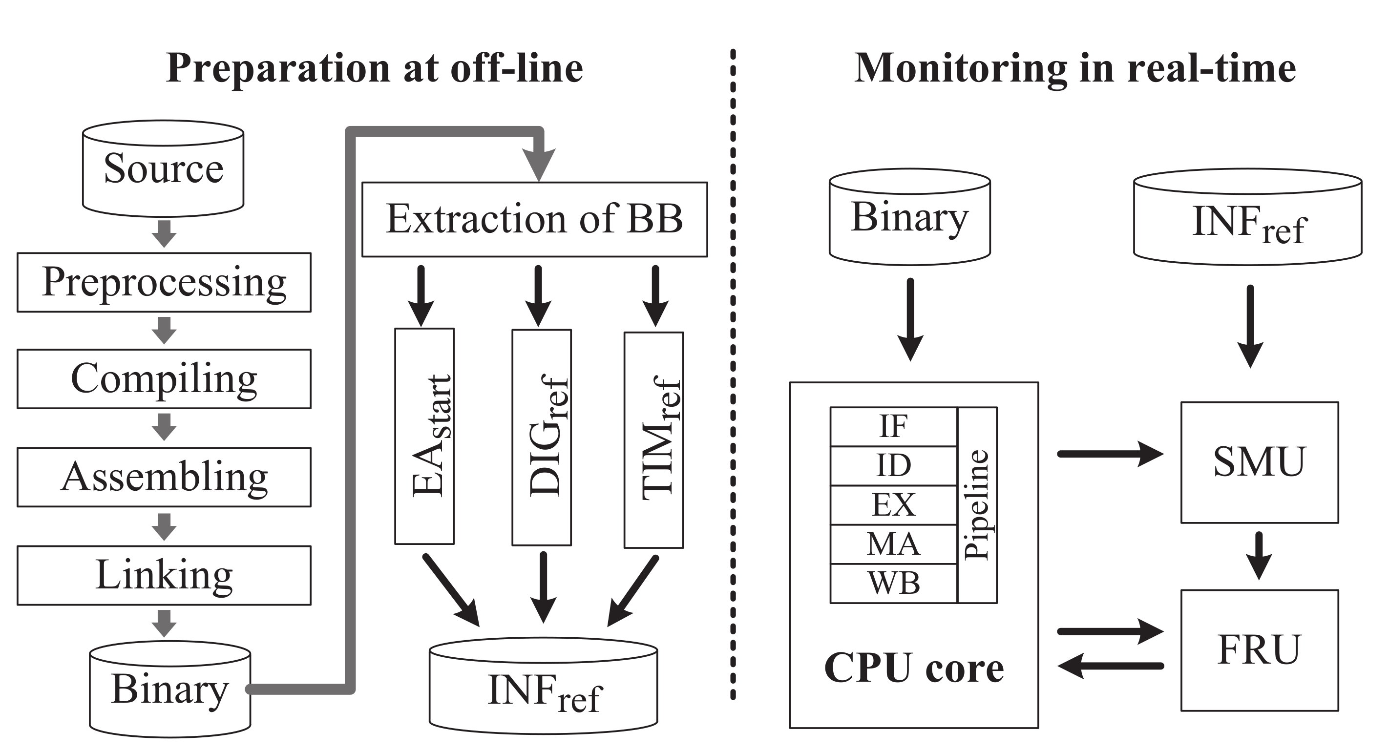
3.2. Reference Information Preparation
When the program is running on a processor, the security architecture will monitor the instructions of each BB by comparing their calculated value in real-time with the corresponding reference value, which was prepared in advanced under off-line condition. The reference value is called a reference information (
) consisting of the
of current BB, the reference digest of BB (
) and the reference running time of BB (
). To be consistent with the reference information, the calculated values should also include the calculated digest (
) and running time (
) for each BB starting with (
). The preparation of reference information involves the extraction of BB, the calculation of
and
, and the generation of
. This preparation process is illustrated in
Figure 2.
The BBs are extracted by disassembling the executable file of the program, finding the jump instructions, and analyzing all possible jump target addresses. The extraction operation is completely independent of the standard compiler and corresponding toolchains, such as GNU Compiler Collection (GCC) and GNU toolchain, because only the ultimate binary file generated by GCC is utilized for analysis. Similarly, is the effective address of the first instruction in BB and used to identify the BB.
is the reference digest of BB and generated by the integrity check algorithm, such as the cyclic redundancy check (CRC) algorithm and the hash function. In [
39], the CRC was used to check the integrity of BB, which did not take into account the collision probability of digest. The hash-oriented integrity checking method is well known for its low collision probability, but the computation is quite complicated. Taking into consideration the constraints of embedded processor resources and other factors, the lightweight hash function (LHash) we proposed previously [
16] is utilized to calculate the digest.
is the calculated digest of BB in run-time and obtained by the same method as
.
The program execution time is another significant parameter for monitoring the program execution, and it is used to judge whether the jump instruction has been tampered with a non-jump instruction by comparing the reference time () with the running time of program (). The is straightly gained by increasing the number of clock cycles for all instructions in a BB. Under the real-time running condition, the could be obtained by counting the number of clock cycles occupied by the instructions of current BB in real-time. Here, some abnormal conditions should be carefully treated by excluding the clock cycles, for instance asserting the CPU_STALL signal to stall the pipeline.
At last, the of each BB is generated by summarizing , , and . All the values are stored into storage based on in ascending order. After the program is executed, all these values are copied into memory for search.
4. Proposed Method
In
Section 3, we introduce the generation of BB reference information under offline conditions. In this section, we elaborate on the hardware structure of proposed security architecture for an embedded processor including the overall structure, two essential components, and the relationship between them.
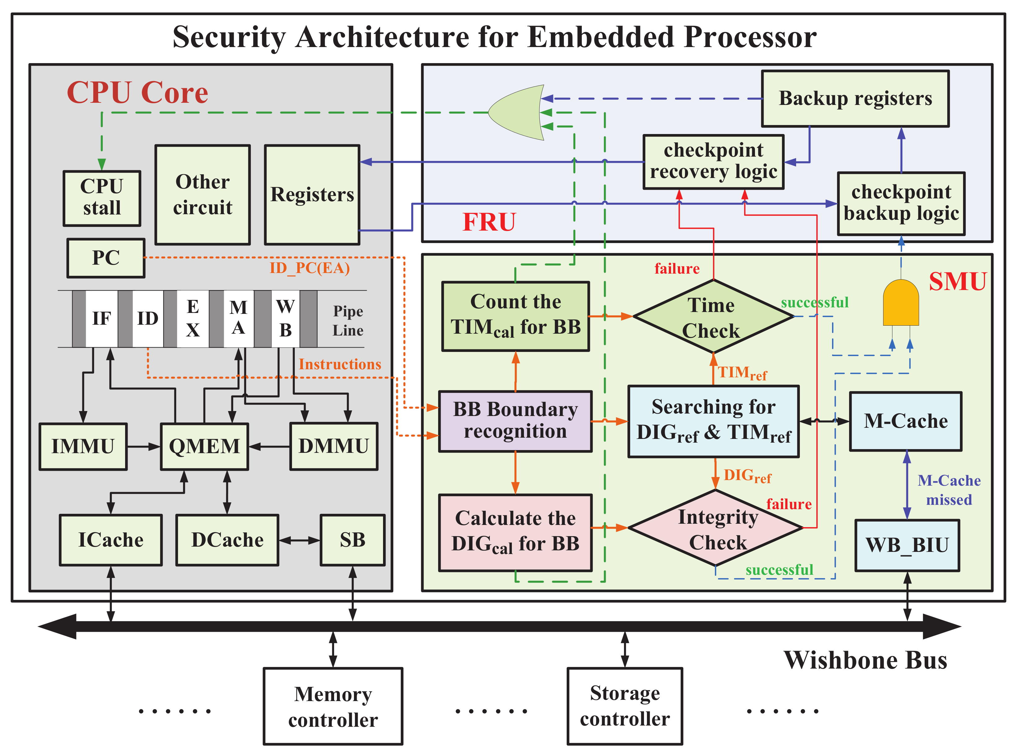
4.1. Overall Structure
The proposed security architecture protects the CPU Core of embedded processor against the tampered code by using an SMU and an FRU (
Figure 3). SMU monitors the executing program of CPU Core in real-time to detect the tampered program. Once SMU notices an abnormal behavior, the FRU attempts to restore the program to ensure the normal operation of the executing program immediately.
For ease of illustration, we choose a reduced instruction set computer (RISC) processor as the CPU Core—OR1200. The processor has an in-order five-stage pipeline consisting of the instruction fetch (IF), the instruction decode (ID), the execution (EX), the memory access (MA), and the write-back (WB). The proposed framework would monitor the program counter (PC) and the instruction register (IR) of OR1200 to safeguard the security of CPU Core.
The SMU is responsible for monitoring the IR and PC value of pipeline in real-time. We could determine the boundary by identifying the jump instruction. With decoding each executing instruction, we adopted a lightweight hash function [
16] to calculate the digest value of current BB denoted as
. Meanwhile, SMU would search the corresponding reference digest (
) from M-Cache or memory according to the
of current BB. The resulting reference digest would be compared with
to check the BB integrity. Similarly, the running time of BB is counted as
in real-time, which is compared with the searched
to detect the malicious modification for jump instructions. If both the digest and the running time are checked successfully, the instructions in BB is considered to be correct. Otherwise, they are regarded as being tampered.
The FRU takes charge of checkpointing and recovery. The executing code and necessary registers in the CPU are stored into backup registers of FRU with the successful integrity checking of BB, which is considered as the best time of checkpointing. Once SMU detects an abnormal execution code, these codes and registers are rolled back from backup registers. Besides the backup registers, we also propose a recovery mechanism to roll back from memory or storage.
4.2. Security Monitoring Unit
To monitor the executing instructions, the SMU should implement four main functions: BB boundary recognition, BB integrity checking, BB running time checking, and reference information searching.
4.2.1. BB Boundary Recognition
It is straightforward to monitor the executing instructions by checking the IR and PC of the pipeline stages. During the process of pipeline, the instruction of the decoding stage is more stable than the one of the fetching stage and appears earlier than one of the other pipeline stages. Therefore, it is reasonable to select the decoding stage IR and corresponding PC as the monitoring object. By analyzing the decoding stage instructions one by one, the boundary of BB would be identified according to the extraction method described in
Section 3.1. Specifically, a complete BB starts with the instruction in the target address from the last jumping and ends with the delay slot instruction after the next jump instruction.
4.2.2. BB Integrity Checking
The integrity checking of BB primarily refers to the BB integrity calculation in real-time to get and the searching of simultaneously. The identical integrity algorithm was used to calculate the digest of BB, either for or . The result of calculating the is compared with that for . If they are equivalent to each other, the instructions in BB can be regarded as normal. Otherwise, the instructions in BB is deemed to be corrupted or tampered during or before execution.
A hash function is a computational method that can map an indeterminate size of data into a fixed size of data. A cryptographic hash function uses one-way mathematical functions which are easy to calculate to generate a hash value from the input, but very difficult to reproduce the input by performing calculations on the generated hash [
40]. Arora utilized the cryptographic hash function to check the instruction integrity [
24]. However, it is quite difficult to implement the traditional hash functions in hardware that would take up plenty of resources. Besides, the output digest value has many bits, such as 128-bit, 160-bit, etc., which is not suitable for fine-grained integrity check in run-time. Therefore, it is necessary to use a hardware friendly and lightweight hash function in SMU to ensure the integrity and security of BB.
Wu proposed the LHash to meet the requirements of low cost and hardware-friendly embedded systems [
41]. LHash employs a kind of Feistel-PG structure in the internal permutation and utilizes permutation layers on nibbles to accelerate the diffusion speed. The low-area implementation is from the hardware-friendly S-box and linear diffusion layer. In addition, by adjusting parameters, LHash will make trade-offs among security, speed, energy consumption, and implementation costs. Based on the above algorithm, we combine LHash and fine-grained codes to implement a BB integrity verification method [
42].
4.2.3. BB Running Time Checking
Although LHash is suitable for checking the integrity of BB, there exists some hidden risks. Within the reference information, there is no ending address of the BB. If the jump instruction of BB was tampered with a non-jump instruction, the subsequent code of the BB would continue the execution. By implanting a piece of malicious code without any jump instruction, it is quite easy to tamper the program code by attackers. Therefore, it is essential to check the running time of each BB. The running time of BB would be compared with the reference running time . could be obtained by counting the number of clock circles that BB runs.
When the fetching instruction encounters an I-Cache missing, the processor will read instructions from memory. During memory access, since there are no instructions to be executed on the pipeline, the CPU will then assert the CPU_STALL signal to suspend the pipeline. Consequently, should also pause counting until the pipeline resumes work. Although we have taken into account the factors such as CPU_STALL and I-Cashe missing, the recorded real-time running time of the BB are still different from the reference running time. To solve this issue, we set a slightly larger value for the reference value than the theoretical one, which is 1.5 times in our design. In addition, the reference running time of BB is used as the upper limit of the BB execution time, which would determine whether the BB has been tampered after the comparison with the execution time. Meanwhile, a comparison failure signal might be used to start the FRU’s checkpoint recovery logic for program restoration.
4.2.4. Reference Information Searching
The reference information mainly consists of , , and . In the traditional method, the reference information is stored in RAM or memory in ascending order of . However, the s are not continuous, resulting in the inefficiency of searching operation. The searching efficiency of reference information will affect the performance of SMU and processor.
To reduce the performance loss caused by the searching operation, we restructured the data structure of reference information according to the BB extraction features. Since every BB could be regarded as starting with an EA and ending with a delay slot address after the next jump instruction, we could assign a unique BB for every EA as the beginning address of the BB. Under that case, all the EA of the program would have a corresponding BB, as well as a
for EA. Among these BBs, there is only one real BB, which is extracted based on the method in
Section 3.2 and plenty of false BBs. We define a flag “V” to indicate whether the BB is real or not. Based on this rule, we reorganize the
of each BB, which consists of flag “V”,
, and
. All these
would be indexed by the
of BB. The data structure of BB reference information table in memory is shown in
Figure 4.
4.3. M-Cache Structure
When the instructions of each BB are executed, the SMU will read the corresponding reference information from memory according to the current . The frequent operation of memory accessing would directly result in the degradation of processor performance and the increasing system power consumption. To approach this problem, a monitoring Cache (M-Cache) component is provided to buffer the corresponding BB reference information for SMU.
When SMU detects the first instruction of BB, the
of current BB (
) is utilized to search the corresponding reference information from M-Cache. If M-Cache hits, the reference information of current BB would be obtained from M-Cache. Otherwise, the reference information would be searched from memory based on
. Moreover, the flag “V” of the obtained reference information notifies whether the current BB is real or false. If the flag “V” is equal to one, the BB is real, and the obtained reference information is valid. Otherwise, the BB is false, and an invalid signal called BB_Invalid is asserted to SMU. The primary work flow chart of M-Cache is depicted in
Figure 5.
We generate the data structure for M-Cache by considering the characteristics of BB. The data buffered in M-Cache mainly includes
stored in MC_TAG, as well as the reference information (
,
, and “V”) stored in MC_RAM, which is shown in
Figure 6.
Since the instructions are arranged with their continuous EA in memory, the I-Cache could continuously buffer several adjacent instructions in a line. However, if M-Cache buffers too much reference information for the adjacent in a line, it would spend a lot of time accessing memory, which may postpone the integrity checking. Moreover, some of the reference information with the adjacent may be invalid. Therefore, the M-Cache would buffer the reference information only for one BB per memory access.
Here, we set a depth of 512 for MC_TAG and MC_RAM to buffer the BB reference information by indexing the lowest 9 bits of
. The other bits of
, which are stored in MC_TAG, would be compared with the identical bits of
to judge the M-Cache hitting or not. When the M-Cache hits and the flag bit “V” is valid, the corresponding
and
stored in MC_RAM are used as the required reference information
and exported to SMU. Otherwise, if M-Cache missed, the SMU would search the required reference information from memory. Algorithm 1 is the operation process of M-Cache.
| Algorithm 1: The work process of M-Cache |
| Input : the starting EA of current BB(); |
| Output: the reference information of current BB(); |
| 1: Access M-Cache by setting as its address; |
| 2: Obtain that contains , V, and ; |
| 3: if == then |
| 4: M-Cache hits and jump to step 10 |
| 5: else |
| 6: M-Cache misses and jump to step 8 |
| 7: end if |
| 8: Read the from memory based on ; |
| 9: Replace with for M-Cache; |
| 10: if flag “V” == 1 |
| 11: The BB of is real and jump to step 15 ; |
| 12: else |
| 13: The BB is false and jump to step 16 |
| 14: end if |
| 15: Output ( and ) to . |
| 16: Assert the BB_Invalid signal |
4.4. Fault Recovery Unit
The backup and rolling-back of checkpoints are two crucial components of FRU. However, there are diverse types of attacks on embedded processors, and a single method cannot protect the system against these attacks. Therefore, this paper proposes a two-stage checkpoint backup mechanism and provides three different levels of recovery methods to achieve state recovery for tampered execution instructions of an embedded system.
4.4.1. Checkpoint Backup
In our architecture, the essential registers for program execution (such as the IR in the pipeline and general-purpose and special-purpose registers), as well as the data needed to be written into memory, are backed up for recovery by using FRU. Besides, the perfect time to back up the checkpoint is a critical factor for FRU design. It is a good occasion for backup once the BB integrity is just checked to be correct as the executed programs have been verified [
39]. Although the BB has been checked successfully, there still exist some tampered registers, which would affect the execution of instruction later. Once the instructions of the next BB are found to have been tampered, a rollback operation from the last BB-oriented checkpoint will still not repair the fault.
Figure 7 shows a failure case of this method. In this case, the attacked register r3 did not break the integrity of
, and the checkpoint included the attacked r3 would be built. According to the attacked r3, the PC of program would point to a wrong address for
. Once the integrity of
is checked as error, the recovery operation would roll back to the last checkpoint and reload the attacked r3. Consequently, the same instructions in the wrong address are run and the BB-oriented recovery method would not achieve the goal of recovery.
After precise observation and analysis, we found that the attacked register of the indirect jump instruction would affect at least two BBs, and the link register would keep on at least three BBs. Therefore, we build a new checkpoint at the time of BB checking correctly and still retain the last checkpoint, whose backup principle is illustrated in
Figure 8. In this framework, there always exist two checkpoints, which would be built at the time of integrity checking successfully for different BBs. The number of BBs between BPC and RPC is called "interval" and can be adjusted depending on the application.
As shown in
Figure 8, we build two checkpoints after the successful check of two BBs. Here, these checkpoints are called the two-stage checkpoints consisting of a recovery-purpose checkpoint (RPC) and a backup-purpose checkpoint (BPC). Detailedly, we describe the backup and recovery principle faced on the register attack in a jump instruction. When checking the integrity of
, an RPC is built with the successful verification. After running several BBs, the instructions of
would be fetched into the pipeline for execution. Once the instruction “l.add r3,r3,r2” is running, it is assumed that the value of r3 (the register of the subsequent indirect jump instruction) has already been tampered with an attack or transient fault, while the binary code of the jump instruction remains unaffected. Therefore, by the successful check of the integrity of current
, a BPC is built for backing up the tampered r3. However, the tampered r3 would lead to a wrong address of PC pointing, resulting in the failure of the integrity checking of new BB. The checking failure would trigger the FRU to roll back the processor state from the RPC, and the r3 would also be restored before the attack. We suppose that the attack or transient fault on register worked only once, and the value of r3 would not be tampered again. Therefore, the program continuously runs and jumps to the correct address. After the successful checking of the integrity of
, a checkpoint is built as the new BPC. Similarly, the old BPC is updated as new RPC with the last one being deleted.
In addition, we can set the number of BBs between BPC and RPC to restore the tampered general-purpose and special-purpose registers. Here, the latter registers are frequently used to implement the function calling and stack operation, such as the return value register, link address register, and stack pointer register.
To synchronize the data in the memory with the restored instructions and registers, it is necessary to back up the data into the memory. Combined with the two-stage checkpoint strategy, three separate buffers are utilized to backup the data.
Figure 9 shows the principle of data backup and recovery. When the BPC at time k (
) is established, the data that need to be written into memory are saved to Buffer A rather than the memory. The data written into buffer B during the establishment of
may be temporarily stored without changing or writing to the memory at time k, while the data stored in buffer C at the time period between the establishment of
and
are written into memory at k. When the
is built, Buffer A keeps the previous data unchanged and buffer B would transfer its data to memory, while buffer C will receive the data that need to be written into memory. If the system needed to be rolled back at time k+1, the data in buffer C and buffer A should be cleaned up. After buffer B writes its data to memory, all the data in memory are synchronized with the state after the rolling back from
.
4.4.2. Rolling Back
Since the proposed architecture could only detect whether the executed program has been tampered or not, it cannot obtain the exact location of the attack. Therefore, the FRU will restore the system in a specific order according to the place where the fault occurred, such as the processor registers, instructions in I-Cache, and instructions in memory. We restore the system in a simple to complex order to optimize the recovery efficiency, with the specific finite state machine (FSM) of recovery shown in
Figure 10. In this FSM, we build a recovery step counter to control the jumping of the recovery state. The four states of the FSM are described in detail below.
The first tampered object is mainly faced on modifying registers or destroying the operation of the processor that directly influences the normal execution of program. These components are usually damaged by the transient fault, which is one of the most common hardware errors with the aggressive scaling of transistors. The transient fault would cause the instruction or register to be tampered randomly, which has little chance to tamper with the same register twice. Following this feature, the FRU only needs to restore the related registers of CPU core from RPC to implement the recovery for program execution.
The second case is that the program is tampered in the I-Cache outside the CPU core. In light of this situation, the missing signal of I-Cache would be held until the recovery operation finished, as shown in
Figure 11, followed by the critical registers being restored from RPC. Eventually, CPU_STALL is released to allow the CPU to resume executing from the time of building the RPC. At this point, the corresponding instructions are fetched from memory. Meanwhile, the fetched instructions would be sent into the pipeline for executing as well as the updating of I-Cache. Therefore, it is implemented to recover from memory and rolls back to the previous secure state.
The third case is that program tampering is considered to happen in memory, such as a rowhammer attack. We would forcibly load the corresponding instruction segment from storage into memory, and then execute the processing step used in the second case.
If the BB check error still occurred after executing the three recovery operations above, a non-tampering attack will appear in processor SoC, or the instructions in the storage would be tampered. At this moment, the FRU will give a corresponding system interrupt for CPU, as well as notify users of threats.
4.5. Exception
The exception is a special type of operation to interrupt the execution of program in OR1200 processor. The exception and the interrupted program will have influence on the BB’s integrity checking. For the OR1200 processor, all the exception handler except the reset interruption, could be regarded as normal processing programs. Within these exception handlers, the BB integrity would also be checked to ensure that the exception handlers are not tampered during execution. Besides, to avoid the interruption of current BB, we temporarily store the SMU’s registers and the state of the SMU finite state machine. When the program goes back from the exception, these temporarily stored values are reloaded to the SMU to continue processing by using external registers. The reference information is queried again after the return of interruption. About the nested operation of interrupts, we utilize the stack frame method to store multiple temporarily data. Once the current exception handler was interrupted by another exception operation, we temporarily store the relevant registers of current BB, and at the same time store the previous temporary data into memory with a first-in last-out structure. In addition, the checkpoint backup operation for FRU will not work during exception handling.
4.6. Limitation
At present, the attacks mainly concentrate on stacks and registers. However, the proposed algorithm focuses on resisting the binary file of program being tampered. Although we have made specific protection measurements for registers, we cannot cover all the attack scope based registers yet. The detection of attacked register in this article is based on the assumption of indirect jumping to the wrong address, except that the attacked register results in jumping to the starting address of a real BB in the program. Under that case, the proposed method would be combined with the instruction flow graph to address the problem.
Besides, in view of the tampering behavior of transient fault inside the processor, our proposal could only detect whether the program has been tampered in the pipeline, without monitoring or protecting the entire processor. For example, the transient fault may affect the arithmetic circuits and the output value on pin of the SoC, which would not affect the integrity of current BB. Therefore, these attacks would not be detected by the proposed method.
5. Attack Scenarios
There are so many types of attacks targeting embedded systems, but a single method could hardly monitor and counter all the attacks. As mentioned above, the proposed architecture is implemented for monitoring the tampered instructions in run-time and trying to restore the operating environment once it is attacked or fallen into a fault state. The running programs are generally attacked in two places: inside the processor SoC or memory. We describe the attack scenarios that occur in these locations and analyze the efficiency of the proposed architecture in responding to these attacks.
5.1. Attack in Processor
For tampering the instructions inside the processor SoC, the attacks are mainly transient fault and hardware trojans. A complete hardware trojan attack involves at least three steps: implantation, activation, and action. To present the hardware trojan attack on the processor and verify the function of proposed architecture, we directly implanted several hardware trojans into processor SoC with a higher activation probability and mainly concentrated on hardware trojans’ action. Since the actions of transient fault and hardware trojan are similar, we linked them together for further research. We selected two representative hardware trojan benchmarks for disrupting the program execution of processor and integrated them into OR1200 SoC circuits as below.
5.1.1. Instruction Register Replacement
The first one is that hardware trojan focuses on the instruction register. Whenever the hardware trojan is activated, it manipulates the IR of processor to tamper the instruction directly [
43], which finally leads to errors in current BB integrity checking. The SMU triggers the FRU to start the recovery mechanism that directly rolls back from the RPC. Only the indispensable registers need to be restored to achieve the purpose of normal execution of the restoration procedure.
5.1.2. Instruction Bus Manipulation
The second hardware trojan targets the instruction bus in the SoC. Once the hardware trojan is activated, the address and data on the instruction bus are modified to hinder the operation of instruction fetching [
43]. There are two ways to disrupt the normal execution of program from hardware trojan. In one case, the hardware trojan hinders the instruction fetching process, such as tampering with the bus handshake signal, which makes the fetching fail. Here, the processor has an error correction mechanism and restarts the bus for fetching instructions. Therefore, the decoding instructions are not affected and the program could run normally. In another case, the hardware trojan indirectly tampers with the instruction of the fetching stage, and the SMU would detect the incompleteness of BB during the decoding stage. At this time, the FRU is supposed to roll back from RPC and also reload all the programs in current BB from memory to restore the normal running of the programs.
5.2. Attack in Memory
Compared with the attacks in the processor, the attacks in memory are easier to carry out and would be more dangerous. Memory-based attacks primarily refer to two methods. One is based on the structural vulnerabilities to launch attacks, such as buffer overflow attacks and return-to-libc attacks. The other is dependent on exploiting some inherent flaws of memory to launch attacks, such as rowhammer technology.
5.2.1. Buffer Overflow Attack
Buffer overflow based attacks have been regarded as one of the most prevalent exploits methods so far, which could modify the stack data and hijack the program control by utilizing buffer overflow vulnerability [
44].
Figure 12 is an example of a simple buffer overflow attack and demonstrates the possible tampered areas caused by buffer overflow. Since the stack grows toward a lower address and the pointer is at the top of the stack, the strcpy command unconditionally copies the string in data to the buffer. If the length of the string in data exceeds the range of the buffer, the data in other areas of the stack frame would be maliciously overwritten. Depending on the content of covered data, the tampered data might be local variables, extended base pointer (EBP), return address, parameter variables, and other stack frames. Among them, tampering with local variables, EBP, and parameter variables would affect the result of program execution. It is difficult for an attacker to obtain the control of the system. However, once the return address has been tampered, the attacker could make the program jump anywhere. For example, the attacker might turn the instructions to shellcode pre-constructed in buffer, and then obtain advanced permission to control the system.
In response to such an attack, the SMU encounters two situations when monitoring the execution of program. One is that the modified return address represents a false BB, and the other is the return address denotes a real BB followed by malicious code rather than the original. In both cases, SMU detects the illegal BB, which would be checked with the failure and initiate the FRU to restore the program execution. If the number of BBs between BPC and RPC was set enough, the processor SoC might recover.
5.2.2. Rowhammer Loophole
The vulnerability stems from an operational defect in the memory (especially for DRAM), which is used to quickly and repeatedly access a row of capacitors. Here, the capacitors in adjacent rows are prone to interference errors [
45]. This attacking method is difficult to control and the tampered data are uncertain. We selected some memory addresses and directly modified their value to simulate the harm caused by this vulnerability. Once the instructions in memory encounter this attack, they were be tampered with error code, which was identified by the proposed architecture as the BB checking failure. We also found that this kind of fault could be addressed by restoring the system after three levels of recovery of FRU.
6. Experiments
In this section, we introduce the hardware verified platform and evaluate the performance of proposed architecture. We also present the area overhead caused by SMU and FRU, which are implemented in an Application Specific Integrated Circuit (ASIC) process.
6.1. Platform Instruction
The CPU Core OR1200, a 32-bit processor based on the OpenRISC 1000 architecture, was adopted to verify the proposal. Generally, this processor can support MMU with a 5-stage pipeline, an independent 8 KB instruction cache, and 8 KB data cache. In addition, we configured peripherals including DDR2 SDRAM controller, FLASH controller, serial controller, and Ethernet controller, which are combined with OR1200 CPU Core into OR1200 System of Chip (OR1200 SoC). Based on the OR1200 SoC, we designed the logic modules of SMU and FRU using Verilog hardware description language, which were implemented by Field Programmable Gate Array (FPGA) to verify the monitoring and recovery functions. The experiment was done on a GENSYS development board with a Virtex 5 LX50T FPGA, 256 Mbyte DDR2 SODIMM, 16 Mbyte Flash, and other circuits. Additionally, we used the OR1200-based GNU tools to compile and link the test programs and also developed some tools to extract the BBs from the compiled program and generate the corresponding reference information for verification. Then, we confirmed the performance loss by implanting timer to count the program execution time and the extra time consumed from SMU. Finally, the OR1200 SoC with SMU and FRU was synthesized and implemented in ASIC technology to evaluate the area overhead of secure architecture.
6.2. Performance Evaluation
The performance of the processor system with the proposed architecture was estimated from two aspects. The monitoring and recovery performance were evaluated by statistical analysis of the detection rate and recovery rate of tampered executing program on different test conditions. Besides, the average latency of SMU and the average Clock cycle Per Instruction (CPI) of the processor were evaluated. All these experiments and evaluation were implemented by running ten benchmarks on the processor SoC based on SMU and FRU. Among the ten benchmarks, nine of them were chosen from Mibench [
46], which were provided by M. Guthaus as a set of benchmark procedures designed for the education and scientific research of embedded devices and have been broadly used in the industrial control field. Another standard test procedure, called OpenECC, was especially selected to evaluate the security and the implementation cost of the proposed architecture with a larger scale program [
47].
6.2.1. Monitoring and Recovery Performance Evaluation
The difficulty of detecting and recovery of the tampered instruction focused on handling the registers of indirect jumping instruction and the returned address of stack frame. Therefore, an error injection circuit was implemented with the FPGA to simulate the attack behavior on these two vulnerable components. For the former, the transient failure was always related to registers and the random binary number was used to tamper the given register. To the latter, 1000 effective addresses randomly selected from the program were utilized to attack the return addresses in the stack. These attacks caused the program jumping to a wrong address after the returning from a function, and consequently led to the checking failure of the next basic block. However, it was still possible that the program jumps to the starting address of a basic block, which was identified as the normal operation of program by SMU (usually caused a false positive result). Every time the program was executed, an attack sample was implanted into the responding component and tampered with the register or return address only once. The detection of attack behavior could be recognized by checking error of SMU, and the recovery success or failure could be judged by the running result of the program. We counted up the number of detected malicious behavior and the successful recovery operation to calculate the detection rate and recovery rate of the proposed architecture.
In [
37], a similar method is proposed to monitor the program execution and recover the system by combining the monitoring circuit and the recovery circuit. The author believed that the best backup moment is the time of checking the integrity of BB with success. However, in [
37], both backup and recovery are based on the same BB. Different from Huu et al. [
37], the proposed FRU in this article is based on two-stage checkpoints to backup and recover the system. When the opcode of instruction is tampered, Huu’s architecture has a similar recovery capability with the proposed FRU. If the register value of indirect jump instruction is tampered, the system cannot be effectively recovered from its checkpoint using Huu’s method. In contrast, the proposed FRU has a higher recovery correct rate, as shown in
Table 1.
In some cases, the tampering with the register value of indirect jump instruction would not be found at current BB verification, and it is not useful to roll back from BPC. However, it is an effective method to recover the system from RPC by increasing the BB interval between BPC and RPC. To reveal the recovery capability for attacked indirect jump instruction, ten standard benchmarks were utilized to test the proposal. The error injection circuit implanted an attack sample into the register of indirect jump for 1000 times per benchmark. The testing result is shown in
Table 2. Since the register value is given randomly, there is an opportunity to jump to a real BB, resulting the detect rating less than
. Besides, with the increasing number of BB between BPC and RPC, the recovery rating increased gradually. When the number of BB interval is set as five, the average recovery rating could be greater than
.
For buffer overflow attack, the same testing method as the indirect jump was used to estimate the proposal. Moreover, the malicious data in buffer would not only cover the current stack frame, but also contain the previous stack frame. Even though the provided architecture may not recover the covered data, the FRU addresses this issue by rolling back to an earlier checkpoint by increasing the number of BB intervals.
Table 3 shows a testing result faced on modifying the return address of current stack frame: the recovery rating could be greater than
when the number of BB intervals was set to ten. Besides, we obtained the test result shown in
Table 4 and
Table 5 under the conditions that two or three stack frames were covered by malicious data. These results tell us that it is an effective method to recover the program execution by using the FRU with more BB intervals between BPC and RPC. However, it should be clear that too many BB intervals would lead to a higher time overhead. There is a balance between recovery rating and recovery time by setting the number of BB intervals for specific applications.
6.2.2. SMU Performance Evaluation
When the program is running, the real-time monitoring of SMU will become a burden of the processor. Therefore, we used the same processor to run the above 10 benchmarks and recorded the average CPI of processor to evaluate the performance loss caused by SMU.
Table 6 lists the average CPIs of these 10 benchmarks with and without SMU, as well as the corresponding performance loss. It could be seen that the performance loss brought by SMU is less than
and the average value is
.
There are two reasons for the performance overhead: (1) the LHash algorithm requires three clock cycles to calculate the digest value and compare with the reference digest value after receiving all the instructions of a basic block; and (2) it takes at least five clock cycles to read the corresponding reference information from memory once the M-cache missed. In addition, it is possible that multiple devices access the memory at the same time, resulting in the loss of the efficiency of obtained reference information.
It is helpful for M-Cache to reduce the performance loss of processor caused by SMU. To evaluate the performance improvement that M-Cache brings to the security processor, we conducted statistics and analysis of CPI with and without M-Cache.
Table 7 is the statistics result of performance improvement after the configuration of M-Cache, which shows that performance is improved by nearly 10% on average. It is worth noting that, due to the configuration of M-Cache, the execution performance of the blowfish program has been upgraded by more than 20%. Through further analysis, we found that the blowfish program had a higher number of memory accesses. When the SMU reads the reference information value from the memory, there is a high probability of conflicting with the memory access of blowfish, resulting in a performance loss during program execution. Luckily, the utilization of M-Cache in our work greatly reduces the probability of conflicts for memory access.
6.2.3. Recovery Time Evaluation
After the detection of abnormal program execution by SMU, the FRU recovers the system in three steps: register rollback, I-Cache recovery, and memory recovery. The time cost of these recovery operations is an important index for the security embedded systems and is evaluated in this section.
We randomly selected 200 executing instructions as attacked code from OpenECC benchmark and forced the recovery FSM to enter the three recovery steps, respectively, to record the recovery time. To facilitate the evaluation, we set the number of BBs between RPC and BPC to evaluate the system recovery time at different intervals. Besides, we defined two time parameters, recovery time (RT) and execution time (ET), after recovery. The former is the time period between the detection of abnormal execution of the instruction by SMU and the fulfilment of rolling back to RPC, while the latter is the time slot between the fulfilment of rolling back and the second execution of tampered code. Here, the unit of time is dependent on the number of clock cycles and the statistical results are shown in
Table 8.
Table 8 demonstrates that there are two 60 clock cycles within the recovery steps of register rollback and I-Cache recovery due to storage of the general and special registers in the RAM. After the rolling back of the registers, the values backed up at RPC would be written back to the RAM in sequence. The time required for the write-back operation is the same in these two steps, resulting in an equivalent response time. When I-Cache completes the rollback operation, the time period between the program execution and the attacked code significantly increased compared to that in the register rollback step. This is because it takes more time to access the memory in I-Cache recovery step than the registers rollback process. For the recovery time of memory, since it needs to read instructions from the storage and write to the memory, it takes longer than the recovery time of the other two steps. In the case where there is only one BB between BPC and RPC, fewer instructions need to be read from the external memory, and the time required is less than the time for register rollback step; thus, in this case, the recovery time is still 60 clock cycles. After the recovery operation is completed in the memory recovery step, when the program execution starts, it is the same as the process of starting the program execution in the I-Cache recovery step, thus the ET time of these two steps differs by only one clock circle caused by the state transition in the state machine. In addition, with the number of BBs between BPC and RPC increasing, the execution time after recovery in each step also increases.
6.3. Resource Overhead
We embedded SMU and FRU modules into OR1200 SoC, which reached the goals of real-time monitoring of code execution and timely recovery of the tampered code. However, the addition of SMU and FRU will bring resource and performance overhead to OR1200 SoC.
Table 9 shows the resource overhead for each part of the processor SoC in FPGA. We also designed and implemented ASICs to obtain the cost information of area and timing for the processor with the SMU and the FRU.
For these components, we mainly use Synopsys Design Compiler to synthesize the secure SoC into gate-level netlists and adopt Cadence Innovus to implement the circuit with SMIC 130 nm CMOS standard cell library. The implemented area of the whole SoC is 4.02 mm, while the area of SMU is 0.68 mm, occupying of the whole area. The area of FRU logic is 0.1 mm, which occupied of the whole area. The FRU backup part also consumes an area of 0.16 mm, accounting for of the total area. In addition, the total power consumption overhead of the processor with the SMU and FRU is 63 mW, whereas those of SMU and FRU are 7 mW, which was raised by .


