A New and Compact Wide-Band Microstrip Filter-Antenna Design for 2.4 GHz ISM Band and 4G Applications

 ,
, 
 ,
,  , ,
, , 
Abstract
:1. Introduction
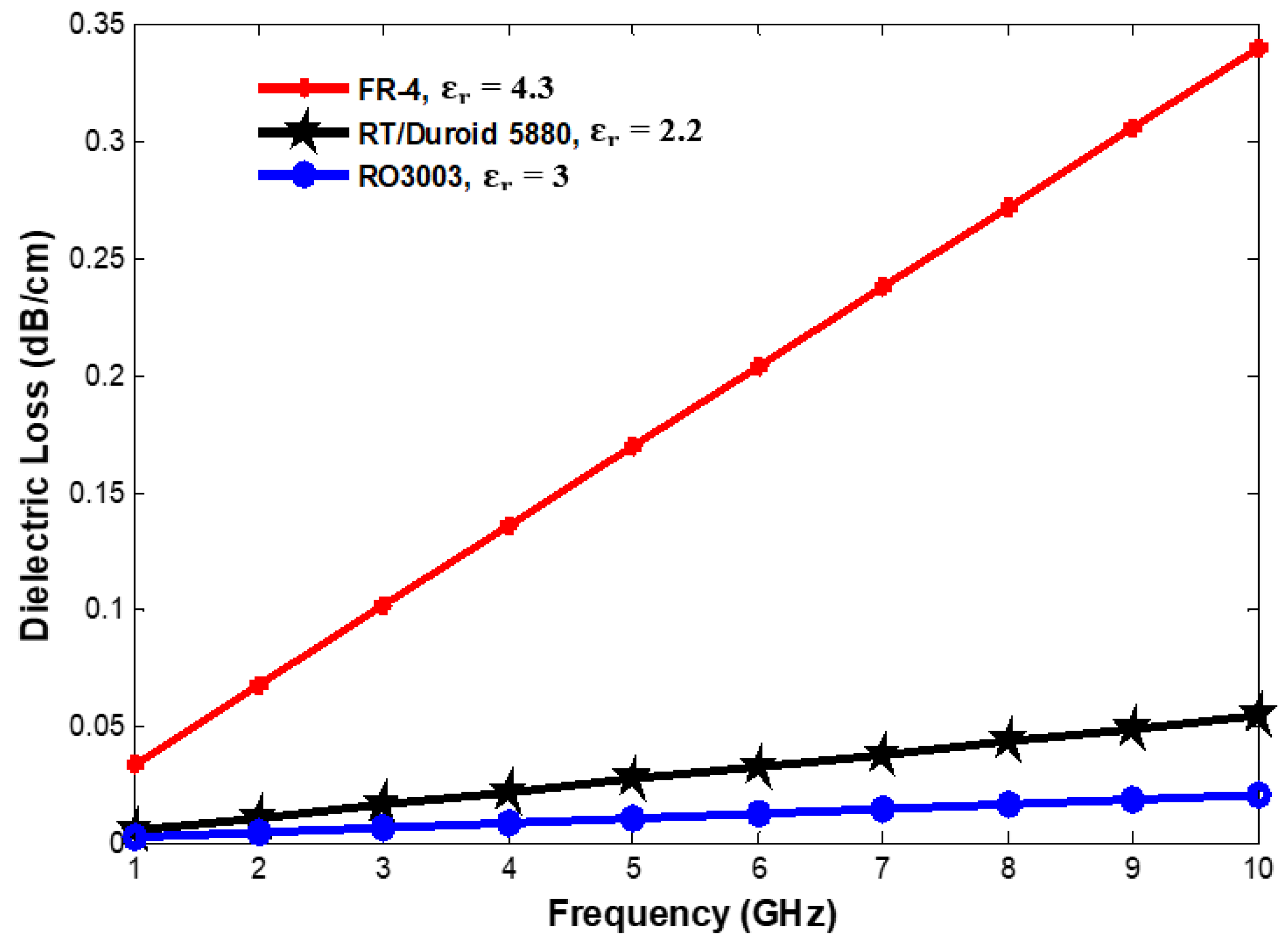
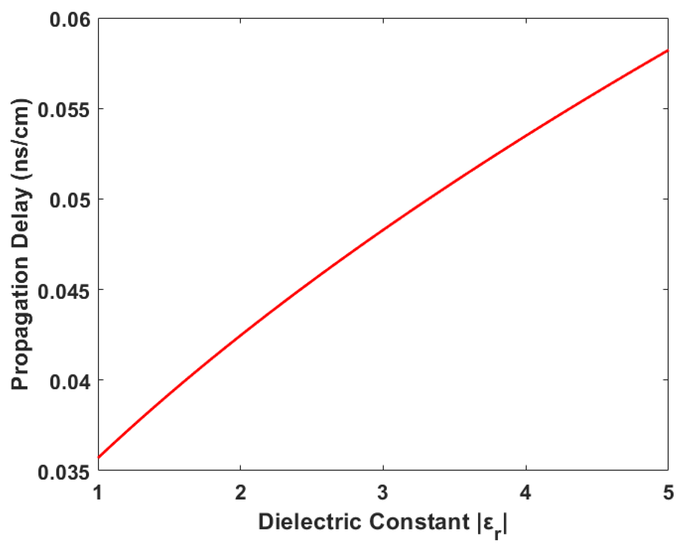
2. Properties of the Dielectric Substrates
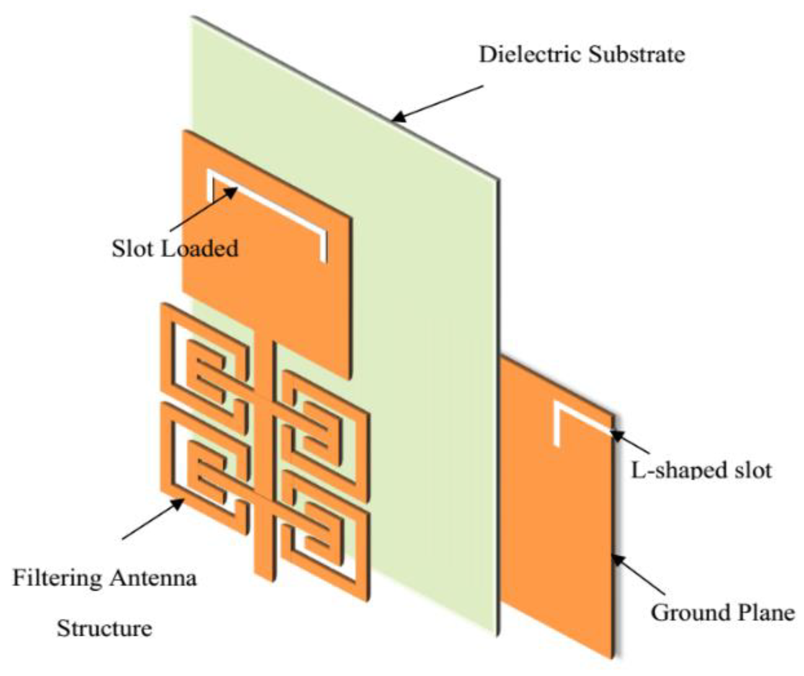
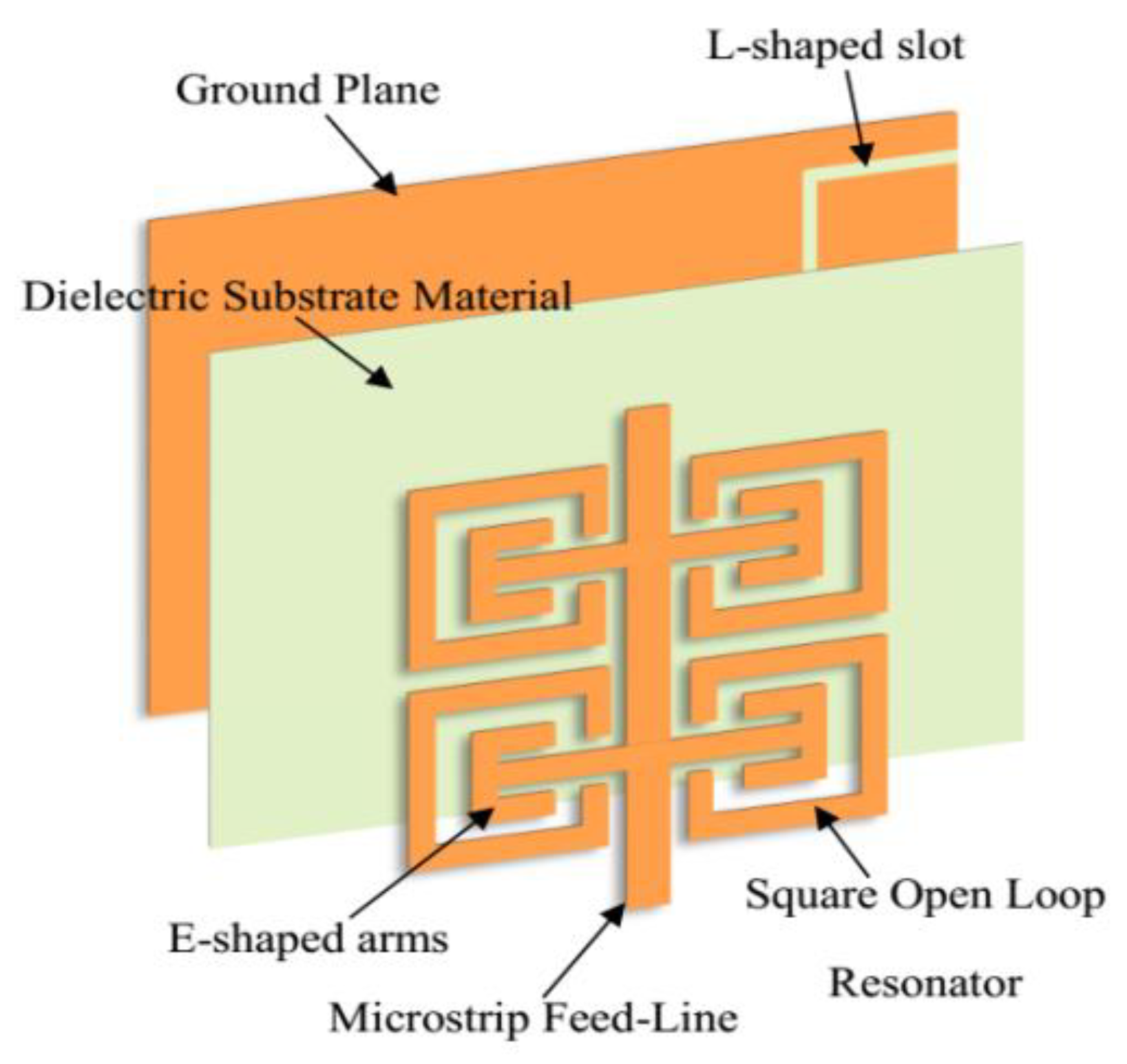
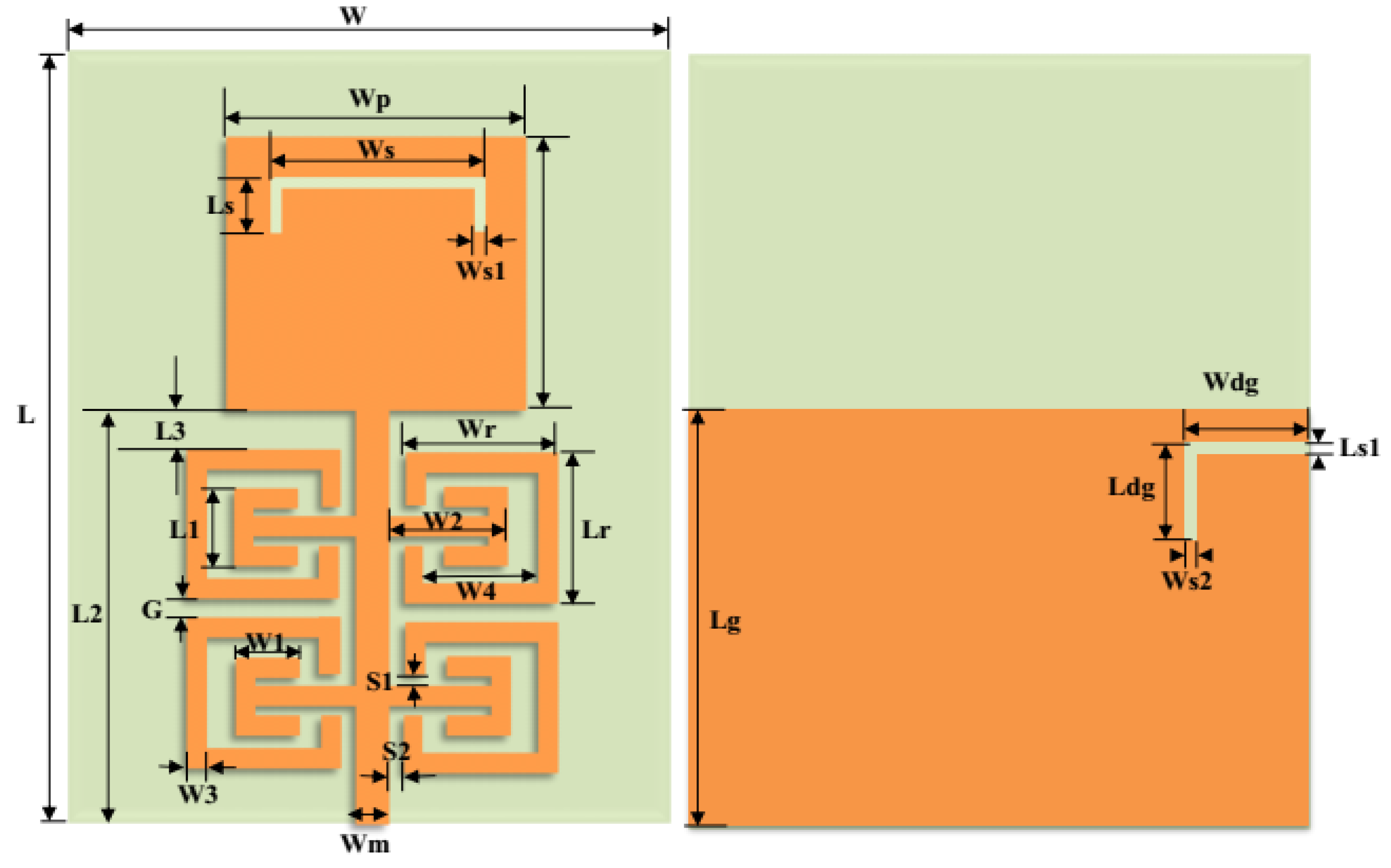
3. Microstrip Filter-Antenna Configuration
4. Simulation and Measurement Results
5. Conclusions
Author Contributions
Funding
Acknowledgments
Conflicts of Interest
References
- Hussaini, A. Green Flexible RF for 5G. In Fundamentals of 5G Mobile Networks, 1st ed.; Rodriguez, J., Ed.; John Wiley and Sons: Hoboken, NJ, USA, 2015. [Google Scholar]
- Rodriguez, J.; Radwan, A.; Barbosa, C.; Fitzek, F.H.P.; Abd-Alhameed, R.A.; Noras, J.M.; Jones, S.M.R.; Politis, I.; Galiotos, P.; Schulte, G.; et al. SECRET—Secure Network Coding for Reduced Energy next Generation Mobile Small Cells: A European Training Network in Wireless Communications and Networking for 5G. In Proceedings of the 2017 Internet Technologies and Applications (ITA), Wrexham, UK, 12–15 September 2017; pp. 329–333. [Google Scholar]
- Parchin, N.O. Microwave/RF Components for 5G Front-End Systems; AVID SCIENCE: Telangana, India, 2020. [Google Scholar]
- Al-Yasir, Y.; Abd-Alhameed, R.A.; Noras, J.M.; Abdulkhaleq, A.M.; Ojaroudi, N. Design of Very Compact Combline Band-Pass Filter for 5G Applications. In Proceedings of the Loughborough Antennas & Propagation Conference (LAPC), Loughborough, UK, 12–13 November 2018; pp. 1–4. [Google Scholar]
- Abdulraheem, Y.I.; Abdullah, A.; Mohammed, H.; Abd-Alhameed, R.; Noras, J. Design of Frequency reconfigurable Multiband Compact Antenna using two PIN diodes for WLAN/WiMAX Applications. IET Microw. Antennas Propag. 2017, 11, 1098–1105. [Google Scholar] [CrossRef] [Green Version]
- Al-Yasir, Y.I.A.; Tu, Y.; Bakr, M.S.; Parchin, N.O.; Asharaa, A.S.; Mshwat, W.A.; Abd-Alhameed, R.A.; Noras, J.M. Design of multi-standard single/tri/quint-wideband asymmetric stepped-impedance resonator filters with adjustable TZs. IET Microw. Antennas Propag. 2019, 13, 1637–1645. [Google Scholar] [CrossRef] [Green Version]
- Liu, H.; Ren, B.P.; Li, S.; Guan, X.H.; Wen, P.; Peng, X.X.Y. High-Temperature Superconducting Bandpass Filter Using Asymmetric Stepped-Impedance Resonators with Wide-Stopband Performance. IEEE Trans. Appl. Supercond. 2015, 25, 1–6. [Google Scholar]
- Al-Yasir, Y.I.A.; Tu, Y.; Parchin, N.O.; Abdulkhaleq, A.; Kosha, J.; Ullah, A.; Abd-Alhameed, R.; Noras, J. New Multi-standard Dual-Wideband and Quad-Wideband Asymmetric Step Impedance Resonator Filters with Wide Stop Band Restriction. Int. J. RF Microw. Comput. Aided Eng. 2019, 29, e21802. [Google Scholar] [CrossRef]
- Al-Yasir, Y.I.A.; Tu, Y.; Parchin, N.O.; Elfergani, I.; Abd-Alhameed, R.; Rodriguez, J.; Noras, J. Mixed-coupling multi-function quint-wideband asymmetric stepped impedance resonator filter. Microw. Opt. Tech. Lett. 2019, 61, 1181–1184. [Google Scholar] [CrossRef]
- Mohammed, H.J.; Abdulsalam, F.; Abdulla, A.S.; Ali, R.S.; Abd-Alhameed, R.A.; Noras, J.M.; Abdulraheem, Y.I.; Ali, A.; Rodriguez, J.; Abdalla, A.M. Evaluation of genetic algorithms, particle swarm optimisation, and firefly algorithms in antenna design. In Proceedings of the 13th International Conference on Synthesis, Modeling, Analysis and Simulation Methods and Applications to Circuit Design (SMACD), Lisbon, Portugal, 27–30 June 2016; pp. 1–4. [Google Scholar]
- Hou, Z.; Liu, C.; Zhang, B.; Song, R.; Wu, Z.; Zhang, J.; He, D. Dual-/Tri-Wideband Bandpass Filter with High Selectivity and Adjustable Passband for 5G Mid-Band Mobile Communications. Electronics 2020, 9, 205. [Google Scholar] [CrossRef] [Green Version]
- Al-Yasir, Y.I.A.; Ojaroudi Parchin, N.; Abdulkhaleq, A.M.; Bakr, M.S.; Abd-Alhameed, R.A. A Survey of Differential-Fed Microstrip Bandpass Filters: Recent Techniques and Challenges. Sensors 2020, 20, 2356. [Google Scholar] [CrossRef] [Green Version]
- Al-Yasir, Y.I.A.; Parchin, N.O.; Abdulkhaleq, A.; Abd-Alhameed, R.; Noras, J. Recent Progress in the Design of 4G/5G Reconfigurable Filters. Electronics 2019, 8, 114. [Google Scholar] [CrossRef] [Green Version]
- Ghouz, H.H.M.; Sree, M.F.A.; Ibrahim, M.A. Novel Wideband Microstrip Monopole Antenna Designs for WiFi/LTE/WiMax Devices. IEEE Access 2020, 8, 9532–9539. [Google Scholar] [CrossRef]
- Lu, J.; Zhang, H.C.; He, P.H.; Zhang, L.P.; Cui, T.J. Design of Miniaturized Antenna Using Corrugated Microstrip. IEEE Trans. Antennas Propag. 2020, 68, 1918–1924. [Google Scholar] [CrossRef]
- Al-Yasir, Y.; Abdullah, A.; Ojaroudi Parchin, N.; Abd-Alhameed, R.; Noras, J. A New Polarization-Reconfigurable Antenna for 5G Applications. Electronics 2018, 7, 293. [Google Scholar] [CrossRef] [Green Version]
- Yasir, I.A.A.; Hasanain, A.H.A.; Baha, A.S.; Parchin, N.O.; Ahmed, M.A.; Abdulkareem, S.A.; Raed, A.A. New Radiation Pattern-Reconfigurable 60-GHz Antenna for 5G Communications. IntechOpen 2019. Available online: https://www.intechopen.com/online-first/new-radiation-pattern-reconfigurable-60-ghz-antenna-for-5g-communications (accessed on 26 September 2019).
- Ogurtsov, S.; Koziel, S. A Conformal Circularly Polarized Series-Fed Microstrip Antenna Array Design. IEEE Trans. Antennas Propag. 2020, 68, 873–881. [Google Scholar] [CrossRef]
- Al-Yasir, Y.I.A.; Parchin, N.O.; Abdulkhaleq, A.; Hameed, K.; Al-Sadoon, M.; Abd-Alhameed, R. Design, Simulation and Implementation of Very Compact Dual-band Microstrip Bandpass Filter for 4G and 5G Applications. In Proceedings of the 16th International Conference on Synthesis, Modeling, Analysis and Simulation Methods and Applications to Circuit Design (SMACD), Lausanne, Switzerland, 15–18 July 2019; pp. 41–44. [Google Scholar]
- Yang, D.; Zhai, H.; Guo, C.; Li, H. A Compact Single-Layer Wideband Microstrip Antenna with Filtering Performance. IEEE Antennas Wirel. Propag. Lett. 2020, 19, 801–805. [Google Scholar] [CrossRef]
- Khan, A.; Nema, R. Analysis of Five Different Dielectric Substrates on Microstrip Patch Antenna. Int. J. Comput. Appl. 2012, 55, 40–47. [Google Scholar] [CrossRef]
- Chuang, C.-T.; Chung, S.-J. A new compact filtering antenna using defected ground resonator. In Proceedings of the Microwave Conference Proceedings (APMC), 2010 Asia-Pacific, Yokohama, Japan, 7–10 December 2010; pp. 1003–1006. [Google Scholar]
- Coonrod, J. Choosing Circuit Materials for Millimeter-Wave Applications. High Freq. Electron. 2013, 3, 22–30. [Google Scholar]
- Cui, J.; Zhang, A.; Yan, S. Co-design of a filtering antenna based on multilayer structure. Int. J. RF Microw. Comput. Aided Eng. 2020, 30, e22096. [Google Scholar] [CrossRef]
- Hua, C.; Liu, M.; Lu, Y. Planar integrated substrate integrated waveguide circularly polarized filtering antenna. Int. J. RF Microw. Comput. Aided Eng. 2019, 29, e21517. [Google Scholar] [CrossRef]
- Al-Yasir, Y.I.A.; Parchin, N.O.; Alabdallah, A.; Abdulkhaleq, A.M.; Abd-Alhameed, R.A.; Noras, J.M. Noras, Design of Bandpass Tunable Filter for Green Flexible RF for 5G. In Proceedings of the 2019 IEEE 2nd 5G World Forum (5GWF), Dresden, Germany, 30 September–2 October 2019. [Google Scholar]
- Niu, B.; Tan, J.-H. Dipole filtering antenna with quasi-elliptic peak gain response using parasitic elements. Microw. Opt. Technol. Lett. 2019, 61, 1612–1616. [Google Scholar] [CrossRef]
- Park, J.; Jeong, M.-J.; Hussain, N.; Rhee, S.; Park, S.; Kim, N. A low-profile high-gain filtering antenna for fifth generation systems based on nonuniform metasurface. Microw. Opt. Technol. Lett. 2019, 61, 2513–2519. [Google Scholar] [CrossRef]
- Al-Yasir, Y.I.A.; Parchin, N.O.; Abd-Alhameed, R.A. A Differential-Fed Dual-Polarized High-Gain Filtering Antenna Based on SIW Technology for 5G Applications. In Proceedings of the 14th European Conference on Antennas and Propagation (EuCAP), Copenhagen, Denmark, 15–20 March 2020; pp. 1–5. [Google Scholar]
- Song, L.; Wu, B.; Xu, M.; Su, T.; Lin, L. Wideband balun filtering quasi-Yagi antenna with high selectivity. Microw. Opt. Technol. Lett. 2019, 61, 2336–2341. [Google Scholar] [CrossRef]
- Wu, W.; Fan, R.; Wang, J.; Zhang, Q. A broadband low profile microstrip filter-antenna with an omni-directional pattern. In Proceedings of the 2014 3rd Asia-Pacific Conference on Antennas and Propagation, Harbin, China, 26–29 July 2014; pp. 580–582. [Google Scholar]
- Lin, C.; Chung, S. A Compact Filtering Microstrip Antenna with Quasi-Elliptic Broadside Antenna Gain Response. IEEE Antennas Wirel. Propag. Lett. 2011, 10, 381–384. [Google Scholar]
- Wu, W.; Ma, B.; Wang, J.; Wang, C. Design of a microstrip antenna with filtering characteristics for wireless communication systems. In Proceedings of the 2017 Sixth Asia-Pacific Conference on Antennas and Propagation (APCAP), Xi’an, China, 16–19 October 2017; pp. 1–3. [Google Scholar]
- Al-Yasir, Y.I.A.; Parchin, N.O.; Abd-Alhameed, R.A. New High-Gain Differential-Fed Dual-Polarized Filtering Microstrip Antenna for 5G Applications. In Proceedings of the 14th European Conference on Antennas and Propagation (EuCAP), Copenhagen, Denmark, 15–20 March 2020; pp. 1–5. [Google Scholar]
- Wu, W.; Yin, Y.; Zuo, S.; Zhang, Z.; Xie, J. A New Compact Filter-Antenna for Modern Wireless Communication Systems. IEEE Antennas Wirel. Propag. Lett. 2011, 10, 1131–1134. [Google Scholar]
- Ohira, M.; Ma, Z. An efficient design method of microstrip filtering antenna suitable for circuit synthesis theory of microwave band-pass filters. In Proceedings of the 2015 International Symposium on Antennas and Propagation (ISAP), Hobart, TAS, Australia, 9–12 November 2015; pp. 1–4. [Google Scholar]
- Al-Yasir, Y.I.A.; Alhamadani, H.A.; Kadhim, A.S.; Ojaroudi Parchin, N.; Saleh, A.L.; Elfergani, I.T.E.; Rodriguez, J.; Abd-Alhameed, R.A. Design of a Wide-Band Microstrip Filtering Antenna with Modified Shaped Slots and SIR Structure. Inventions 2020, 5, 11. [Google Scholar] [CrossRef] [Green Version]
- Leys, D. Best materials for 3–6 GHz design. Print. Circuit Des. Manuf. 2004, 34–39. [Google Scholar]
- Khare, A.; Nema, R.; Gour, P.; Thakur, R.K. New multiband E-shape microstrip patch antenna on RT DUROID 5880 substrate and RO4003 substrate for pervasive wireless communication. Int. J. Comput. Appl. 2010, 975, 8887. [Google Scholar] [CrossRef]
- Afrin, S.S.; Dev, P.R. Performance Analysis of Microstrip Patch Antenna for Ultra Wide Band Application; East West University: Dhaka, Bangladesh, 2015. [Google Scholar]
- Szostak, F.K.; Słobodzian, P. Broadband Dielectric Measurement of PCB and Substrate Materials by Means of a Microstrip Line of Adjustable Width. IEEE Microw. Wirel. Compon. Lett. 2018, 1, 945–947. [Google Scholar] [CrossRef]
- Kapusuz, K.; Lemey, S.; Rogier, H. Substrate-Independent Microwave Components in Substrate Integrated Waveguide Technology for High-Performance Smart Surfaces. IEEE Trans. Microw. Theory Tech. 2018, 1, 3036–3047. [Google Scholar] [CrossRef] [Green Version]
- Breed, G. An introduction to defected ground structures in microstrip circuits. High Frequency Electron. 2008, 7, 50–54. [Google Scholar]
- Mahmud, F.S.; Razalli, M.S.; Rahim, H.A.; Hoon, W.F.; Ilyas, M.Z. Parametric studies on effects of defected ground structure (DGS) for dual band bandstop microstrip filter. EPJ Web Conf. 2017, 1, 1–5. [Google Scholar] [CrossRef] [Green Version]


| Parameter | W | Wp | Ws | Ws1 | Ws2 | Wm | Wr | Wdg | W1 | W2 | W3 | W4 | W5 |
|---|---|---|---|---|---|---|---|---|---|---|---|---|---|
| Dimensions | 42 | 20 | 15 | 0.5 | 0.5 | 2.4 | 10 | 7.5 | 3.9 | 6.6 | 1 | 8 | 2.5 |
| Parameter | L | Lg | Lr | Ls1 | Ls1 | L1 | L2 | L3 | Lp | Ldg | S1 | S2 | G |
| Dimensions | 45 | 25.4 | 9 | 0.4 | 3.5 | 4 | 26 | 3 | 18 | 5.4 | 0.5 | 0.8 | 1 |
| Parameters | Dielectric Substrate Type | ||
|---|---|---|---|
| RT/5880 | RO3003 | FR-4 | |
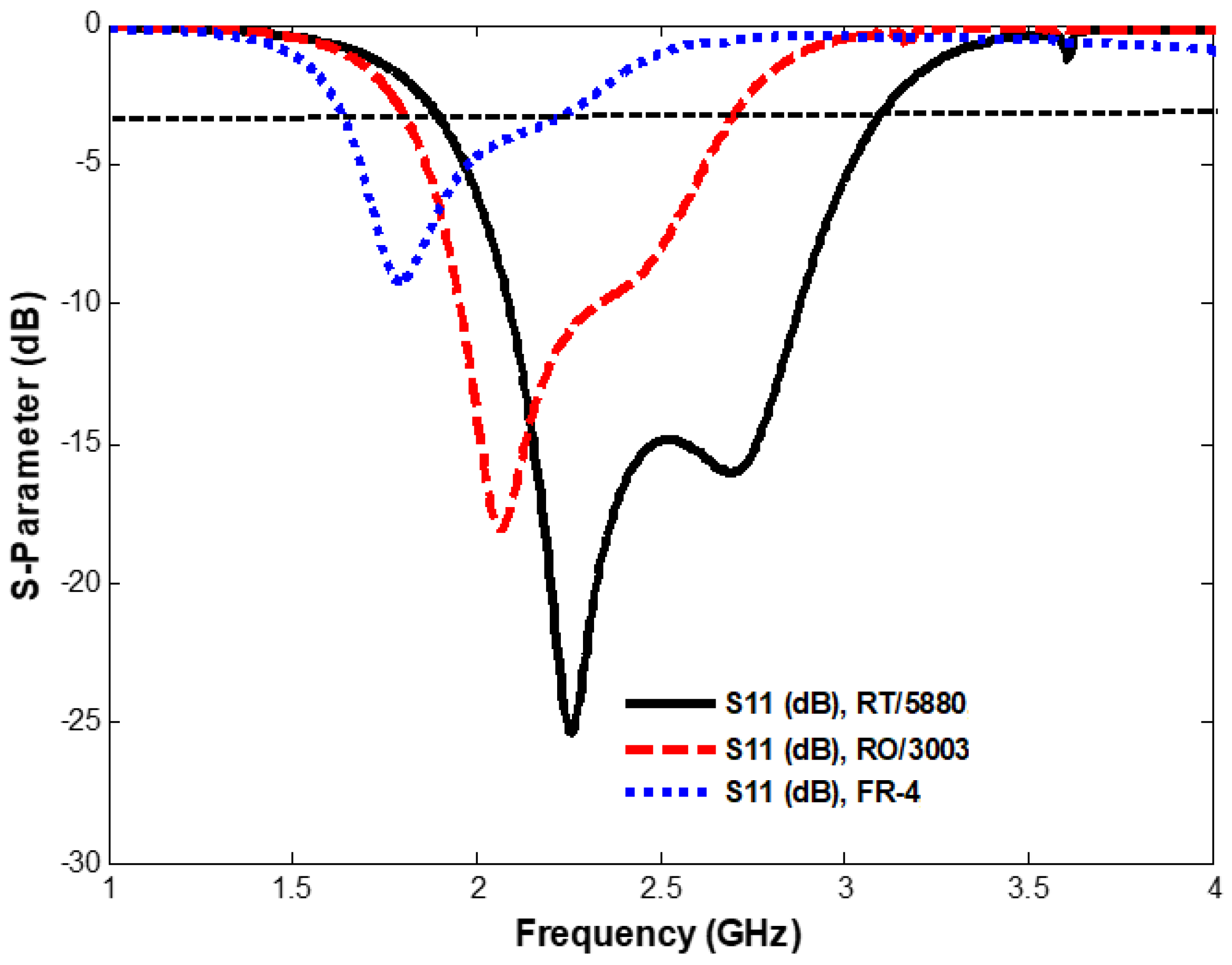
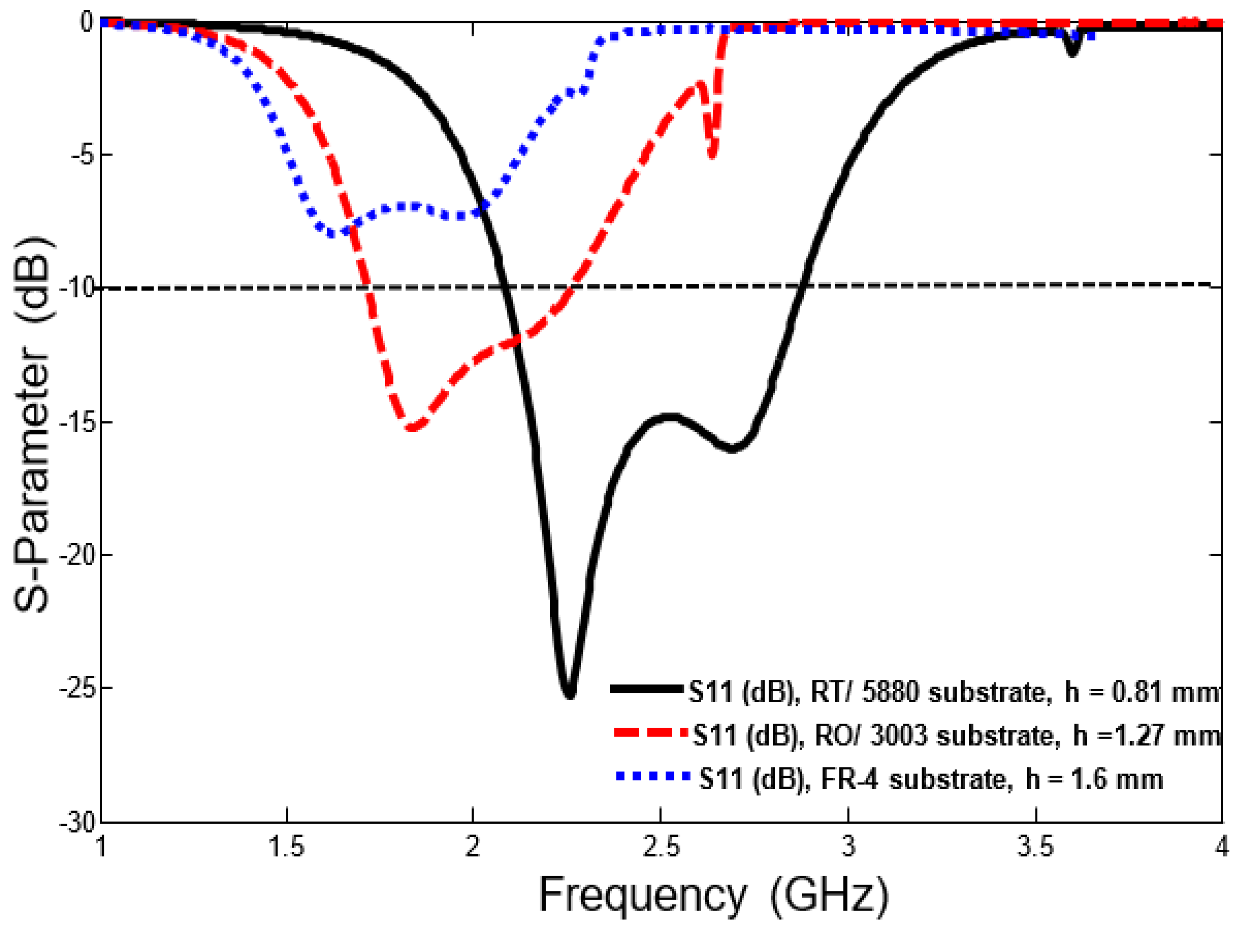
| Centre frequency (f0 GHz) | 2.412 | 2.202 | 1.924 |
| Return loss (dB) | 15 | 12.065 | 6.0314 |
| Maximum Gain (dB) | 4.03 | 2.43 | 1.18 |
| BW (GHz) | 1.22 | 0.922 | 0.657 |
| VSWR | 1.1937 | 1.58 | 2.2 |
| Parameters | Dielectric Substrate Properties | ||
|---|---|---|---|
| RT/5880 (h = 0.81 mm) | RO3003 (h = 1.27 mm) | FR-4 (h = 0.81 mm) | |
| Centre frequency (GHz) | 2.412 | 2.3 | 2.049 |
| Return loss (dB) | 15 | 13.063 | 7.04 |
| Maximum Gain (dB) | 4.1 | 2.63 | 2.22 |
| BW (GHz) | 1.22 | 1.3 | 1.059 |
| VSWR | 1.1937 | 1.52 | 2.24 |
| Ref. | Centre Frequency (GHz) | Fractional Bandwidth (%) | Size (λ0 × λ0) | RL (dB) | Gain (dB) | Extra Structure |
|---|---|---|---|---|---|---|
| [24] | 2.6 | 2.6 | 0.31 × 0.27 | >13 | 2.2 | Multilayer |
| [25] | 11.65 | 4 | 2 × 1.1 | >14 | 5.6 | SIW * |
| [27] | 1.85 | 5.4 | 0.74 × 0.74 | >12 | 6.2 | Multilayer |
| [28] | 3.6 | 15 | 0.92 × 0.86 | >14 | 10 | Metasurface |
| [30] | 2.5 | 22.8 | 1.7 × 1.3 | >20 | 5 | balun |
| [31] | 2.5 | 15 | 0.76 × 0.76 | >15 | 2 | Multilayer |
| [32] | 5 | 2 | 0.37 × 0.32 | >15 | 4 | None |
| [33] | 2.45 | 6.4 | 0.72 × 0.70 | >15 | 6 | None |
| [35] | 2.5 | 16.3 | 0.3 × 0.25 | >20 | 2.4 | None |
| [36] | 2.5 | 8 | 0.45 × 0.45 | >14 | 4.5 | None |
| Prop. | 2.4 | 50 | 0.32 × 0.30 | >16 | 4.9 | None |
© 2020 by the authors. Licensee MDPI, Basel, Switzerland. This article is an open access article distributed under the terms and conditions of the Creative Commons Attribution (CC BY) license (http://creativecommons.org/licenses/by/4.0/).
Share and Cite
Al-Yasir, Y.I.A.; Alkhafaji, M.K.; A. Alhamadani, H.; Ojaroudi Parchin, N.; Elfergani, I.; Saleh, A.L.; Rodriguez, J.; Abd-Alhameed, R.A. A New and Compact Wide-Band Microstrip Filter-Antenna Design for 2.4 GHz ISM Band and 4G Applications. Electronics 2020, 9, 1084. https://doi.org/10.3390/electronics9071084
Al-Yasir YIA, Alkhafaji MK, A. Alhamadani H, Ojaroudi Parchin N, Elfergani I, Saleh AL, Rodriguez J, Abd-Alhameed RA. A New and Compact Wide-Band Microstrip Filter-Antenna Design for 2.4 GHz ISM Band and 4G Applications. Electronics. 2020; 9(7):1084. https://doi.org/10.3390/electronics9071084
Chicago/Turabian StyleAl-Yasir, Yasir I. A., Mohammed K. Alkhafaji, Hana’a A. Alhamadani, Naser Ojaroudi Parchin, Issa Elfergani, Ameer L. Saleh, Jonathan Rodriguez, and Raed A. Abd-Alhameed. 2020. "A New and Compact Wide-Band Microstrip Filter-Antenna Design for 2.4 GHz ISM Band and 4G Applications" Electronics 9, no. 7: 1084. https://doi.org/10.3390/electronics9071084