Article

Mobility Management Based on Beam-Level Measurement Report in 5G Massive MIMO Cellular Networks

1
Department of Electronic Engineering, Sogang University, Seoul 04107, Korea
2
Department of Electrical Engineering and Computer Science, University of Michigan, Ann Arbor, MI 48109, USA
*
Author to whom correspondence should be addressed.
Electronics 2020, 9(5), 865; https://doi.org/10.3390/electronics9050865
Submission received: 28 April 2020 / Revised: 20 May 2020 / Accepted: 21 May 2020 / Published: 23 May 2020
(This article belongs to the Section Microwave and Wireless Communications)

Abstract

:
Massive multiple-input-multiple-output (MMIMO) in the mmWave band is an essential technique to achieve the desired performance for 5G new radio (NR) systems. To employ mmWave MMIMO technology, an important challenge is maintaining seamless mobility to users because we need to consider beam-switching within a cell besides the handover between cells. For mobility management in 5G NR systems, 3GPP specified a beam-level-mobility scheme that includes beam pairing and maintenance between a transmitter (Tx) and receiver (Rx) pair. We propose a unific-measurement report based mobility management scheme for improved radio-link-failure (RLF) rate and the accuracy of the Tx-Rx-beam-pair (TRP) selection with low overhead in 5G mmWave MMIMO networks where both handover and beam-switching are required. Furthermore, we modeled a finite-state-machine (FSM) for a user terminal to evaluate performance gain based on a system-level-simulation (SLS). We use the FSM-based Monte-Carlo SLS for the experiment and compare the performance of the proposed scheme with that of existing schemes in the scenario where both beam and cell-level-mobility are necessary. We show that the proposed scheme achieves an improvement in terms of the 3-dB loss probabilities representing the accuracy of the TRP selection, signal-to-interference-and-noise-ratio (SINR), and RLF rates with a lower signaling overhead compared to existing methods.

1. Introduction

Fifth-generation (5G) new radio (NR)—the first stage of the 5G systems—has led to various user-experience services, shorter latency, and higher user data traffic compared to the previous generation mobile communication systems such as LTE/LTE-A. These remarkable successes have been enabled by various techniques such as massive multiple-input-multiple-output (MIMO) systems and network slicing in various communication layer technologies [1,2]. For the application of massive MIMO, employing an extremely high-frequency band is a highly effective technique in 5G NR to facilitate a significantly reduced antenna size and mitigated interferences due to significant propagation-pass-loss [3,4]. To shape several beams using a massive number of antenna elements such as a uniform-linear-array (ULA) in the mmWave environment, a useful technique is mapping the one-logical port based on several antennas to a one-synchronization-symbol-burst (SSB) beam [5]. To exploit multi-beam-based architecture with narrow beam coverage in massive MIMO networks, we need to investigate beam switching (BS) schemes that have not been seriously investigated previously.

1.1. Mobility Management Framework in 5G NR

In the next-generation-Node-B (gNB) of multi-beam architecture, there is a significantly increased number of measurements for network management including handover or beam switching. Multiple-beam architecture leads to independently small coverage with respect to each beam. Therefore, supporting seamless user-mobility based on multiple-beam operation scenarios is an important issue in massive MIMO networks [6,7]. At the initial stage of 5G technologies, the research was focused to improve handover performance [8,9,10,11,12,13,14]. In the multi-beams architecture, mobility management has been defined based on “cell-level mobility” and “beam-level mobility” after release 15 [15]. Cell-level mobility is the handover process where the user establishes a new connection to a new cell for better quality-of-service (QoS). Beam-level mobility is the procedure in which the user establishes a new data-path to a new beam within the same cell coverage.

1.2. Beam Management Technique Framework for 5G Mobility Management

Multiple-beam within a cell need to be carefully managed to maintain high-quality data communications and seamless intra-cell mobility [16]. There are various schemes for supporting beam management, e.g., beam sweeping, beam measurement, beam reporting, beam determination, beam maintenance, and beam failure recovery [17,18]. To improve mobility performance in beam management, various techniques have been proposed [17,18,19,20,21,22,23,24,25,26]. The framework of beam management and the antenna structure are summarized in [17]. Reference [19] focuses on beam management at the initial access (IA) stage. Reference [20] summarizes the existing techniques for beam-switching methods in IA, where a new searching method to detect a beam to reduce outage probability and power consumption was proposed. Reference [21] shows experimental throughput results under indoor scenarios with a beam channel environment. Reference [22] proposes a new physical channel model to report beam measurement. Reference [23,24] focuses on a beam tracking method for supporting beam-level mobility. Reference [18] described the spectral efficiency result in a single-cell and the multiple-beam environment with three different beam reporting schemes. Reference [25] proposed a simplified downlink command for beam-mobility, and a measurement report for a beam refinement scheme was also reported. Furthermore, [26] investigated a beam-selection method to enhance the throughput; however, a realistic mobility procedure was not considered. Although these studies propose effective beam reporting and beam switching schemes for mobility enhancement in a multi-beams environment, further research is necessary for practical implementation such as ultra-dense-networks (UDN) of a typical 5G environment. Especially because [18,25] described two main categories in terms of beam reporting methods, the mobility performance of further research needs to be compared to that of these two main categories. Both beam-level mobility and cell-level mobility occur in practical mobile communication systems; therefore, the performance evaluation of mobility management in the practical environment of 5G networks is required [27,28].

1.3. Contribution

In this paper, we proposed a unific-measurement-report (MR) scheme based 5G mobility management for both beam-level mobility and cell-level mobility. Based on a unific MR, both serving and adjacent cells are involved in intra/inter-cell beam management. In addition, we model a novel finite-state-machine (FSM) for 5G users, which is extended from the user state machine of conventional LTE/LTE-A networks [28]. With this FSM model, we can evaluate performance metrics via Monte Carlo system-level-simulation (SLS) to reflect a practical 5G NR system. We compare our work to previous works such as [18,25] in terms of performance metrics such as downlink/uplink overhead, 3-dB loss probability, and RLF rates. That is, we compare the mobility performance of our proposed scheme to that of the existing two main beam-reporting schemes in the practical 5G environments. We show that the proposed scheme outperforms previous works in terms of mobility performance such as system overhead, the accuracy of transmitter (Tx) and receiver (Rx) beam-pair (TRP) selection, and radio-link-failure (RLF) rates. The rest of this paper is organized as follows: the system model is described in Section 2. In Section 3, we describe our unific MR-based mobility algorithm. Our improved FSM is proposed in Section 4. The numerical results are shown in Section 5. The conclusions of this work are provided in Section 6.

2. System Model

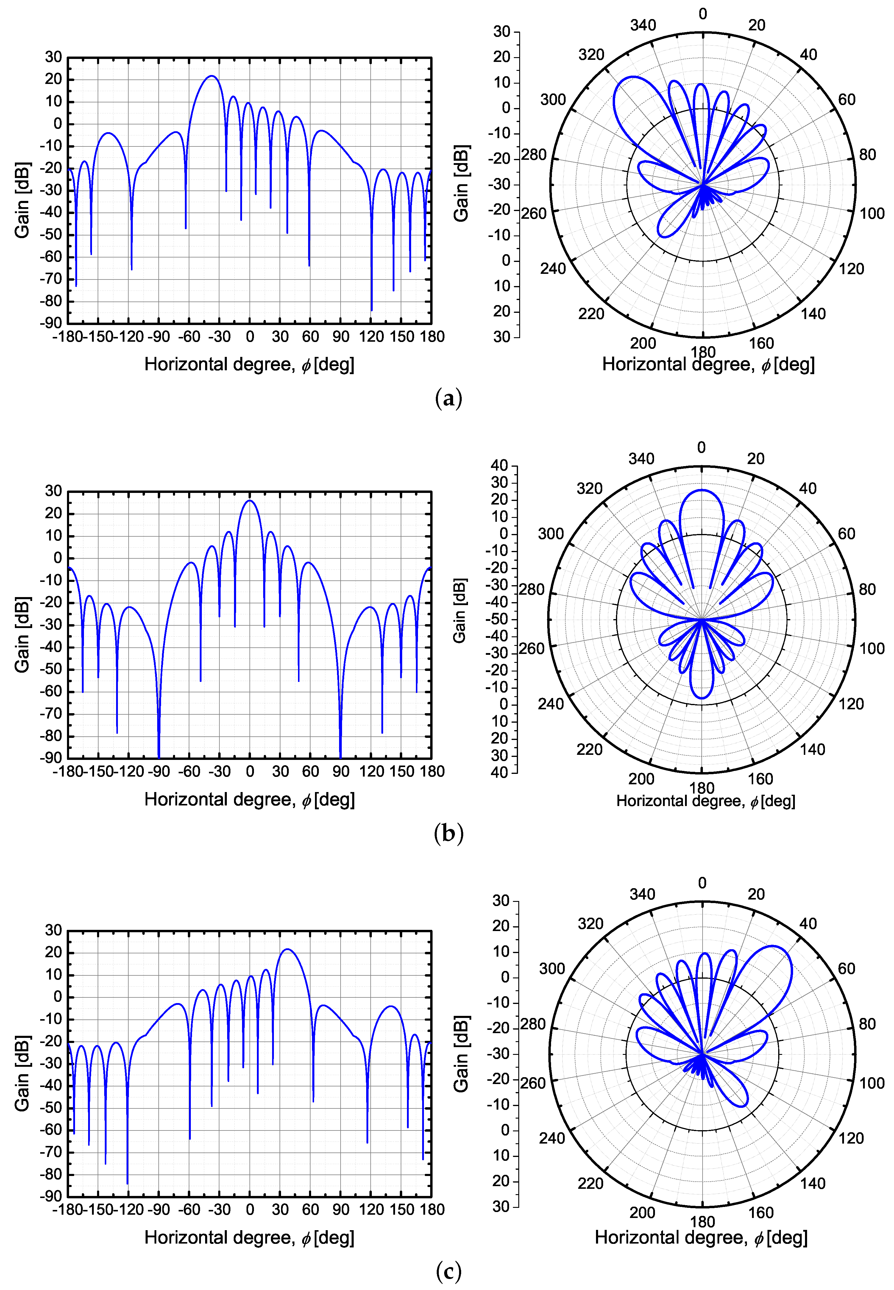
2.1. Beam Shaping Model for Massive MIMO Networks

We describe how to design a beam with the ULA antenna based on the active antenna array system (AAS) as shown in [29,30]. We describe an antenna array radiation pattern, and explain the beam pattern based on the obtained antenna array radiation pattern. The antenna array radiation pattern, A A ( · ) is a combination of the element radiation pattern, A E ( · ) and the array factor, A F ( · ) . We define the antenna array radiation pattern A A ( · ) with a vertical and horizontal angle pair ( θ , ϕ ) as
A A ( θ s , ϕ s , θ , ϕ ) = A E ( θ , ϕ ) + A F ( θ s , ϕ s , θ , ϕ ) ,
where θ s , ϕ s are the vertical and horizontal angle pair of main-beam lobes, respectively. A E ( · ) is an element radiation pattern and A F ( · ) is an array factor with n × n elements.

2.1.1. Element Radiation Pattern

The element radiation pattern A E ( · ) is described as
A E ( θ , ϕ ) = G E , max min [ { A E , V ( θ ) + A E , H ( ϕ ) } , A m ] ,
where G E , max = 8 dBi is the maximum directional gain of antenna elements. A E , V ( · ) and A E , H ( · ) are vertical and horizontal element patterns, respectively. Furthermore, A m = 30 dB is a front-back ratio. In particular, the vertical element pattern is obtained as
A E , V ( θ ) = min 12 θ 90 θ 3 dB 2 , S L A v ,
where θ 3 dB = 65 is the vertical 3 dB beamwidth, and S L A v = 30 dB is the side-lobe level limit. In addition, the horizontal element pattern is obtained as
A E , H ( ϕ ) = min 12 ϕ 90 ϕ 3 dB 2 , A m ,
where ϕ 3 dB = 65 is the horizontal 3 dB beamwidth.

2.1.2. Array Factor for Antenna Array Radiation Pattern

The array factor A F ( · ) can be described as
A F ( θ s , ϕ s , θ , ϕ ) = 10 log 10 1 + ρ · p = 1 N H r = 1 N V a · w p , r · v p , r 2 1 ,
where N H and N V are the number of antenna elements in the horizontal and vertical directions, respectively. Because we consider the practical ULA, we assume eight for both N H and N V . The parameter, ρ is a correlation level and it is assumed to be unity. a equals 1 / N H N V , which is a constant amplitude because we assume an equal and fixed amplitude for all antenna elements. p and r are indices of the antenna elements in both directions. Then, we describe the beamforming components w p , r and v p , r as
w p , r = e j 2 π ( r 1 ) d V λ cos θ s + ( p 1 ) d H λ sin θ s sin ϕ s , v p , r = e j 2 π ( r 1 ) d V λ cos θ + ( p 1 ) d H λ sin θ sin ϕ ,
where λ is a wavelength of the employed band frequency, d V and d H are spacing distances between the vertical and horizontal elements of the antenna array, respectively. In our system model, we assume evenly spaced two-dimensional plane antenna. Therefore, both d V and d H are λ / 2 .

2.1.3. Beam Pattern Model Based on Antenna Array Radiation Pattern

We consider the S sectors (i.e., cells) in a single gNB. Furthermore, each sector activates at least 1 horizontal main beams from the set of main beam candidates, L = { 0 , , L 1 } . To guarantee the equal angular distance of each main-beam, we defined the horizontal main-beam factor as follows:
G t ( l ) = τ A A ( θ s , ϕ s , θ , ϕ ) , ϕ s = 360 S ( l L 1 ) , l L ,
where l is a beam-index in the sector, L is the maximum number of the beam candidates, and τ is an on–off factor. In addition, θ s and θ are 90 because we consider the environment that vertical angle is always 90 . We represent the beam pattern of each beam-index in case of S = 3 and L = 3 . i.e., ϕ s = 40 , 0 , 40 cases as shown in Figure 1. We can confirm that the degree of the main beam is the same as the degree where we obtain the maximum-gain points.

2.2. Channel Model

To describe the channel model, we clarify the deployment of the cells and their attachment to the users. We consider 5G massive MIMO networks with K small cells. The sets of cells are denoted by K = { 1 , , K } . There are I users in the system, including I s stationary users and I m = I I s moving users, which are denoted by I m = { 1 , , I m } and I s = { I m + 1 , , I } , respectively. Let I = I m I s = { 1 , , I } define the set of all users. Furthermore, we consider the scenario where only 1-standing users are associated with the only 1-cell to activate at least an 1 beam of all cells.

2.2.1. SINR Definitions

We can define the downlink signal-to-interference-and-noise-ratio (SINR) at i-th user from all cells as
γ ( i ) = p ( k s ) g t ( l s ) h ( k s , i ) n ( i ) + k k s K L p ( k ) g t ( l ) h ( k , i ) + l l s L p ( k s ) g t ( l ) h ( k s , i ) , k K , l L , i I ,
where k s and l s are the indices of the serving cell and the serving-beam for the i-th user, respectively, and g t ( · ) is the linear scale value of G t ( · ) . p ( k ) is the Tx power of the cell. Furthermore, h ( k , i ) is a distance-based channel gain between the k-th cell and i-th user. We consider pathloss, shadow fading, small-scale fading, and the user received antenna gain for calculating h ( k , i ) .

2.2.2. Probabilistic Path Loss Model

We consider massive MIMO networks with the mmWave band, and therefore we used a realistic 28 GHz channel assessment described in [31,32,33,34,35,36,37,38,39]. The mmWave frequencies are much sensitive to any line-of-sight (LOS) or non-LOS (NLOS) condition that exists in the channel link. Furthermore, there is a possibility that there is no available link between Tx and Rx, and such a channel link is said to be in outage. We can use the probability function to find a channel condition as shown below [31,32]:
p OUT ( d ) = max 0 , 1 e a out d + b out ,
p LOS ( d ) = 1 p out ( d ) e a LOS d ,
p NLOS ( d ) = 1 p out ( d ) p LOS ( d ) ,
where a out , b out , and a LOS are outage and LOS coefficients, respectively, and the values are obtained by measured data in [31]. With this probabilistic model, we define the distance pathloss model based on an alpha-beta-gamma model as [31,37]:
L LOS ( d ) = α LOS + 10 β LOS log 10 ( d ) + ξ LOS ,
L NLOS ( d ) = α NLOS + 10 β NLOS log 10 ( d ) + ξ NLOS ,
where L LOS ( d ) , L NLOS ( d ) are dB scale values in relation to d in meters. Furthermore, α LOS , α NLOS , β LOS , and β NLOS represent measured data in [31]. ξ LOS and ξ NLOS are shadow-fading variables.

2.2.3. Fading Model

We use a shadow-fading model based on the 28-GHz fading measurement data [32]. The distribution of shadow-fading follows a log-normal distribution. Furthermore, the standard deviation of the shadow-fading is different in the LOS and NLOS cases [32]. This can be represented as
ξ LOS N ( 0 , σ LOS 2 ) ,
ξ NLOS N ( 0 , σ NLOS 2 ) ,
where standard deviations σ LOS and σ NLOS are expressed in decibel units. Next, we define small-scale fading. From the measured data in [33], we can use the Rayleigh-fading model for each link.

2.3. Performance Metric

In this section, we describe the performance metric to evaluate the performance of the proposed scheme compared to previous works. The first component of the performance metric is overhead performance, which consists of downlink and uplink aspects. There are two kinds of uplink reporting messages. The first one is the “periodic channel state information reference signal (CSI-RS) report” reporting the reference-signal-received-power (RSRP) information and beam ID periodically [18]. The second one is the MR, reporting RSRP and beam or cell ID which satisfies the measurement event condition. It is used in the proposed scheme, and in [25]. Therefore, the uplink overhead can be calculated from the message size of “periodic CSI-RS report” in the physical-uplink-control-channel (PUCCH) and MR in the physical-uplink-shared-channel (PUSCH). The size of the single periodic CSI-RS report message, M CSI - RS , can be calculated as [40]
M CSI - RS = log 2 K s SSB + log 2 K s CSI - RS + M RSRP ,
where K s SSB , K s CSI - RS are the number of the SSB and CSI-RS beams, respectively. M RSRP is the bits for representing RSRP, which usually comprises 7-bits. Furthermore, the size of a single MR containing the information of the SSB measurement result M MR can be calculated as [16,25]
M MR = M default + N SSB M RSRP + log 2 K s SSB ,
where M default is a default size of the MR message and N SSB is the number of reported beams. In addition, each single message size of downlink beam-switching and handover command are defined as M BS and M HO , respectively. Next, RLF rates, beam switching failure (BSF) rates, and the handover failure (HOF) rates can be calculated from the number of RLF, too-early handover, too-late handover, too-late beam switching, and early beam-switching versus the number of attempted handover (HO) and beam switching (BS). The other performance metric is a 3-dB loss probability representing the accuracy of beam-pair selection. The 3-dB loss probability is represented as [41]
P 3 dB = P ζ > 2 ,
where ζ is the definition of the power loss, i.e., the ratio of the RSRP value between the selected beam pair s and best beam pair among the m-possible beam pair set B . It can be represented as
ζ = max m B RSRP m RSRP s .
Table 1 lists the description of symbols used in this section.

3. Unific-Measurement-Based Beam Switching and Handover Scheme

In this section, we propose a unific-measurement-based beam switching and handover scheme that improve the mobility performance in mmWave massive MIMO networks. First, we define a new measurement event that leads to a trigger for both beam switching and handover. Next, we introduce the entire procedure of beam switching and handover that can be operated based on 3GPP specifications.

3.1. Proposed Measurement Event for Beam Switching and Handover

We assume that all cells in the system use the same carrier frequency and the same system bandwidth. In addition, we assume that the hysteresis or frequency offset related parameters are set as zero for the serving cell. Then, we define “event A3 entering state” at the i-th user as
p ( k ) g t ( l ) h ( k , i ) + O c n ( k , l , l s ) > p ( k s ) g t ( l s ) h ( k s , i ) + O f f ( l s ) , k K , l L , i I ,
where O c n ( k , l , l s ) is the “beam individual offset” that indicates the specific offset value for the l-th neighbor beam of the k-th cell in the serving beam l s of the serving cell k s . O f f ( l s ) is the “A3-offset” that indicates the value for all neighboring beams in the serving beam. p ( k ) g t ( l ) h ( k , i ) and p ( k s ) g t ( l s ) h ( k s , i ) are RSRP from the l-th neighbor beam in the serving beam l s measured at the i-th user, as specified in Equation (8). After event A3 entering state is triggered, we can determine whether the entering state is a HO or BS.

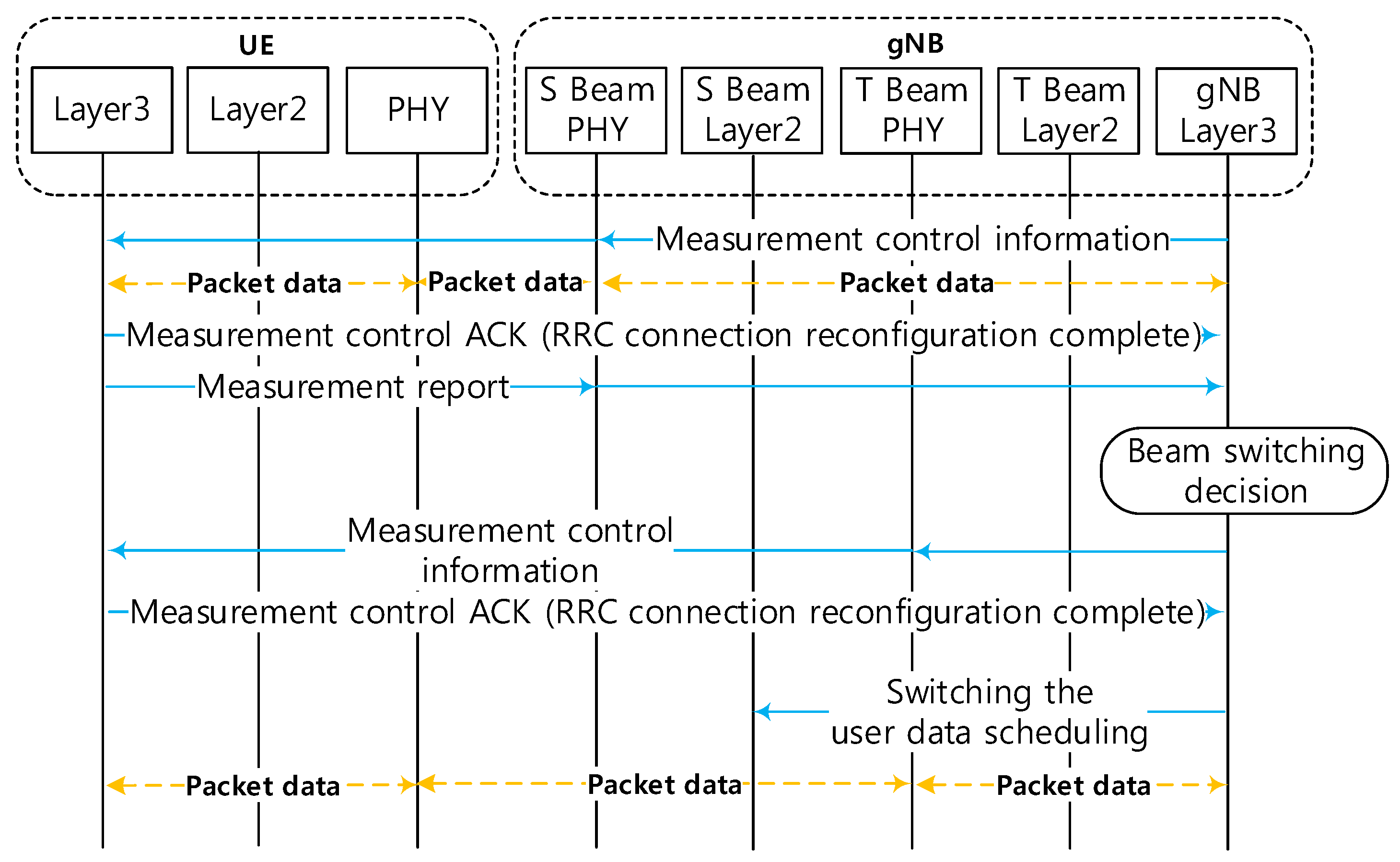
3.2. Proposed Beam Switching and Handover Procedure

As described in the 3GPP specification, each beam in a single-gNB can have its own mobility parameters. However, each value has to be set by the same configuration of the layer-3 (network layer) including the radio-resource-control (RRC) sub-layer. Thus, the beam switching in the same cell is performed in a simpler manner than the handover procedure as shown in Figure 2. There is only one process that needs to be updated by a new control information: “target beam sends new measurement control information.” Therefore, the overall switching process is much shorter than that of the handover process. For conventional handover, the measurement control information includes parameters such as O c n ( k , l , l s ) , O f f ( k s ) , and time-to-trigger (TTT). Concerning the beam-switching, the serving beam also sets the measurement control information for a user. After the parameters are set, the user can measure the signals from the neighbor cells and beams. If the user recognizes the event A3 entering state between two beams, it measures the time of the met-condition of the event for a TTT parameter. If TTT expires, the user sends an MR for a BS or HO. After the serving cell receives an MR, BS, or HO is started based on the following condition:
k K , k k s , l L ,
k = k s , l l s , l L ,
where (21) implies that the target beam (l) is from a cell (k) is different from the serving cell, k s . Equation (22) implies that the target beam (l) is not the serving beam ( l s ) but is from the same serving cell, k s . The serving cell initiates a handover procedure when the condition (21) is satisfied while a beam switching is initiated when condition (22) is satisfied. The beam switching process is shown in Figure 2. The handover process is the same as shown in the 3GPP specification [42].

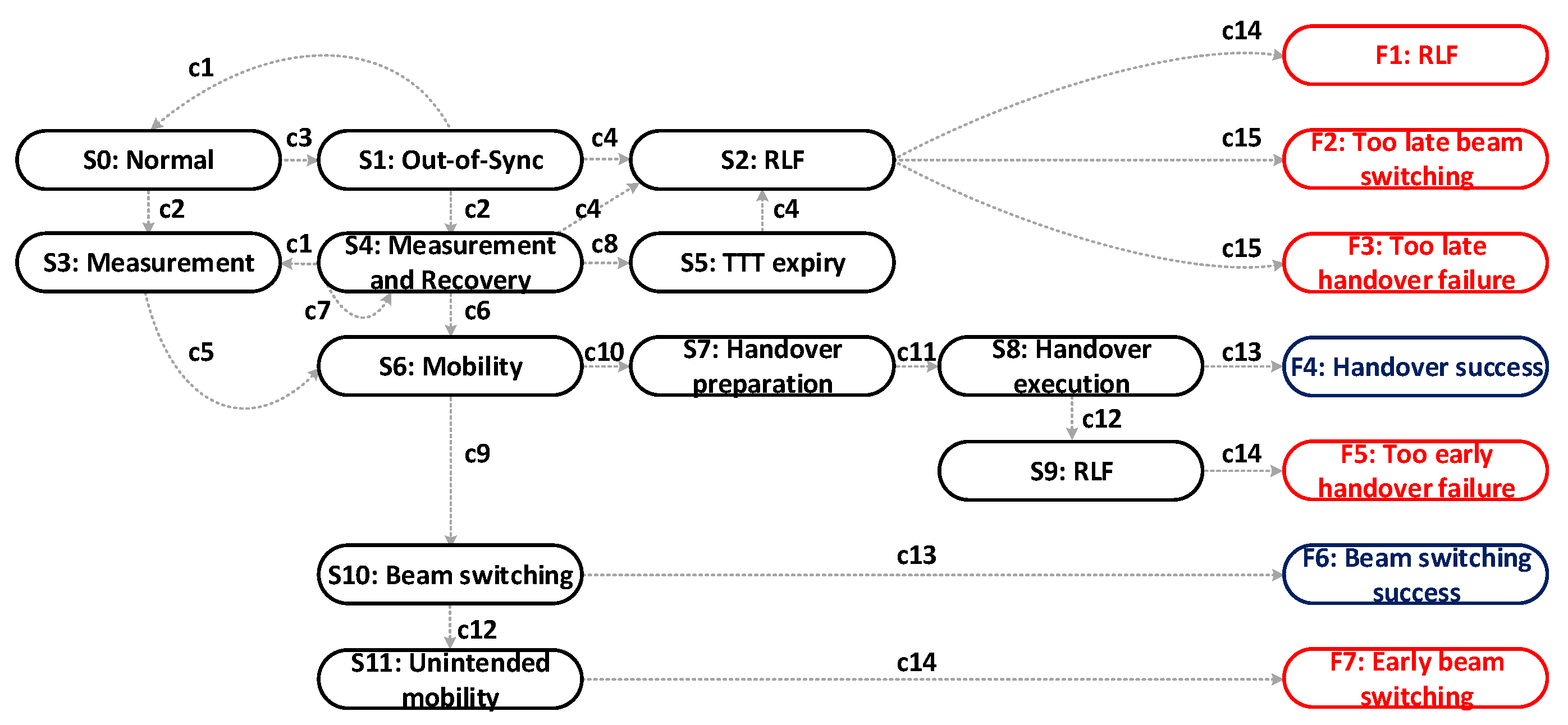
4. User Finite State Machine for Proposed Scheme

In this section, we describe the novel user finite state machine (FSM) that operates with beam switching and handover. It is obtained using the FSM mathematical model as
FSM = ( C , S , S 0 , δ , F ) ,
where C = { c 1 , c 2 , , c 15 } is a set that represents state transition rules. S = { S 0 , S 1 , , S 11 , F 1 , F 2 , , F 7 } is a set of states S and final states F, and S 0 is an initial state of the FSM model. In addition, δ is a state transition that can be shown as δ : S × C S , and F = { F 1 , F 2 , , F 7 } is a set of final states F, which is a subset of S . A diagram of the novel user FSM model is shown in Figure 3.

4.1. State Transition Rules

In this FSM model, we describe state transition rules to explain the scenario of state machines. The i-th user follows the state transition rules at every subframe (1 ms).
State transition rules:
c1. γ i > Q in , k s .
c2. event A3 entering state.
c3. γ i < Q out , k s .
c4. T310 expiry, T 310 ( i ) = T 310 set ( l s ) .
c5. TTT expiry, T T T ( i ) = T T T set ( l s ) .
c6. T T T ( i ) = T T T set ( l s ) and γ i > Q in , k s .
c7. N r ( i ) < N set ( l s ) .
c8. N r ( i ) = N set ( l s ) .
c9. triggered beam switching, satisfied (22).
c10. triggered handover, satisfied (21).
c11. T p , i = T p .
c12. γ i < γ th .
c13. γ i > γ th .
c14. reselect source beam.
c15. reselect target beam,
where Q in , k s is a threshold value to determine if the channel recovery is successful. Q out , k s is a threshold value to determine if a channel status is too poor quality to maintain communication. T 310 set ( l s ) is a timer for waiting for the recovery. Once i-th user recognizes the channel state is out-of-sync, such as data pending or no ACK, T 310 ( i ) is initiated. T T T set ( l s ) is a time-to-trigger ( T T T ) of serving beam l s . Once the i-th user goes to the “event A3 entering state”, T T T ( i ) is initiated from 0. After T T T ( i ) increases and becomes the same value as T T T set ( l s ) , the user can send an MR for notifying the “event is triggered” to the serving cell. N set ( l s ) is the maximum-number of MR for a user in the serving beam, l s . MR can be executed multiple times without any beam switching nor handover; nonetheless, the number of sent MRs at the i-th user, N r ( i ) , cannot exceed N set ( l s ) . T p is the handover preparation time, and γ th is the SINR of guaranteeing the success of handover or beam switching via random access of the target.

4.2. Scenarios

In this section, we explain seven scenarios in the user FSM that can occur when a user is activated under various mobile communication environments. It can be determined by the final states F in Figure 3. We first explain the RLF condition in Figure 3. If a user notices the channel state is not good enough to continue data transmission (i.e., c1. γ i < Q out , k s ), the user waits until the channel state is recovered (i.e., c3. γ i > Q in , k s ) during the T 310 period. If the channel state is not recovered after c4 (i.e., T 310 is expired) or there is no remaining MR that the user can send (i.e., c8. N r ( i ) = N set ( l s ) ), it declares RLF. Furthermore, during mobility, if the SINR is lower than the SINR threshold, i.e., c12. γ i < γ th , it also declares RLF. The description of each scenario is provided below:
F1: “RLF”—the case where RLF occurs before the serving beam triggers beam switching or handover. Then, the user has to recover the connection with the serving beam.
F2: “Too late beam switching”—the case where RLF occurs with the serving beam and recovers the connection with the target beam.
F3: “Too late handover failure”—the case where RLF occurs with the serving beam and recovers the connection with the target cell.
F4: “Handover success”—the case where handover to the target cell is a success, with no RLF.
F5: “Too early handover failure”—the case where RLF occurs immediately after the user is connected to a target cell and recovers the connection with the source beam.
F6: “Beam switching success”—the case where beam switching with the target beam is a success, with no RLF.
F7: “Early beam switching”—the case where RLF or data pending occurs immediately after the user is connected to a target beam, and the user recovers the data channel to the source beam.

5. Numerical Results

5.1. Simulation Environment

We consider mmWave massive MIMO networks with two-deployment scenarios: (1) single-gNB-single-sector with 23 dBm gNB Tx power case and (2) an ultradense-networks (UDN) environment with 23 dBm gNB Tx power case. In the UDN case, we consider 50 gNBs are deployed in 0.1 × 0.1 km 2 area, and each gNB has 3-sectors; i.e., 3-cells. Each cell has 18-candidate beams in the scenario of the single-gNB and 6-candidate beams in the UDN scenario. Each cell activates at least one beam corresponding to the attached users. We assume that an 8 × 8 ULA antenna of the cell and a 4 × 4 ULA antenna of the user are aligned for the maximum gain at the receiver. That is, the user always can find the best Rx beam to the Tx beam from the cell. There is always one stationary user per cell. Furthermore, there are one or five moving users with a uniform distribution in the area. The speed of all users is 16.7 m/s. Table 2 lists the other parameters considered for the simulation.

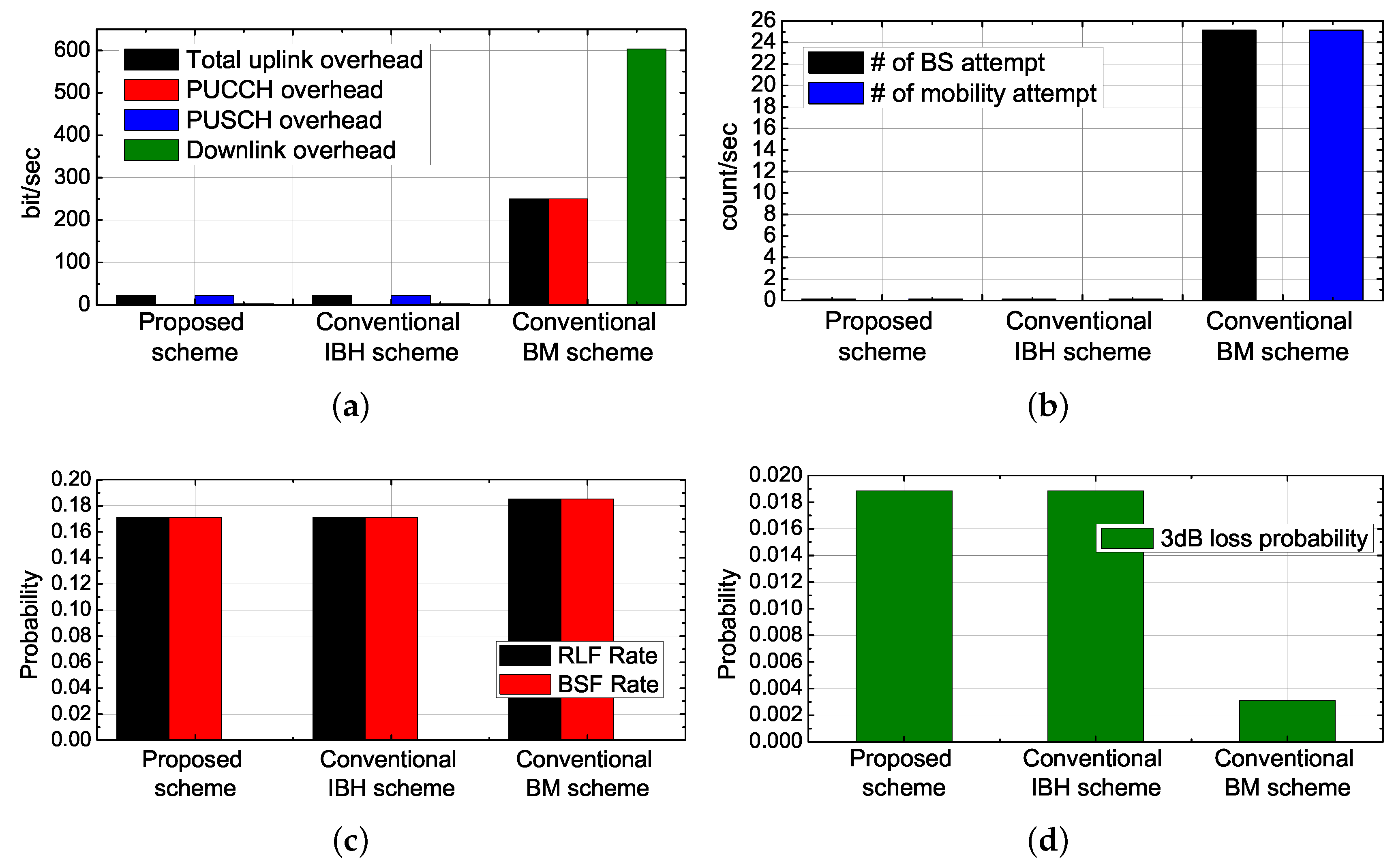
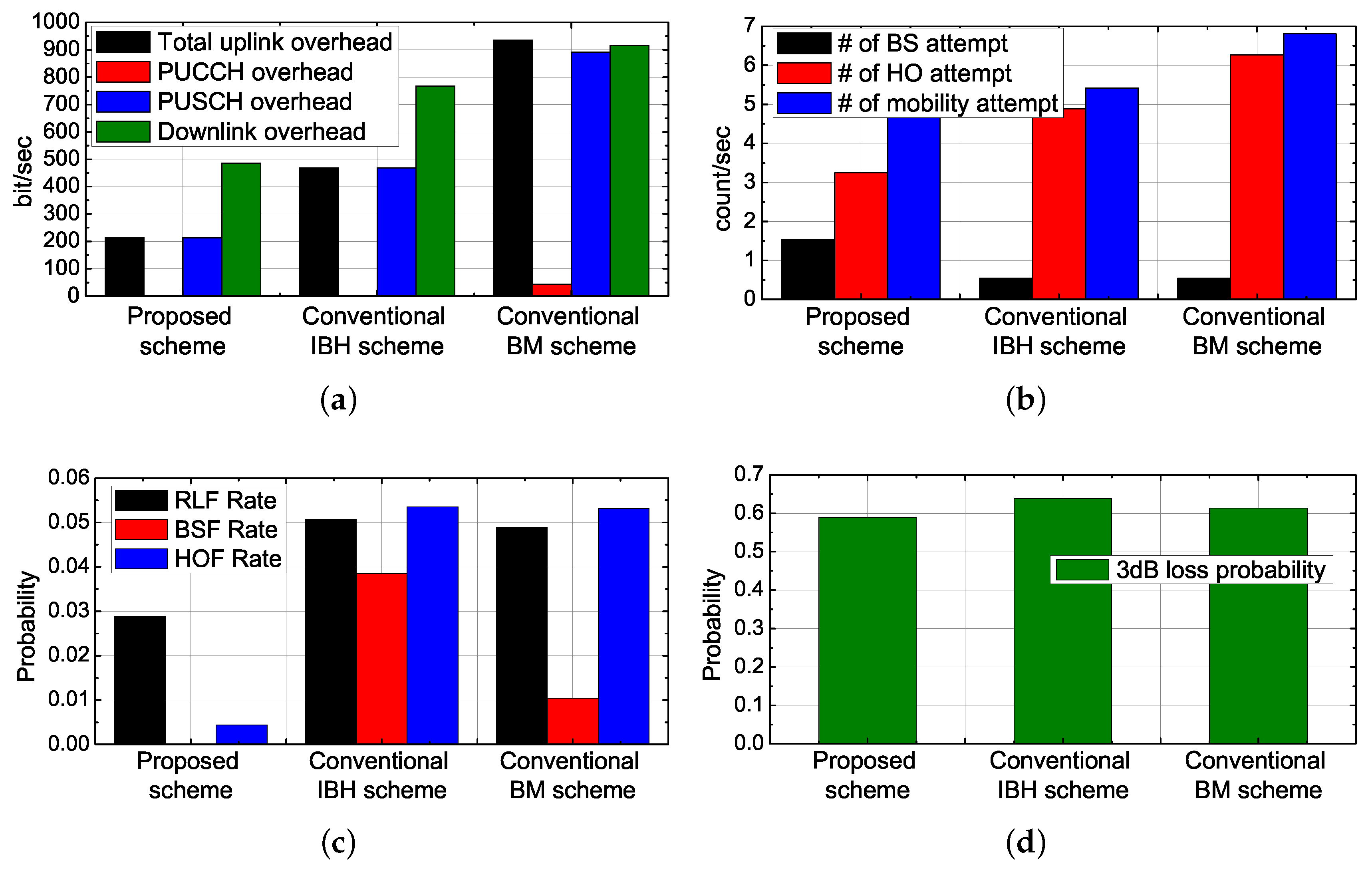
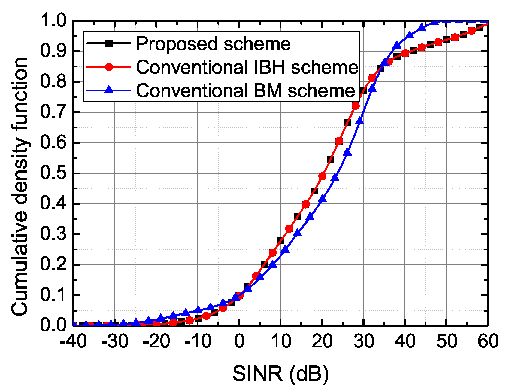
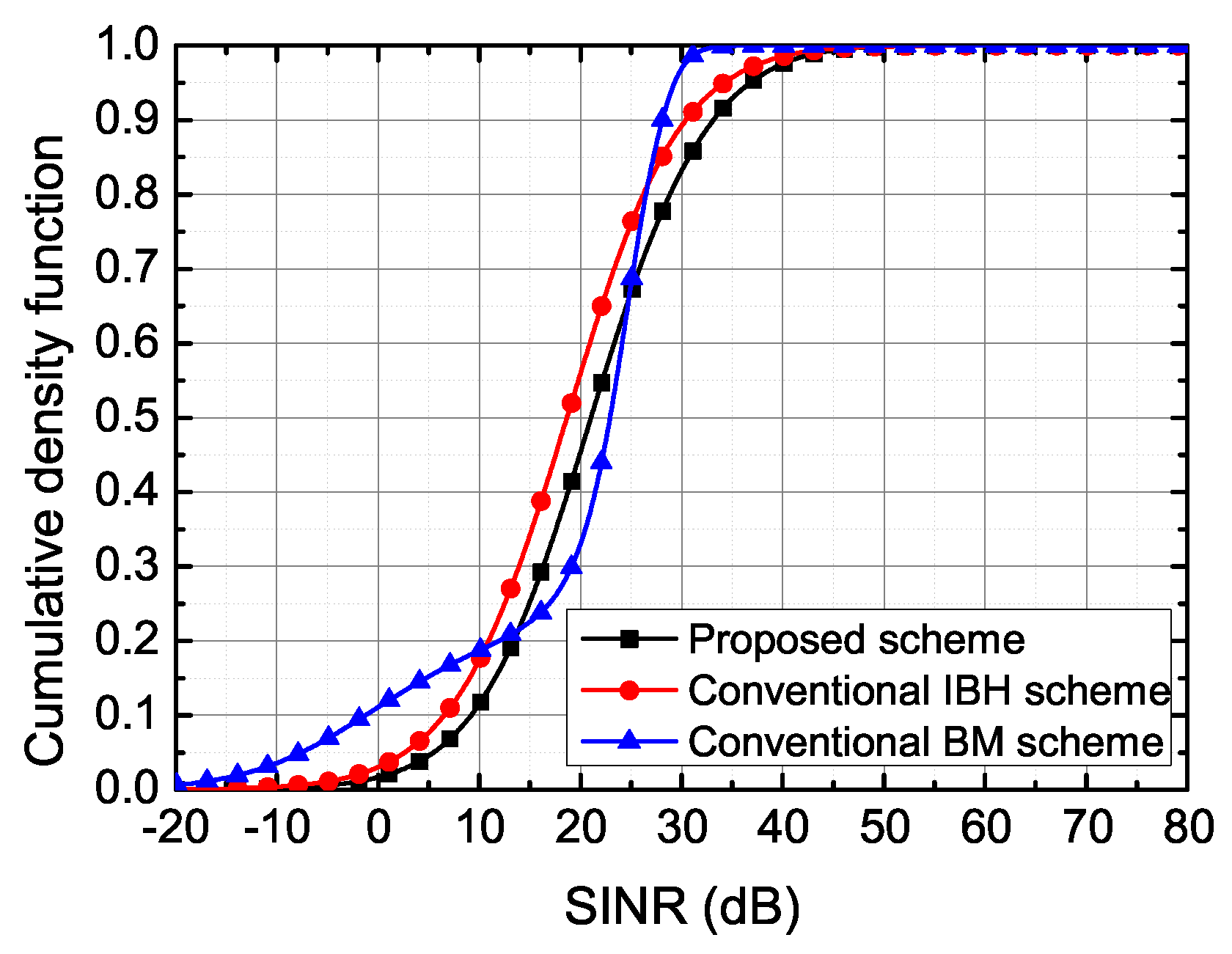
5.2. Performance Evaluation

We compare the performance of the proposed scheme with the conventional inter-beam-handover (IBH) scheme [25] and beam management (BM) scheme [18,43,44]. We consider that the period of CSI-RS report in the conventional BM scheme is four slots. We show the performance result in single-gNB and UDN environments, respectively. First, we show uplink overhead performance by the PUCCH, PUSCH, and total uplink overhead. Total uplink overhead is the sum of PUCCH and PUSCH overhead. PUCCH and PUSCH overhead is calculated by (16) and (17). Furthermore, we show the downlink overhead performance, and the results of the successful mobility attempts. That is, downlink overhead performance is obtained by M BS × number of BS attempts × ( 1 BSF rate ) + M HO × number of HO attempts × ( 1 HOF rate ) . In addition, we show the 3-dB loss probability calculated by (18). The beam switching failure (BSF), HOF, RLF rates are counted by the result of the scenarios in Figure 3. We show the SINR results calculated based on (8).
In the single-gNB case, there is no cell-level mobility but beam-level mobility. Figure 4 shows the results of the overhead, the number of mobility attempts, and the number of mobility failure under the single-gNB scenario for three schemes. Because there is no cell-level mobility, all results are presented in terms of intra-cell and inter-beams performance. The result shows that the total uplink overhead in the proposed scheme and the conventional IBH scheme is smaller than that in the conventional BM scheme. This is because the proposed scheme and the conventional IBH scheme send MR only after TTT expiry, whereas the conventional BM scheme sends the CSI-RS report every 4 ms. Users with the proposed scheme use PUSCH to send the MR while users with the conventional BM use PUCCH to send the periodic CSI-RS report. The PUCCH load is more significant than the PUSCH load in terms of uplink overhead because each user requires PUCCS independently while PUSCH can be shared by users and this. This fact is a significant factor for the overhead usage for densely deployed users, which is another advantage of the proposed scheme, particularly for the 5G NR systems. Due to the considerably high number of beam reports, there are many occurrences of beam switching in the conventional BM case that results in significant downlink overhead requirements. This indicates that the proposed scheme has a better performance in downlink overheads compared to that of the conventional BM scheme. We find that the 3-dB loss probability performance with the proposed scheme is slightly lower than that with the conventional BM case. This is because the BM scheme’s frequent periodic report makes it easier for refined TRP compared to event-triggered MR. However, it may lead to a mobility failure caused by early-beam switching, and the RLF and BSF rates are worse than those of the proposed scheme.
In Figure 5a, the proposed scheme shows considerable performance improvement compared to the conventional schemes in the practical environment system of the UDN scenario. Owing to the massive number of the measurement targets (cell and beams) and the environment where both cell-level and beam-level mobilities occur, there are two main differences between the single-gNB and UDN environments. First, overall overhead and mobility attempts are increased in UDN environments compared to the single-gNB environments as shown in Figure 5a,b. Second, the proposed scheme significantly outperforms the conventional IBH scheme in practical UDN environments in terms of the overhead and RLF rate performance. Furthermore, the proposed scheme also clearly outperforms the other two conventional schemes in terms of the mobility attempts performance. If there are many adjacent cells and available beams and if the system can provide a better channel status with beam switching, the BS is considered as a better solution than the handover because of the overhead saving. As shown in Figure 5b, the proposed scheme provides more BS attempts than the other two schemes while maintaining the minimum number of total mobility attempts. In Figure 5c,d, the proposed scheme shows the best 3-dB loss probability and the lowest RLF rate. Thus, with the proposed scheme, the system can provide better channel quality to users while the uplink and downlink overhead are kept low.
Figure 6 and Figure 7 show the SINR distribution of users in the single-gNB and UDN environment, respectively. In the single-gNB case as shown in Figure 6, the IBH and the proposed scheme show the same performances while the conventional BM scheme shows slightly better performance due to better TRP selection based on highly frequent CSI-RS report which causes significant overhead usage. However, in the UDN case as shown in Figure 7, owing to better accuracy of beam-pair selection (i.e., 3-dB loss probability) of the proposed scheme, the SINR also shows superior performance than the other two schemes. In particular, in terms of the SINR of the 5-% tile (i.e., the meaning of the outage performance), the proposed scheme is superior to the other schemes. If we use the multi-user-MIMO for increased throughput, the spectral efficiency performance of the proposed scheme can be worse than that of the BM scheme. This is because frequent periodic CSI-RS reports of the BM scheme makes it easier to find multiple-independent channel links. However, if we apply the periodic report in the proposed scheme as in the conventional BM scheme, we can achieve increased spectral efficiency by sacrificing the overhead performance as a trade-off.

6. Conclusions

In this paper, we proposed a mobility management scheme for 5G mmWave massive MIMO networks based on the unific measurement report for both cell-level handover and beam-level switching. We proposed a novel user’s state machine to evaluate the mobility performance for a practical 5G mobile communication system. With the state machine, we evaluated several important performance metrics such as uplink and downlink overhead, RLF rates, SINR, and accuracy of beam-pair selection in the system-level-simulation. Our algorithm obtained higher gain of the performance under the UDN scenario compared to the scenario of the single-gNB in terms of overhead and RLF rates compared to the conventional schemes. Therefore, the proposed scheme showed more effective results under the practical scenario where both handover and beam switching are considered rather than an ideal scenario where only beam-switching is considered as in the previous works. Furthermore, our algorithm achieved considerable improvements in terms of overhead performance, low RLF rates, the accuracy of beam pair selection, and SINR performances in the environment close to the practical system.

Author Contributions

Conceptualization, Y.J., J.L., and D.H.; methodology, Y.J.; software, Y.J.; validation, J.L. and D.H.; investigation, Y.J.; resources, Y.J. and J.L.; data curation, Y.J. and J.L.; writing—original draft preparation, Y.J.; writing—review and editing, J.L., D.H.; visualization, Y.J. and J.L.; supervision, D.H.; project administration, D.H.; Funding acquisition, J.L. and D.H. All authors have read and agreed to the published version of the manuscript.

Funding

This work was supported in part by the Institute for Information and Communications Technology Promotion (IITP) grant funded by the Korean Government (MSIT, No.2017-0-00316, Development of Fundamental Technologies for the Next, Generation Public Safety Communications), and the Basic Science Research Program through the National Research Foundation (NRF) funded by the Korea government (MIST) (No. NRF-2019R1I1A1A01058976).

Conflicts of Interest

The authors declare no conflicts of interest.

Abbreviations

The following abbreviations are used in this manuscript:
5G NRFifth-generation new radio
AASActive antenna array system
BMBeam management
BSBeam switching
BSFBeam switching failure
CSI-RSChannel state information reference signal report
FSMFinite-state-machine
gNBNext-generation-Node-B
HOHandover
HOFHandover failure
IAInitial access
IBHInter-beam-handover
LOSLine-of-sight
MMIMO(massive MIMO)Massive multiple-input-multiple-output
MRMeasurement-report
NLOSNon-line-of-sight
PUCCHPhysical-uplink-control-channel
PUSCHPhysical-uplink-shared-channel
QoSQuality-of-service
RLFRadio Link failure
RSRPReference-signal-received-power
RxReceiver
SINRSignal-to-interference-and-noise-ratio
SLSSystem-level-simulation
SSBSynchronization-symbol-burst
TRPTx-Rx beam-pair
TTTTime-to-trigger
TxTransmitter
UDNUltra-dense-networks
ULAUniform-linear-array

References

  1. Busari, S.A.; Huq, K.M.S.; Mumtaz, S.; Dai, L.; Rodriguez, J. Millimeter-wave massive MIMO communication for future wireless systems: A survey. IEEE Commun. Surv. Tutor. 2018, 20, 836–869. [Google Scholar] [CrossRef]
  2. Zhang, H.; Liu, N.; Chu, X.; Long, K.; Aghvami, A.H.; Leung, V.C. Network slicing based 5G and future mobile networks: Mobility, resource management, and challenges. IEEE Commun. Mag. 2017, 55, 138–145. [Google Scholar] [CrossRef]
  3. Bjornson, E.; Van der Perre, L.; Buzzi, S.; Larsson, E.G. Massive MIMO in Sub-6 GHz and mmWave: Physical, practical, and use-case differences. IEEE Wirel. Commun. 2019, 26, 100–108. [Google Scholar] [CrossRef] [Green Version]
  4. Zhang, J.; Ge, X.; Li, Q.; Guizani, M.; Zhang, Y. 5G millimeter-wave antenna array: Design and challenges. IEEE Wirel. Commun. 2017, 24, 106–112. [Google Scholar] [CrossRef]
  5. 3GPP TS 38.802, v14.2.0, Release 14, Study on New Radio Access Technology Physical Layer Aspects (Release 14). 2017. Available online: https://portal.3gpp.org/desktopmodules/Specifications/SpecificationDetails.aspx?specificationId=3066 (accessed on 22 May 2020).
  6. Liu, J.; Au, K.; Maaref, A.; Luo, J.; Baligh, H.; Tong, H.; Lorca, J. Initial access, mobility, and user-centric multi-beam operation in 5G new radio. IEEE Commun. Mag. 2018, 56, 35–41. [Google Scholar] [CrossRef]
  7. Hur, S.; Yu, H.; Park, J.; Roh, W.; Bas, C.U.; Wang, R.; Molisch, A.F. Feasibility of mobility for millimeter-wave systems based on channel measurements. IEEE Commun. Mag. 2018, 56, 56–63. [Google Scholar] [CrossRef]
  8. Tayyab, M.; Gelabert, X.; Jäntti, R.A. Survey on Handover Management: From LTE to NR. IEEE Access 2019, 7, 118907–118930. [Google Scholar] [CrossRef]
  9. Polese, M.; Giordani, M.; Mezzavilla, M.; Rangan, S.; Zorzi, M. Improved Handover Through Dual Connectivity in 5G mmWave Mobile Networks. IEEE J. Sel. Areas Commun. 2017, 35, 2069–2084. [Google Scholar] [CrossRef] [Green Version]
  10. Choi, J.H.; Shin, D.J. Generalized RACH-Less Handover for Seamless Mobility in 5G and Beyond Mobile Networks. IEEE Wirel. Commun. Lett. 2019, 8, 1264–1267. [Google Scholar] [CrossRef]
  11. Alhammadi, A.; Roslee, M.; Alias, M.Y.; Shayea, I.; Alraih, S.; Mohamed, K.S. Auto Tuning Self-Optimization Algorithm for Mobility Management in LTE-A and 5G HetNets. IEEE Access 2019, 8, 294–304. [Google Scholar] [CrossRef]
  12. Zhang, Z.; Junhui, Z.; Ni, S.; Gong, Y.A. Seamless Handover Scheme with Assisted eNB for 5G C/U Plane Split Heterogeneous Network. IEEE Access 2019, 7, 164256–164264. [Google Scholar] [CrossRef]
  13. Zhang, H.; Huang, W.; Liu, Y. Handover probability analysis of anchor-based multi-connectivity in 5G user-centric network. IEEE Wirel. Commun. Lett. 2019, 8, 396–399. [Google Scholar] [CrossRef]
  14. Semiari, O.; Saad, W.; Bennis, M.; Maham, B. Caching meets millimeter wave communications for enhanced mobility management in 5G networks. IEEE Trans. Wirel. Commun. 2018, 17, 779–793. [Google Scholar] [CrossRef]
  15. 3GPP TS 38.300, v15.3.1, Release 15, 5G; NR; Overall description; Stage-2. 2018. Available online: https://portal.3gpp.org/desktopmodules/Specifications/SpecificationDetails.aspx?specificationId=3191 (accessed on 22 May 2020).
  16. 3GPP TS 38.331, v15.8.0, Release 15, NR; Radio Resource Control (RRC) Protocol Specification (Release 15). 2019. Available online: https://portal.3gpp.org/desktopmodules/Specifications/SpecificationDetails.aspx?specificationId=3197 (accessed on 22 May 2020).
  17. Giordani, M.; Polese, M.; Roy, A.; Castor, D.; Zorzi, M. A tutorial on beam management for 3GPP NR at mmWave frequencies. IEEE Commun. Surv. Tutor. 2019, 21, 173–196. [Google Scholar] [CrossRef] [Green Version]
  18. Li, Y.N.R.; Gao, B.; Zhang, X.; Huang, K. Beam Management in Millimeter-Wave Communications for 5G and Beyond. IEEE Access 2019, 8, 13282–13293. [Google Scholar] [CrossRef]
  19. Giordani, M.; Polese, M.; Roy, A.; Castor, D.; Zorzi, M. Standalone and Non-Standalone Beam Management for 3GPP NR at mmWaves. IEEE Commun. Mag. 2019, 57, 123–129. [Google Scholar] [CrossRef] [Green Version]
  20. Souto, V.D.P.; Souza, R.D.; Uchôa-Filho, B.F.; Li, Y. A Novel Efficient Initial Access Method for 5G Millimeter Wave Communications Using Genetic Algorithm. IEEE Trans. Veh. Technol. 2019, 68, 9908–9919. [Google Scholar] [CrossRef]
  21. Raghavan, V.; Partyka, A.; Sampath, A.; Subramanian, S.; Koymen, O.H.; Ravid, K.; Li, J. Millimeter-Wave MIMO Prototype: Measurements and Experimental Results. IEEE Commun. Mag. 2018, 56, 202–209. [Google Scholar] [CrossRef] [Green Version]
  22. Sung, N.W.; Choi, Y.S. Method and Apparatus for Beam Switching in Mobile Communication Network. U.S. Patent No. 10,004,077, 19 June 2018. [Google Scholar]
  23. Ren, W.; Xu, J.; Li, D.; Cui, Q.; Tao, X. A Robust Inter Beam Handover Scheme for 5G mmWave Mobile Communication System in HSR Scenario. In Proceedings of the 2019 IEEE Wireless Communications and Networking Conference (WCNC), Marrakech, Morocco, 15–19 April 2019; pp. 1–6. [Google Scholar]
  24. Jayaprakasam, S.; Ma, X.; Choi, J.W.; Kim, S. Robust beam-tracking for mmWave mobile communications. IEEE Commun. Lett. 2017, 21, 2654–2657. [Google Scholar] [CrossRef]
  25. Oh, S.M.; Kang, S.Y.; Go, K.C.; Kim, J.H.; Park, A.S. An Enhanced Handover Scheme to Provide the Robust and Efficient Inter-Beam Mobility. IEEE Commun. Lett. 2015, 19, 739–742. [Google Scholar] [CrossRef]
  26. Liu, Y.; Fang, X.; Xiao, M.; Mumtaz, S. Decentralized beam pair selection in multi-beam millimeter-wave networks. IEEE Trans. Commun. 2018, 66, 2722–2737. [Google Scholar] [CrossRef]
  27. 3PGG TR 38.133, v.15.3.0, Release 15, 5G; NR; Requirements for Support of Radio Resource Management. 2018. Available online: https://portal.3gpp.org/desktopmodules/Specifications/SpecificationDetails.aspx?specificationId=3204 (accessed on 22 May 2020).
  28. 3GPP TR 36.839, v.11.1.0, Release 11, Evolved Universal Terrestrial Radio Access (E-UTRA); Mobility Enhancements in Heterogeneous Networks (Release 11). 2012. Available online: https://portal.3gpp.org/desktopmodules/Specifications/SpecificationDetails.aspx?specificationId=2540 (accessed on 22 May 2020).
  29. Rebato, M.; Resteghini, L.; Mazzucco, C.; Zorzi, M. Study of realistic antenna patterns in 5G mmWave cellular scenarios. In Proceedings of the 2018 IEEE International Conference on Communications (ICC), Kansas City, MO, USA, 20–24 May 2018; pp. 1–6. [Google Scholar]
  30. 3GPP TR 37.840, v12.1.0, Technical Specification Group Radio Access Network; Study of Radio Frequency (RF) and Electromagnetic Compatibility (EMC) Requirements for Active Antenna Array System (AAS) Base Station (Release 12). 2013. Available online: https://portal.3gpp.org/desktopmodules/Specifications/SpecificationDetails.aspx?specificationId=2624 (accessed on 22 May 2020).
  31. Akdeniz, M.R.; Liu, Y.; Samimi, M.K.; Sun, S.; Rangan, S.; Rappaport, T.S.; Erkip, E. Millimeter wave Channel modeling and cellular capacity evaluation. IEEE J. Sel. Areas Commun. 2014, 32, 1164–1179. [Google Scholar] [CrossRef]
  32. Sun, S.; Thomas, T.A.; Rappaport, T.S.; Nguyen, H.; Kovacs, I.Z.; Rodriguez, I. Path loss, shadow fading, and line-of-sight probability models for 5G urban macro-cellular scenarios. In Proceedings of the 2015 IEEE Globecom Workshops (GC Wkshps), San Diego, CA, USA, 6–10 December 2015; pp. 1–7. [Google Scholar]
  33. Samimi, M.K.; MacCartney, G.R.; Sun, S.; Rappaport, T.S. 28 GHz millimeter-wave ultrawideband small-scale fading models in wireless channels. In Proceedings of the 2016 IEEE 83rd Vehicular Technology Conference (VTC Spring), Nanjing, China, 15–18 May 2016; pp. 1–6. [Google Scholar]
  34. Kammoun, A.; Debbah, M.; Alouini, M.S. Design of 5G full dimension massive MIMO systems. IEEE Trans. Commun. 2018, 66, 726–740. [Google Scholar]
  35. Samimi, M.K.; Sun, S.; Rappaport, T.S. MIMO channel modeling and capacity analysis for 5G millimeter-wave wireless systems. In Proceedings of the 2016 10th European Conference on Antennas and Propagation (EuCAP), Davos, Switzerland, 10–15 April 2016; pp. 1–5. [Google Scholar]
  36. Bai, T.; Heath, R.W. Coverage and rate analysis for millimeterwave cellular networks. IEEE Trans. Wireless Commun. 2015, 14, 1100–1114. [Google Scholar] [CrossRef]
  37. Rebato, M.; Mezzavilla, M.; Rangan, S.; Boccardi, F.; Zorzi, M. Understanding noise and interference regimes in 5G millimeter-wave cellular networks. In Proceedings of the European Wireless 2016 22th European Wireless Conference, Oulu, Finland, 18–20 May 2016; pp. 1–5. [Google Scholar]
  38. Samimi, M.K.; Rappaport, T.S.; MacCartney, G.R. Probabilistic omnidirectional path loss models for millimeter-wave outdoor communications. IEEE Wireless Commun. Lett. 2015, 4, 1–4. [Google Scholar] [CrossRef]
  39. Guo, W.; Zhang, W.; Mu, P.; Gao, F.; Lin, H. High-mobility wideband massive MIMO communications: Doppler compensation, analysis and scaling laws. IEEE Trans. Wireless Commun. 2019, 18, 3177–3191. [Google Scholar] [CrossRef]
  40. 3GPP TS 38.212, v15.8,0, Release 15, NR; Multiplexing and Channel Coding (Release 15). 2019. Available online: https://portal.3gpp.org/desktopmodules/Specifications/SpecificationDetails.aspx?specificationId=3214 (accessed on 22 May 2020).
  41. Va, V.; Shimizu, T.; Bansal, G.; Heath, R.W. Online learning for position aided millimeter wave beam training. IEEE Access 2019, 7, 30507–30526. [Google Scholar] [CrossRef]
  42. 3GPP TS 38.331, v15.3.0, Release 15, NR; Radio Resource Control (RRC) Protocol Specification (Release 15). 2019. Available online: https://portal.3gpp.org/desktopmodules/Specifications/SpecificationDetails.aspx?specificationId=3197 (accessed on 22 May 2020).
  43. 3GPP ZTE. Details and LLS Evaluation on L1-SINR Measurement and Reporting, document RAN1 R1-1906248, RAN1#97; 3GPP ZTE: Reno, NV, USA, 2019. [Google Scholar]
  44. 3GPP ZTE. Details and SLS Evaluation on L1-SINR Measurement and Reporting, document RAN1 R1-1906249, RAN1#97; 3GPP ZTE: Reno, NV, USA, 2019. [Google Scholar]
Figure 1. Example of the beam pattern in relation to L = 3 case. (a) beam pattern configuration in Cartesian (left plot) and polar (right plot) coordinate systems with G t ( 0 ) , (b) beam pattern configuration in Cartesian (left plot) and polar (right plot) coordinate systems with G t ( 1 ) , (c) beam pattern configuration in Cartesian (left plot) and polar (right plot) coordinate systems with G t ( 2 ) .
Electronics 09 00865 g001
Figure 2. Beam switching process in the proposed scheme.
Electronics 09 00865 g002
Figure 3. User finite state machine for proposed scheme.
Electronics 09 00865 g003
Figure 4. Simulation results in single-gNB environment. (a) overhead performance, (b) mobility attempts, (c) mobility failure rates, (d) 3 dB-loss probability.
Electronics 09 00865 g004
Figure 5. Results under the UDN scenario. (a) overhead performance, (b) mobility attempts, (c) mobility failure rates, (d) 3-dB loss probability.
Electronics 09 00865 g005
Figure 6. SINR results in relation to 3-schemes in single-gNB environment.
Electronics 09 00865 g006
Figure 7. SINR results in relation to 3-schemes in the UDN environment.
Electronics 09 00865 g007
Table 1. Description of symbols.
SymbolDescription
θ , θ s Vertical angle, main beam direction of vertical angle
ϕ , ϕ s Horizontal angle, main beam direction of horizontal angle
pIndex of the antenna elements in horizontal direction
rIndex of the antenna elements in vertical direction
I Set of users in the system
iIndex of the user
L Set of main beam candidates
l, l s Index of the beam, index of the serving beam for i-th user
K Set of cells in the system
k, k s Index of the cell, index of the serving cell for i-th user
dDistance between user and cell in meter
B Set of possible beam-pair between user and cell
Table 2. System parameters.
Parameter DescriptionSymbolValue
Carrier frequency f c 28 GHz
System bandwidth B W 500 MHz
Pathloss probability coefficients a out , b out , a LOS 1 / 30.0 m, 5.2 , 1 / 67.1 [32,37,38]
Pathloss coefficients α LOS , β LOS , α NLOS , β NLOS 61.4 , 2, 72.0 , 2.92 [32,37,38]
Standard deviation for log-normal shadow fading σ LOS , σ NLOS 5.8 dB, 8.7 [32,37,38]
Time to trigger T T T 40 ms [16]
Entering and escaping threshold of state S 1 Q out , k s , Q in , k s 8 dB, 5 dB [16]
Waiting timer to decide to escape from state S 1 T 310 50 ms [16]
Bits for SSB and CSI-RS ID K s SSB , K s CSI - RS 6 bits, 4 bits [40]
Bits for RSRP and default MR M RSRP , M default 7 bits, 184 bits [25,40]
Bits for downlink BS command M BS 28 bits [25]
Bits for downlink HO command M HO 288 bits [25]

