Article

Electrical Material Properties of Carbon Reinforced Concrete

1
Chair of Radio Frequency and Photonics Engineering, Dresden University of Technology, 01062 Dresden, Germany
2
Institute of Concrete Structures, Dresden University of Technology, 01062 Dresden, Germany
*
Author to whom correspondence should be addressed.
Now with sbp schlaich bergermann partner, Stuttgart, Germany.
Electronics 2020, 9(5), 857; https://doi.org/10.3390/electronics9050857
Submission received: 30 April 2020 / Revised: 17 May 2020 / Accepted: 19 May 2020 / Published: 21 May 2020
(This article belongs to the Section Microwave and Wireless Communications)

Abstract

:
Carbon fiber reinforced concrete is poised to be the building material of the future. We present a study to quantify the influence of this novel reinforcement material on RF propagation in the range from 0.4 to 67 GHz. The measured attenuation effects of the reinforcement material are explained and quantified using a metallic wire screen model. It can be used to as a simple model of the material’s influence in radio propagation scenarios. For reference and completeness, data on the complex dielectric permittivity of the investigated concrete brand is also included. The production process of the concrete samples used for the measurements is documented, facilitating comparability and reproducibility. Finally, implications for current and future radio communication applications are outlined.

1. Introduction

Concrete has been a well-known building material for more than 2000 years, with Rome’s Pantheon, still the world’s largest cupola made of unreinforced concrete, as the prime example [1]. Since the mid-19th century, concrete is reinforced by iron and later steel, in order to improve its performance under tensile load. Today, concrete is the world’s most used construction material, and steel the most used reinforcement material. However, steel can corrode, which causes massive damage to buildings and thereby immense repair costs.
Carbon fiber is considered as an alternative reinforcement material, due to the advantageous mechanical and chemical properties, as well as the great concrete saving potential [2,3].
This paper presents a study of the influence of the new reinforcement material on the propagation of electromagnetic waves in the frequency range from 400 M Hz to 67 GHz, covering nearly all currently relevant radio communication standards, as well as most of the bands considered for the 5G standard(s) [4]. The presented data is intended to serve as a basis for propagation and communication link modeling for indoor and urban scenarios. In order to ensure comparability of results, the investigated concrete samples are produced under laboratory conditions, and their composition, curing, and processing is documented.

2. State of the Art

2.1. Carbon Reinforced Concrete

Carbon reinforcement is made of carbon fiber filament threads impregnated with a coating. The coating makes sure that all filaments participate in the transfer of the mechanical load, and improve compounding between concrete and reinforcement. Depending on the desired final stiffness, different agents, for example, styrene-butadiene rubber (SBR) or epoxy-based resins, can be used.
Just as traditional steel reinforcement, carbon fiber reinforcement is produced as gridded mats or as rebar rod, see Figure 1. For the gridded mats, the distance between the threads is in the range of 0.5 to 5 cm, depending on the purpose. This is much smaller than traditional steel reinforcement, where the grid distance is usually in the order of 5 to 20 cm [5]. As an alternative to carbon fiber, alkali-resistant (AR) glass or basalt fiber can be used. Table 1 contains guideline values for mechanical parameters of different reinforcement materials. It can be seen that at about a quarter of the density of steel, the tensile strength of carbon fiber is at least five times higher, making it theoretically 20 times more efficient per unit of load carried [6].
In Reference [7], measurements of the electrical properties of carbon fiber are presented. The conductivity was measured to be between 10 2 to 10 3 S/cm for a single fiber with 5 μm diameter. A cross comparison of 85 different commercially available continuous carbon fiber products [8] gives an average value of 6.63 × 10 2 S/cm, three orders of magnitude worse than copper ( 6 × 10 5 S/cm at room temperature) [9], and therefore still a reasonably good electrical conductor.
Considering concrete, the range of used materials is wide, from ultra high performance concrete (UHPC) to standard “regular” concrete. The concrete’s composition is chosen depending on the performance requirements of the structural member, the production procedure, and the used reinforcement. Carbon concrete is the composition of concrete with a reinforcement made of carbon fiber. Thanks to the rustproof reinforcements, the coverage height, that is, the thickness of the concrete atop the reinforcement, can be minimized. The coverage height needs to be at least 16 to 60 m m for steel reinforcement, depending on the location (indoor or outdoor). With carbon reinforcement, the coverage height can be reduced to 5 m m . With the lower thickness of carbon reinforcement compared to steel, the minimum achievable total thickness of a concrete construction component can be reduced from 80 m m to 20 m m , thereby ideally saving up to 75% material [2,3].
Carbon reinforced concrete is already used for the reinforcement of buildings and bridges [6,11], as well as for walls and façades. The build permit for the first house made completely of carbon concrete has recently been issued [12].

2.2. Characterization of RF Properties of Building Materials

In Reference [13], a review of material characterization efforts for building material is presented. The authors criticize the lack of comparability between the different published data, because documentation of the material composition and fabrication process are not included. In Reference [14], diverging data compiled from different sources is presented as well. As concrete is a very diverse building material, characterized by for example, the mixture ratio of filling aggregate, cement and water, the use of chemical or mineral admixtures, the grain size of the filling aggregate, and so forth, comparability indeed cannot be guaranteed. Sandrolini et al. [15] discusses the influence of the water content on the dielectric material properties up to 1 GHz. In Reference [16], different buildings are investigated with regard to “building entry loss” for communications links in the range 0.1 to 6 GHz, albeit with a focus on the influence of new energy-efficient construction practices. Material measurements of concrete up to 10 GHz are presented in Reference [17].
Steel rebar reinforcement is investigated in References [18,19,20], where numerical analyses based on the “Finite-difference time-domain” (FDTD) method [21] are presented for bands between 0.1 to 11 GHz, although with a stronger focus on the numerical method. All conclude that the rebar influences wave propagation to some extent, but do not quantify.

3. Investigations & Setup

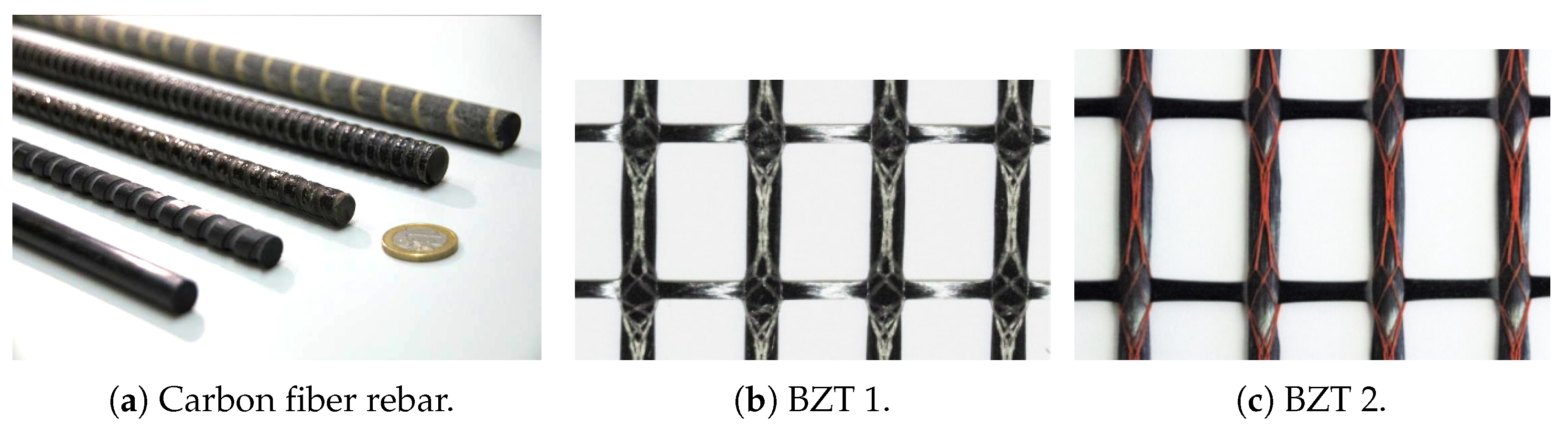
3.1. Reinforcement Material

The gridded carbon fiber mats are produced in a deposition process. A warp thread is placed atop a weft thread, maintaining a certain raster distance. Warp and weft are then joined with a stitching thread (white in Figure 1b, red in Figure 1c, usually made of polypropylene), and finally impregnated with a coating. The terms warp and weft are used for reasons of tradition, as there is no actual warping, that is, threads oriented in one direction are always atop the other direction’s threads. The thicker warp threads usually have a density of 3300 to 3600 tex . A density of 800 tex is common for the thinner weft threads, but depending on the application, they can be as thick as the warps.
The commercially available reinforcement materials, namely BZT 1 (Figure 1b, complete name “TUDALIT-BZT1-TUDATEX”) and BZT 2 (Figure 1c, complete name “TUDALIT-BZT2-V.FRAAS”) were used, both coated with Lefasol VLT-1. The measurements of the reinforcement material were performed with a prototype material with different grid dimensions. Warp and weft dimensions of the investigated material are given in Table 2.

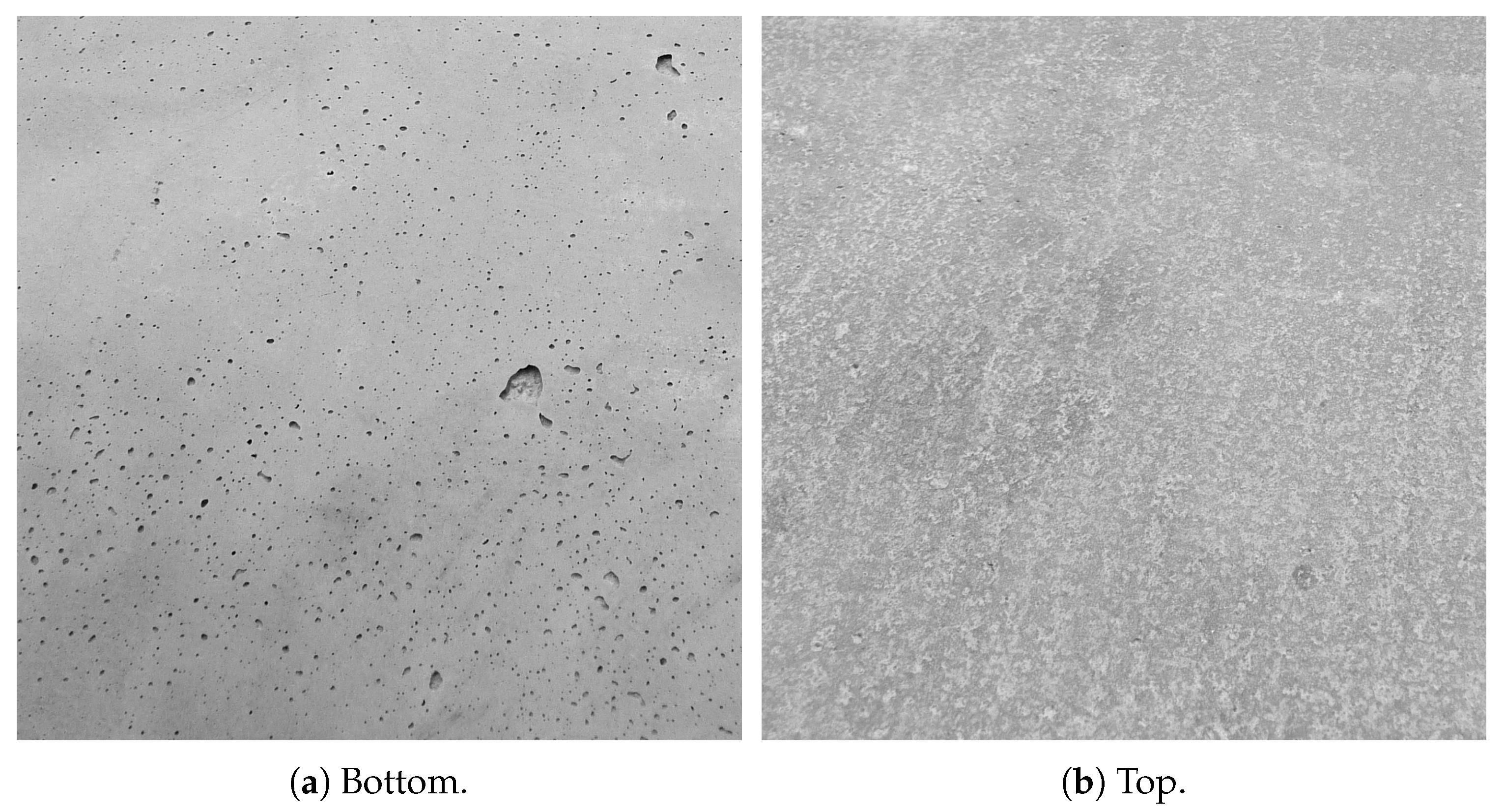
3.2. Concrete Samples & Preparation

In order to ensure comparability and reproducibility of measurement results, raw materials were chosen as laid down in “abZ Z-31.10-182” (“National Technical Approval of the General Supervisory Authority for the Building Industry”) [22].
Pagel TF10 [23], the fine concrete used for the samples, consists mainly of Portland cement and silica sand with a maximum grain diameter of 1 m m . Technically, mixtures with a maximum grain size of up to 4 m m are usually referred to as “mortar” [24,25]. In the carbon concrete environment, however, the term “fine concrete” was established in order to show the closeness to steel reinforced concrete. Common concretes have grain sizes from 0.125 m m to more than 4 m m , mostly to 32 m m , and in individual cases even to 63 m m .
For the investigations presented below, samples of different dimensions were produced, with and without reinforcement. Where reinforcement was used, it was placed at the center of the z axis. For details, see Table 3. The samples were produced by horizontal lamination, where concrete and reinforcement were added layer by layer. This allows orderly placement of the carbon reinforcement as well as position stability during concreting.
Curing of all samples was performed according to the requirements in Reference [26]. To ensure optimal hydration of the fresh concrete, the molds were covered with an airtight and water vapor tight sheet. After storage for 24 h at room temperature, the samples were stored in a water bath for six days. Then, the samples were transferred to the climate chamber with 20 C and 65% relative humidity, where they remained for 21 days.
Figure 2 shows the top and bottom surface of a flat sample of 20 m m thickness. On the bottom side, the typical pattern of air bubble inclusions, which remained in the mold during concreting, can be seen. Other than that, it is flat. The top side, however, is quite rough, in the scale of a few tenths of m m to some m m .

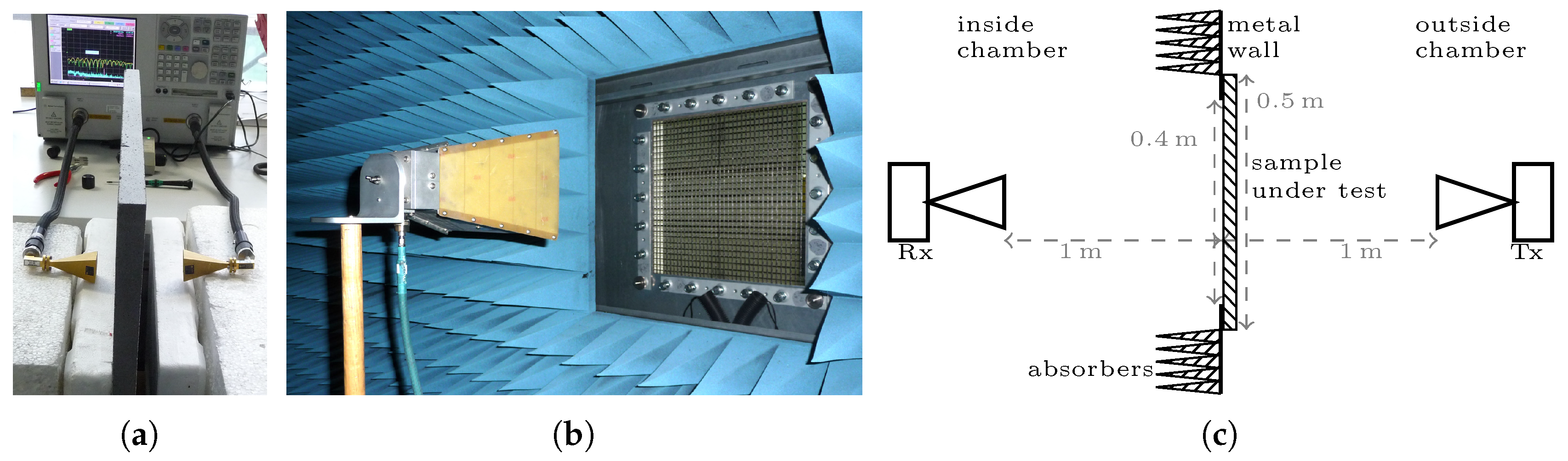
3.3. Measurement Setup

For the measurement setups described in the following, two network analyzers were used: a Keysight N9918A “FieldFox” with operating frequencies from 30 kHz to 26.5 GHz, and an Agilent PNA ( 10 M Hz to 67 GHz). In total, four pairs of antennas were used, see Table 4 for details. The R&S HL033 is a log-periodic antenna, the others are horn antennas. In order to determine the influence of the reinforcement, two different setups to measure the transmitted power were used, described in the following.

3.3.1. Measurement Window of Anechoic Chamber

The 0.4 × 0.4 m opening in the anechoic chamber was used for the measurements of the reinforcement material from 0.3 to 67 GHz as well as for the measurement of the concrete slabs up to 50 GHz, see Figure 3b,c. The antennas were positioned to directly face one another through the measurement opening of the anechoic chamber (total dimensions 8 × 6 × 3 m ), as shown in Figure 3c. The antenna outside was used as the transmitting antenna. It was fitted with absorbers. The VNA’s transmission power was set to the highest available setting in order to suppress environmental influences. As shown in Figure 3c, the distance between the antennas and the sample under test is 1 m , sufficient for the far field criterion [31]: r 5 λ 2 π 0.8 λ , the distance where the emitted radiative field dominates, and propagates with free space impedance Z 0 377 Ω . This allows measurements with this setup starting at ≈ 240 M Hz . (For antenna measurements, where the far field radiation characteristics is to be determined, other criteria are used [32]. A very useful discussion and overview can be found in Reference [31]).
This setup was chosen to cope with the constraints posed by the investigated material’s small sample size, the targeted frequency range, and the laboratory environment. Firstly, diffraction at the edges of the anechoic chamber’s window will occur. This effect will be stronger towards lower frequencies and show as a strong oscillation around the mean value, which will shift when introducing the MUT (material under test). This should be kept in mind when interpreting the measurement results. Secondly, due to the large bandwidth covered, the “transitions” between the antenna sets are not in perfect alignment, caused by the different positioning of the antennas.

3.3.2. Short-Distance Setup 50 to 67 GHz

In order to cover the frequency range from 50 to 67 GHz, a short-range setup using styrofoam boxes as support was built to measure the concrete slab samples (see Table 3), shown in Figure 3a. The antennas rest firmly on the styrofoam support, kept in place by the weight of the RF cables. The MUT is also supported by the styrofoam blocks, and fixed to the left side by small styrofoam wedges (not shown).
This setup was used for because the free-space path loss (FSPL) is prohibitively large towards higher frequencies. For a distance of 2 m, FSPL 72.4 d B for 50 GHz, so there is only a small fraction of the VNA’s dynamic range left for the measurement itself, with calibration not yet considered.

3.4. Measurement Procedure

The measurement proceeded as follows: At first, an obstacle-free measurement was done with each antenna pair, serving as transmitted power reference. Then, the MUT was placed into the measurement setup. The ratio of the received power in presence of the MUT to the reference measurement is the sought value—the transmission loss caused by the MUT.

4. Results & Discussion

4.1. Electrical Resistance at DC

In order to get a first impression of the reinforcement material, the electrical resistance was measured with a simple lab multimeter. The measured values never exceeded 10 Ω , independent of whether the probe tips touched the same thread, whether the probes touched different threads (weft or warp), or wether the carbon fiber grid mat was impregnated with SBR coating. This leads to conclude that good electrical contact is present between the fiber filaments forming the threads and between the threads themselves, and that good conductivity is still given with impregnation.

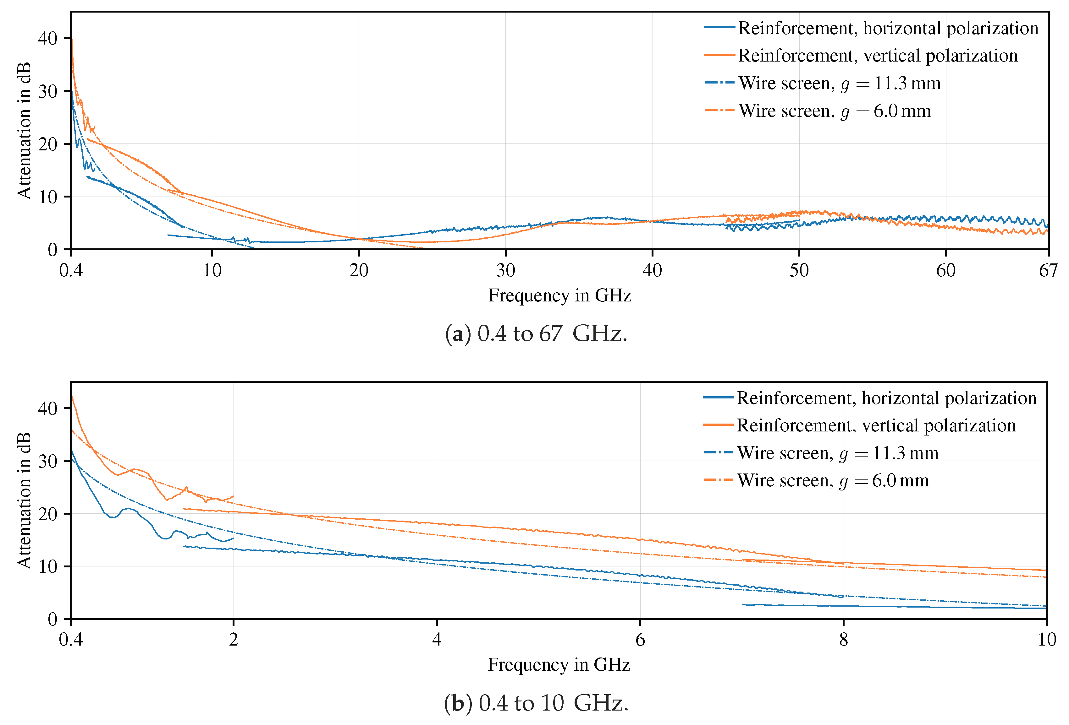
4.2. Transmission Measurements of Reinforcement Material

Figure 4 shows the attenuation measured in the frequency range of 0.4 to 67 GHz as caused by the reinforcement material only, that is, carbon fiber grid mats. Measurements in four frequency ranges, 0.4 to 2 GHz, 1.5 to 8 GHz, 7 to 50 GHz, and 50 to 67 GHz, are combined into one panel in Figure 4a. Variances, gaps and the imperfect overlap between frequency ranges can be explained by the measurement environment and the different characteristics of the used antennas, as discussed above in Section 3.3. In Figure 4b, which shows the frequency range 0.4 to 10 GHz, a strong suppression of the received signal of more than 40 dB can be seen, together with a polarization selectivity. The vertical polarization which transmits through the smaller warp thread gaps is attenuated stronger than the horizontal polarization. Below 2 GHz, oscillation is clearly visible, caused by diffraction at the measurement window’s metal edges, as discussed in Section 3.3, but luckily not as pronounced as expected.
In Reference [33], wire screens are described as “small aperture metals” and their shielding properties are investigated. Their far field shielding effectiveness SE is described by [33]:
SE dB 20 log 10 λ / 2 g 20 log 10 c 0 2 f g for g λ / 2 , SE dB 0 for g λ / 2 ,
with λ the wavelength and f the corresponding frequency, c 0 the speed of light in vacuum, and g the air gap width.
Curves following Equation (1) for g = { 6 ; 11.3 } mm (gap widths in Table 2) are included in Figure 4. It can be seen that the measured shielding effect caused by the reinforcement material follows the values predicted by theory very closely. Towards higher frequencies, the transmission loss remains at about 5 dB, which can be explained by the fact that the “optical” path is occluded, and scattering of the wave field occurs.

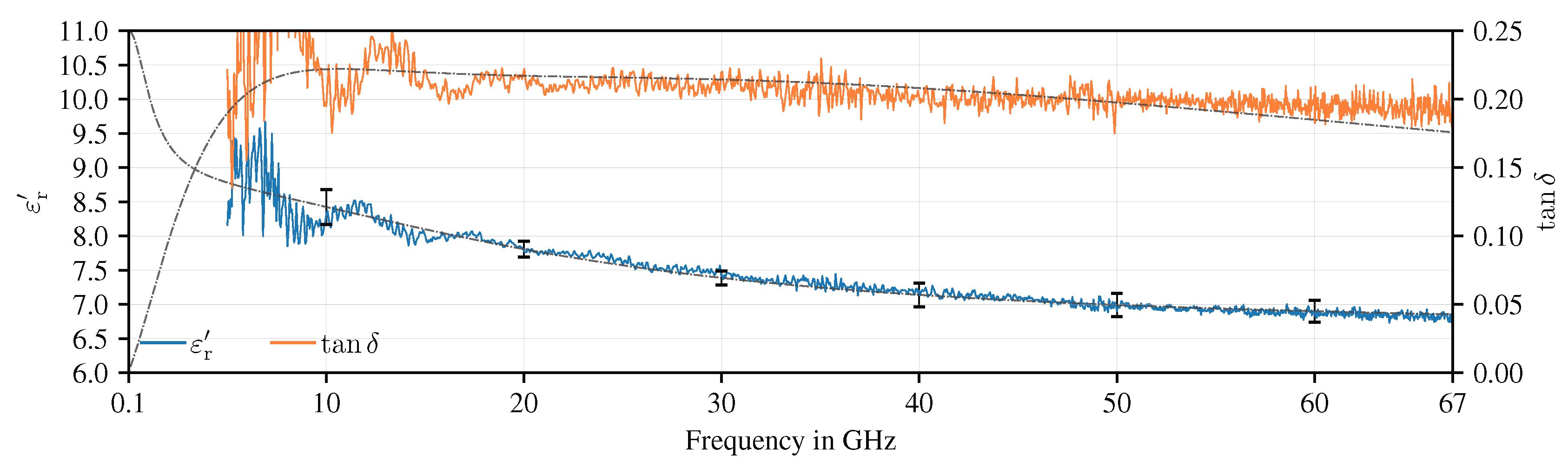
4.3. Material Properties of Concrete Samples

In Reference [34], we describe a procedure to extract the complex dielectric permittivity ε r of flat samples. The results for the Pagel TF10 fine concrete samples are given in Figure 5. The blue and orange lines show the measured values of the real part of the dielectric permittivity ε r and the corresponding dielectric loss tangent tan δ from 5 to 67 GHz. As several concrete samples are measured, mean and standard deviation for the measurements are depicted by the error bars for ε r . The grey dash-dotted lines show a fitting curve for the respective parameter, derived by a multi-pole Debye model. As can be seen, these lines follow the measured values closely. They are extrapolated based on this model to 0.1 GHz. However, the extrapolated values should be treated with caution. For an in-depth discussion see Reference [35].
In Reference [13], a linear regression for | ε r | over several measurements compiled from different literature is given with parameters | ε r | ( 0 Hz ) = 6.48 and slope n = 0.0391 / G Hz . This yields | ε r | ( 10 GHz ) = 6.09 and | ε r | ( 60 GHz ) = 4.14 , significantly lower than our measurements. This can be explained by the different composition and preparation of the investigated concrete samples, on which there is only limited documentation, as already criticized in Reference [13]. The slope is negative in both cases ( n = 0.0281 / GHz in our measured data), as expected from general theory [36], and in the same order of magnitude. General theory, however, does not predict a linear behavior over this frequency range, so care should be taken when extrapolating.

4.4. Transmission Measurements of Reinforced Concrete Slabs

As above, the transmission through concrete slabs, both with and without reinforcement, was measured. The results are presented in Figure 6 and Figure 7.

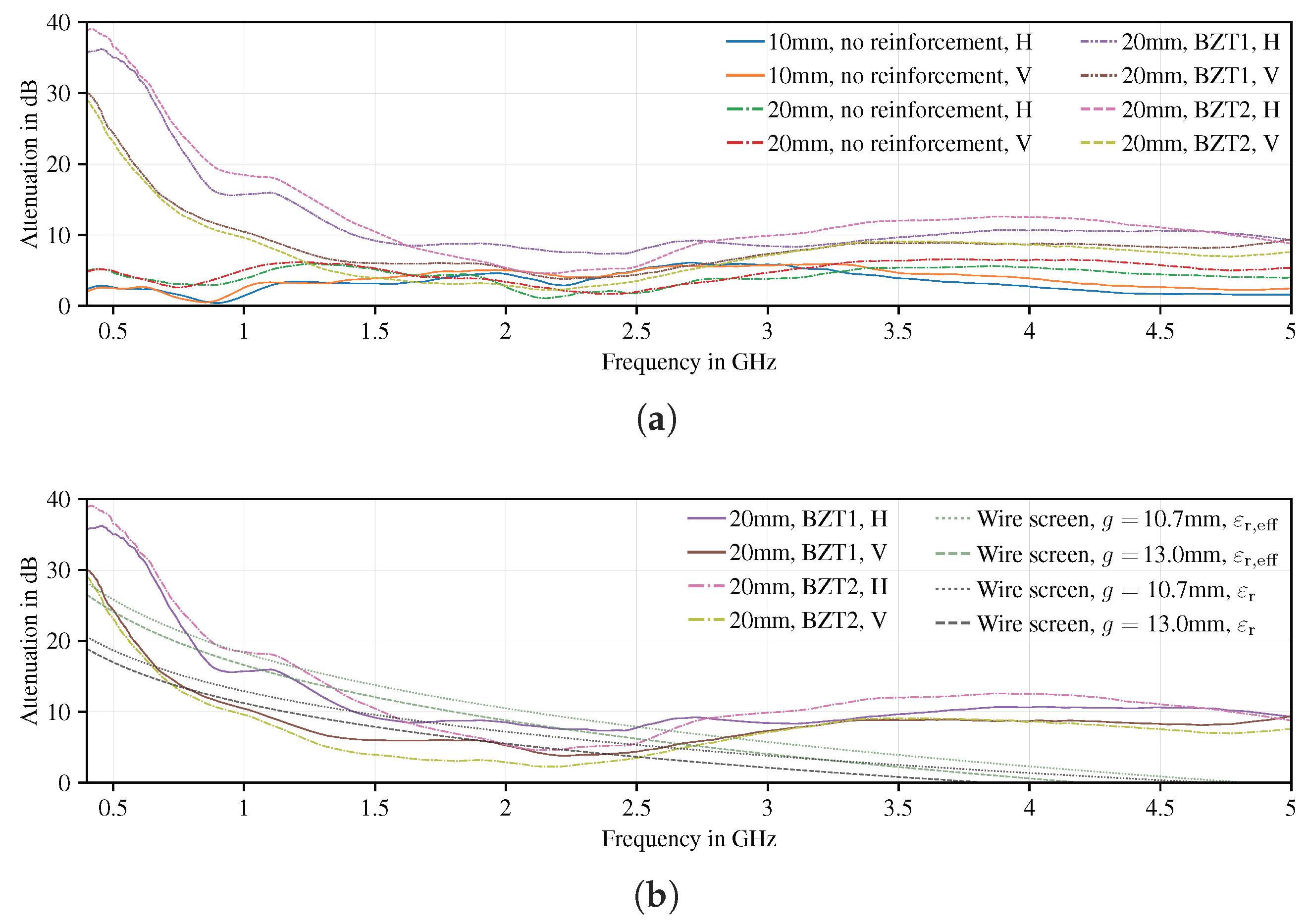
4.4.1. Influence of the Carbon Fiber Reinforcement Embedded in Concrete, 0.4 to 5 GHz
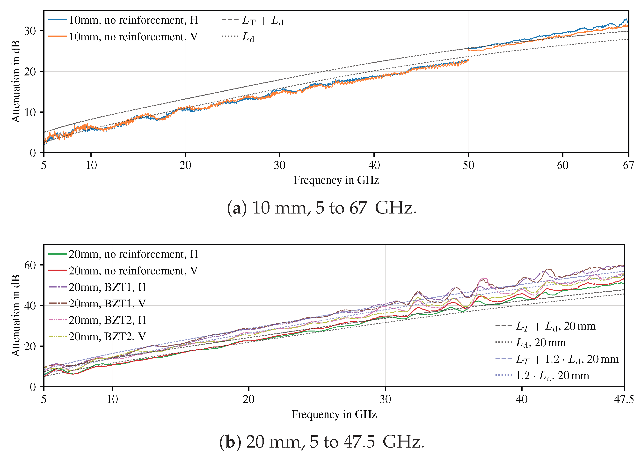
Figure 6a shows the measurement results for all concrete samples from 0.4 to 5 GHz. All samples show an oscillating behavior depending on the sample thickness, which can be explained by internal interference (i.e., the superposition of multiple reflections at the medium boundaries). The samples with carbon fiber reinforcements strongly attenuate the transmitted power up to 2 GHz. The non-reinforced samples do not show this behavior, independent of their thickness. Also, the thicker samples cause a higher attenuation than the thinner ones. The attenuation declines much faster compared to the reinforcement material (see Figure 4), being effectively indiscernible already at about 2 GHz, whereas in Figure 4 the influence is notable up to about 5 GHz. As in Figure 4, the attenuation is dependent on polarization.
In order to explain this behaviour, we turn to the wire screen model [33] again. The wire screen is now embedded in a dielectric. Recalling that the speed of light inside a medium depends on relative permittivity ε r and relative permeability μ r :
c = ε 0 ε r μ 0 μ r 1 / 2 ,
with ε 0 and μ 0 the permittivity and permeability of free space. Inserting into Equation (1), replacing c 0 with c, and setting μ r = 1 (due to the dielectric nature of the medium), yields:
SE dB 20 log 10 2 f g μ 0 ε 0 ε r ( f ) ,
which is the shielding efficiency for a small aperture metal shield, embedded in a dielectric characterized by the frequency-dependent relative permittivity ε r ( f ) .
In Figure 6b the attenuation of the reinforced concrete slabs is shown, together with the predictions from Equation (3) for wire screens with 10.7 mm and 13 mm gap widths (see Table 2), with ε r from the fit curve in Figure 5. As can be seen, the curves follow the predicted attenuations, although the measured attenuations are much higher. This can be attributed to the low thickness of the material and the increasingly low frequencies, so that a frequency-dependent effective permittivity can be assumed:
ε r , eff ( f ) = ε r ( f ) z + ( 1 z ) ,
where 0 z 1 is the fraction of the wavelength that is inside the dielectric. As can be seen, using an effective permittivity based model yields a much better fit, which, most importantly, does not underestimate the losses.

4.4.2. 5 to 67 GHz

Figure 7 shows the loss experienced by the electromagnetic wave traveling through the concrete slabs from 5 to 67 GHz for the 10 mm samples, and 5 to 47.5 GHz for the 20 mm samples. As expected, the attenuation increases with frequency. For the 20 mm samples it increases twice as fast as for the 10 mm samples, due to the double thickness (double y axis range in Figure 7a vs. Figure 7b).
Looking at theory, two mechanisms can explain this behaviour: loss attributed to the tan δ of the material, and loss due to reflections at the material boundaries.
In order to quantify the dielectric loss, we assume a non-magnetic medium μ r = 1 with zero conductivity σ = 0 . The attenuation constant α d due to dielectric losses can be expressed as [37]:
α d ω μ 0 ε ε 2 ε .
Using the relationships
ω = 2 π f , tan δ = ε ε ,
we can restate using frequency-dependent terms:
α d ( f ) = π f tan δ ( f ) ε 0 μ 0 ε r ( f ) .
The dielectric loss L d , in dB , can then be written as follows:
L d , dB = 20 ln 10 x α d ( f ) 8.686 x α d ( f )
with x the material thickness in m . Assuming homogeneous material, it is useful to normalize to a certain thickness for easier comparison. For 1 cm, Equation (7) becomes:
L n , dB / cm = 0.2 ln 10 α d ( f ) 0.08686 α d ( f )
To calculate the losses that occur at the medium’s boundary transitions, Fresnel’s equations (e.g., Reference [38]) can be used. Two transmissions are necessary: from free space into concrete, and from concrete back into free space. Assuming perpendicular incidence, the (double) transmission loss L T is:
L T , dB = 20 log 10 4 ε r ( f ) ε r ( f ) + 1 2 .
Both Figure 7a,b show L d as well as L T + L d , with the values for tan δ ( f ) and ε r ( f ) taken from Figure 5. The measured curves of the 10 mm samples presented in Figure 7a follow the curves as predicted by theory closely. The discontinuity at 50 GHz is caused by the switch-over to the different measurement setup (see Section 3.3). The measured attenuation is a little lower than predicted up to 50 GHz; the other measurement setup yields values a little higher than predicted, always within a 4 dB range. As shown in Figure 7b, the measured data of the unreinforced 20 m m samples also closely follows predictions. Looking at both Figure 7a,b, the attenuation of the un-reinforced samples is stronger than predicted by theory towards higher frequencies. This may be caused by surface roughness, as described above and shown in Figure 2.
For the 20 mm samples shown in Figure 7b, measurement data is only useable up to 47.5 GHz, due to the combined losses of free space path and material. It can be seen that the different samples group: both curves of each BZT 1, BZT 2, and “no reinforcement” are close to one another. The samples without reinforcement show the lowest attenuation, followed by BZT 2 and then BZT 1, each separated by about 4 dB. This is contrary to the expectation that the reinforced and unreinforced samples would group, and reinforcement would have no significant influence. This may be caused by additional internal scattering by the carbon fiber reinforcement. This effect can be captured by a 20% “penalty” to the normalized loss factor L n , also shown in Figure 7b.
Looking again at Figure 7a with Equation (8) in mind, we can see that L d = L n , due to the material thickness being 1 cm. L n is very high, with 5 dB/cm at 10 GHz and 26 dB/cm at 60 GHz. In Reference [17], a measurement of a concrete sample with L n 3.6 dB/cm at 10 GHz is presented. Unfortunately, details about the manufacturing process are not included. The value is in agreement with our measurements, also showing a very high loss of concrete.

5. Conclusions and Further Work

It was demonstrated that the metallic wire screen model can be used to model the RF behavior of the carbon fiber reinforcement. This is discussed in detail below.
Also, thanks to the co-operation between the Chair for RF Engineering and the Institute of Concrete Structures, the materials, production and curing of the concrete samples were documented. Improved documentation improves comparability and reproducibility of the presented results significantly, addressing the issues discussed in Section 2.2.

5.1. Influence of the Reinforcement

Carbon fiber reinforcement material influences the propagation of electromagnetic waves. This is caused by carbon fiber being a good conductor and the spatial arrangement as a rectangular grid, forming a wire screen. The “small aperture metal” wire screen model [33] yields very good predictions. It is therefore recommended to use this model for radio propagation modeling where carbon fiber reinforcement is used in construction.
When embedded in concrete, the influence of this effect is shifted towards lower frequencies, and therefore not as strong as in free space for a given fixed frequency. However, when only considering the permittivity of the concrete as a background medium, the effect is underestimated. As shown in Section 4.2, using a simple effective permittivity model, which considers the material’s thickness with regard to wavelength, yields a fit which avoids underestimation of the incurred losses.

5.2. Characterization of the Investigated Samples

The influence of the investigated reinforcement material samples BZT 1 and BZT 2 is best described as follows: Radio applications in the ISM band around 430 MHz, the frequency band currently used by many building automation applications in Europe, may experience an additional loss of 30 dB and more, depending on polarization, due to the carbon fiber reinforcement. The effect is still present at around 900 MHz (GSM, LTE, DVB-T), with an additional loss of 10 to 20 dB. This may be alleviated by the fact that shielding can never be perfect: When a room is not completely enclosed by the wire mesh shielding, that is, where the carbon fiber reinforcement is not meticulously connected between wall segments (which is unrealistic in practice), the gaps will reduce the shielding efficiency significantly. Beginning at 2.4 GHz (WiFi), the effect is barely noticeable anymore.
Beyond 10 GHz, the dielectric loss of the concrete dominates. The reinforcement material embedded in the investigated samples causes additional losses, which can be modelled by a 20% “penalty” to the normalized loss factor L n (or wall thickness).

5.3. Influence of the Pagel TF10 Fine Concrete

The complex dielectric permittivity of Pagel Pagel TF10 fine concrete was measured from 5 to 67 GHz [34,35]. A fitting procedure was used to derive a parameterized continuous function for the range from 0.1 to 67 GHz. The loss tangent tan δ is between 0.175 and 0.225 over the entire investigated frequency range. The concrete can therefore be described as very lossy, with losses of 5 dB/cm at 10 GHz, rising nearly linear to 27 dB/cm at 60 GHz.

5.4. Consequences for Indoor and Urban Radio Communications Planning

When planning radio communications for buildings with carbon fiber reinforced elements, the reinforcement material’s grid gap widths, fiber diameters, as well as their spatial arrangement, need to be known to the planner.
Also, it should be taken into consideration that the losses caused by wire screens are “reflection losses” by nature [33].
Where radio communication below 2 GHz through walls is a requirement, it might be desirable to include walls or wall segments without reinforcement, or reinforcement made of AR glass or basalt, thereby forming “radio windows”.
Above 10 GHz, the dielectric loss of the concrete is dominating, making radio communication infeasible starting at a material thickness of 10 cm, with L d , 10 GHz = 50 dB. As an example: assuming 30 dB as acceptable loss, the concrete thickness for a maximum frequency of 10 GHz should not exceed 6 cm. Considering the 20% penalty proposed in Section 4.4, this number reduces to 5 cm. Including the loss due to double transmission L T , 10 GHz 3 dB, 6 cm become 5.4 cm, and 5 cm become 4.5 cm. It should be noted that concrete layers that thin are achievable thanks to the novel reinforcement material, so that radio communication can still be achieved. In scenarios where a limitation of the RF range is desirable (for example, multiple small cells instead of a single large cell), thicker walls (in newly constructed buildings) can be used as a cheap way to achieve this goal.

5.5. Further Work

The determination of the electrical properties of concrete is a field deserving further research, as the amount of structures built purely with concrete is expected to grow, especially with new high-performance reinforcement materials. Available literature to this day insufficiently addresses the diversity of concrete, as discussed in Section 2.2. Therefore, it is desirable to derive parameterized models to describe permittivity and losses of the materials, which will be of great use in indoor and urban radio communications planning. These parameters should, at a minimum, be: the filling aggregate’s grain size, and the mixture ratio of filling aggregate, cement and water. Further parameters should be investigated, for example, the influence of chemical or mineral admixtures. Water content of concrete is also an important factor that deserves investigation for frequencies beyond 1 GHz.

Author Contributions

Conceptualization, F.S., D.P.; methodology, S.H., P.S.; software, P.S.; validation, S.H., P.S., M.D., F.S., D.P.; formal analysis, S.H., P.S.; investigation, S.H., P.S., M.D.; resources, F.S., D.P.; data curation, S.H., P.S.; writing–original draft preparation, S.H, P.S., M.D.; writing–review and editing, S.H, F.S., D.P.; visualization, S.H., P.S.; supervision, F.S., D.P.; project administration, F.S., D.P.; funding acquisition, F.S., D.P. All authors have read and agreed to the published version of the manuscript.

Funding

This work is supported by the German Research Foundation (DFG) within the Collaborative Research Center SFB 912—HAEC, and the German Federal Ministry of Education and Research under grant no. 03ZZ0374. Open Access Funding by the Publication Fund of the TU Dresden.

Acknowledgments

We thank Sandra Kranich for permission to use the photograph shown in Figure 1a.

Conflicts of Interest

The authors declare no conflict of interest.

Abbreviations

The following abbreviations are used in this manuscript:
FDTDfinite differences in time domain
FSPLfree-space path loss
MUTmaterial under test
RFradio frequency
SEshielding effectiveness
SBRstyrene-butadiene rubber
UHPCUltra high performance concrete

References

  1. Moore, D. The Roman Panteon: The Triumph of Concrete; University of Guam: Mangilao, Guam, 1995. [Google Scholar]
  2. Scheerer, S.; Schladitz, F.; Curbach, M. Textile Reinforced Concrete–from the idea to a high performance material. In Proceedings of the FERRO-11—11th International Symposium On Ferrocement and 3rd ICTRC International Conference On Textile Reinforced Concrete, Aachen, Germany, 7–10 June 2015. [Google Scholar]
  3. Schumann, A.; Michler, H.; Schladitz, F.; Curbach, M. Parking Slabs Made of Carbon Reinforced Concrete. Struct. Concr. 2018, 19, 647–655. [Google Scholar] [CrossRef]
  4. FCC. FCC Takes Steps to Facilitate Mobile Broadband and next Generation Wireless Technologies in Spectrum above 24 GHz. 2016. Available online: https://apps.fcc.gov/edocs_public/attachmatch/DOC-340301A1.pdf (accessed on 30 April 2020).
  5. Nilson, A.H.; Darwin, D.; Dolan, C.W. Design of Concrete Structures, 5th ed.; McGraw Hill Higher Education: Boston, MA, USA, 2015. [Google Scholar]
  6. Schladitz, F.; Tietze, M.; Lieboldt, M.; Schumann, A.; Patricia, M. Carbon Reinforced Concrete in Construction Practice. In IABSE Conference Kuala Lumpur 2018—Engineering the Developing World; International Association for Bridge and Structural Engineering: Kuala Lumpur, Malaysia, 2018; pp. 348–355. [Google Scholar]
  7. Ezquerra, T.A.; Connor, M.T.; Roy, S.; Kulescza, M.; Fernandes-Nascimento, J.; Baltá-Calleja, F.J. Alternating-Current Electrical Properties of Graphite, Carbon-Black and Carbon-Fiber Polymeric Composites. Compos. Sci. Technol. 2001, 61, 903–909. [Google Scholar] [CrossRef]
  8. MatWeb. MatWeb, Your Source for Materials Information. Available online: http://matweb.com/ (accessed on 30 April 2020).
  9. Haynes, W.M. CRC Handbook of Chemistry and Physics, 97th ed.; CRC Press: Boca Raton, FL, USA, 2016. [Google Scholar]
  10. Kirsten, M.; Freudenberg, C.; Cherif, C. Carbonfasern, der Werkstoff des 21. Jahrhunderts. Beton Und Stahlbetonbau 2015, 110, 8–15. [Google Scholar] [CrossRef]
  11. Helbig, T.; Unterer, K.; Kulas, C.; Rempel, S.; Hegger, J. Fuß- und Radwegbrücke aus Carbonbeton in Albstadt-Ebingen. Beton und Stahlbetonbau 2016, 111, 676–685. [Google Scholar] [CrossRef]
  12. Kranich, S. Building Permit Issued for the Construction of the World’s First Carbon Reinforced Concrete Building (Press Release). 2020. Available online: https://www.bauen-neu-denken.de/wp-content/uploads/2020/03/2020-02-07-PM_Baugenehmigung-EN.pdf (accessed on 30 April 2020).
  13. Ferreira, D.; Cuiñas, I.; Caldeirinha, R.F.S.; Fernandes, T.R. A Review on the Electromagnetic Characterisation of Building Materials at Micro- and Millimetre Wave Frequencies. In Proceedings of the 8th European Conference on Antennas and Propagation (EuCAP 2014), The Hague, The Netherlands, 6–10 April 2014; pp. 145–149. [Google Scholar]
  14. Inomata, M.; Ogawa, T.; Yoshino, S. Material Transmission Loss Modeling for Indoor Propagation Modeling. In Proceedings of the 2014 IEEE 25th Annual International Symposium on Personal, Indoor, and Mobile Radio Communication (PIMRC), Washington, DC, USA, 2–5 September 2014; pp. 722–726. [Google Scholar]
  15. Sandrolini, L.; Reggiani, U.; Ogunsola, A. Modelling the Electrical Properties of Concrete for Shielding Effectiveness Prediction. J. Phys. Appl. Phys. 2007, 40, 5366. [Google Scholar] [CrossRef]
  16. Rudd, R.; Craig, K.; Ganley, M.; Hartless, R. Building Materials and Propagation; Technical Report; Office of Communications (Ofcom): London, UK, 2014; Available online: https://www.ofcom.org.uk/research-anddata/technology/general/building-materials (accessed on 30 April 2020).
  17. Ferreira, D.; Caldeirinha, R.F.S.; Fernandes, T.R.; Cuiñas, I. Hollow Clay Brick Wall Propagation Analysis and Modified Brick Design for Enhanced Wi-Fi Coverage. IEEE Trans. Antennas Propag. 2018, 66, 331–339. [Google Scholar] [CrossRef]
  18. Dalke, R.A.; Holloway, C.L.; McKenna, P.; Johansson, M.; Ali, A.S. Effects of Reinforced Concrete Structures on RF Communications. IEEE Trans. Electromagn. Compat. 2000, 42, 486–496. [Google Scholar] [CrossRef]
  19. Weiping, Q.; Shenggao, D.; Yerong, Z. FDTD Calculation of the Effects of Reinforced Concrete Wall on Short Path Propagation of UWB Pulse. In Proceedings of the 2005 Asia-Pacific Microwave Conference Proceedings, Suzhou, China, 4–7 December 2005; Volume 4. [Google Scholar] [CrossRef]
  20. Choroszuho, A.; Butryło, B. Local Attenuation of Electromagnetic Field Generated by Wireless Communication System inside the Building. Przegląd Elektrotechniczny 2011, 87, 123–126. [Google Scholar]
  21. Taflove, A.; Hagness, S.C. Computational Electrodynamics: The Finite-Difference Time-Domain Method, 3rd ed.; Artech House: Boston, MA, USA, 2005. [Google Scholar]
  22. Hintzen, W. Allgemeine Bauaufsichtliche Zulassung abZ Z-31.10-182: Verstärken von Stahlbetonbauteilen (Methods and Procedures for the Reinforcement of Concrete with Textiles). Allgemeine bauaufsichtliche Zulassung/National Technical Approval, Deutsches Institut für Bautechnik. 2017. Available online: https://www.textilbetonzentrum.de/images/AbZ_Z-3110-182.pdf (accessed on 20 May 2020).
  23. TF10/TUDALIT Fine Concrete Data Sheet (English). Data Sheet; PAGEL Spezialbeton GmbH & Co. KG: Essen, Germany, 2017; Available online: https://www.pagel.com/all/pdf/gb/tf10_gb.pdf (accessed on 30 April 2020).
  24. DIN EN 206-1: Beton: Festlegung, Eigenschaften, Herstellung Und Konformität/Concrete—Specification, Performance, Production and Conformity; Norm/Standard Specification, Deutsches Institut für Normung e.V.: Berlin, Germany, 2017.
  25. DIN EN 998-1: Festlegungen Für Mörtel Im Mauerwerksbau—Teil 1: Putzmörtel/Specification for Mortar for Masonry/Part 1: Rendering and Plastering Mortar; Norm/Standard Specification, Deutsches Institut für Normung e.V.: Berlin, Germany, 2017.
  26. DIN EN 12390-2: Prüfung von Festbeton—Teil 2: Herstellung Und Lagerung von Probekörpern Für Festigkeitsprüfungen/Testing Hardened Concrete—Part 2: Making and Curing Specimens for Strength Tests; Norm/Standard Specification, Deutsches Institut für Normung e.V.: Berlin, Germany, 2017.
  27. HL033 Data Sheet. Data Sheet; Rohde & Schwarz GmbH: Munich, Germany, 2018; Available online: https://cdn.rohde-schwarz.com/pws/dl_downloads/dl_common_library/dl_brochures_and_datasheets/pdf_1/service_support_30/HL033.pdf (accessed on 30 April 2020).
  28. 3164-06 Open Boundary Quad-Ridged Horn Data Sheet. Data Sheet; ETS-Lindgren, ESCO Technologies Inc.: St. Louis, MO, USA, 2018; Available online: http://www.ets-lindgren.com/datasheet/antennas/openboundary-quad-ridged-horn/4003/400303 (accessed on 30 April 2020).
  29. RFspin DRH50 Data Sheet. Data Sheet, RFspin s.r.o. 2017. Available online: https://www.rfspin.cz/en/antennas/measurement-antennas/drh50 (accessed on 30 April 2020).
  30. SAGE Millimeter Inc. SAR-2309-15-S2 Data Sheet. Data Sheet. 2017. Available online: https://sftp.eravant.com/content/datasheets/SAR-2309-15-S2.pdf (accessed on 20 May 2020).
  31. White, D.R.J. EMI Test Methods and Procedures; A Handbook Series on Electromagnetic Interference and Compatibility; Don White Consultants, Inc.: Warrenton, VA, USA, 1974; Volume 2. [Google Scholar]
  32. Balanis, C.A. Antenna Theory: Analysis and Design, 3rd ed.; Wiley-Interscience: Hoboken, NJ, USA, 2005. [Google Scholar]
  33. White, D.R.J. Electromagnetic Shielding Materials and Performance, 2nd ed.; Don White Consultants, Inc.: Gainesville, VA, USA, 1980. [Google Scholar]
  34. Seiler, P.; Hegler, S.; Schladitz, F.; Plettemeier, D. Dielectric Material Characterization for 5G Propagation Modelling. In Proceedings of the 2019 IEEE 2nd 5G World Forum (5GWF), Dresden, Germany, 30 September–2 October 2019; pp. 17–21. [Google Scholar] [CrossRef]
  35. Seiler, P.S. Dielectric Material Characterization up to Terahertz Frequencies Using Planar Transmission Lines. Ph.D. Thesis, Technische Universität Dresden, Dresden, Germany, 2018. Available online: https://nbnresolving.org/urn:nbn:de:bsz:14-qucosa2-339342 (accessed on 30 April 2020).
  36. Böttcher, C.J.F.; Bordewijk, P. Theory of Electric Polarization, Vol II: Dielectrics in Time-Dependent Fields, 2nd ed.; Elsevier Scientific Pub. Co.: Amsterdam, The Netherlands; New York, NY, USA, 1973; Volume 2. [Google Scholar]
  37. Ramo, S.; Whinnery, J.R.; Van Duzer, T. Fields and Waves in Communication Electronics, 3rd ed.; Wiley: New York, NY, USA, 1994. [Google Scholar]
  38. Hecht, E. Optics, 5th ed.; Pearson: Boston, MA, USA, 2016. [Google Scholar]
Figure 1. Carbon fiber reinforcement materials.
Electronics 09 00857 g001
Figure 2. Concrete samples surfaces.
Electronics 09 00857 g002
Figure 3. Measurement setup. (a) Free space; (b) Anechoic chamber; (c) Schematic of the anechoic chamber setup, with distances.
Electronics 09 00857 g003
Figure 4. Attenuation of transmission caused by carbon fiber reinforcement material.
Electronics 09 00857 g004
Figure 5. Dielectric properties of Pagel TF10 fine concrete [34].
Electronics 09 00857 g005
Figure 6. Influence of the carbon fiber reinforcement embedded in concrete. (a) Measured values from 0.4 to 5 GHz; (b) Measured values for samples with reinforcement, and predictions as per theory, 0.4 to 5 GHz.
Electronics 09 00857 g006
Figure 7. Attenuation of transmission caused by different concrete samples.
Electronics 09 00857 g007
Table 1. Mechanical parameter guideline values of reinforcement materials [10].
MaterialTensile Strength (Axial)Young’s ModulusDensity
in k N / m m 2 in k N / m m 2 in g / cm 3
Steel0.3 to 0.62107.9
AR Glass Fiber2.0762.7
Basaltic Fiber4.890 to 1102.6 to 2.8
Carbon Fiber3.0 to 5.0240 to 6001.8
Table 2. Dimensions of the investigated carbon fiber reinforcement material, in m m .
Prototype MaterialBZT 1BZT 2
Center-centerbetween warps812.712.7
distancebetween wefts12.31614 to 16
Carbon Fiberwarps222
diameterwefts111
Gapbetween warps610.710.7
widthbetween wefts11.31513 to 15
Table 3. Properties of the investigated concrete samples.
Number ProducedDimensions (x × y × z) in c m Reinforcement & Positioning
350 × 50 × 1none
350 × 50 × 2none
250 × 50 × 2BZT1, centered along z
250 × 50 × 2BZT2, centered along z
Table 4. Overview of the used antennas. The main lobe points in w direction.
AntennaFrequency RangeDimensions (w × d × h)
R&S HL033 [27]0.08 to 2 GHz1.96 × 1.8 × 0.1 m
ETS Lindgren 3164-06 [28]0.3 to 6 GHz51.4 × 50 × 50 cm
RFspin DRH50 [29]4.5 to 75 GHz56 × 43.6 × 37.7 cm
SAGE SAR-2309-15-S2 [30]45 to 75 GHz61 × 32.4 × 26.4 cm

