1. Introduction
The control of EMI in electronic devices is an increasing issue faced by designers in order to ensure that devices comply with EMC requirements to operate simultaneously without inferring with each other. This fact is due to the trends towards higher component integration, printed circuit board (PCB) size and thickness reduction, and the miniaturization of the device housings. Besides, other factors, such as higher switching frequencies in power converters and communication data rates in digital circuits, could lead to EMI problems [
1,
2]. Consequently, EMC engineering should be handled with the system approach, considering EMC throughout the design process to prevent possible EMI problems that could degrade device performance. Therefore, adopting specific solutions as early as possible in the design stage to meet the EMC requirements is of primary importance to reduce penalties from the standpoint of costs, time-to-market, and performance [
3,
4]. The EMC testing process can reveal that the shielding of a certain cable is needed or may even detect an unexpected EMI source when the designed device is connected to external modules, such as a power supply or to another device to communicate with it. When the cables represent the EMI source, that implies failing the conducted or radiated emissions test, and a widely used technique is applying an EMI suppressor such as a cable ferrite [
4].
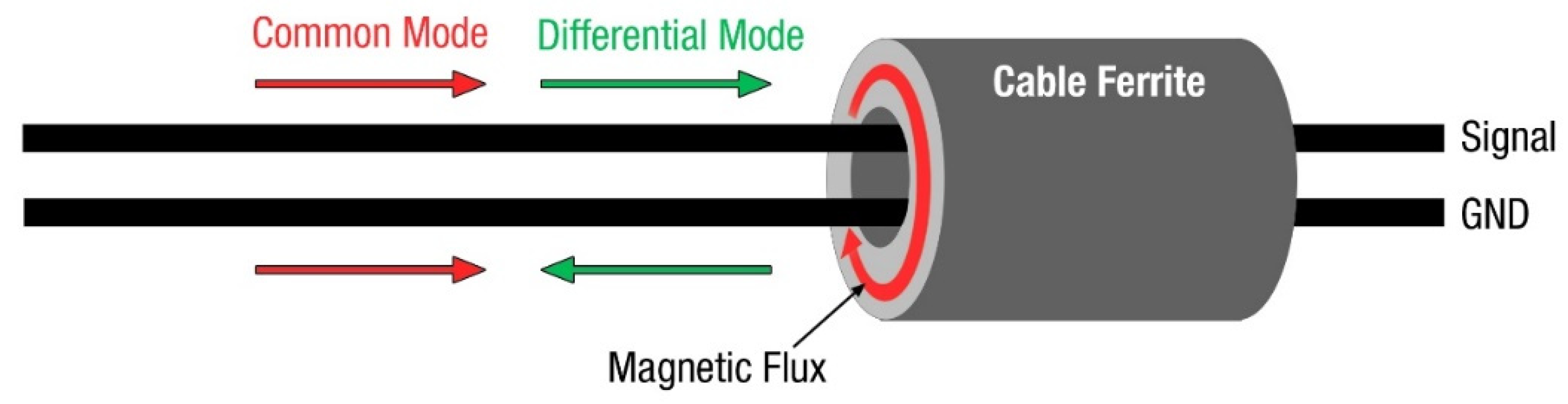
A cable ferrite’s effectiveness to reduce EMI in cables is defined by its capability to increase the flux density of a specific field strength created around a conductor. The presence of noise current in a conductor generates an undesired magnetic field around it that can result in EMI problems. When a cable ferrite is applied in the conductor, the magnetic field is concentrated into magnetic flux inside the cable ferrite because it provides a higher magnetic permeability than air. As a result, the flowing noise current in the conductor is reduced and, thus, the EMI is attenuated. Currents that flow in cables (with two or more conductors) can be divided into differential mode (DM) and common mode (CM) depending on the directions of propagation. Although DM currents are usually significantly higher than CM currents, one of the most common radiated EMI problems is originated by CM currents flowing through the cables of the system [
5]. CM currents, despite not having a high value, have a much greater interfering potential. This fact is because only a few microamps are required to flow through a cable to fail radiated emission requirements [
4]. The use of a cable ferrite is an efficient solution to filter the CM currents in cables because, if a pair of adjacent conductors is considered, when the cable ferrite is placed over both signal and ground wires, the CM noise is reduced. As shown in
Figure 1, the CM currents in both wires flow in the same direction, so the two magnetic fluxes in the cable ferrite are added together, and the filtering action occurs. The intended (DM) current is not affected by the presence of the cable ferrite because the DM current travels in opposite directions and it is transmitted through the signal and returns. Thus, the currents of the two conductors are opposing, meaning they cancel out and the cable ferrite has no effect [
6]. This ability to attenuate only the undesirable CM disturbances is a very interesting feature of this kind of component [
7,
8,
9].
This component represents a solution when the cables turn into an EMI source. It can be applied to peripheral and communication cables such as multiconductor USB or video cables to prevent interferences that could be propagated along the wire, affecting the devices that are interconnected [
10,
11]. This component is also widely used to reduce high-frequency oscillations caused by the increasingly fast switching in power inverters and converters with cables attached without scarifying the switching speed and increasing the power loss. Therefore, selecting the proper cable ferrite makes it possible to reduce the switching noise by increasing the propagation path impedance in the desired frequency range [
5].
The application of cable ferrites is a widely used technique to reduce EMI in cables, despite the drawbacks that the integration of an extra component can involve in terms of cost and production of the system [
12]. Nevertheless, these drawbacks are usually compensated by the effectiveness of cable ferrites to filter interferences without having to redesign the electronic circuit [
6,
7]. Manufacturers provide a wide range of ferrite cores with different shapes, dimensions and compositions, but the most widely used solutions applied to cables are the sleeve (or tube) ferrite cores or their split variation, the openable core clamp (or snap ferrites) [
13]. This component is manufactured from two split parts pressed together by a snap-on mechanism, turning this into a quick, easy to install solution for reducing post-cable assembly EMI problems. The main advantage of snap ferrites compared to solid sleeve ferrite cores is the possibility to add them to the final design, without manufacturing a specific cable that includes the sleeve ferrite core before assembling its connectors.
Nevertheless, the halved ferrite’s performance will be lower than that of a solid core with the same composition and dimensions in terms of the relative permeability (µr) and hence the impedance introduced in the cable [
14]. This performance degradation is caused by the gap introduced between the split parts. Additionally, the presence of a defined air gap between the split parts can turn into an advantage from the standpoint of the core saturation because it allows for higher DC currents before saturation is reached as compared to solid cores. For applications such as power supplies or motor drivers, high DC currents flow through the cable, and the performance of the cable ferrite can be degraded [
8]. Therefore, in these situations, it is interesting to halve the cable ferrite with the aim of introducing a controlled gap that reduces the influence of DC currents into it [
15,
16].
The materials selected to carry out the characterization in terms of cable ferrite performance considering gap and stability to DC currents are two ceramic cores based on MnZn and NiZn and a third core of nanocrystalline (NC) structure. One of the main advantages of MnZn and NiZn materials is the possibility of creating cores with many different shapes and the possibility of halving them without modifying their internal structure [
17,
18]. Preliminary studies have shown that NC sleeve ferrite cores provide a significant effectiveness when used as an EMI suppressor [
17,
19,
20]. Nevertheless, the internal structure and manufacturing process have traditionally made it complicated to obtain a split-core sample that can be used as a snap ferrite, keeping its effectiveness. Therefore, a prototype of a split-core of an NC sample has been manufactured based on a new cutting and assembling technique that makes it possible to analyze this material’s performance when it is halved.
Consequently, one of the main objectives of this contribution is to analyze the dependencies between the gap parameter and the performance in terms of impedance provided by the snap ferrite. This analysis is performed through an experimental measurement setup that is compared with the results obtained through a finite element method (FEM) simulation model. The simulation model helps to determine the study’s accuracy, specifically in the high-frequency range where parasitic elements may affect the experimental results [
20]. Likewise, the stability of three solid (not split) and split cable ferrites based on different compositions are characterized in order to determine the influence of DC currents on the impedance response provided. The results obtained from this study make it possible to compare the different materials to find out which one is the most efficient, depending on the frequency range.
Thereby, the three different materials and their structures are described in
Section 2 through the main magnetic parameters, such as the relative permeability and the reluctance caused by introducing a gap.
Section 3 defines the measurement setups employed to perform the experimental results and the designed FEM simulation model description. Subsequently, in
Section 4, the three different samples’ performance under test is shown in terms of impedance versus frequency. The dependencies on the air gap introduced in the split-cores and the influence on the injection of DC currents are discussed. Finally, the main conclusions are summarized in
Section 5 to determine the performance of each material when used as an openable core clamp.
2. Magnetic Properties
The magnetically soft ferrites are widely used for manufacturing EMI suppressors as cable ferrites. Conventionally, the most used ferrite cores for filtering applications are based on ceramic materials (also known as polycrystalline materials) and, although they do not belong to the metals group, they are made from metal oxides such as ferrite, nickel and zinc. MnZn and NiZn represent two extensively used solutions due to their heat resistance, hardness, and high resistance to pressure. An advantage of ceramic materials is the possibility of manufacturing components with many different shapes and dimensions. The remarkable fact about the ceramic ferrites is that they combine extremely high electrical resistivity with reasonably good magnetic properties [
21]. The starting material is iron oxide Fe
2O
3 that is mixed with one or more divalent transition metals, such as manganese, zinc, nickel, cobalt or magnesium [
14]. The manufacturing procedure can be divided into these steps. First, the base materials are weighed into the desired proportions and wet mixed in ball mills to obtain a uniform distribution and particle size. Next, the water is removed in a filter press, and the ferrite is loosely pressed into blocks and dried. It is then pre-fired (calcined) at about 1000 °C to form the ferrite. The pre-sintered material is then milled to obtain a specific particle size. Subsequently, the dry powder is mixed with an organic binder and lubricants before being shaped by a pressing technique to obtain the final form. Finally, the resultant green core is subjected to a heating and cooling cycle, reaching temperatures higher than 1150 °C, promoting any unreacted oxides to be formed into ferrite. The manufacturing procedure and the material mix are essential to define a ceramic core’s magnetic properties. With MnZn materials, it is possible to obtain samples that provide initial permeabilities of the order of 1000–20,000 and provide a low resistivity (0.1–100 Ω·m). Their range of frequency for EMI suppression applications covers from hundreds of kHz to some MHz.
Regarding NiZn materials, these provide initial permeabilities of the order of 100–2000, so they are intended for a higher frequency operation than MnZn, covering from tens of MHz up to several hundreds of MHz. In terms of resistivity, NiZn materials reach high values (about 10
4–10
6 Ω·m) [
15,
21,
22]. Therefore, considering the structure of ceramic cores, they can be considered as isotropic.
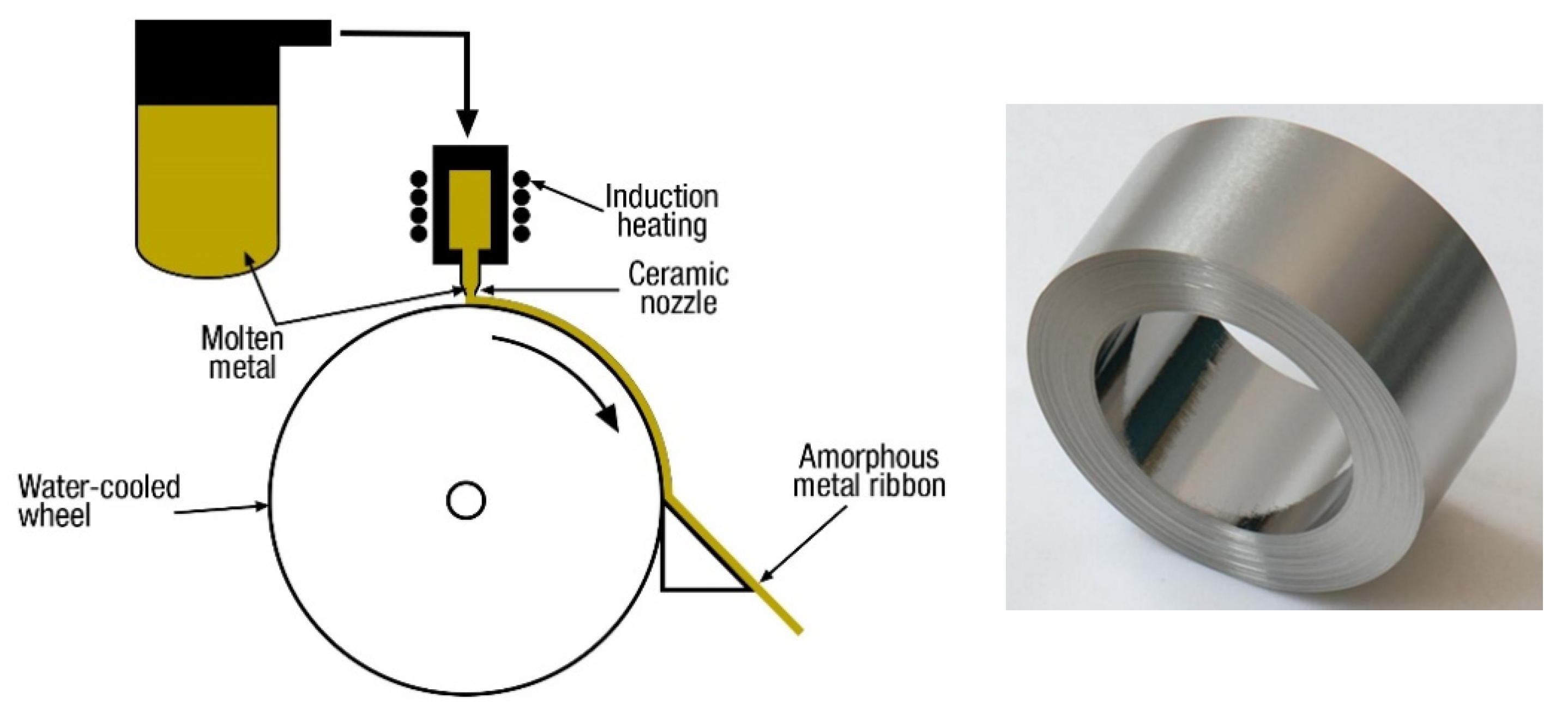
The structure and manufacturing technique used for ceramics make it possible to produce split-cores or cut a solid core after its production with water-cooled diamond tools to build snap ferrites [
14]. The NC cores’ manufacturing procedure is quite different from the one used for ceramic production since they are formed by a continuous laminar structure that is wound to form the final core. The tape-wound structure is based on an amorphous ribbon of only 7–25 micrometers in thickness. It is generated by melting the base material by heating it at 1300 °C and depositing it on a high-speed cooling wheel (100 km/h) that reduces the temperature of the material to 20 °C at a rate of 10
6 K/s. After that, the rolled material is exposed to an annealing process, usually under a transversal and longitudinal magnetic field. This treatment affects the magnetic properties, resulting in ultrafine crystals with a size of the order of 7–20 nm. Finally, an epoxy coating or an additional protective case is needed to protect the sample, due to the brittle nature of the tape. Depending on the parameters selected during the manufacturing procedure, NC samples can provide initial permeability values in the range of 15,000 to 150,000. Electrical resistivity is relatively high even if it is considered a metallic material, generally over 10
−6 Ω·m [
14,
15,
17,
23]. The NC material structure presents the advantage of designing smaller components with more significant magnetic properties for EMI suppression [
19,
20,
24,
25,
26,
27].
Figure 2 shows the NC core before adding the protective coating and its manufacturing procedure diagram.
Ceramic and NC samples can be manufactured as sleeve cores but have a different internal structure. From the point of view of the flux, it travels only in the rolling direction of the amorphous ribbon in the NC core. In ceramics, the flux is distributed uniformly because the material is a single homogeneous unit [
21]. This different structure will result in a different behavior when the core is split into two parts for use as a snap ferrite. In ceramic cores, a performance reduction in terms of relative permeability when they are split is expected. However, we could anticipate that in the case of the NC structure, this decrease would be significant. This fact could be considered because when the NC sample is halved, the wound core is cut, limiting the flux path. Thereby, the halved faces have been plated in order to connect both halved parts with the aim of reducing the gap of the resultant snap core.
Table 1 and
Figure 3 show the dimensions of the samples used to develop characterization. Note that the split samples have the same dimensions as the solid cores.
The solid and split-cores’ behavior based on the three different materials is analyzed in this section through the relative permeability. The permeability of magnetic materials generally depends on the magnetic flux density, DC bias currents, temperature, frequency, and intrinsic material properties [
15,
17]. When an air gap is included in a closed magnetic circuit, the circuit’s total permeability is called the effective relative permeability
µe and this is lower than the permeability of the original solid core without the presence of the air gap. In terms of EMI suppression, reducing the relative permeability in a cable ferrite is generally related to the decrease in its ability to attenuate interferences. However, the presence of an air gap is sometimes desired to increase the DC bias capability of the core or to reduce the permeability to achieve a more predictable and stable response with the aim of shifting the resonance frequency (
fr) to higher values to reduce the effects of dimensional effects [
28,
29].
When the two parts of the split-core are joined, a certain air gap remains between them that results in a magnetic reluctance (
R) increase, since the gap represents an opposition to the magnetic flux (
Φ) normal flow [
15,
30]. As shown in
Figure 4, this effect is analogous to adding a series resistor in an electronic circuit to reduce the magnitude of the current. In
Figure 4,
Rc represents the reluctance of the core,
Rg the reluctance of the gap, Φ the magnetic flux that flows through the magnetic path length of the core (
lc),
lg the length of the air gap,
i the current that flows through the conductor and
N the number of turns.
The general expression to obtain the magnetic reluctance is given by [
15]:
where
l corresponds to the magnetic path length and
A to the cross-sectional area. The
l and
A parameters are obtained from the dimensional features of the sample, considering a toroid with a rectangular cross-section:
where
H is the core’s height and
OD and
ID are the outer and inner diameter, respectively. The overall reluctance of the split-core considering the air gap can be calculated from (1) as the sum of the reluctance core (
Rc) and reluctance air gap (
Rg) [
13,
15]:
thereby, the air gap factor (
Fg) is
and the effective relative permeability of a core with an air gap is [
14,
15,
31]:
Equation (6) represents the most common and simplified model to approximate the effective permeability caused by an air gap since it underestimates the value of
µe because it does not consider the effect of the fringing flux across the air gap [
32]. In the case of toroid cores, to estimate the influence of the air gap introduced when the core is split into two parts,
lg is usually considered to be twice the spacer thickness [
15,
32]. In order to characterize the reduction of the relative permeability caused by an air gap, the three solid (not split) cores of
Table 1 are compared with three split-cores of the same material and dimensions but introducing four different gaps. Thereby, five study cases are carried out for each core material:
Non-split-core: core without a gap.
Split-core g0: both parts of the core are joined without fixing a gap value. In order to differentiate this case with the non-split-core, a gap value of 0.01 mm is considered.
Split-core g1: both parts of the core are joined by fixing a gap value of 0.07 mm.
Split-core g2: both parts of the core are joined by fixing a gap value of 0.14 mm.
Split-core g3: both parts of the core are joined by fixing a gap value of 0.21 mm.
Figure 5 shows the experimental relative permeability measured for each of the three cores included in
Table 1, considering the five different cases in terms of the gap introduced. The experimental traces (solid traces) are compared with the effective relative permeability calculated (dotted traces) by using Equation (6), considering the four gaps defined above. This parameter has been calculated from the experimental relative permeability of the non-split-core sample. These data are expressed through a vector formed by 801 frequency points with their corresponding permeability values. The effective relative permeability of a core with a specific gap is determined by computing these values point by point. Thereby, the air gap factor value
Fg changes throughout the frequency range analyzed. It is possible to observe that both NiZn and MnZn graphs show a similar response between calculated and experimental results. There is a significant match in the low-frequency region, particularly in the NiZn samples, since they provide a lower and more stable permeability than MnZn cores. In the high-frequency region, the calculated effective relative permeability is lower than the experimentally measured one, verifying that Equation (6) provides an underestimation of this. Another difference between NiZn and MnZn traces is observed by comparing the
g0 traces because the initial permeability decreases mostly in MnZn because the original non-split-core yields a higher initial permeability than the NiZn sample. The estimation of
g0 traces was obtained by fixing a gap of 0.01 mm between both split parts in order to simulate the real snap ferrite’s behavior, and the estimated values match with the experimental data [
13]. The NC graph shows a different behavior than the ceramic core since the experimental and calculated permeability only matches in the low-frequency region. Therefore, unlike ceramic cores, it is not possible to estimate with Equation (6) the effective relative permeability of NC in the middle and high-frequency region when used as a snap ferrite due to its different internal structure.
4. Results and Discussion
This section focuses on analyzing the EMI suppression performance of the three described materials when they are split to be employed as snap ferrites. The results obtained from the experimental measurement setup and those provided by the simulation model are compared through each materials’ impedance. This comparison is carried out to verify that the experimental results are not influenced by elements such as stability of the calibration setup in the high-frequency region and undesired high-frequency resonances caused by parasitic elements that could reduce the accuracy of the measurement. As is shown in
Figure 8, the results are organized in three graphs, one per material: NiZn (a), MnZn (b) and NC (c)). These graphs represent the experimental (solid traces) and computed (dotted traces) impedance provided by the cable ferrite, considering the non-split situation and the split cases where the core is separated into two parts.
From the results obtained, the red traces of the graphs show the impedance provided by each non-split sample and it is possible to verify that the simulated and experimental results are a good match and, consequently, the data derived from the experimental setup can be considered in the whole frequency range analyzed. Consequently, a parametric gap sweep was performed in the simulation model by setting the four defined gap situations (
g0,
g1,
g2 and
g3) and keeping the same magnetic properties introduced to the non-split model. As can be observed, there is an excellent agreement between simulated and experimentally obtained results in NiZn and MnZn traces, whereas there is a significant difference in the NC case. This fact correlates with the conclusions obtained from the effective permeability data of the NC sample, shown in
Section 2. Therefore, it is not possible to determine the NC sample’s behavior when it is split and gapped by considering the non-split sample’s magnetic properties. This is because the cut section’s metallization is not able to maintain the high performance of the original NC sample. Then, the NC experimental results are considered to compare its performance with that provided by NiZn and MnZn samples.
Based on the results of three materials, halving the cable ferrite and using it as a snap ferrite (g0 situation) results in a shift of the resonance frequency at which the sample is able to provide the maximum attenuation ratio at the same time that the impedance is reduced. From the standpoint of the equivalent inductance and resistance series circuit of the sleeve core, the fr is produced when the inductive component (XL) turns into negative values and the resistive part (R) reaches the maximum value. Above this frequency value, the sleeve core’s performance is degraded by the parasitic capacitive effect. Therefore, the fr to higher frequencies shift results in extending the frequency range in which the sleeve core is effective to reduce EMI. This effect is lower for the NiZn cable ferrite since the fr is increased from 86.7 MHz to 92.3 MHz, providing 142.9 Ω and 130.7 Ω, respectively. It represents a reduction of 8.5% in terms of impedance and an increase in the resonance frequency of fr = 5.6%. Regarding the results obtained when a gap is introduced, an impedance of Z = 116.3 Ω (34.9% reduction) at fr = 152.2 MHz for the g1 case, Z = 103.3 Ω (27.7% reduction) at fr = 199.0 MHz for the g2 case and Z = 93.0 Ω (27.7% reduction) at fr = 240.6 MHz for the g3 case. In the case of MnZn, it is possible to observe that the impedance traces are significantly modified when the sample is split since the original sample provides a maximum value of Z = 111.7 Ω at fr = 1.4 MHz. The split-core with one part attached to the other (g0 case) provides Z = 55.0 Ω at fr = 6.6 MHz, so the performance of the cable ferrite is reduced by about 50.8%. It is a relevant performance reduction compared to the attenuation ratio reduction of the NiZn sample. For the rest of the MnZn study cases where a higher gap is introduced (g1, g2 and g3), the impedance is mostly reduced (66.1%, 58.0% and 75.6%, respectively), compared to the NiZn results. Regarding the NC results, as described above, the simulated results obtained for the non-split sample match significantly with the experimental ones. Nevertheless, when the core is split, the simulated results overestimate the experimental data since the maximum impedance provided by the not split sample corresponds to 115.0 Ω, whose fr = 45.5 MHz, whereas when it is split with both parts attached as closely as possible, the impedance is reduced by about 82.9%. When a specific gap is introduced (g1, g2 and g3 cases), the attenuation ratio produced is 86–89%.
The NC simulation model magnetic parameters were modified with the objective of obtaining a more realistic approximation response. Thereby, the model was simulated considering three different situations: non-split-core for the original sample, split-core without introducing a gap (
g0) and split-core with the intended gap (
g1,
g2 and
g3). Consequently, the magnetic parameters of the
g0 situation correspond to the effective permeability measured with the split-core with both parts attached. The rest of gapped cases (
g1,
g2 and
g3) were simulated by considering the measured effective permeability of the sample when the gap
g1 is introduced.
Figure 9 shows that the new simulated results match significantly with the experimental traces.
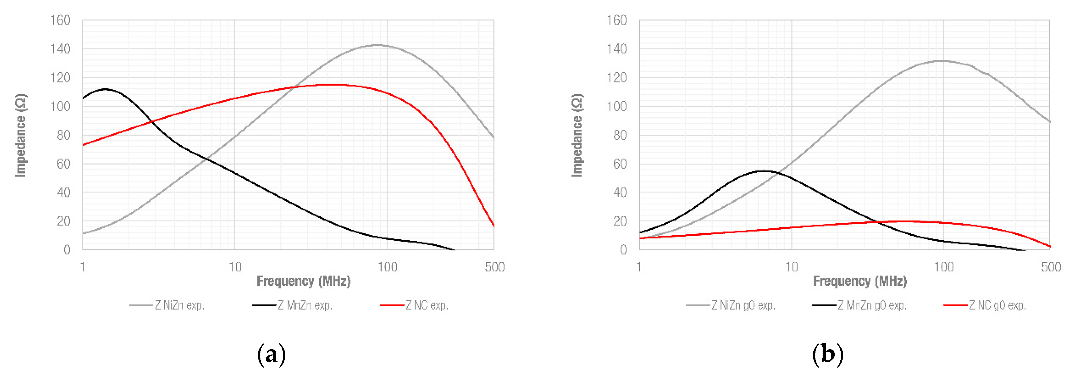
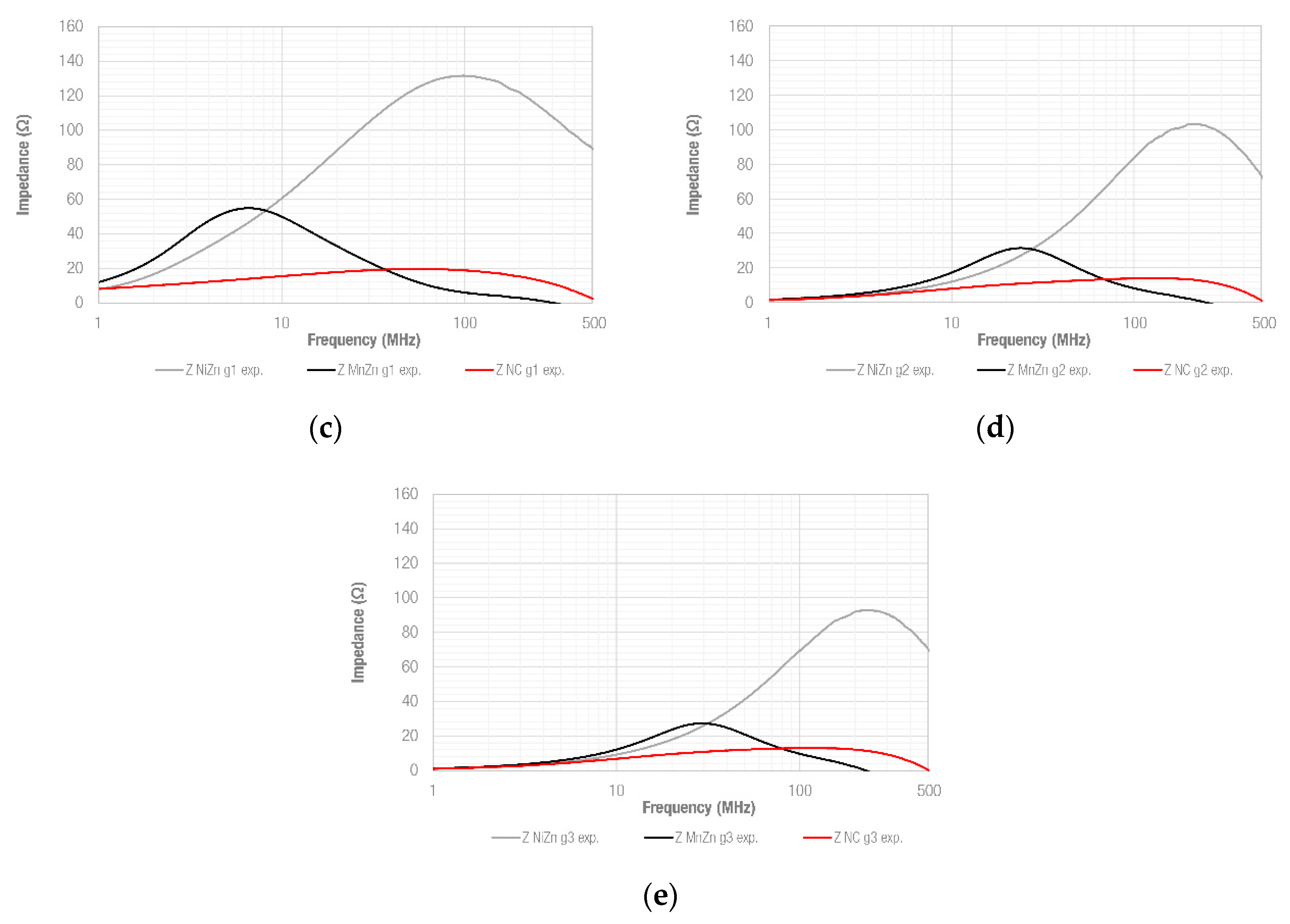
The comparison of the three different cable ferrites by separating them depending on the gap introduced is shown in
Figure 10. As can be observed in
Figure 10a, when cores are not split, they can be divided into three frequency ranges based on their performance. As expected, MnZn provides the larger impedance value in the low-frequency region, yielding the best performance up to 2.9 MHz. The NiZn cable ferrite offers higher impedance than MnZn and NC samples above 23.4 MHz, representing the most effective solution to reduce EMI disturbances in the high-frequency region. The NC core offers excellent performance in the medium-frequency region, providing a great impedance throughout the frequency band from 2.9 MHz to 23.4 MHz.
Additionally, the non-split NC core is able to yield a more stable response up to its maximum impedance value and it shows a better performance than ceramic cores to reduce EMI disturbances when they are distributed in a wideband frequency range (from the low-frequency region up to about 100 MHz).
Figure 10b shows the impedance comparison when the cores are split into two parts and attached as closely as possible, emulating a snap ferrite’s function. In this case, NC has significantly reduced its performance and MnZn provides the best performance up to 8.4 MHz. From this frequency value, NiZn yields the highest impedance value. In the rest of the analyzed gaps (
g1,
g2 and
g3), the NiZn sample mainly represents the most interesting solution because MnZn and NC cable ferrites offer a lower impedance response. Thus, when a significant gap is introduced, the material with lower permeability is able to yield the best EMI attenuation.
How splitting a cable ferrite into two parts, to be employed as a snap ferrite, modifies the impedance behavior was analyzed. Depending on the core’s magnetic properties and structure, this involves a certain degradation of the EMI suppression ability. Nevertheless, splitting a cable ferrite could result in an advantage if the component is intended to encircle cables where DC currents are flowing. To further investigate this effect of the DC currents on the impedance,
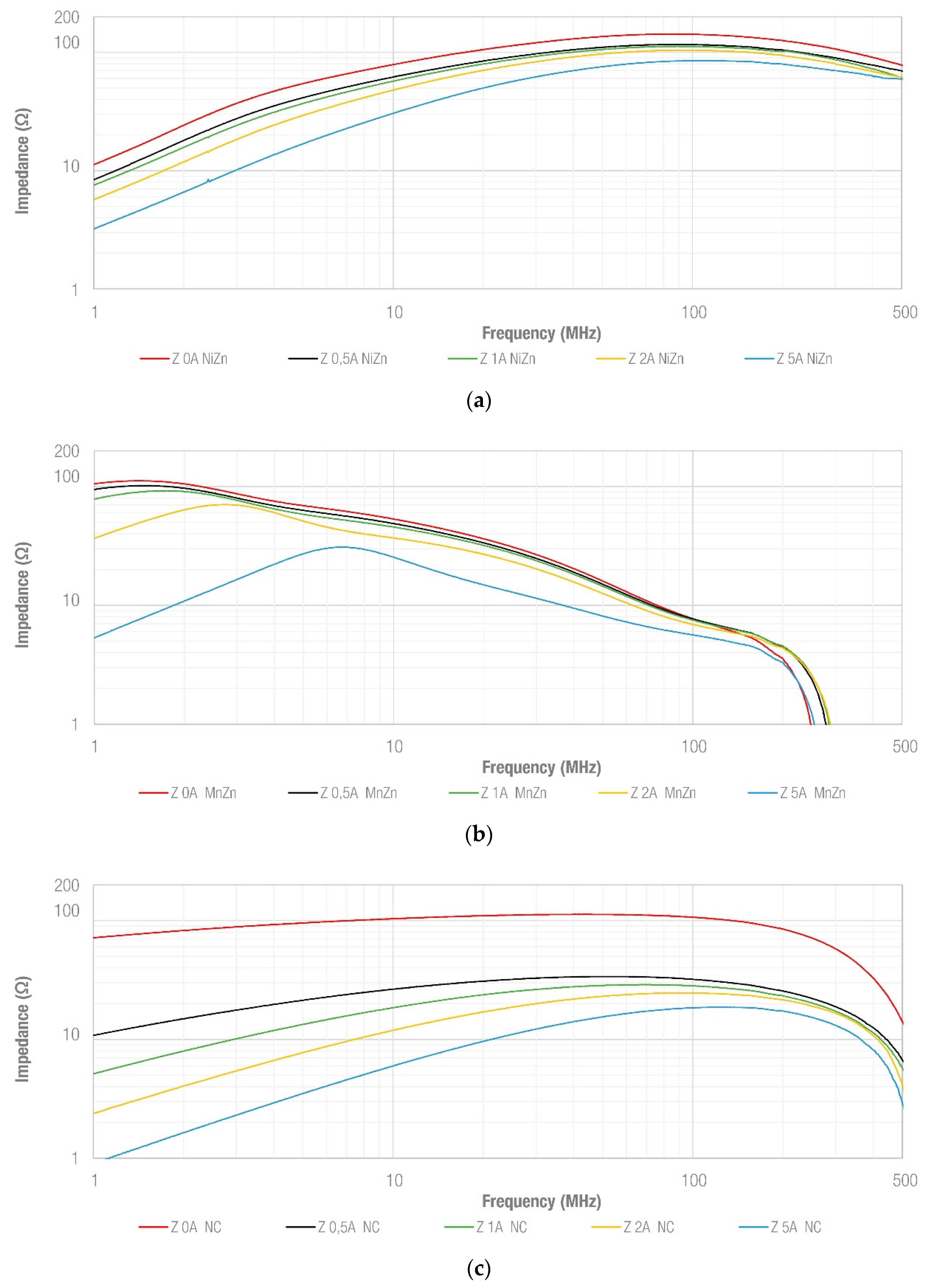
Figure 11 shows the impedance response of each of the three different materials studied when they are under DC bias conditions. Each material is represented in a separate graph and the response of the non-split sample is shown when different values of DC currents are injected (0 A, 0.5 A, 1 A, 2 A and 5 A), as described in
Section 3.
Figure 11a shows that the five traces have a similar trend, but the higher the DC current value, the lower the sample’s impedance. This effect is observed from the lowest DC current value (0.5 A) and does not modify the impedance response significantly when compared to MnZn and NC results (
Figure 11b,c, respectively). It is interesting how the resonance frequency is moved to higher frequencies when an increasing DC current is injected into the MnZn sample, specifically in the cases of 2 A and 5 A. As regards NC behavior, it shows a significant impedance decrease in the low-frequency region and its performance is reduced more than that of ceramic cores when a DC bias flows through the cable.
The same analysis is repeated in
Figure 12 for different gap values introduced in each of the samples. Thereby, the first row corresponds to the split NiZn samples, the second to the split MnZn samples and the third to the split NC samples. The left column shows the behavior of each material when the
g0 gap is considered, and the right column shows the results obtained when
g1 (dotted traces),
g2 (short dashed traces) and
g3 (long dashed traces) gaps are introduced. When the effect on the impedance response of splitting the samples to be attached without an intended gap is observed, the
g0 traces show quite similar behavior in the three materials. NC traces have the same behavior over most of the frequency range, whereas NiZn traces show the same match between traces except for the 5 A case. In the case of MnZn, there is a difference between traces in the low-frequency region, producing a shift of the resonance frequency when DC currents higher than 0.5 A are applied. When the rest of the gaps are analyzed, the three materials have the same response when DC currents up to 5 A are injected. Moreover, from a certain frequency value, the materials’ traces match independently of the DC current value and gap introduced.
5. Conclusions
The performance of the three different materials to build up ferrite cores was evaluated when they are split in order to determine their EMI suppression ability to be used as an openable core clamp. When the samples are not split, the analysis carried out in terms of impedance provided by each sample reveals that a ferrite core based on MnZn yields the best performance in the low-frequency region, whereas an NC core is most effective in the medium-frequency range and the NiZn sample provides larger impedance values in the high-frequency region.
When the samples are split and attached without introducing any gap (g0 situation), the impedance yielded by the NiZn sample is less degraded than the MnZn and NC impedances. In this study case, MnZn provides the best behavior in the low- and medium-frequency range, whereas the NC sample offers lower performance than expected due to its different internal structure. When larger gaps are considered, NiZn shows the most effective solution in terms of impedance. In this framework, other manufacturing procedures for NC snap-on cores should be investigated to obtain similar performance to what this solution can offer when it is not split.
The results obtained from the transmission line simulation model verify that the experimental results are in agreement and, thus, the data derived from the experimental measurement setup can be considered as an accurate approach in the frequency range studied (1–500 MHz). Consequently, the experimental and simulated results coincide with the conclusions obtained from effective relative permeability data. The material with more stable properties can provide higher performance and more predictable behavior than those with greater magnetic properties when the core is split. This conclusion is also applied when DC currents are flowing through the cable to be shielded since the NiZn solution shows better stability than the other materials.

 ,
, 


