Article

A Recent Electronic Control Circuit to a Throttle Device

by
Leonardo Acho
*,
Gisela Pujol-Vázquez
and
José Gibergans-Báguena
Department of Mathematics, Universitat Politècnica de Catalunya (UPC), 08222 Terrassa, Spain
*
Author to whom correspondence should be addressed.
Electronics 2020, 9(1), 191; https://doi.org/10.3390/electronics9010191
Submission received: 1 November 2019 / Revised: 14 January 2020 / Accepted: 15 January 2020 / Published: 19 January 2020
(This article belongs to the Special Issue Sensor-Based Navigation and Control with Applications)

Abstract

:
The main objective of this paper was to conceive a new electronic control circuit to the throttle device. The throttle mechanical actuator is the most important part in an automotive gasoline engine. Among the different control strategies recently reported, an easy to implement control scheme is an open research topic in the analog electronic engineering field. Hence, we propose using the nonlinear dwell switching control theory for an analog electronic control unit, to manipulate an automotive throttle plate. Due to the switching mechanism commuting between a stable and an unstable controllers, the resultant closed-loop system is robust enough to the control objective. This fact is experimentally evidenced. The proposed electronic controller uses operational amplifiers along with an Arduino unit. This unit is just employed to generate the related switching signal that can be replaced by using, for instance, the timer IC555. Thus, this study is a contribution on design and realization of an electronic control circuit to the throttle device.

1. Introduction

There are many engineering systems involving sequence on time switching actions, or a switching-rule, among a finite set of given controllers. Hence, the resultant closed-loop system is a kind of a switched system [1,2,3,4]. Essentially, a switched system may be interpreted as a hybrid dynamical system where the switching-rule mandates the continuous-time subsystem to be activated from a set of stated subsystems. This set of subsystems may contain the resultant closed-loop schemes obtained by invoking a set of granted controllers. Some examples of hybrid systems include: robotics, flexible manufacturing, power conversion, and automotive transmission systems [2,5]. For a historical mathematical review on this topic, see [6] and the references therein. On the other hand, a special case of a switched system consists of both Hurwitz stable and unstable subsystems [1,3]. Therefore, for instance, a linear closed-loop and switched system can be represented by [1,3]:
x ˙ ( t ) = A σ ( t ) x ( t ) , x ( t 0 ) = x 0
where x ( t ) R n is the state of the system; t 0 and x 0 are its initial time and initial state, respectively. The switching signal σ ( t ) : [ t 0 , ) I N = { 1 , 2 , , N } is a piece-wise constant function of time and the switching subsystems A σ ( t ) : [ t 0 , ) { A 1 , A 2 , , A N } . It is assumed that each A i ( i I N ) is a constant matrix of appropriate dimensions, and N > 1 is the number of subsystems to switch. Additionally, a given positive constant τ d , named the dwell time, basically represents the smallest time between consecutive switching commands. Hence, by notation, S [ τ d ] denotes the set of all switching signals satisfying the dwell time τ d restriction. In [3], it is demonstrated that if the number of switching activities are enough big and the total activation time of the unstable subsystems is relatively small with respect to the total activation time of the stable subsystems, then the switched system (Equation (1)) is asymptotically stable under any set S [ τ d ] .
On the other hand, the throttle device is the main mechanical actuator in gasoline engine vehicles [7,8,9,10]. Moreover, this device may emulate other actuator schemes like the pitch mechanism in wind turbines [11]. Moreover, in the last decade, many control techniques to this mechanical device have been proposed. These include: adaptive control, neuronal networks, sliding mode control, control base model, learning PID control design, and design in a discrete-time domain [12,13,14,15,16,17], just to name a few. It is well-known that the throttle device is a non-linear system. Hence, it is difficult to control and capture all its dynamics and strong, nonlinear behavior by just using standard linear control framework.
Therefore, the main objective of this paper was to create a simple electronic circuit design to manipulate the throttle device, based on the dwell time switching control theory. This design is restricted to the analog electronic circuit field. This approach is an option, for instance, for the design declared in [11]. To support our approach, we deliver experimental results too. We used a throttle presented, for instance, in [11].
Finally, the rest of this document is structured as follows. Section 2 exhibits the theoretical account of the dwell time switching control mechanism (previously introduced) to obtain the basic rules to be followed on our control circuit design. Then, the experimental platform description and the related results are shown in Section 3. This includes materials and discussions on the obtained results. Finally, in Section 4, a brief conclusion is written.

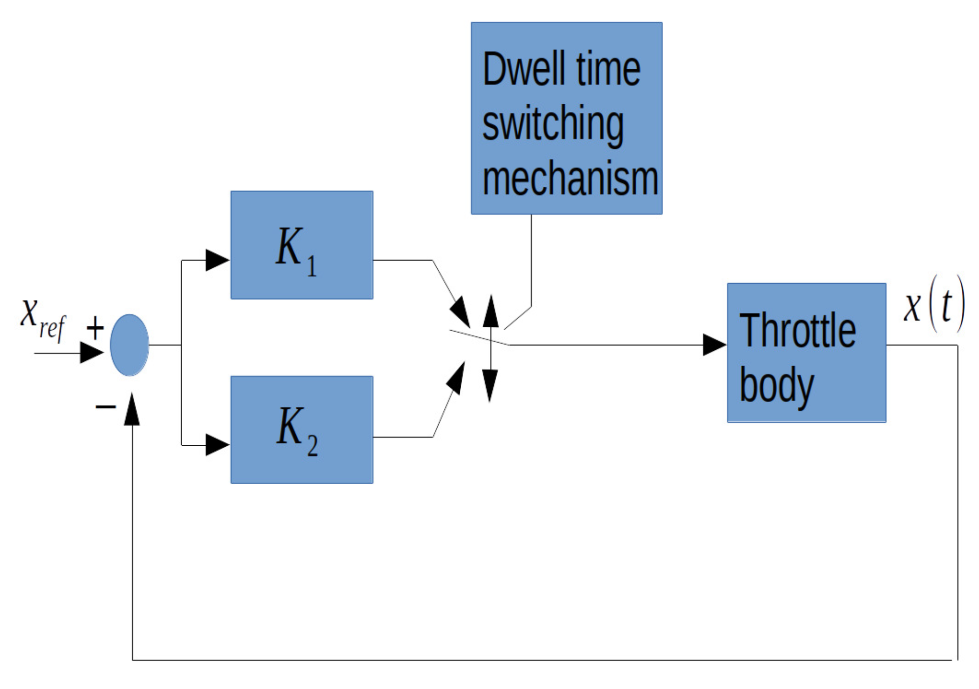
2. Theoretical Framework of the Electronic Control Circuit Design for the Mechanical Throttle System and the Main Control Problem Statement

A throttle device basically consists of a DC motor to drive its throttle plate, a gear box, and a nonlinear restoring spring system. Additionally, it has a throttle plate angular position sensor via a linear potentiometer. Figure 1 shows a photo of the throttle actuator used as described, for instance, in [8,10,11]. Figure 1 gives a schematic point of view of this mechanical body too. Additionally, Figure 2 describes our controller approach. In this figure, two controllers are manifested: u ( t ) = { K 1 e ( t ) , K 2 e ( t ) } , where e ( t ) = x ( t ) x r e f , x ( t ) being the throttle plate angular position and x r e f the reference command signal that may be a piece-wise constant function. According to [11], a simple throttle model for the control design stage can be captured by:
x ¨ ( t ) = a 1 x ˙ ( t ) + a 2 u ( t ) ,
where a 1 and a 2 are constant positive system parameters. This model, obviously, ignores many nonlinear terms of a real throttle device. However, if the controller is enough robust, these non-linearities will be attenuated by the controller itself [11]. For control design, x r e f is assumed constant. Therefore, the closed-loop system is expressed by:
e ¨ ( t ) + a 1 e ˙ ( t ) a 2 u ( t ) = 0 , u ( t ) = { K 1 e ( t ) , K 2 e ( t ) } .
In the above system, we assume that K 1 > 0 and K 2 < 0 are the constant controller gains. These parameters are set such that for K 1 the closed-loop system is unstable and for K 2 is stable in the classical sense of linear control theory. Therefore, the only missing thing is the design of the dwell time switching mechanism such that the closed-loop system be stable (see Figure 2). As it was mentioned in the introduction section, and essentially to our scenario, if the switching number is enough big and the total activation time of the unstable controller is relatively small with respect to the total activation time of the stable controller, then the given closed-loop switched system will be stable under any set S [ τ d ] . See [3]. Hence, a possible switching signal can be described as a pulse-width modulation (PWM) signal; see Figure 3. Therefore, according to the previous statements, there exists a period of this signal with time activation to the unstable controller, T O N , and a time activation for the stable control T O F F satisfying our requirements for stability. By our notation, this T O F F on the unstable controller means the time activation to the stable controller. This kind of signal is in fact a PWM one with a fixed duty cycle. Moreover, and from the electronic point of view, this PWM signal is relatively easy to realize by using, for instance, the well known timer IC555, or by employing an Arduino board, among other options, of course. We decided to employ an Arduino board for its simplicity. Finally, the closed-loop system (Equation (3)) can be stated in the format shown in Equation (1):
d d t e ( t ) e ˙ ( t ) = 0 1 K i a 2 a 1 e ( t ) e ˙ ( t ) , K i { K 1 , K 2 } .
From the above system, it is simple to obtain the related matrix A i ; that is: A i = { A 1 , A 2 } for i = { 1 , 2 } , yielding:
A 1 = 0 1 K 1 a 2 a 1 ,
and
A 2 = 0 1 K 2 a 2 a 1 .

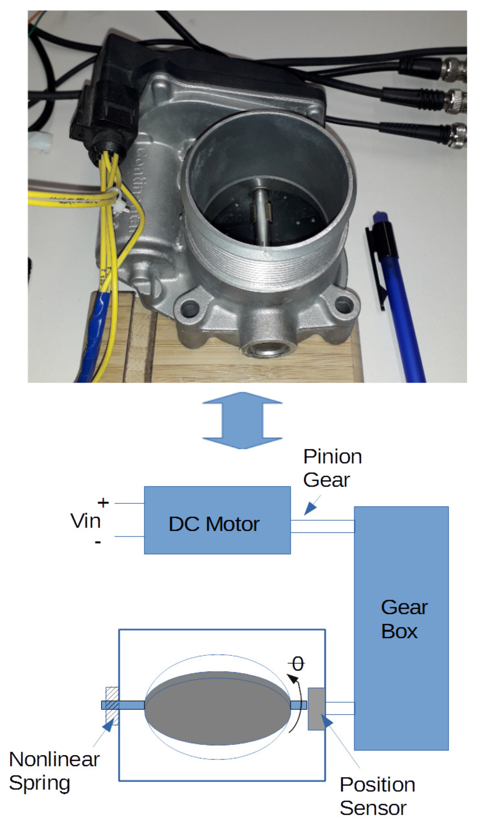
Remarks on the Mathematical Model of the Throttle Mechanism

From the mathematical point of view, the throttle device has a complete non-linear model to primarily capture [18]:
  • The throttle mechanical dynamic friction.
  • The gearbox non-linearity disturbance.
  • The complex return spring torque and non-linear behavior.
In [18], for instance, by using model simplification though bounding some terms, the throttle device model is notoriously simplified. See [19] too. Moreover, linear models of a throttle system have been employed, for instance, in [20]. Hence, the previous evidence motivates to use a linear system model in order to obtain a simple controller able to face the ignored non-linear terms in the control design stage.

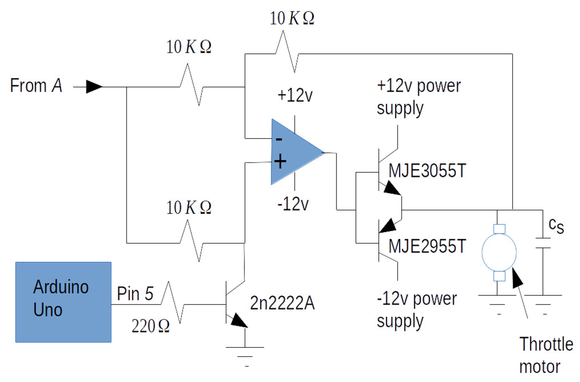
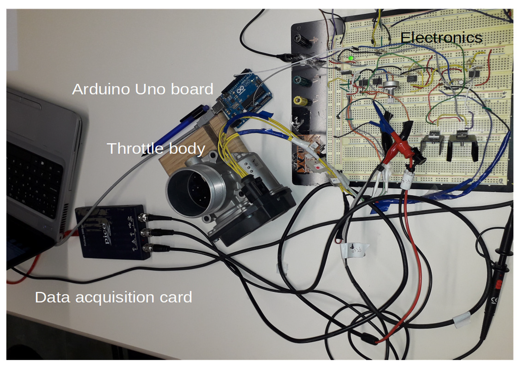
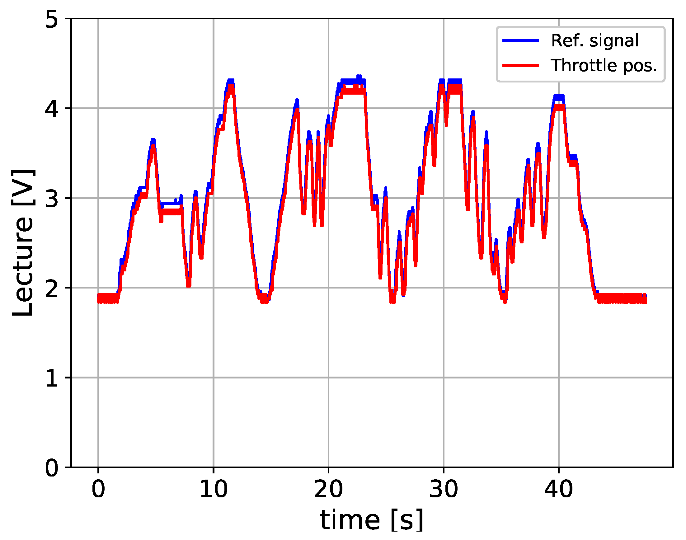
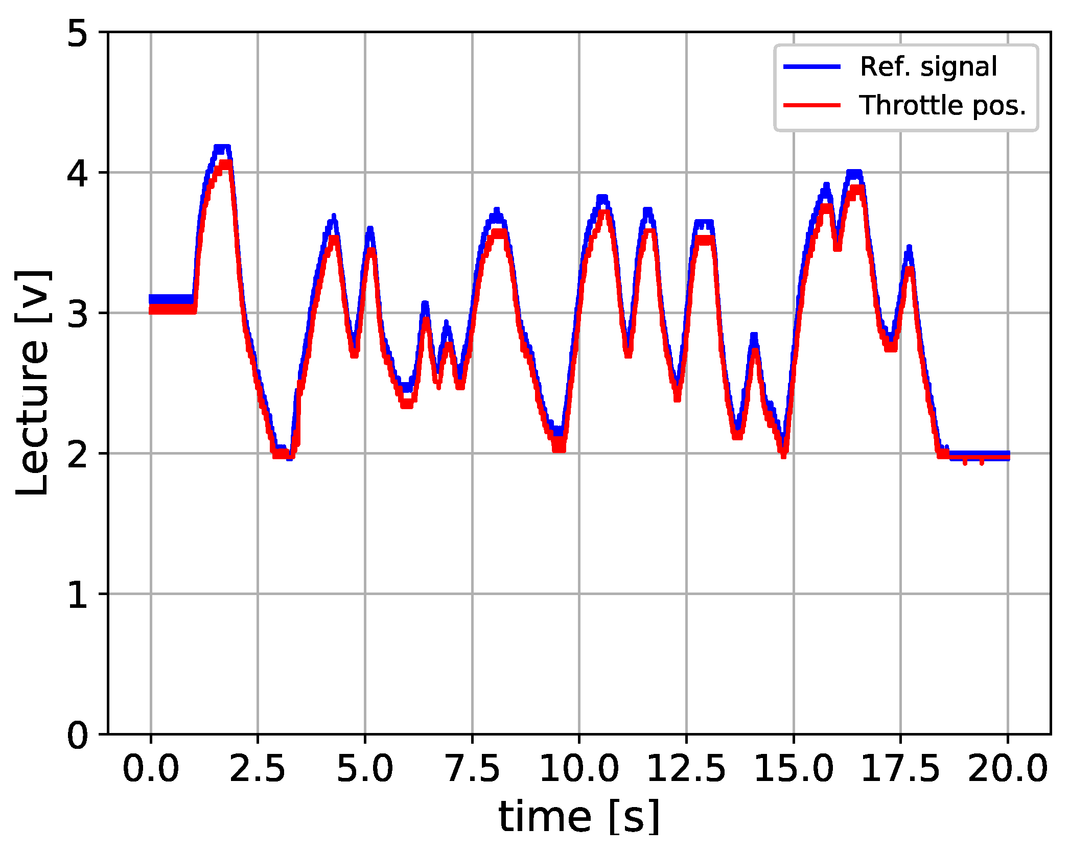
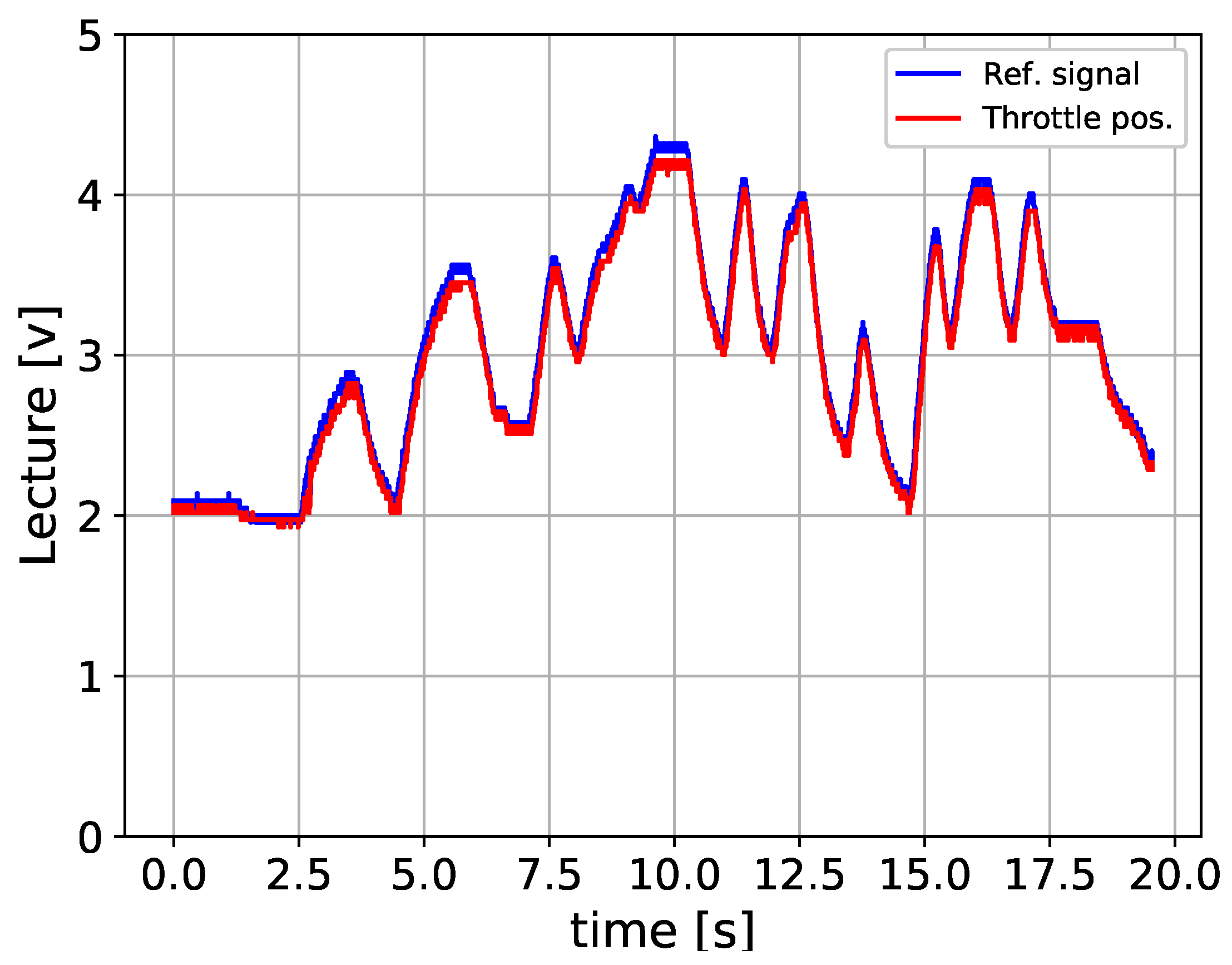
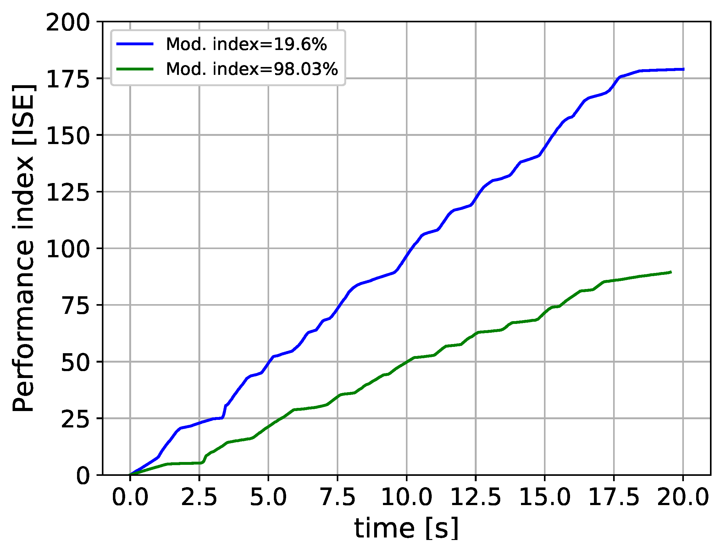
3. Electronic Control Circuit Design, Experimental Results, and Discussions

Our electronic control circuit design is based on the overall schematic system illustrated in Figure 2. Therefore, an analog electronic circuit used to produce the proposed error signal, and then supply it to the switching controller, is shown in Figure 4. This circuit is straightforward to follow. The outgoing signal at A is sent to the circuit illustrated in Figure 5. See Figure 6 too. Once again, in this circuit, we use the L M 741 operational amplifier and C s = 22 pF. What is more, in this experimental development, the related PWM signal was produced by using a modulating index of 86.27% and obtained by invoking the Arduino’s command: analogWrite(5220). Furthermore, the PWM signal supplied by the Arduino Uno at its pin 5 has a base frequency of 976.56 Hz, which is considered high enough for our main intention of controlling the throttle body. In order to satisfy the switching rule previously stated, the duty cycle of this PWM signal was experimentally varied until we noted the desired result. Additionally, Figure 7 and Figure 8 display the experimental outcomes by manually manipulating the pedal emulator potentiometer (blue line) and observing the throttle angle response—shown in red. To recall, from [11], this throttle mechanism has a mechanical angular plate ranging from 14 degrees to almost 90 degrees. Then, the throttle plate angular sensor delivers a linear voltage from 2.0 to 4.6 volts, respectively. In our experiments, we used the PicoScope 2000 Series data acquisition card to evidence the previously cited results. In these figures, the vertical and horizontal scales are clearly marked. The experiments were carried out in a similar fashion to those in [7].
As a comparison issue, and taking into account the experimental throttle design detailed in [7], we can stated the following:
  • Our control approach is well-situated for electronic realization.
  • Our control design does not use a dense data flow algorithm. For instance, in [7], its basic genetic algorithm (GA) requires a fitness calculation and selecting some GA individual objects.
  • Our control structure has fewer control parameters to tune. For instance, in [7], there are 14 parameters to adjust.
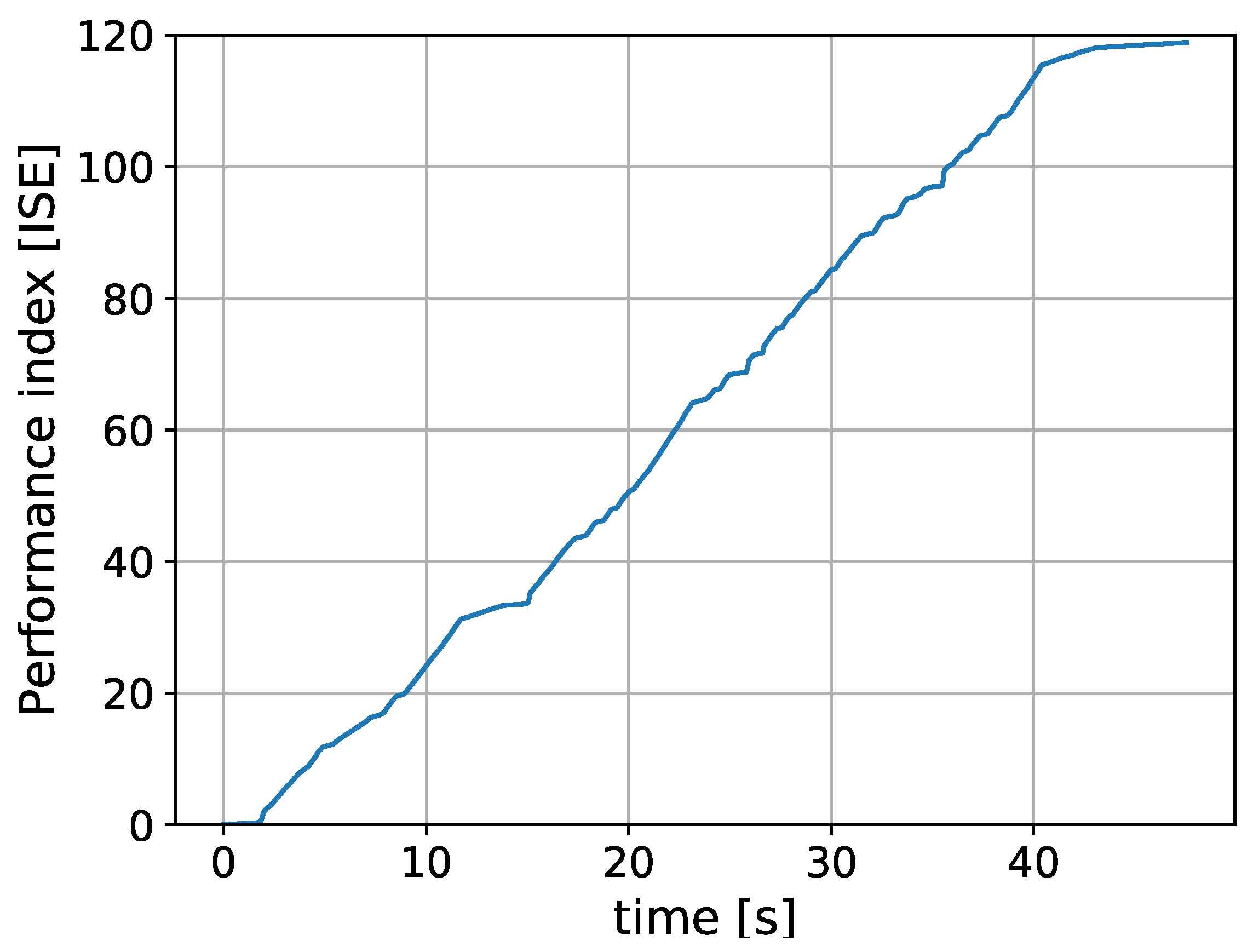
  • In [7], the next performance index on the tracking error during the experiment-time action can be read as:
    J = sup t 0 t T s e ( t ) = 0.05 Rad .
    However, in other experiments realized in [7], this error was about 0.095 Rad. In our case, we have:
    J = sup t 0 t T s e ( t ) = 0.13 Rad .
    The above number could be a disadvantage of our control design. However, a human outer-control loop exists in real automotive control driving to overcome this disadvantage.
To complete our experimental presentation, a video link is located at https://youtu.be/zIo8XtT0gbY. To evidence that our controller’s performance is sensitive to both the base frequency and the PWM duty cycle, Figure 9, Figure 10 and Figure 11 show the observed-data when the PWM base frequency is 7812.50 Hz. Figure 9 corresponds to the case when the modulation index of the PWM is 19.6 %, and Figure 10 for the event of 98.03 %. To recall, the reference command is introduced by manipulating a potentiometer. Hence, this signal is a kind of human-random signal. Table 1 resumes our experimental outcomes. From this Table, we can appreciate that the control performance can be improved by increasing the PWM frequency and by properly manipulating its duty-cycle. Finally, outcomes interesting that, from the experimental results, the tracking error is significantly reduced when the closed-loop system is operated with enough velocity on its reference command. This is also observed in the proposed controllers in [21,22]. Hence, we can arrive to the same conclusion: that the tracking error is reduced if the system is operated with enough velocity.

4. Conclusions

To resume, this paper has proposed the design of a new nonlinear controller for the automotive throttle device by using an analog electronic circuit. This circuit was possible because of the theory employed on the switching dwell time control system. On the other hand, one important key is its cost, which is about 50 euros, including the Arduino Uno unit. Moreover, and from the academic engineering point of view, this electronic circuit would be useful for teaching electronics to the automatic control students, when applied to the challenger control topic, as is the controller of an automotive gasoline engine throttle body.

Author Contributions

The authors contributed equally to this work. All authors have read and agreed to the published version of the manuscript.

Funding

This research was completely funded by the Spanish Ministry of Economy and Competitiveness (State Research Agency of the Spanish Government)/Fondos Europeos de Desarrollo Regional (MINECO/FEDER), grant number DPI2015-64170-R, and also through grant DPI2016-77407-P (MINECO/AEI/FEDER, UE).

Conflicts of Interest

The authors declare no conflict of interest. The funder had no role in the design of the study; in the collection, analyses, or interpretation of data; in the writing of the manuscript, or in the decision to publish the results.

References

  1. Liberzon, D. Switching in Systems and Control; Springer Science & Business Media: New York, NY, USA, 2003. [Google Scholar]
  2. Skafidas, E.; Evans, R.J.; Savkin, A.V.; Petersen, I.R. Stability results for switched controller systems. Automatica 1999, 35, 553–564. [Google Scholar] [CrossRef]
  3. Zhai, G.; Hu, B.; Yasuda, K.; Michel, A.N. Piecewise Lyapunov functions for switched systems with average dwell time. Asian J. Control 2000, 2, 192–197. [Google Scholar] [CrossRef]
  4. Zhai, G.; Li, W.; Huang, C.; Xiao, M. Quadratic Stabilization of Uncertain Switched Affine Systems: An Observer-Based Approach. In Proceedings of the IEEE 2018 57th Annual Conference of the Society of Instrument and Control Engineers of Japan (SICE), Nara, Japan, 11–14 September 2018; pp. 362–367. [Google Scholar]
  5. Li, J.; Pan, K.; Zhang, D.; Su, Q. Robust fault detection and estimation observer design for switched systems. Nonlinear Anal. Hybrid Syst. 2019, 34, 30–42. [Google Scholar] [CrossRef]
  6. Xiong, J.; Sun, Z. An improved combined switching strategy for switched linear systems. In Proceedings of the 2010 IEEE 26-th Convention of Electrical and Electronics Engineers in Israel, Eliat, Israel, 17–20 November 2010; pp. 406–410. [Google Scholar]
  7. Ye, M.; Wang, H. A Robust Adaptive Chattering-free Sliding Mode Control Strategy for Automotive Electronic Throttle System via Genetic Algorithm. IEEE Access 2019, 8, 68–80. [Google Scholar] [CrossRef]
  8. Vargas, A.N.; Menegaz, H.M.; Ishihara, J.Y.; Acho, L. Unscented Kalman filters for estimating the position of an automotive electronic throttle valve. IEEE Trans. Veh. Technol. 2016, 65, 4627–4632. [Google Scholar] [CrossRef]
  9. Vidal Seguí, Y.; Acho Zuppa, L.; Pozo Montero, F. Robust control of an electronic throttle system via switched chattering control: Benchmark experiments. In IFAC Workshop on Engine and Powertrain Control, Simulation and Modeling; IFAC: Paris, France, 2009. [Google Scholar]
  10. Pujol, G.; Vidal, Y.; Acho, L.; Vargas, A.N. Asymmetric modelling and control of an electronic throttle. Int. J. Numer. Model. Electron. Netw. Devices Fields 2016, 29, 192–204. [Google Scholar] [CrossRef]
  11. Acho, L. A proportional plus a hysteretic term control design: a throttle experimental emulation to wind turbines pitch control. Energies 2019, 12, 1961. [Google Scholar] [CrossRef] [Green Version]
  12. Pavković, D.; Deur, J.; Jansz, M.; Perić, N. Adaptive control of automotive electronic throttle. Control. Eng. Pract. 2006, 14, 121–136. [Google Scholar] [CrossRef]
  13. Xiaofang, Y.; Yaonan, W.; Wei, S.; Lianghong, W. RBF networks-based adaptive inverse model control system for electronic throttle. IEEE Trans. Control. Syst. Technol. 2009, 18, 750–756. [Google Scholar] [CrossRef]
  14. Li, Y.; Yang, B.; Zheng, T.; Li, Y.; Cui, M.; Peeta, S. Extended-state-observer-based double-loop integral sliding-mode control of electronic throttle valve. IEEE Trans. Intell. Transp. Syst. 2015, 16, 2501–2510. [Google Scholar] [CrossRef]
  15. Muske, K.R.; Jones, J.C.P.; Franceschi, E. Adaptive analytical model-based control for SI engine air–fuel ratio. IEEE Trans. Control. Syst. Technol. 2008, 16, 763–768. [Google Scholar] [CrossRef]
  16. Sheng, W.; Bao, Y. Fruit fly optimization algorithm based fractional order fuzzy-PID controller for electronic throttle. Nonlinear Dyn. 2013, 73, 611–619. [Google Scholar] [CrossRef]
  17. Honek, M.; Wojnar, S.; Simoncic, P.; Rohar-Hkiv, B. Control of electronic throttle valve position of SI engine. In Proceedings of the International Conference February, Vyšná Boca, Slovak, 10–13 February 2010; Volume 10, p. 13. [Google Scholar]
  18. Jiao, X.; Zhang, J.; Shen, T. An adaptive servo control strategy for automotive electronic throttle and experimental validation. IEEE Trans. Ind. Electron. 2014, 61, 6275–6284. [Google Scholar] [CrossRef]
  19. Hu, Y.; Wang, H. Robust tracking control for vehicle electronic throttle using adaptive dynamic sliding mode and extended state observer. Mech. Syst. Signal Process. 2020, 135, 106375. [Google Scholar] [CrossRef]
  20. Baotic, M.; Vasak, M.; Morari, M.; Peric, N. Hybrid system theory based optimal control of an electronic throttle. In Proceedings of the 2003 IEEE American Control Conference, Denver, CO, USA, 4–6 June 2003; Volume 6, pp. 5209–5214. [Google Scholar]
  21. Guerra, R.; Acho, L.; Aguilar, L. Adaptive friction compensation for mechanisms: A new perspective. Int. J. Robot. Autom. 2007, 22, 155–159. [Google Scholar] [CrossRef]
  22. Guerra, R.; Acho, L. Adaptive friction compensation for tracking control of mechanisms. Asian J. Control 2007, 9, 422–425. [Google Scholar] [CrossRef]
Figure 1. Top: A photo of our throttle device. Bottom: A throttle actuator diagram. V i n would be the control signal u ( t ) .
Electronics 09 00191 g001
Figure 2. The proposed closed-loop control system.
Electronics 09 00191 g002
Figure 3. A dwell-switching signal which can be viewed as a pulse-width modulation (PWM) indicator.
Electronics 09 00191 g003
Figure 4. Analog electronic circuit: the error signal processing unit. Its response is then sent to the circuit in Figure 5. The operational amplifiers employed are inside the L M 741 integrated circuit. Therefore, we obtain e ( t ) = V A = 33 x ( t ) x r e f .
Electronics 09 00191 g004
Figure 5. The electronic circuit to the switching mechanism unit. It receives information from the circuit in Figure 4. From this diagram, { K 1 , K 2 } = { 3.3 , 3.3 } . The operational amplifiers employed are in the L M 741 integrated circuit too. From this circuit, the 2 n 2222 A npn-transistor is employed to switch between the inverting and non-inverting op-amp actions.
Electronics 09 00191 g005
Figure 6. A photograph of the overall experimental platform.
Electronics 09 00191 g006
Figure 7. The throttle valve position follows the reference signal induced by the pedal emulator potentiometer.
Electronics 09 00191 g007
Figure 8. The ISE performance index obtained from the data in Figure 7.
Electronics 09 00191 g008
Figure 9. The throttle valve position following the reference signal induced by the pedal emulator potentiometer.
Electronics 09 00191 g009
Figure 10. The throttle valve position follows the reference signal induced by the pedal emulator potentiometer.
Electronics 09 00191 g010
Figure 11. The ISE performance indexes incurred from the data in Figure 9 and Figure 10, respectively.
Electronics 09 00191 g011
Table 1. The remainder of the experimental results.
PWM Frequency [Hz]PWM Duty Cycle [%]ISE max
976.5686.27119.5
7812.5019.6178.6
7812.5098.0388.8

