Article

Analysis of the Critical Bits of a RISC-V Processor Implemented in an SRAM-Based FPGA for Space Applications

by
Luis Alberto Aranda
1,*,
Nils-Johan Wessman
2,
Lucana Santos
3,
Alfonso Sánchez-Macián
1,
Jan Andersson
2,
Roland Weigand
3 and
Juan Antonio Maestro
1
1
ARIES Research Center, Universidad Antonio de Nebrija, Pirineos 55, 28040 Madrid, Spain
2
Cobham Gaisler, Kungsgatan 12, SE-411 91 Göteborg, Sweden
3
European Space Agency, Keplerlaan 1, P.O. Box 299, 2220AG Noordwjik ZH, The Netherlands
*
Author to whom correspondence should be addressed.
Electronics 2020, 9(1), 175; https://doi.org/10.3390/electronics9010175
Submission received: 13 December 2019 / Revised: 9 January 2020 / Accepted: 13 January 2020 / Published: 17 January 2020

Abstract

:
One of the traditional issues in space missions is the reliability of the electronic components on board spacecraft. There are numerous techniques to deal with this, from shielding and rad-hard fabrication to ad-hoc fault-tolerant designs. Although many of these solutions have been extensively studied, the recent utilization of FPGAs as the target architecture for many electronic components has opened new possibilities, partly due to the distinct nature of these devices. In this study, we performed fault injection experiments to determine if a RISC-V soft processor implemented in an FPGA could be used as an onboard computer for space applications, and how the specific nature of FPGAs needs to be tackled differently from how ASICs have been traditionally handled. In particular, in this paper, the classic definition of the cross-section is revisited, putting into perspective the importance of the so-called “critical bits” in an FPGA design.

1. Introduction

Reliability has always been a concern for space missions, especially for on-board electronics. Since the beginning of the space exploration era, different phenomena affecting the behavior of the electronic components have been reported. This problem is inherent to the harsh nature of space where radiation sources are abundant and heterogeneous [1]. The sources of this radiation may be classified into three categories [2]. First, a range of protons and heavy ions that compose the so-called cosmic rays, whose source is located outside the solar system. These usually present a high energy profile, but with a continuous low intensity. Second, the radiation trapped in the Earth’s magnetic field, with high presence areas as the ones formed by the Van Allen’s belts. This type of radiation is primarily composed of high energy particles as protons and electrons. Third, the most variable source of radiation, which is the one produced by the sun. Solar radiation is a mix of protons, ions, neutrons, gamma rays, etc., and is usually event-driven. This sometimes produces the accumulation of high flux peaks within short periods, having an important effect on the electronics on board spacecraft.
The effects of radiation on these devices are diverse. It may produce damage in the device structure that leads to permanent errors, thus shortening the service life of the system. Conversely, it can produce temporary errors that induce failures until the system is reset [3], or even corruption of the data stored in the memories. Radiation effects have been traditionally mitigated by implementing some kind of protection technique. These techniques cover a wide range of strategies. For example, physically shielding the devices to deflect radiation or fabricate them with so-called rad-hard processes are some alternatives. This type of approach usually implies hefty overheads in terms of cost, area, performance, and power consumption. Another approach consists in protecting the circuits utilizing design techniques, usually adding redundancy [4]. In this case, techniques range from classic schemes such as dual modular redundancy (DMR) or triple modular redundancy (TMR) to ad-hoc techniques that use behavioral or structural properties of the circuits to protect.
In any case, the effects of radiation and the most appropriate technique to deal with them strongly depend on the architecture of the circuit. Traditionally, manufacturing an application-specific integrated circuit (ASIC) has been the most usual way of implementing electronic circuits, since they used to provide the best possible performance and power consumption. Errors produced by radiation on ASICs usually come in the shape of bit flips induced in the storage elements or by transients that propagate through the circuit, which can eventually be registered by a storage element. In both cases, errors can be modeled as propagation of logic values through combinational and/or sequential nets [5]. However, in recent times, field-programmable gate arrays (FPGAs) are steadily becoming the predominant architecture to implement digital circuits in space applications, especially those related to low-cost missions, such as small satellites. The advantage of FPGAs is that they offer a reduced cost, together with high flexibility in terms of reconfiguration capability. Besides, the performance of FPGAs has improved enormously, being appropriate for most kinds of applications. However, SRAM-based FPGA architectures (hereinafter referred to as FPGAs) are quite different from the ASIC ones. In these FPGAs, although the user logic is still vulnerable to radiation, the configuration memory is also vulnerable, and may sometimes be the predominant source of errors, mainly due to its size [6]. If this happens, the effects usually translate into an actual modification of the circuit structure (e.g., a change on the routing or the logic function). This greatly differs from the ASIC case since in FPGAs the error situations are more a structural modification (that requires reconfiguration to be solved), and not a pure error propagation issue. This difference in the error model is the reason there is an increasing trend to study the reliability issues of utilizing an FPGA to host not only payload and instrument-related electronics, but also mission-critical systems such as the onboard computer of the satellite. In this context, the present paper summarizes the work developed in the European Space Agency (ESA) project “Introduction of fault-tolerant concepts for RISC-V in space applications”, conducted by Cobham Gaisler AB and the ARIES Research Center at Universidad Nebrija. The main scope of the project has been to study the reliability of a soft processor implemented in an FPGA, and whether it could replace a traditional ASIC-based processor in space applications. The processor selected for the experiments has been the Rocket RISC-V processor designed at UC Berkeley [7], while the target FPGA has been a last generation Xilinx Kintex UltraScale. The Rocket RISC-V processor was chosen because it is freely available to academia and industry, it was already successfully integrated into other platforms, and there is a hardware/software collaborative ecosystem created around it.
This paper is structured as follows. Section 2 introduces some concepts about the FPGA error model for a better understanding of the rest of the paper. In Section 3, the justification of the analysis performed in this paper is explained in detail. The experimental set-up and the reliability results are presented in Section 4 and Section 5, respectively. Finally, Section 6 concludes the paper.

2. Configuration Memory Errors in SRAM-Based FPGAs

In this section, a brief introduction to the FPGA error model is first presented in Section 2.1 to understand the effects of single-event upsets (SEUs) in the configuration memory of an SRAM-based FPGA. Then, the constraints that have to be faced in the fault tolerance characterization of a design implemented in an SRAM-based FPGA are presented in Section 2.2.

2.1. FPGA Error Model

As stated above, one of the main differences (from the reliability point of view) between a physical ASIC processor and a soft processor implemented in an FPGA is the error model. The former usually suffers bit flips caused by radiation, and the problem resides in tracing their propagation and whether they are masked by the logic or registered by a storage element. This has been studied numerous times in the literature (e.g., [8,9]). However, studying the effects of bit upsets is much more challenging for the FPGA case. While the user logic still suffers from errors, additional problems come from bit flips in the configuration memory, which can produce changes in the structure and the routing of the circuit.
Any design implemented in an FPGA is mainly created by interconnecting some of the configurable logic blocks (CLBs) available in the device and by configuring the CLBs themselves. These CLBs, as well as the routing interconnections, are related to a certain amount of configuration memory bits. In the case of the CLBs, the configuration bits describe their internal components in use, the content of the look-up tables (LUTs), or the operating mode of the mentioned LUTs (e.g., a LUT can be configured as distributed RAM). In this context, SEUs can alter the logic functions defined in the LUTs or the behavior of the LUT itself by affecting these configuration memory bits. On the other hand, the configuration bits associated with the routing define the status of the paths that connect the different resources of the FPGA. Thus, in this case, the following effects classified in [10] may occur:
  • Open fault: The affected bit interrupts a path creating an unconnected signal.
  • Conflict fault: Two signals are connected together creating a short-circuit and, therefore, an undefined output value.
  • Antenna fault: The input path is connected to a floating line segment, thus delivering an unknown value to the output.
  • Bridge fault: The selection bit of a multiplexer is affected by the SEU connecting a wrong input with the output.
These different effects make difficult to predict a specific behavior, which is even more complex in the case of a soft processor. These phenomena are the reason defining a correct methodology to characterize designs in terms of fault tolerance is important when using FPGAs in space applications.

2.2. Characterization of Designs and Fault Tolerance Verification

When trying to assess the fault tolerance of a design implemented in an SRAM-based FPGA, there is usually no public information on what resources are affected by which particular bits of the configuration memory. There are indeed projects devoted to overcoming this issue by documenting the bitstream composition (e.g., Project X-Ray [11]), but this valuable information does not cover every possible FPGA architecture. Moreover, manufacturers such as Xilinx do not usually publish it, thus creating confusion when studying reliability at the register-transfer level. Then, when trying to characterize a circuit and verify its fault tolerance capacity, two alternatives are usually followed. The first one is to actually irradiate it (which usually implies a high cost), and the second one is to induce bit flips in the configuration memory through emulation using one of the many fault injection tools that perform this task (e.g., [12,13]). The simplest approach, in this case, would be to inject errors in all the bits of the configuration memory and check how the circuit behaves. Unfortunately, this is unfeasible most of the time, since the number of such bits is enormous. Another option is to perform a statistical injection process, instead of an exhaustive one, but even with this, a large amount of time is wasted injecting in bits that are not actually used to implement the circuit, thus creating extremely long test campaigns. To solve this problem, most reliability tests are oriented to inject only on what Xilinx calls “essential bits” [14], which are those bits that are actually used to implement the design under test (DUT). Those bits are usually known by the designers, also having several tools to deal with them and restrict them in such a way that a specific part of the circuit can be selected to pinpoint injections, e.g., to inject only in the ALU of a processor, and not in the rest of it. Our group has designed one of such tools, called ACME [15], which is the one used in the present project to study the reliability of the RISC-V processor. With this, it may seem that all the problems are solved: the area of the circuit where the injections are going to be performed is selected, the fault injection campaign is done, and, finally, some statistic of the behavior of the circuit is obtained. In such a scenario, it could be expected that, testing an unprotected circuit, nearly 100% of the affected essential bits would produce an actual structural modification of the circuit, thus leading to wrong behavior. If not 100% (some errors could affect parts of the circuit not being exercised in the test), at least a large percentage, if the test coverage of the design has been done correctly. However, after conducting the experiments of this project, it was observed that the majority of the bit flips (around 90%, see Section 5 for detailed results) were not producing any error at the output of an unprotected RISC-V.
With this in mind, we should think about what this means from the point of view of the “cross-section”, which is one of the basic concepts when studying reliability. The cross-section basically determines the percentage of the particle impacts induced by radiation (formally referred to as “events”) that actually produce a bit flip. This, of course, depends on the typology and intensity of the radiation, the characteristics of the technology (geometries, voltage levels, fabrication process, etc.), and the area of the circuit. It is intuitive to understand that circuits with larger areas will be more exposed to radiation, and therefore will likely suffer a larger number of events. In ASICs, this concept is quite straightforward, being related to the actual area that the circuit occupies. However, the equivalent of the ASIC area in an FPGA is more complex to determine. The simplest approach should be to consider the configuration memory area, but, again, only the area of the bits that are actually being used when implementing the DUT. Perhaps the number of essential bits should be the figure of merit for the cross-section but, as stated above, the results obtained are not coherent with this approach. Although these bits are called “essential”, the name does not necessarily imply that any bit flip in these bits will produce actual structural modifications in the circuit. For example, there may be LUTs in the design that are not 100% used but, since these LUTs are still part of the design, their configuration bits are classified as essential. Therefore, a bit flip in one of those unused bits would produce no modification in the design. In essence, only a fraction of the essential bits can actually jeopardize the reliability of the system, and those are called the “critical” bits. These bits could effectively represent the figure of merit for the cross-section.

3. Proposed Analysis

As explained in the previous section, there is no easy way to obtain the list of the critical bits of a design that could be used, for example, to adjust the protection technique (e.g., scrubbing period) for the configuration memory of the FPGA. The Xilinx Vivado tool does not provide them, just the list of the essential bits. Therefore, from the point of view of reliability, it would be important to have a way to determine them and use this information to properly assess the reliability of the DUT. To achieve this, we have put in place the following procedure:
  • The unprotected design is characterized. We implement the unprotected design (RISC-V in this case), and, using the ACME tool [15], together with the Xilinx SEM IP Controller [16], we perform an injection campaign in the essential bits of the configuration memory while running some benchmarks (see Section 4 for more details). After each injection, the behavior of the design is observed and compared with the golden outcome (the result that should be produced in the absence of error). With this, we obtain how many bit flips have actually produced a failure and how many have not. The purpose of this is to use the unprotected design to “calibrate” the critical vs. essential bit ratio, assuming that, for an unprotected design, nearly 100% of the critical bits should produce an issue.
  • Then, the protected design needs to be characterized. In this work, we have protected a Rocket RISC-V processor with distributed triple modular redundancy (DTMR) for the sake of simplicity, but any other technique can be used. Using the ACME tool, together with the SEM IP, an error injection campaign is performed in all the essential bits, and, again, the number of errors and no errors at the output are logged. The number of errors divided by the total number of injections would give the probability of error of the technique. However, as mentioned above, many of the injections are performed on non-critical bits that would not produce any error whatsoever. That is why the probability of error needs to be normalized, using the critical vs. essential bit ratio calculated in the previous step.
  • Now, the number of critical bits of the DTMR-protected design ( C b p r o t e c t e d ) is normalized as the number of essential bits that are provided by the design tool ( E b p r o t e c t e d ), multiplied by the fraction obtained in the first step (percentage of critical bits ( C b u n p r o t e c t e d ) within the total number of essential bits ( E b u n p r o t e c t e d )). That number of critical bits is what we consider a figure of merit of the cross-section of the protected circuit and is presented in Equation (1).
    C b p r o t e c t e d = E b p r o t e c t e d · C b u n p r o t e c t e d E b u n p r o t e c t e d
    In this same way, the probability of error (P) can be also normalized ( P ¯ ) by dividing this value (calculated in Step 2) by the critical vs. essential bit ratio calculated in Step 1 (the lower the result, the more reliability the protected design offers) as shown in Equation (2).
    P ¯ = P C b u n p r o t e c t e d · E b u n p r o t e c t e d
Notice the importance of the last step. If we measure the behavior of a protected circuit and we determine that, e.g., 99% of error injections do not produce an error at the output, this may mean that the circuit provides a reliability of 99%. However, this may also mean that part of those injections are not producing any error, as proved with the case of the unprotected design. Therefore, it is important to isolate the effect of the non-critical essential bits, so that the results are not biased towards higher reliability than the protected design actually provides.
With this procedure, a proper cross-section measure of an FPGA design can be obtained, and therefore a precise value of its reliability. In the following sections, the actual experiments performed on the RISC-V processor are explained, together with the obtained results and the conclusions.

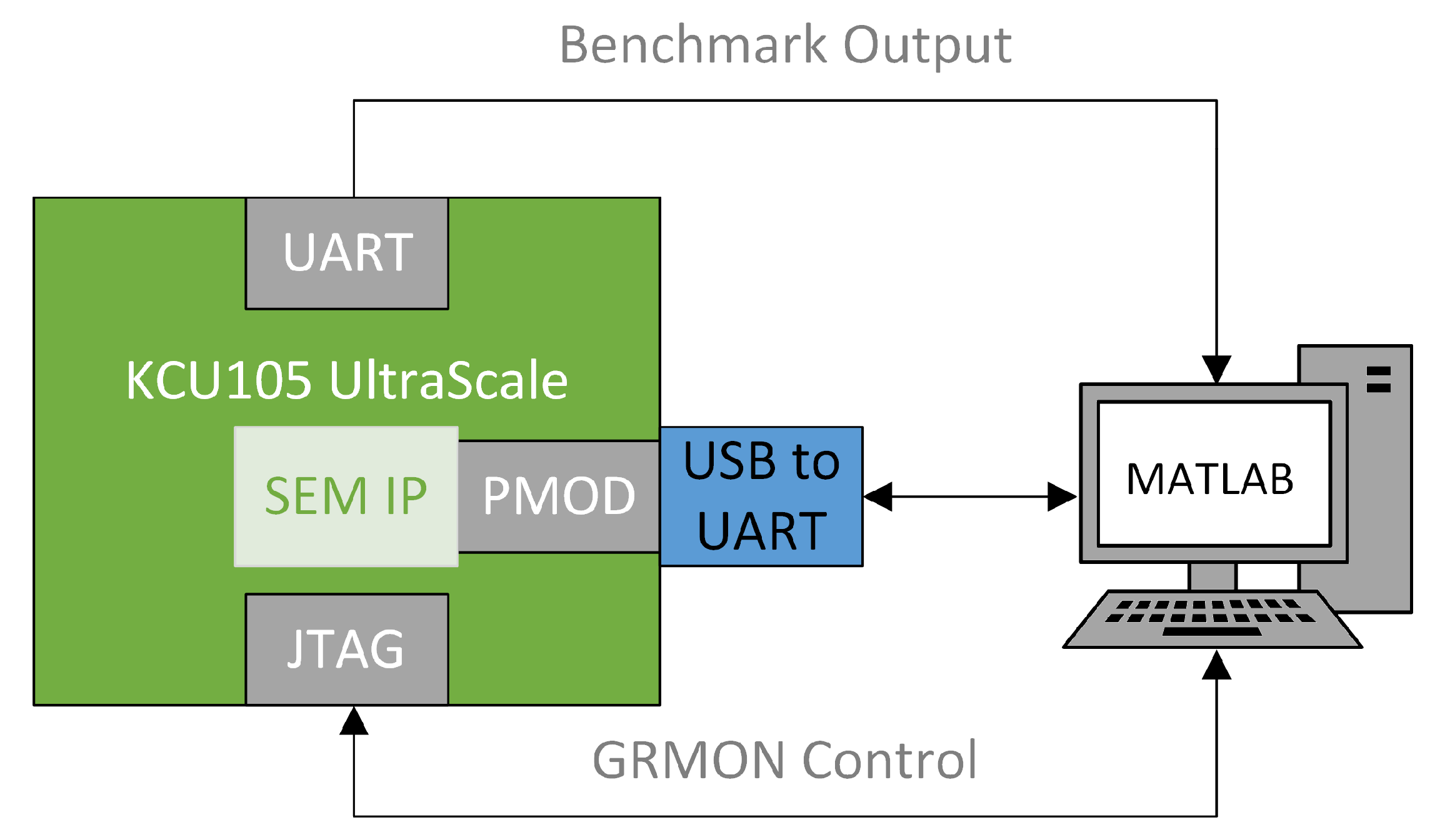
4. Experimental Set-Up

The fault injection experiments presented in this paper were performed on a Xilinx KCU105 evaluation board that consists of a Kintex UltraScale FPGA [17]. In particular, configuration memory errors were injected by using the Xilinx SEM IP Controller. The SEM IP can write in the configuration memory of an FPGA through the ICAP to correct errors. This feature can also be used to perform bit flips in the configuration memory. This approach requires a Digilent USB-UART peripheral module (PMOD) [18] and a serial port communication script running on a computer to control the injection procedure. In addition to the Digilent USB-UART PMOD and the communication script, the SEM IP requires a list containing the injection addresses in which the bit flips will be performed. To generate such addresses, the ACME tool developed by the ARIES Research Center at Universidad Nebrija was used. ACME is a tool that translates the configuration memory essential bits of an SRAM-based FPGA region into injection addresses for the Xilinx SEM IP Controller. It uses the Xilinx EBD file created by Vivado together with the coordinates of the FPGA region in which the DUT is placed to generate the mentioned list with the injection addresses [15]. To avoid injection side-effects, Vivado placement constraints were used to exclude the SEM IP resources from the DUT area.
To evaluate the correct behavior of the Rocket RISC-V processor implemented in the mentioned FPGA, the following four synthetic benchmarks were used for the tests:
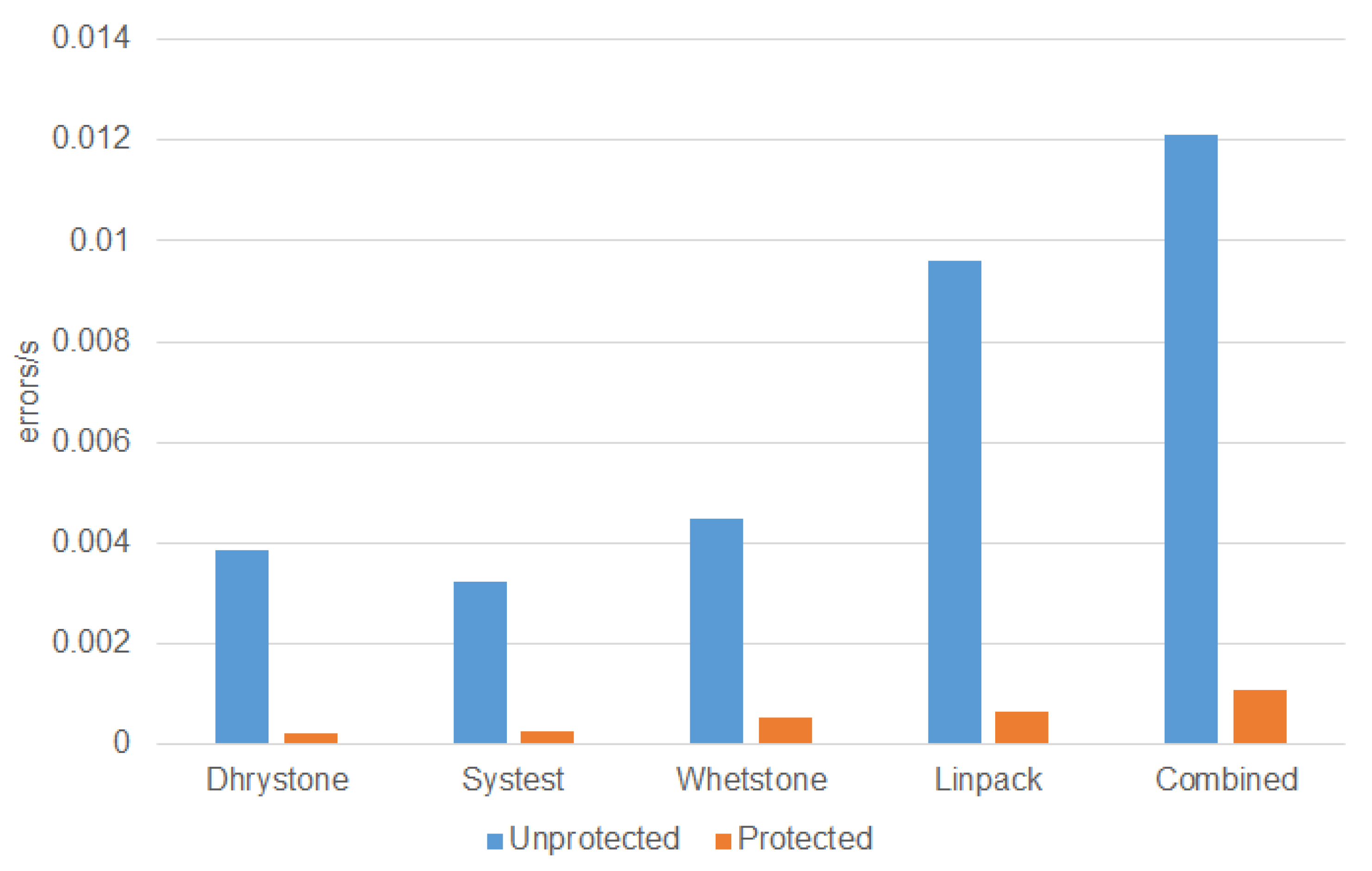
  • Dhrystone: A widely used integer benchmark that does not contain any floating point operation
  • Systest: An integer benchmark that checks the status of the processor with different tests
  • Whetstone: The floating point counterpart of the Dhrystone benchmark that is used to measure the floating point arithmetic performance of a processor
  • Linpack: A floating point benchmark that performs several linear algebra operations
The selected benchmark is loaded and executed in the microprocessor through the JTAG port of the KCU105 board by using GRMON, a general debug monitor for the LEON processor developed by Cobham Gaisler [19]. The outcome of the executed benchmark (i.e., the output messages generated by the benchmark during its execution) is received through the UART port of the KCU105 board.
A scheme is depicted in Figure 1 for a better understanding of the experimental set-up used.
The fault injection campaign procedure is run by using a MATLAB script that executes the following steps:
  • The DUT is programmed in the FPGA of the KCU105 board together with the SEM IP tool.
  • A golden simulation is performed where one of the four selected benchmarks is executed in the DUT in the absence of errors to obtain the correct outcome of the benchmark. The golden outcome of the benchmark is stored for later comparisons.
  • A command is sent to the SEM IP to inject a bit-flip at a random configuration memory frame.
  • A reset signal is sent to the DUT to initialize its internal state.
  • The selected benchmark is loaded in the DUT and then executed by using GRMON.
  • The outcome of the DUT is received and logged in a text file.
  • A command is sent to the SEM IP to correct the injected error.
  • Steps 3–7 are repeated until all the configuration memory errors have been injected.
Once the campaign ends, the text file with the benchmark outcomes for each injection is processed and compared to the golden outcome of the DUT to perform the classification described below:
  • No error: The outcome of the benchmark matches the golden outcome.
  • Error: The outcome of the benchmark does not match the golden outcome.
  • Hang: There is no outcome of the benchmark or the execution of the benchmark never ends, receiving continuous garbage information for a long period of time. This case is detected during Step 6 and it is logged in the text file as “hang”. To classify an error as “hang”, the execution time of each benchmark is previously measured in the absence of errors and a proper timeout is implemented in the MATLAB code depending on the current executed benchmark.
Finally, it should be mentioned that we performed 27,000 configuration memory injections for each benchmark to reduce the fault injection campaign runtime. This value implies a confidence interval of 95% with an error margin of approximately 0.6% according to Cochran’s sample size formula [20].

5. Experimental Results

As explained in Section 3, a procedure was followed to analyze the critical bits of the Rocket RISC-V processor and their relationship with the cross-section. In this section, the experimental results obtained after following this procedure are presented, as well as an application example of these results to calculate the error rate.

5.1. Characterization of the Unprotected Design

First, the unprotected Rocket RISC-V processor design was characterized by performing one fault injection campaign for each of the four selected benchmarks. The results for the unprotected design are summarized in Table 1. In this table, an additional column is included with a combined experiment (“Combined” column), in which the four benchmarks were executed one after the other. This column is used to illustrate a more general behavior of the processor. It should be noticed that this column is not the accumulated sum of the results obtained for the other benchmarks because, in this context, an injection is classified as “error” or “hang” when it affects the behavior of (at least) one of the four benchmarks.
Analyzing the percentage of errors for each benchmark, it can be observed that the floating point benchmarks (Whetstone and Linpack) have more errors, which is reasonable since the floating-point unit (FPU) of the microprocessor uses a significant amount of resources of the FPGA. Therefore, the probability of affecting a resource that is used by the benchmark increases. In general, the probability of an error affecting the output increases with the variety of instructions executed, as more elements of the microprocessor are used. Anyway, notice that (as explained in Section 2.2), the majority of the bit flips induced in the configuration memory are not producing an error in the execution of the benchmarks. As explained above, this proves that the majority of the bits flagged as essential by the design tool are not actually critical. To estimate the actual number of critical bits, let us consider that 100% of these critical bits would produce an effect in the unprotected system that would be observable at the output. This is not strictly true, since logic and temporal masking could prevent some of the induced errors from propagating to the output. However, just to work with the worst case, let us assume that there is no masking and therefore 100% of the induced errors would be observable at the output. In this way, the percentage of critical bits of the RISC-V executing the Dhrystone benchmark would be 3.10% (errors plus hangs), 2.60% for Systest, 3.61% for Whetstone, 7.70% for Linpack, and 9.68% for the combined experiment (see Table 2).
The percentages in the previous table mean that just a small fraction of the injected bits are critical, and therefore only these have to be considered when assessing the quality of the protection technique. Apart from that, additional information can be inferred by analyzing the results from the combined experiment. Since the same 27,000 locations of the bit flips were kept among the different benchmarks, the combined experiment illustrates the superset of all the individual critical bits obtained from each test. Therefore, the 9.68% of critical vs. essential bits ratio obtained for this experiment represents a more generic behavior of the processor.
Finally, to show the complexity of the fault injection process, Table 3 presents the execution time per injection for each benchmark. It should be mentioned that this execution time also includes the time that the GRMON needs to be initialized but, since this time is a constant for each benchmark, it does not affect the result for comparative purposes.

5.2. Characterization of the Protected Design

As mentioned above, the Rocket RISC-V processor was protected with a DTMR scheme. DTMR was applied to the instantiation of the Rocket subsystem by using the Mentor Precision Hi-Rel tool. This means that the DTMR was applied to the Verilog netlist produced by the Rocket chip generator. The triplication was done on FPGA element granularity, thus the synthesis tool triplicates all elements in the FPGA (FFs, LUTs, etc.). This DTMR-protected version of the Rocket RISC-V processor was tested by performing again different fault injection campaigns for each benchmark. The results are shown in Table 4.
First, it can be observed in the previous table that the protected version correctly executes the Dhrystone benchmark 99.95% of the time, 99.94% for Systest, 99.88% for Whetstone, 99.85% for Linpack, and 99.75% for the combined experiment. These percentages are close to the expected 100% for DTMR protection, but none of the experiments reach that ideal value. This is because the DUT input/output routing in SRAM-based FPGAs can also be affected by the injected configuration memory error. These errors can create malfunctions such as “hangs” in the microprocessor that cannot be corrected by a DTMR approach. However, the quantification of the effect of these errors in the system is not straightforward. It may seem that this effect is quite small, in the 0.05–0.25% range, but, again, we need to consider that many of the injected bit-flips are not producing an error in the system, not due to the quality of the protection, but because these bits are not critical (as proved in the characterization of the unprotected version). To calibrate this effect, let us assume that the percentage of critical bits in the protected (DTMR) version of the system is approximately the same as the percentage of the unprotected version (see Table 2). An important comment is that, depending on the selected protection technique, this assumption will be more or less precise. For a protection technique based on redundancy, in which the protection is achieved by replicating the base design n times (e.g., DTMR), the assumption will be more precise. It is true that there will be more components, for example the voter, but the number of critical bits would grow in the same proportion. This is why we chose DTMR to perform the study since it is a regular structure based on modular redundancy. On the other hand, protection techniques that are not based on modularity will have a number of critical bits not so extrapolated with respect to the unprotected version. In any case, the assumption will be the worst case of the number of critical bits.

5.3. Critical Bits Calculation

Based on the previous results obtained after testing both unprotected and DTMR-protected designs through fault injection, the percentage of undetected errors (P) in each design can be summarized, as shown in Table 5. These values are not normalized, i.e., all essential bits are taken as critical.
However, as previously mentioned, these values have to be normalized to make a fair comparison, or, in other words, to consider just the number of critical bits. To achieve this, the values in Table 5 are divided by the ratio obtained for the unprotected design (see Table 2). The results are shown in Table 6.
First, we can see that the top row (probability of error of the unprotected design) is now 100%. This gives more realistic information, meaning that 100% of the injections on critical bits produce an error (therefore ignoring the effect of the non-critical essential bits). Second, the values of the bottom row (probability of error of the protected design) have been normalized. For example, in the case of Dhrystone, this value has increased from 0.05% to 1.61% (i.e., 0.05 % × 100 / 3.10 ), since 3.10% is the percentage of critical bits for that benchmark). This means that, although the effect of the errors in the protected version is still small, it is larger than the initial 0.05%. Again, this is because we are ignoring the non-critical essential bits and considering the number of observed errors vs. the actual number of critical bits. With this normalization, the probability of error of the techniques, as a figure of merit of the achieved reliability, is more meaningful.
Finally, let us calculate the number of critical bits (N) for each scenario that, as stated above, can be used as a measure of the critical section of the circuit. We start with the number of essential bits of the unprotected and protected designs, which is given by the design tool. In this particular case, the number of essential bits of the unprotected design is 6,665,452 and the number of essential bits of the protected design is 23,045,386. Then, we obtain the number of critical bits for each benchmark by multiplying the number of essential bits and the critical vs. essential bits ratio obtained for the unprotected design (Table 2). The results of the obtained critical bits per benchmark, for the unprotected and protected designs, can be seen in Table 7.
In the next subsection, a practical use for the normalized percentage of errors and the number of critical bits is described.

5.4. Application Example: Error Rate Calculation

Let us suppose that we want to calculate the error rate for the two RISC-V designs analyzed above (the unprotected and the protected versions). For this example, we implemented the RISC-V versions on the FPGA board used in the experiments (Xilinx UltraScale), and we considered that the system is going to operate in LEO orbit, in the proximity of the South Atlantic Anomaly. To determine the absolute number of errors (U) that the system is going to receive, the following expression must be used:
U = Φ · σ · N · P ¯
where Φ is the flux that the system is receiving, σ is the physical cross-section of the FPGA, N is the number of critical bits, and P ¯ is the normalized probability that an induced bit flip will produce an error at the output. It should be noticed that both Φ and σ are a function of the linear energy transfer (LET), thus the integral of these parameters over the whole LET spectrum should be performed but, for the sake of simplicity, the formula presented in Equation (3) was used for the application example.
In this example, the values for Φ and σ were obtained from the literature. According to [21], the radiation flux of a LEO satellite in the South Atlantic Anomaly is almost 1.00 × 10 7 cm 2 · s 1 . The physical cross-section (i.e., the cross-section of the whole device) was obtained from [22] that the configuration memory cross-section of the Kintex UltraScale FPGA is estimated in 1.87 × 10 15 cm 2 /bit. Notice that this value is per bit, and represents the physical sensitivity of the device to the radiation. To obtain the cross-section of the design, we need to multiply σ by the total number of bits associated with that specific design. Based on the arguments in previous sections, this needs to be the number of critical bits of the design and not the number of all the essential bits (as the design tool provides). This is the reason the number of critical bits is relevant. The product σ · N can be used as a figure of merit of the cross-section of the design implemented in that specific FPGA. Therefore, Φ · σ · N represents the total number of bit flips that have been induced in the configuration memory. To obtain how many of those errors will propagate to the output, this value must be multiplied by the normalized probability of error, P ¯ .
After performing these calculations, the absolute number of errors per unit of time that can be expected for the described scenario is depicted in Table 8 and Figure 2 for a better comparison.

6. Conclusions

In this study, the reliability of a Rocket RISC-V processor implemented in a last generation Xilinx FPGA was assessed by conducting fault injection experiments on both an unprotected and a DTMR-protected design of the mentioned RISC-V. The experiments were performed while running several benchmarks. Specifically, it was found that, for the DTMR protected RISC-V, 99.9% of injected errors did not produce any error at the output. On the other side, it was obtained that, for the unprotected RISC-V, around 96% of injected errors did not create any wrong outcome. After investigating the reason of this phenomenon, it was found that many of the bits that Xilinx classifies as essential do not actually induce any error in the behavior, and therefore they cannot be considered critical. Based on this, a procedure to calculate the empirical percentage of critical bits is proposed in this paper to get a more realistic vision of the fault tolerance capability of the circuit. In addition, a new figure of merit of the cross-section offered by a design implemented in an FPGA is proposed. Finally, these concepts were applied to an example in which the error rate of an application was calculated. As future work, we will perform two different analyses. On the one hand, the individual modules of the RISC-V processor will be tested to determine what parts of the processor are more prone to errors. On the other hand, the fault injection campaign will be extended to study the effect of the critical bit accumulation, and how two bits that are not individually critical can become critical when both are affected at the same time.

Author Contributions

Conceptualization, J.A., R.W. and J.A.M.; Formal analysis, L.A.A., N.-J.W., L.S., A.S.-M., J.A., R.W. and J.A.M.; Investigation, L.A.A., N.-J.W., J.A. and J.A.M.; Project administration, J.A.; Supervision, L.S., A.S.-M., J.A., R.W. and J.A.M.; Validation, L.A.A., L.S., A.S.-M., J.A., R.W. and J.A.M.; Writing—original draft, L.A.A., A.S.-M. and J.A.M.; Writing—review & editing, L.A.A., L.S., A.S.-M., R.W. and J.A.M. All authors have read and agreed to the published version of the manuscript.

Funding

The work presented in this paper is part of an Innovation Triangle Initiative project 4000123876/18/NL/CRS funded by the European Space Agency (ESA).

Conflicts of Interest

The authors declare no conflicts of interest.

References

  1. Howard, J.W.; Hardage, D.M. Spacecraft Environments Interactions: Space Radiation and Its Effects on Electronic Systems; Tech. Report. TP-1999-209373; NASA: Washington, DC, USA, 1999. [Google Scholar]
  2. Oldham, T.R.; McLean, F.B. Total ionizing dose effects in MOS oxides and devices. IEEE Trans. Nucl. Sci. 2003, 50, 483–499. [Google Scholar] [CrossRef] [Green Version]
  3. Karnik, T.; Hazucha, P.; Patel, J. Characterization of soft errors caused by single event upsets in CMOS processes. IEEE Trans. Dependable Secur. Comput. 2004, 1, 128–143. [Google Scholar] [CrossRef] [Green Version]
  4. Lacoe, R.C.; Osborn, J.V.; Roga, R.; Brown, S.; Mayer, D.C. Application of hardness-by-design methodology to radiation-tolerant ASIC technologies. IEEE Trans. Nucl. Sci. 2000, 47, 2334–2341. [Google Scholar] [CrossRef]
  5. Asadi, H.; Tahoori, M.B. Soft error modeling and remediation techniques in ASIC designs. Microelectron. J. 2010, 41, 506–522. [Google Scholar] [CrossRef]
  6. Herrera-Alzu, I.; Lopez-Vallejo, M. Design techniques for Xilinx Virtex FPGA configuration memory scrubbers. IEEE Trans. Nucl. Sci. 2013, 60, 376–385. [Google Scholar] [CrossRef] [Green Version]
  7. Asanović, K.; Avizienis, R.; Bachrach, J.; Beamer, S.; Biancolin, D.; Celio, C.; Cook, H.; Dabbelt, D.; Hauser, J.; Izraelevitz, A.; et al. The Rocket Chip Generator; University of California, Berkeley, Tech. Report. UCB/EECS-2016-17; EECS Department: North York, ON, Canada, 2016. [Google Scholar]
  8. Entrena, L.; Garcia-Valderas, M.; Fernandez-Cardenal, R.; Lindoso, A.; Portela, M.; Lopez-Ongil, C. Soft error sensitivity evaluation of microprocessors by multilevel emulation-based fault injection. IEEE Trans. Comput. 2010, 61, 313–322. [Google Scholar] [CrossRef]
  9. Wissel, L.; Pheasant, S.; Loughran, R.; LeBlanc, C.; Klaasen, B. Managing soft errors in ASICs. In Proceedings of the IEEE 2002 Custom Integrated Circuits Conference, Orlando, FL, USA, 15 May 2002; pp. 85–88. [Google Scholar]
  10. Alderighi, M.; Casini, F.; D’Angelo, S.; Gravina, A.; Liberali, V.; Mancini, M.; Musazzi, P.; Pastore, S.; Sassi, M.; Sorrenti, G. A preliminary study about SEU effects on programmable interconnections of SRAM-based FPGAs. J. Electron. Test. 2013, 29, 341–350. [Google Scholar] [CrossRef]
  11. SymbiFlow Team. Project X-ray Documentation. Release 0.0-2853-g55ef667. Available online: https://readthedocs.org/projects/prjxray/downloads/pdf/latest/ (accessed on 8 January 2019).
  12. Alderighi, M.; Casini, F.; D’Angelo, S.; Pastore, S.; Sechi, G.R.; Weigand, R. Evaluation of single event upset mitigation schemes for SRAM based FPGAs using the flipper fault injection platform. In Proceedings of the 20th IEEE International Symposium on Defect and Fault-Tolerance in VLSI Systems (DFT 2007), Rome, Italy, 26–28 September 2007; pp. 105–113. [Google Scholar]
  13. Mogollon, J.M.; Guzman-Miranda, H.; Napoles, J.; Barrientos, J.; Aguirre, M.A. FTUNSHADES2: A novel platform for early evaluation of robustness against SEE. In Proceedings of the 12th European Conference on Radiation and Its Effects on Components and Systems, Sevilla, Spain, 19–23 September 2011; pp. 169–174. [Google Scholar]
  14. Le, R. Soft Error Mitigation Using Prioritized Essential Bits; Xilinx: San Jose, CA, USA, 2012. [Google Scholar]
  15. Aranda, L.A.; Sánchez-Macián, A.; Maestro, J.A. ACME: A tool to improve configuration memory fault injection in SRAM-Based FPGAs. IEEE Access 2019, 7, 128153–128161. [Google Scholar] [CrossRef]
  16. Xilinx. Soft Error Mitigation Controller; LogiCORE IP Product Guide (PG036). Available online: https://www.xilinx.com/support/documentation/ip_documentation/sem/v4_1/pg036_sem.pdf (accessed on 7 November 2019).
  17. Xilinx. KCU105 Board User Guide (UG917). Available online: https://www.xilinx.com/support/documentation/boards_and_kits/kcu105/ug917-kcu105-eval-bd.pdf (accessed on 7 November 2019).
  18. Digilent. PmodUSBUART Reference Manual. Available online: https://reference.digilentinc.com/_media/reference/pmod/pmod-interface-specification-1_2_0.pdf (accessed on 7 November 2019).
  19. Cobham Gaisler AB. GRMON3 User’s Manual. Available online: https://www.gaisler.com/doc/grmon3.pdf (accessed on 7 November 2019).
  20. Cochran, W.G. Sampling Techniques, 3rd ed.; John Wiley & Sons: New York, NY, USA, 1977. [Google Scholar]
  21. Tan, Y.C.; Chandrasekara, R.; Cheng, C.; Ling, A. Silicon Avalanche Photodiode Operation and Lifetime Analysis for Small Satellites. Opt. Express 2013, 21, 16946–16954. [Google Scholar] [CrossRef] [PubMed] [Green Version]
  22. Lee, D.S.; Allen, G.R.; Swift, G.; Cannon, M.; Wirthlin, M.; George, J.S.; Koga, R.; Huey, K. Single-Event Characterization of the 20 nm Xilinx Kintex UltraScale Field-Programmable Gate Array under Heavy Ion Irradiation. In Proceedings of the 2015 IEEE Radiation Effects Data Workshop (REDW), Boston, MA, USA, 13–17 July 2015; pp. 1–6. [Google Scholar]
Figure 1. Experimental set-up.
Electronics 09 00175 g001
Figure 2. Comparison between unprotected and protected designs in terms of errors per second.
Electronics 09 00175 g002
Table 1. Reliability results for the unprotected version of the Rocket RISC-V processor.
DhrystoneSystestWhetstoneLinpackCombined
No errors26,162 (96.90%)26,297 (97.40%)26,025 (96.39%)24,921 (92.30%)24,385 (90.31%)
Errors329 (1.22%)220 (0.81%)494 (1.83%)1213 (4.49%)1630 (6.03%)
Hangs509 (1.88%)483 (1.79%)481 (1.78%)866 (3.21%)985 (3.65%)
Total injections27,000 (100%)27,000 (100%)27,000 (100%)27,000 (100%)27,000 (100%)
Table 2. Critical vs. essential bits ratio obtained from the unprotected design characterization.
DhrystoneSystestWhetstoneLinpackCombined
3.10%2.60%3.61%7.70%9.68%
Table 3. Execution time per injection for each benchmark (in seconds).
DhrystoneSystestWhetstoneLinpackCombined
Execution time7.57.21215.442
Table 4. Reliability results for the DTMR-protected version of the Rocket RISC-V processor.
DhrystoneSystestWhetstoneLinpackCombined
No errors26,986 (99.95%)26,984 (99.94%)26,968 (99.88%)26,960 (99.85%)26,960 (99.75%)
Errors0 (0%)0 (0%)0 (0%)0 (0%)0 (0%)
Hangs14 (0.05%)16 (0.06%)32 (0.12%)40 (0.15%)67 (0.25%)
Total injections27,000 (100%)27,000 (100%)27,000 (100%)27,000 (100%)27,000 (100%)
Table 5. Not-normalized percentage of undetected errors for both unprotected and DTMR-protected versions of the Rocket RISC-V processor.
DhrystoneSystestWhetstoneLinpackCombined
P u n p r o t e c t e d 3.10%2.60%3.61%7.70%9.68%
P p r o t e c t e d 0.05%0.06%0.12%0.15%0.25%
Table 6. Normalized percentage of undetected errors for both unprotected and DTMR-protected versions of the Rocket RISC-V processor.
DhrystoneSystestWhetstoneLinpackCombined
P ¯ u n p r o t e c t e d 100%100%100%100%100%
P ¯ p r o t e c t e d 1.61%2.31%3.32%1.95%2.58%
Table 7. Number of critical bits for both unprotected and DTMR-protected versions of the Rocket RISC-V processor.
DhrystoneSystestWhetstoneLinpackCombined
N u n p r o t e c t e d 206,629173,302240,623513,240645,216
N p r o t e c t e d 714,407599,180831,9381,774,4952,230,793
Table 8. Errors per second of the unprotected and DTMR-protected designs.
DhrystoneSystestWhetstoneLinpackCombined
U u n p r o t e c t e d 3.86 × 10 3 3.24 × 10 3 4.50 × 10 3 9.60 × 10 3 1.21 × 10 2
U p r o t e c t e d 2.15 × 10 4 2.59 × 10 4 5.17 × 10 4 6.47 × 10 4 1.08 × 10 3

