Article

Time Domain Performance of Reconfigurable Filter Antenna for IR-UWB, WLAN, and WiMAX Applications

College of Intelligence Science and Technology, National University of Defense Technology, Changsha 410073, China
*
Author to whom correspondence should be addressed.
Electronics 2019, 8(9), 1007; https://doi.org/10.3390/electronics8091007
Submission received: 21 August 2019 / Revised: 5 September 2019 / Accepted: 7 September 2019 / Published: 9 September 2019

Abstract

:
A novel reconfigurable filter antenna with three ports for three dependent switchable states for impulse radio-ultrawideband (IR-UWB)/wireless local area network (WLAN)/worldwide interoperability for microwave access (WiMAX) applications is presented in this paper. Three positive-intrinsic-negative diodes, controlled by direct current, are employed to realize frequency reconfiguration of one ultra-wideband state and two narrowband states (2.4 GHz and 3.5 GHz). The time domain characteristic of the proposed antenna in the ultra-wideband state is studied, because of the features of the IR-UWB system. The time domain analysis shows that the reconfigurable filtering antenna in the wideband state performs similarly to the original UWB antenna. The compact size, low cost, and expanded reconfigurable filtering features make it suitable for IR-UWB systems that are integrated with WLAN/WiMAX communications.

1. Introduction

The need for reconfigurable antennas in various wireless communication systems has been increasing [1]. Ultrawideband (UWB) antennas are necessary for integrating other existing wireless networking technologies with impulse radio-UWB (IR-UWB) systems. Different types of radio frequency (RF) switches, such as gallium arsenide (GaAs) field effect transistor switches, micro electro-mechanical systems (MEMS) switches, positive-intrinsic-negative (PIN) diodes, and varactor diodes, have been used to enable frequency reconfiguration [2,3,4]. Among these components, the PIN diode is most preferred in such applications due to its fast switching time, low cost, and easy fabrication.
Many researchers have discussed using PIN diodes to enable reconfigurability, including frequency switching [2,5,6] and radiation pattern switching [7,8,9] with PIN diodes. Multiple reconfigurability of bandwidth switching, radiation pattern switching, and polarization switching are realized by PIN diodes in [4]. Generally, antenna radiation patterns are studied at one specific frequency in the research of reconfigurable antennas, and when referring to radiation patterns, the frequency domain is commonly considered [10].
However, in IR-UWB systems, frequency domain analysis cannot accurately and completely describe the antenna’s features, as a result of adopting a narrow pulse for targeting and positioning [11]. Additional time domain analysis of the antenna is required. Some parameters of the time domain have been proposed to characterize this feature. Previous studies [12,13,14,15] have proposed a new method to describe the time domain performance by studying the forward voltage gain (S21) and system fidelity factor (SFF) of the antennas. Other authors [16,17] have cited the importance of the time domain analysis of traditional UWB antennas and of the performance of their operating antennas. However, few time domain studies of the reconfigurable antenna have been conducted, which is essential to IR-UWB systems.
In this paper, a novel design of a reconfigurable filter antenna in one ultra-wideband state and two narrowband states for an IR-UWB system is presented. The time domain performance was determined by measurement compared to the original UWB antenna. The paper is organized as follows: Section 2 describes the design of the proposed antenna. Frequency and time domain analysis are studied in Section 3. Section 4 concludes the study.

2. Design of the Reconfigurable Filtering Antenna

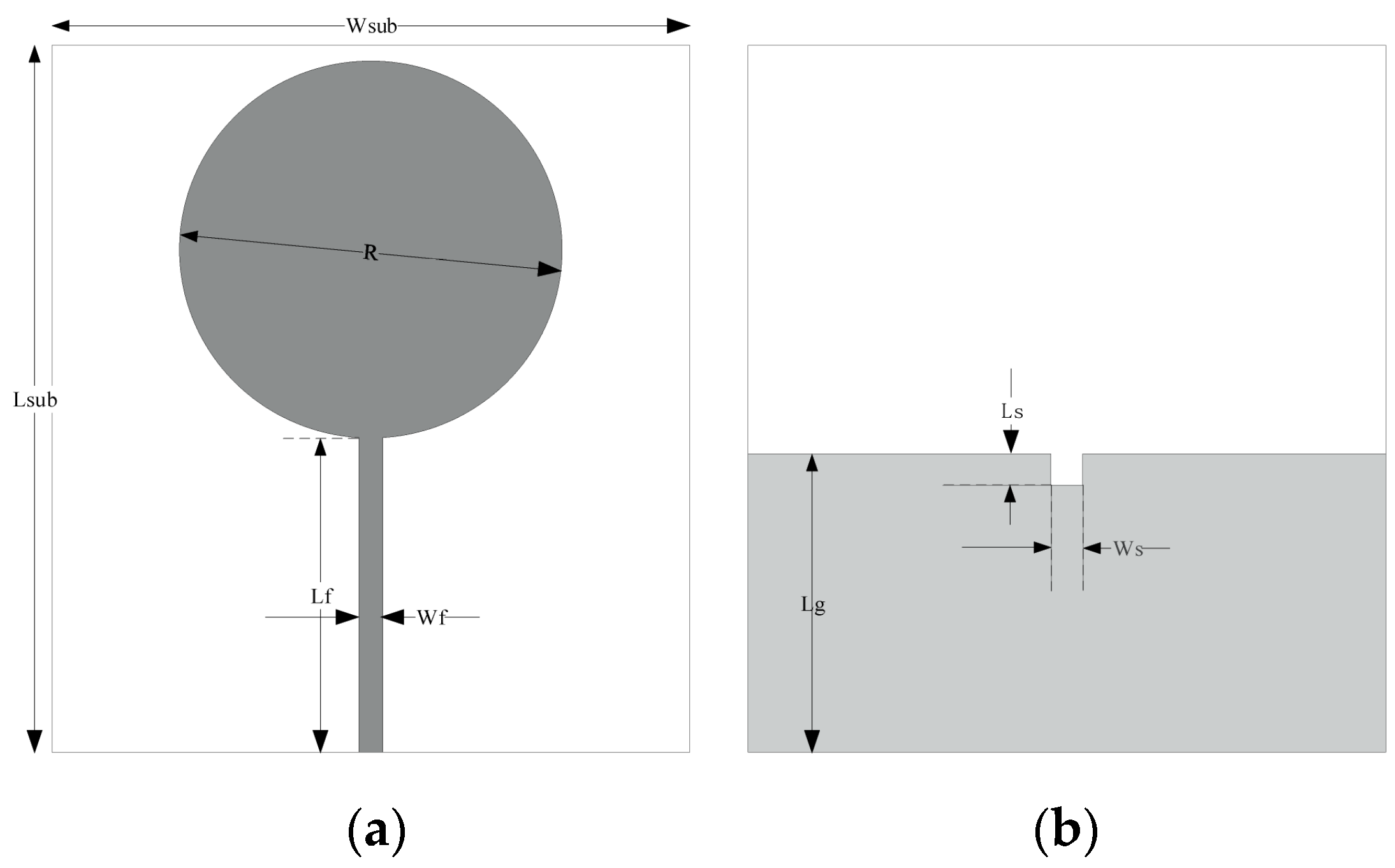
2.1. UWB Antenna Design

We chose a round-shaped monopole antenna and a defeated ground structure, which can broaden the operating frequency band. The layout of the original UWB antenna with its parameters are illustrated in Figure 1. The detailed values of various parameters used in the proposed antenna are listed in Table 1. The original UWB antenna was printed on a 1.6-mm-thick flame retardant-4 glass epoxy (FR-4) substrate (relative permittivity (εr) = 4.3). The substrate had a dimension of 80 × 90 mm2. The top layer consisted of a round-shaped patch as the radiating element, which was excited through a 50 Ω microstrip feeding line. The simulated and measured S11 of the original UWB antenna, shown in Figure 2, revealed that the designed antenna is able to support a wide frequency operating band of 1–4.7 GHz, which can cover the whole operating band of the IR-UWB system.

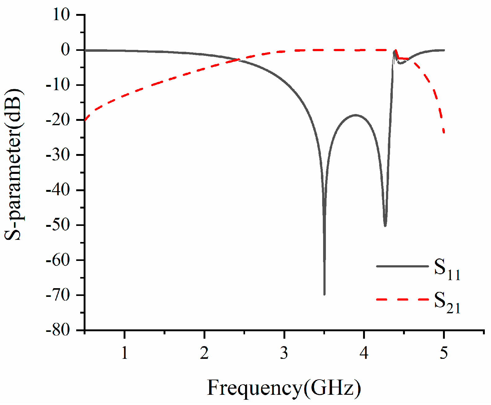
2.2. Band-Pass Filter Design

Referring to [18], we adopted a half-wave-length stepped impedance resonator filter due to its compact size and high stop-band rejection range. Figure 3 shows the layout of the adopted filter; the parameters were tuned to realize the 2.4 GHz and 3.5 GHz bandpass. Figure 4 and Figure 5 reveal that the designed band-pass filter is able to support a tuning center frequency from 2.4 GHz to 3.5 GHz with tuning parameters. Detailed values of the various parameters used in the proposed filters are listed in Table 2 and Table 3. The filter structure is simple and can be easily applied in related applications.

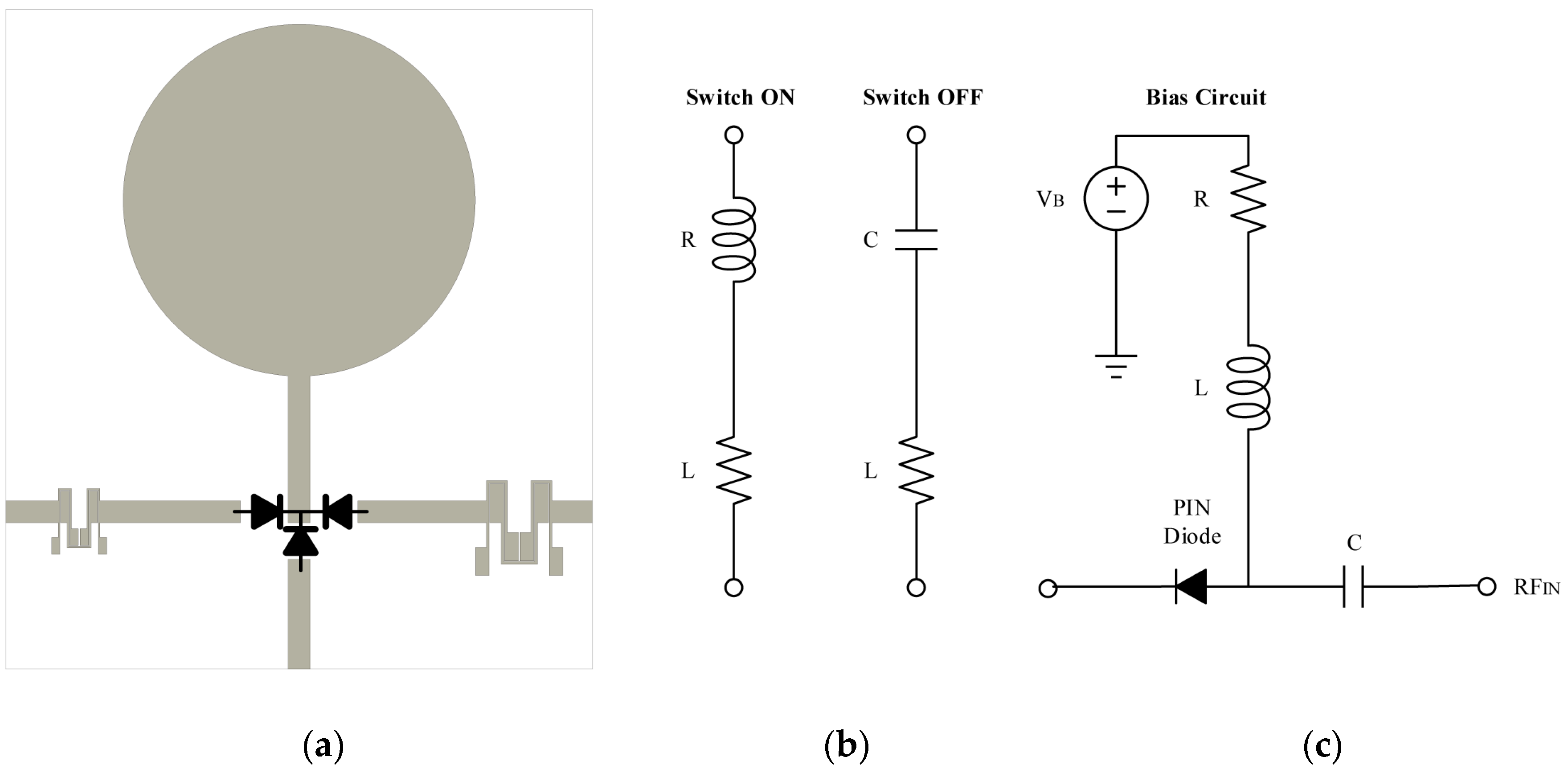
2.3. Reconfigurable Filter Antenna Design

As shown in Figure 6a, the proposed reconfigurable filtering antenna was designed to integrate the band-pass filter and the original UWB antenna. The whole structure of the proposed antenna includes three RF ports, a monopole, two band-pass filters, 50 Ω microstrip lines, and a direct current (DC) bias circuit for PIN diodes. Frequency reconfiguration is implemented by the PIN controlling path selections. Using three paths of 50 Ω microstrip lines and two designed band-pass filters to the monopole, filtering capability is obtained. Thus, three operating states with a frequency reconfigurable antenna were achieved, with no change in size.
Three PIN diodes were welded in suitable places to control the three paths to the radiating element: diode D1 was located in the slot line of the feeding line, and diodes D2 and D3 were placed on both sides of the feeding line. In the UWB state, D1 is on, D2 and D3 have no-bias voltage, the RF signal excites the antenna through port 1 and the two filters are off. When D1 is OFF, the antenna operates in a narrowband state, depending on whether either D2 or D3 is on. When D2 is on, the antenna is excited by the RF signal through port 2 and operates in the 3.5 GHz narrowband state, and operates in the in 2.4 GHz narrowband state when D3 is on.
As shown in Figure 6b, when on, the PIN diodes can be equivalent to an inductor (L) in series with a resistor (R); when off, the PIN diodes can be equivalent to an inductor (L) in series with a capacitor (C). In this paper, MACOM MADP-000907-14020 (MACOM, Lowell, Massachusetts, USA) was used as the PIN switch due to its low capacitance, 2 ns switching speed, and up to 70 GHz operating band [19]. The circuit parameters were set to R = 7.8 Ω, C = 0.025 pF, and L= 30 nH [20].
To avoid coupling of the RF signal and the bias current, we used a proper bias in this study [21]. As shown in Figure 6c, a capacitor was adopted for DC blocking. Therefore, resistance (R) was used to restrict the max bias current. Biasing voltages (VB) of 1.67 V and 0 V were applied to the circuit for ‘switch on’ and ‘switch off’ conditions, respectively.

3. Results and Discussion

3.1. Frequency Domain Performance

The proposed reconfigurable filtering antenna was fabricated and measured. The simulated and measured S11 in three states of the antenna are shown in Figure 7a–c. In the UWB state, diode D1 is on and diodes D2 and D3 are off. Figure 7a shows that the measured S11 performance is basically consistent with the simulated results; the proposed antenna in the UWB state can cover from 1 GHz to more than 5 GHz, which is sufficient for IR-UWB systems [17]. In the narrowband state, diode D1 is off. Depending on the bias circuits of D2 and D3, the narrowband states are switched. Figure 7b shows the 3.5 GHz narrowband when D2 is on. The measured results show that the antenna covers the 3.5 GHz WiMAX work band. When D3 is on and D2 is off, the antenna works in the 3.5 GHz narrowband state. Figure 7c shows that the measured antenna operates in the 2.4 GHz band.
As illustrated in Figure 7, the measured and simulated responses were compared. The comparison showed that the measured results of the proposed antenna correspond well in the three states. However, in the wideband state and the 3.5 GHz narrowband state, S11 shifts at the lower frequency of the whole operating band. Nevertheless, the result is valid and acceptable. Reasonable agreements between the simulated and measured results were obtained. The error is mainly due to the inaccurate modeling of PIN diodes and the fabrication and welding processes.
The port isolations of the proposed antenna are displayed in Figure 8a–c. In the three different operating states, high isolation performance (better than 20 dB) was obtained throughout the whole operating frequency band. High isolation indicates that the three states of the proposed antenna can operate dependently. The simulated and measured results in Figure 7 prove this.
The measured realized gains between the proposed reconfigurable filtering antenna and the original UWB antenna are compared in Figure 9. Figure 9 shows that the gains of the proposed filtering antenna are slightly lower than the original UWB antenna, which is mainly caused by insertion loss of additional filter structures and PIN diodes.

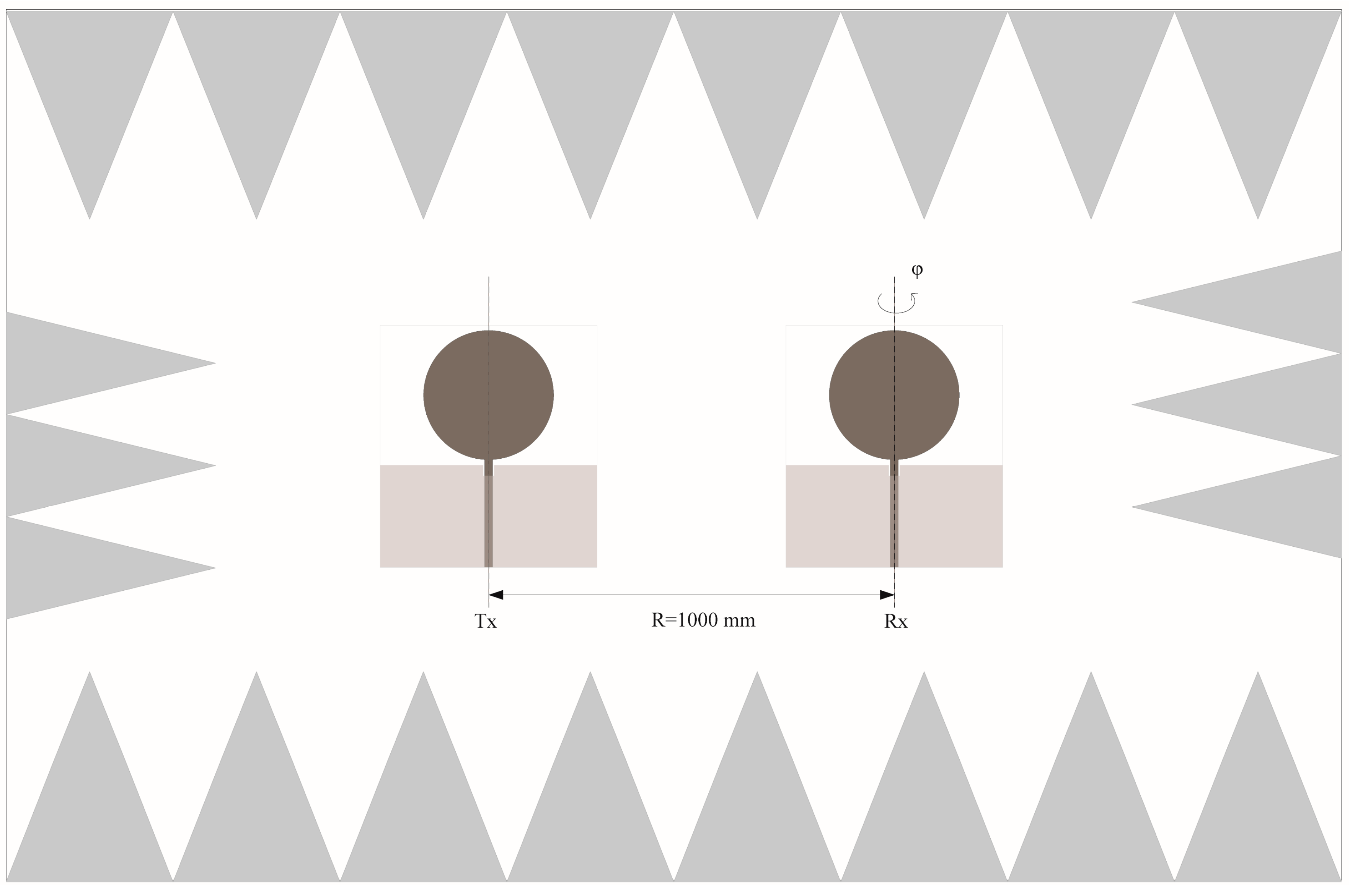
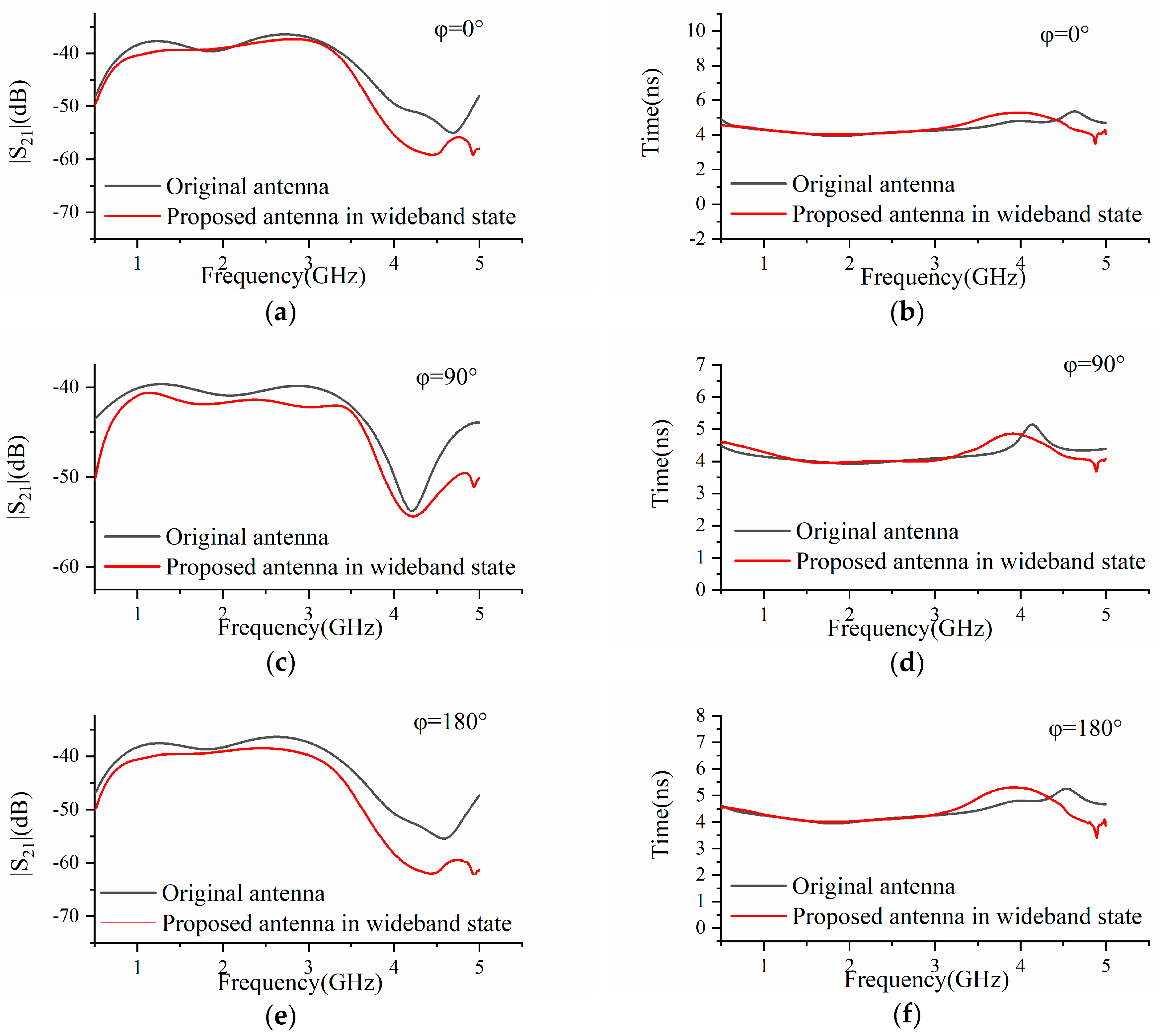
3.2. Time Domain Performance in Wideband State

As shown in Figure 10, the time domain performance of the antenna was measured in an anechoic chamber. With the transmitting antenna oriented at φ = 0°, the receiving antenna was rotated by φ = 0°, 90°, and 180°, which represent the typical working positions of a pair of antennas. S21 and group delay were measured directly from this experiment setup.
To characterize the time domain performance of an antenna, different parameters from the frequency domain were studied. The system fidelity factor (SFF) is the most used parameter to analyze time, frequency, and space together. The method is described in detail by the authors of [15] and in our experiment, SFF was obtained as follows. First, S21 was measured using the experimental setup, as shown in Figure 10. Then, the received signal was calculated by Fourier transform. The SFF was then calculated as follows (the system transform function H(ω) can be substituted by the measured S21):
R s ( ω ) = F F T ( T S ( ω ) ) H ( ω ) ,
R s ( t ) = I F F T ( R S ( ω ) ) ,
S F F = m a x n { T s ( t ) R s ( t + τ ) d τ [ | T s ( t ) | 2 d t ] 1 / 2 [ | R s ( t ) | 2 d t ] 1 / 2 } ,
where Ts(t) denotes the transmitted excitation signal, Rs(t) denotes the radiated signal in the received antenna, t denotes the time, H(ω) denotes the system transform function, ω denotes the frequency and τ denotes the shifted variable between Ts(t) and Rs(t) in convolution.
The S21 magnitude and group delay versus frequency characteristics for both antennas are depicted in Figure 11. For the proposed filtering antenna, the group delay is almost linear through the whole operating band. At φ = 0°, the group delay is 5 ns, and 4.5 ns at φ = 90° and 180°. The group delay of the proposed antenna is almost consistent with the original. However, at higher frequencies, a shift away from the original antenna occurs. A similar phenomenon can be found through the comparison of S21. A relative difference from 3.5 GHz to 5 GHz was observed. The difference is mainly due to the relative difference in the realized gains between the adopted filtering structure and the original UWB antenna within an acceptable range. Nevertheless, the result is valid and workable. These results indicate that the proposed filtering antenna obtains a similar S21 response and group delay, in comparison with the original UWB antenna.
The calculated output signals for both antennas for various φ are demonstrated in Figure 12. The proposed antenna has a similar output signal in comparison with the original UWB antenna. SFF can then be calculated by the coefficient of correlation between Ts(t) and Rs(t). The results are provided in Table 4.
A fidelity more than 0.8 indicates that the source signal is undistorted through material propagating, such that the received pulse waveform can be completely characterized [16]. The calculated values of the fidelity factor for both the original UWB antenna and the proposed reconfigurable antenna are listed in Table 4. Table 4 shows that the highest SFF (0.93) is obtained at φ = 0° and the differences in various φ values are small. A reasonable agreement was obtained between the simulated and measured SFF results. A similar phenomenon was found through comparison of the original UWB antenna. We observed that the fidelity factor of the original UWB antenna is better than that of the proposed reconfigurable filtering antenna. The difference is mainly due to the additional filtering structures insertion loss and the use of PIN diodes. However, the measured system fidelity factor (>0.82) was still high. The calculated SFF indicates that the proposed filtering antenna obtains a similar time domain performance in comparison with the original antenna.
Table 5 compares the proposed antenna with other antennas reported in the literature. The novelty of the proposed antenna lies in its simple shape, its ability to efficiently reconfigure the frequency and extra analysis of time domain performance. It is noteworthy that the proposed antenna has expanded frequency reconfiguration, without degrading the antenna’s time domain performance. The reconfigurable antenna for IR-UWB can integrate new working patterns without changing the original antenna’s features and size.

4. Conclusions

In this paper, a novel reconfigurable filter antenna was proposed for IR/UWB applications integrated with WLAN and WiMAX, and is suitable for many other communications. Besides the traditional frequency domain analysis, the time domain performance of the proposed antenna, which uses a PIN reconfigurable technique, was studied. The proposed antenna was fabricated and tested, and the time performance was studied in terms of measured S21, group delay, and calculated SFF. A dependent operating band was obtained through frequency domain analysis, with reasonable agreement of the time domain performance between the proposed reconfigurable filtering antenna and the original UWB antenna. These results indicate that the reconfigurable filtering antenna can integrate the WLAN and WiMAX narrowband with the IR-UWB operating band without changing the size and time domain performance compared with the original UWB antenna. These features enable the proposed filtering antenna to be widely used in IR-UWB systems integrated with WLAN/WiMAX and many other communications, which is essential for the miniaturization of the RF front in WSN applications, where multiple communications are needed.

Author Contributions

Conceptualization, Z.Z.; methodology, Z.P.; validation, Z.Z.; investigation, Z.Z.; writing—original draft preparation, Z.Z.; writing—review and editing, Z.P.; visualization, Z.Z.; supervision, Z.P.; project administration, Z.P.; funding acquisition, Z.P.

Funding

This research received no external funding.

Acknowledgments

The authors are grateful to the reviewers and editors for their valuable feedback on our work that helped to improve the quality of this paper.

Conflicts of Interest

The authors declare no conflict of interest.

References

  1. Liang, Z.; Zhang, G.; Dong, X.; Huo, Y. Design and Analysis of Passband Transmitted Reference Pulse Cluster UWB Systems in the Presence of Phase Noise. IEEE Access 2018, 6, 14954–14965. [Google Scholar] [CrossRef]
  2. Yao, C.; Longfang, Y.; Jianliang, Z.; Yanhui, L.; Liang, Z.; Miao, Z.; Qing, H.L. Frequency Reconfigurable Circular Patch Antenna with an Arc-Shaped Slot Ground Controlled by PIN Diodes. Int. J. Antennas Propag. 2017, 2017, 1–7. [Google Scholar] [CrossRef]
  3. Yang, X.-L.; Lin, J.-C.; Chen, G.; Kong, F.-L. Frequency reconfigurable antenna for wireless communications using GaAs FET switch. IEEE Antennas Wirel. Propag. Lett. 2014, 14, 807–810. [Google Scholar] [CrossRef]
  4. Selvam, Y.P.; Elumalai, L.; Alsath, M.G.N.; Kanagasabai, M.; Subbaraj, S.; Kingsly, S. Novel frequency-and pattern-reconfigurable rhombic patch antenna with switchable polarization. IEEE Antennas Wirel. Propag. Lett. 2017, 16, 1639–1642. [Google Scholar] [CrossRef]
  5. Nguyen-Trong, N.; Piotrowski, A.; Fumeaux, C. A frequency-reconfigurable dual-band low-profile monopolar antenna. IEEE Trans. Antennas Propag. 2017, 65, 3336–3343. [Google Scholar] [CrossRef]
  6. Konca, M.; Warr, P.A. A frequency-reconfigurable antenna architecture using dielectric fluids. IEEE Trans. Antennas Propag. 2015, 63, 5280–5286. [Google Scholar] [CrossRef]
  7. Hossain, M.A.; Bahceci, I.; Cetiner, B.A. Parasitic layer-based radiation pattern reconfigurable antenna for 5G communications. IEEE Trans. Antennas Propag. 2017, 65, 6444–6452. [Google Scholar] [CrossRef]
  8. Tran, H.H.; Nguyen-Trong, N.; Le, T.T.; Park, H.C. Wideband and multipolarization reconfigurable crossed bowtie dipole antenna. IEEE Trans. Antennas Propag. 2017, 65, 6968–6975. [Google Scholar] [CrossRef]
  9. Liu, B.-J.; Qiu, J.-H.; Wang, C.-L.; Li, G.-Q. Pattern-reconfigurable cylindrical dielectric resonator antenna based on parasitic elements. IEEE Access 2017, 5, 25584–25590. [Google Scholar] [CrossRef]
  10. Deng, J.; Hou, S.; Zhao, L.; Guo, L. A reconfigurable filtering antenna with integrated bandpass filters for UWB/WLAN applications. IEEE Trans. Antennas Propag. 2017, 66, 401–404. [Google Scholar] [CrossRef]
  11. Huo, Y.; Dong, X.; Lu, P. Ultra-wideband transmitter design based on a new transmitted reference pulse cluster. ICT Express. 2017, 3, 142–147. [Google Scholar] [CrossRef]
  12. Quintero, G.; Zurcher, J.; Skrivervik, A. Omnidirectional pulse dispersion of planar circular monopoles. In Proceedings of the 2009 IEEE International Conference on Ultra-Wideband, Vancouver, BC, Canada, 9–11 September 2009; pp. 395–399. [Google Scholar]
  13. Quintero, G.; Zurcher, J.-F.; Skrivervik, A.K. System fidelity factor: A new method for comparing UWB antennas. IEEE Trans. Antennas Propag. 2011, 59, 2502–2512. [Google Scholar]
  14. Koohestani, M.; Skrivervik, A.K.; Moreira, A.A. System fidelity factor evaluation of wearable ultra-wideband antennas for on-body communications. IET Microw. Antennas Propag. 2015, 9, 1054–1058. [Google Scholar] [CrossRef]
  15. Koohestani, M.; Pires, N.; Moreira, A.A.; Skrivervik, A.K. Time-domain performance of patch-loaded band-reject UWB antenna. Electron. Lett. 2013, 49, 385–386. [Google Scholar] [CrossRef]
  16. Singhal, S.; Singh, A.K. CPW-fed hexagonal Sierpinski super wideband fractal antenna. LET Microw. Antennas Propag. 2016, 10, 1701–1707. [Google Scholar] [CrossRef]
  17. Valizade, A.; Rezaei, P.; Orouji, A.A. A design of UWB reconfigurable pulse transmitter with pulse shape modulation. Microw. Opt. Technol. Lett. 2016, 58, 2221–2227. [Google Scholar] [CrossRef]
  18. Gorur, A. A novel dual-mode bandpass filter with wide stopband using the properties of microstrip open-loop resonator. IEEE Microw. Wirel. Compon. Lett. 2002, 12, 386–388. [Google Scholar] [CrossRef]
  19. MACOM. Available online: https://www.macom.com/products/product-detail/MADP-000907-14020P (accessed on 15 August 2019).
  20. Yang, H.H.; Yang, F.; Xu, S.H.; Li, M.K.; Cao, X.Y.; Gao, J. Design and verification of an electronically controllable ultrathin coding periodic element in Ku band. Acta Phys. Sin. 2016, 65, 54102. [Google Scholar]
  21. Yeom, I.; Choi, J.; Kwoun, S.-S.; Lee, B.; Jung, C. Analysis of RF Front-End Performance of Reconfigurable Antennas with RF Switches in the Far Field. Int. J. Antennas Propag. 2014, 2014, 1–14. [Google Scholar] [CrossRef]
Figure 1. Layout of the original ultrawideband (UWB) antenna: (a) top view; (b) bottom view.
Electronics 08 01007 g001
Figure 2. Simulated and measured input port voltage reflection coefficient (S11) of the original UWB antenna.
Electronics 08 01007 g002
Figure 3. Layout of the band-pass filter.
Electronics 08 01007 g003
Figure 4. The simulated scattering parameters (S-parameters) of filter at 2.4 GHz.
Electronics 08 01007 g004
Figure 5. The simulated S-parameters of filter at 3.5 GHz.
Electronics 08 01007 g005
Figure 6. Proposed filter antenna and bias circuit for positive-intrinsic-negative (PIN) diode: (a) the proposed antenna, (b) equivalent circuits for the on and off states of the PIN diode, and (c) bias circuit for PIN diodes.
Electronics 08 01007 g006
Figure 7. Summary of the S11 of the reconfigurable antenna: (a) UWB state (D1 on, D2 and D3 off); (b) 3.5 GHz narrowband (D2 on, D1 and D3 off); and (c) 2.4 GHz narrowband (D3 on, D1 and D2 off).
Electronics 08 01007 g007aElectronics 08 01007 g007b
Figure 8. Summary of the simulated port isolations of the reconfigurable filtering antenna: (a) UWB state (D1 on, D2 and D3 off); (b) 2.4 GHz narrowband (D2 on, D1 and D3 off); and (c) 3.5 GHz narrowband (D3 on, D1 and D2 off).
Electronics 08 01007 g008aElectronics 08 01007 g008b
Figure 9. Comparison of the measured realized gains between the proposed antenna and the UWB antenna.
Electronics 08 01007 g009
Figure 10. Measurement setup inside an anechoic chamber (Transmitted (Tx), Received (Rx)).
Electronics 08 01007 g010
Figure 11. Measurement summary of S21 magnitude and group delay for the original and proposed antennas at various φ: (a) S21 magnitude and (b) group delay at φ = 0°, (c) S21 magnitude and (d) group delay at φ = 90°, and (e) S21 magnitude and (f) group delay at φ = 180°.
Electronics 08 01007 g011
Figure 12. The calculated pulse shapes at the passive antenna output from measurement at various φ: (a) φ = 0°, (b) φ = 90°, and (c) φ = 180°.
Electronics 08 01007 g012aElectronics 08 01007 g012b
Table 1. Antenna parameters and their values.
Parameter Value (mm)ParameterValue (mm)ParameterValue (mm)
Wsub80Wf3R24
Lsub90Lf41Lg38
Ws4Ls4--
Table 2. Different parameters of the filter and their values at 2.4 GHz.
Parameter Value (mm)ParameterValue (mm)ParameterValue (mm)
W11.89L1 3.85S00.3
W20.38L23.86S10.10
t3L31.33Wf3
Table 3. Different parameters of the filter and their values at 3.5 GHz.
Parameter Value (mm)ParameterValue (mm)ParameterValue (mm)
W11.13L1 2.31S00.3
W20.23L22.01S10.10
t1.66L30.8Wf3
Table 4. System fidelity factor for the UWB monopole antenna and the proposed antenna.
φSystem Fidelity Factor
Original UWB AntennaProposed Reconfigurable Filtering Antenna
SimulatedMeasuredSimulatedMeasured
0.950.920.930.9
90°0.910.860.870.83
180°0.870.840.850.82
Table 5. Performance comparison with other designs in the literature.
Ref.ReconfigurationActuatorsMode NumberTime Domain Analysis
[2]Frequency5 PINs6 (narrowband)No
[3]Frequency1 FET2No
[7]Frequency4 PINs12 (narrowband)No
[16]No--Yes
This workFrequency3 PINs1 wideband, 2 narrowbandYes

