Article

Individual Phase Full-Power Testing Method for High-Power STATCOM

State Key Laboratory of Disaster Prevention and Reduction for Power Grid Transmission and Distribution Equipment, State Grid Hunan Electric Company Limited Disaster Prevention and Reduction Center, Changsha 410129, China
*
Author to whom correspondence should be addressed.
Electronics 2019, 8(7), 754; https://doi.org/10.3390/electronics8070754
Submission received: 28 May 2019 / Revised: 27 June 2019 / Accepted: 29 June 2019 / Published: 4 July 2019
(This article belongs to the Special Issue Power Converters in Power Electronics)

Abstract

:
For a high-power static synchronous compensator (STATCOM), a full-power pre-operation test in the factory is necessary to ensure the product quality of a newly manufactured one. But owing to the hardware limitation and cost of test platform, such test is currently too difficult to conduct in the factory, thus it poses great risk to the on-site operation and commissioning. To address this issue, this paper proposes an individual phase full-power testing method for STATCOM. By changing the port connection, three-phase STATCOM was reconstructed into a structure that two phases are in parallel and then in series with the third-phase, and then connected to two phases of the rated voltage grid. Then by rationally matching the voltage and current of three phases, the parallel phases can get a reactive current hedging under both the rated voltage and rated current, meanwhile three phases maintain their active power balance. As a result, STATCOM gets a phase full-power tested phase by phase. The simulation results in Matlab/Simulink show that, under the proposed test system, both the voltage and current of the parallel two phases get their rated values while the grid current is only about 3% of the rated current, meanwhile the DC-link voltage of each phase converter is stabilized. Compared with other testing methods for STATCOM, this method requires neither extra hardware nor high-capacity power supply to construct the test platform, but it can simultaneously examine both the entire main circuit and a large part of the control system in STATCOM. Therefore, it provides a cost-effective engineering method for the factory test of high-power STATCOM.

1. Introduction

Static synchronous compensator (STATCOM) is an effective solution for fast voltage/reactive power support during normal and faulty conditions [1,2]. During the last decades, much research has been carried out on its structure, control, modulation, and application [3,4,5,6,7]. For medium-voltage application, STATCOM usually adopts the multi-level converter topology, including the flying-capacitor multi-level converter [8], diode-clamped multilevel converter [9], and cascaded multi-level converter [10,11,12]. Since the modular multilevel converter (MMC) topology was proposed and applied [13], MMC-based STATCOM has gained growing attention because of its outstanding performance, such as a low harmonic, low losses, scalability, and redundant design [14,15,16]. Especially with the development of new energy power generation, it has obtained wide applications and has become the standard configuration in wind farms and photovoltaic power plants to improve low voltage ride through capability [17,18]. In most applications, its capacity is generally 10–100 Mvar. In 2018, South Korea built three ±400 Mvar STATCOMs, which are the world largest [19].
To ensure the safe, reliable, and stable operation of a newly manufactured STATCOM, a complete set of pre-operation tests are necessary. The standard IEEE P1052/08 [20] contains a special chapter to guide STATCOM testing, and specifies the factory test items of STACOM components, such as switching devices and controls. IEC 62927 defined the detailed requirements of electrical testing for STATCOM converter [21]. It lists many test items and objectives of value or value section, but rarely gives the corresponding test circuit or method. For the testing of STATCOM controls, a real-time digital simulator (RTDS) is usually employed to form a hardware- in-the-loop test system where the main circuit part is digitally modeled [22,23]. It can comprehensively test the control and protection systems, but cannot evaluate any main power component. For the testing of STATCOM value, the common method is to employ two submodules to form a back-to-back test platform [24,25]. It can check the converter adequacy with regard to current, voltage, and temperature stresses in various operation conditions. But it requires an extra DC voltage source connected to the DC-bus of one submodule, so that the active power loss of the submodules during operation can be supplemented. It applies to submodules rather than value section, which consist of several submodules, because the latter does not have a common DC-bus. In fact, the most critical difficulty for value section tests is the requirement for energy supplements. A typical test method for value section is that two value sections are connected in parallel to a single-phase source. One section generates inductive reactive current, while the other generates capacitive reactive current; meanwhile the voltage source provides a certain current to supplement the active losses of value sections. Because the medium voltage distribution network is usually three-phase three-wire system, this method requires a single-phase high-power voltage source instead of the grid, resulting in higher test platform cost. In [26], an equivalent testing method was presented for full-power testing of STATCOM converter. It employs an additional high-voltage DC source and two low-voltage DC sources besides two tested STATCOM converters. These DC sources are used to charge the tested converters and compensate their active loss during operation. This also leads to high platform cost and a large footprint.
All these testing methods are for individual component of STATCOM, but not for a complete machine. But the performance of STATCOM depends on, not only individual components, but also component assembly, components wiring, and mutual coordination among devices. Therefore, it is necessary to conduct a whole machine test for a newly manufactured STATCOM. For the testing of whole STATCOM, an intuitive idea is to directly carry out a full-power test in the factory. Since the STATCOM rating is usually far beyond the power supply capacity of a factory, such an idea is not feasible. An alternative option is to employ two STATCOMs to form a back-to-back test platform [27]. One is operated as test object to output the rated reactive current, while the other is used as an accompanying device to output the opposite reactive current to neutralize the former, thereby maintaining the tiny total grid current. It can test the actual performance of the whole STATCOM, but requires an extra STATCOM besides the tested one, resulting in very high cost and poor utilization. Moreover, it has high requirement for synchronous coordinated control of these two STATCOMs. Therefore, such a test is almost impossible in the practical applications. In [28], a current closed-loop test method for ±100 Mvar STATCOM was proposed, based on the principle of equal potential. Firstly, three-phase STATCOM was connected to the grid to charge, and then disconnected from the grid and short-circuit at the three-phase ports to conduct zero-voltage full-current closed-loop operation. It can conveniently verify the capability of current control as well as voltage insulation level of a complete STATCOM. However, under this method, STATCOM operates either, at high voltage or high current and, therefore, cannot test the actual operating characteristics at both the rated voltage and rated current. Moreover, it can only run for a short time so it cannot be used for long-term power assessment of the STATCOM.
To overcome these problems, this paper proposes an individual phase full-power testing method for STATCOM. In this method, three-phase STATCOM was reconstructed into a structure that two phases are in parallel and then series with the third-phase. Then, by rationally matching the voltage and current of each phase, the parallel two phases can steadily operate under both the rated voltage and current, thus realize a phase full-power test. The corresponding math relationship was analyzed and a double-loop control system was designed. A simulation was carried out in Matlab, and the simulation results show that STATCOM can stably operate under the proposed system.

2. Circuit Configuration and Operation Principle

The circuit configuration of the proposed testing method is shown in Figure 1. It can seem that one phase port of the normal STATCOM is disconnected from the grid, and then shorted to one of the other two phases. Its equivalent circuit model is shown in Figure 2, where the A-phase and B-phase arms are connected in parallel, and then in series, with the C-phase to a single-phase voltage source, whose amplitude equals the rated line voltage rather than the rated phase voltage.
Under the aforementioned structure, three phase converters are individually controlled as follows:
(1) The output voltage of the C-phase converter was properly adjusted so that the amplitude of the A-phase voltage is just equal to its rated phase voltage, namely, the C-phase voltage is equal to the vector difference between the access line voltage and the expected A-phase voltage.
(2) The currents in the parallel two phases were controlled to perform a phase-to-phase reactive current hedging with the rated current amplitude, namely, one phase follows the rated capacitive reactive current, while the other with the rated inductive reactive current.
In this way, for the A-phase or B-phase arm (including the converter value and filter reactance), both its voltage and current reached the rated values, thus achieving a phase full-power operation. Moreover, since the reactive currents form a circulation between A-phase and B-phase arms, the grid current is tiny and close to zero, thus the power supply capacity of such test platform is relatively small and easy to implement.
Similarly, by changing the shorted phase, the full power test for B-phase or C-phase converter can also be realized. Then all of three phases are individually tested at phase full-power condition, so this method can be named as individual phase full-power testing method.

3. Mathematical Model of the Individual Phase Full-Power Testing System

3.1. Basic Relationship and Constraints

In the equivalent circuit model shown as Figure 2, the voltage and current of three phase arms meet the basic relationship as following:
{ u A O = R A i A + L A d d t i A + u a O u A O = R B i B + L B d d t i B + u b O u C O = R C i C + L C d d t i C + u c O
{ i C =   ( i A + i B ) u C O = u A O u A C
where uAO, uCO represent the arm voltages of A-phase and C-phase (i.e., uAO is the voltage difference between the A-phase port A and the internal neutral point O in Figure 2, similar is uCO). iA, iB, and iC are the arm currents. uaO, ubO, and ucO are the output voltage of three converters (i.e., uaO is the voltage difference between the port a in Figure 2 and the neutral point O, similar are ubO and ucO). RA, RB, and RC are the equivalent resistance of each arm, LA, LB, and LC are the inductance of each arm. While, uAC represents the grid access voltage between the A-phase and C-phase ports, and depends mainly on the grid rather than the STATCOM.
Considering the defined operating conditions of this test system, the above voltages satisfy the following constraints: (1) The amplitude of A-phase voltage uAO (not the A-phase converter output voltage uaO) equals to the rated phase voltage of STATCOM to reach the rated voltage condition; (2) the amplitude of line voltage uAC equals to the rated line voltage; (3) the amplitude of C-phase converter output voltage ucO cannot exceed its maximum allowable range. Since the C-phase current in this test system is far less than its rated value, its voltage drop across resistance and inductance is very tiny. Thus, the amplitude of C-phase arm voltage uCO is very close to that of C-phase converter voltage ucO. In short, the amplitudes of the above voltages satisfy the following constraints:
{ u A O = U p N u A C = U l N = 3 U p N u C O U c max
where UpN, and UlN, respectively represent the amplitudes of the rated phase and line voltages of STATCOM. While, Ucmax represents the maximum output voltage of every phase converter, generally, it is larger than the rated phase voltage of STATCOM.
Ideally, there is only the rated amplitude of inductive/capacitive reactive current in A-phase and B-phase arms, while C-phase current is zero (because A-phase and B-phase arms constitute a circulating current). In fact, due to the loop resistance and switching device loss in every phase, each phase requires the absorption of a certain active power from the grid to compensate the resistance losses and convertor losses, and then maintain its active power balance, so that the DC-link voltage of each converter can remain stable. Under typical hardware parameters, the active current is about 1% of the rated current when each phase operates at its rated voltage and current. Although the active current has little effect on the amplitude of phase current, it is essential to maintain the active power balance. Therefore, in the steady state operation, both A-phase and B-phase currents contain reactive and active components, while C-phase current contains the negative sum of the active components in the A-phase and B-phase currents, and it would also contain the remaining reactive components that are not completely neutralized.
In terms of amplitude, the A-phase and B-phase currents are approximately equal to their rated value, while C-phase current is much smaller. Since the active loss of each phase is closely related to its current amplitude, in the steady state operation, the absorbed active power of three phases (not the active power of static converters) can be expressed as:
{ P A = u A O · i A = U P N I a P > 0 P B = u B O · i B = U P N I b P > 0 P C = u C O · i C 0
where IaP, and IbP, respectively represent the active components in A-phase and B-phase currents.
Combining the constraints (2)–(4), we can plot the voltage and current vector diagram of the STATCOM as Figure 3. Here the A-phase voltage vector uAO is selected as the orientation reference, and then according to the voltage constraints (3), the C-phase voltage vector uCO can only be on the circle with point C as the center and the rated line voltage UlN as the radius, moreover it has to be within the circle with point O as the center and the maximum converter voltage Ucmax as the radius. Combining the two requirements, the C-phase voltage vector has to be on the arcs CC′ in Figure 3.
According to equation (4), the angle between the A-phase voltage uAO and current iA must be less than 90°, namely, the A-phase current must contains some positive active component, and the same is true for the B-phase voltage and current. At the same time, because the C-phase voltage and current are not at zero, in order to satisfy the third formula in equation (4), the C-phase voltage vector uCO and current iC must be basically vertical to each other. Based on the above constraints, we can deduce two conclusions:
(1)
The C-phase voltage vector uCO cannot be parallel to A-phase voltage uAO. This is because both A-phase and B-phase currents contain some positive active component to compensate for the resistance loss and convertor loss, if C-phase voltage uCO is parallel to A-phase voltage uAO, the C-phase current cannot be vertical to the C-phase voltage vector uCO, thus C-phase cannot get its active power balance. This shows that C-phase voltage and A-phase voltage cannot be simplified to a simple algebraic superposition relationship, and they have to be a vector superposition relationship.
(2)
The reactive components in the A-phase and B-phase currents cannot be exactly offset, in other words, the size of their reactive components cannot be the same. This is because when the reactive components are exactly offset, the sum of A-phase and B-phase currents is in the same direction as the A-phase voltage uAO, in that case the C-phase voltage uCO cannot be vertical to the current iC unless uCO itself is perpendicular to uAO, thus C-phase cannot get its active power balance.

3.2. Recommended Voltage-Current Combination

In the range satisfying the foregoing constraints, there are many alternative combinations of voltage and current. As an example, here we choose a representative combination as Figure 4, and their math expressions are as follows:
{ u C = U p N e j ( 120 ° ) i A = I a P + j I p N i B = I b P j I p N + j I a d d
where Iadd represents an additional reactive component in the B-phase current. It is usually negative in steady state but can also be positive or zero during some dynamic process.
Substituting Equation (5) into (2), the C-phase current can be calculated as:
i C = ( i A + i B ) = ( I a P + I b P ) j I add
while the C-phase absorbed active power from the outside can be calculated as:
P C = u C O · i C = [ U p N cos ( 120 ° ) + j U p N sin ( 120 ° ) ] · [ ( I a P + I b P ) j I a d d ] = 1 2 U p N ( I a P + I b P ) + 3 2 U p N I a d d .
As in (7), by adjusting the additional component Iadd in the B-phase current, the active power absorbed by the C-phase arm can be regulated in order to achieve the stability of the DC-bus voltage of C-phase converter. On the other hand, for B-phase arm, this additional component Iadd is the reactive current component, so it has no effect on the active power balance of B-phase arm. Of course, it has yet no effect on the active power balance of A-phase arm. In other words, we can independently regulate the C-phase convertor DC voltage without affecting the other two phases.

4. Control System Design

4.1. Control System Structure

Based on foregoing analysis, the control structure of the proposed testing system is constructed as Figure 5. Firstly, a phase locked loop (PLL) was employed to extract the phase information of the access port voltage, and then generated a plurality of phase references. Secondly, the individual phase instantaneous control was used to calculate the required voltage of every-phase converter [29,30]. Finally, the carrier phase shifting pulse width modulation (CPS-PWM) [31,32] was used to generate the required drive signals for each MMC submodule. The specific structure is as follows.
(1)
In the phase-locked unit, the phase of the access port voltage uAC was directly detected, and then minus 30° to be as the phase reference of A-phase voltage, and further minus 120°to be as the phase reference of C-phase voltage. This is because in the selected voltage-current relationship shown in Figure 4, the A-phase voltage uAO lags the access port voltage uAC by 30°, and it is ahead of C-phase voltage uCO by 120°.
(2)
In the individual phase instantaneous control, both A-phase and B-phase adopt a double loop control structure. The A-phase current reference contains two components. One is to generate the required reactive current for power evaluation while the other is to regulate the A-phase total DC voltage. The B-phase current reference consists of three components, the first part is to offset the A-phase reactive current, the second is to regulate the B-phase total DC voltage, and the third is to regulate the C-phase total DC voltage. The C-phase uses an open-loop voltage control to directly calculate the required C-phase output voltage according to the given amplitude and phase.
(3)
The CPS-PWM unit distributes the drive signals of every submodule according to the each phase total voltage demand calculated by the individual phase controller, and it also includes a voltage balancing control among different sub-modules in each phase chain, and such balancing control has been studied in many literatures [33,34,35,36,37]. Because this unit is basically the same as the conventional STACOM, here it will not be described again.

4.2. Soft Power-on Process for the Individual Phase Full-Load Testing System

Since the circuit configuration of the individual phase full-power testing system is different from conventional three-phase STATCOM, the conventional soft power-on process is no longer applicable for the individual phase testing system. To solve this problem, the paper proposes a soft power-on method applicable for this configuration, and shown as Figure 6.
(1)
Before powering up the main part of the tested STATCOM, firstly block the three-phase converters and put in the three-phase soft power-up resistor.
(2)
Then turn on the grid breaker to start the power-on process, thus the grid line voltage charges the DC capacitors of A/B/C three-phase converters by uncontrolled rectification.
(3)
When DC-bus voltage of serial phase (here C-phase) converter exceeded a set threshold Uf, bypass C-phase converter while keep both A-phase and B-phase converters blocked. Thus, the grid-line voltage charges the DC-link capacitors of A-phase and B-phase converters by uncontrolled rectification, while the DC voltage of C phase converter keeps its current value.
(4)
When the DC-bus voltage of parallel phases converters has exceeded their set threshold Udc, bypass the A/B phase converters while keep C-phase converters blocked. Thus, the grid line voltage charges the DC capacitors of C phase converter by uncontrolled rectification. While, the DC voltage of A/B phase converters keeps its current value.
(5)
When the DC-bus voltage of C-phase converter has exceeded its set threshold UdcN, there is a bypass of the soft start resistor by turning on the switches, and then end the soft power-on process.

5. Simulation Verification

In order to verify the proposed STATCOM testing system, a simulation model was built in Matlab/Simulink. Its circuit configuration and control structure are shown as Figure 1 and Figure 5, and the main simulation parameters are listed in Table 1.
In the simulation process, three different operating conditions are set:
(1)
During t = 0–1.6 s, the STATOM performs the proposed soft power-on process as Figure 6.
(2)
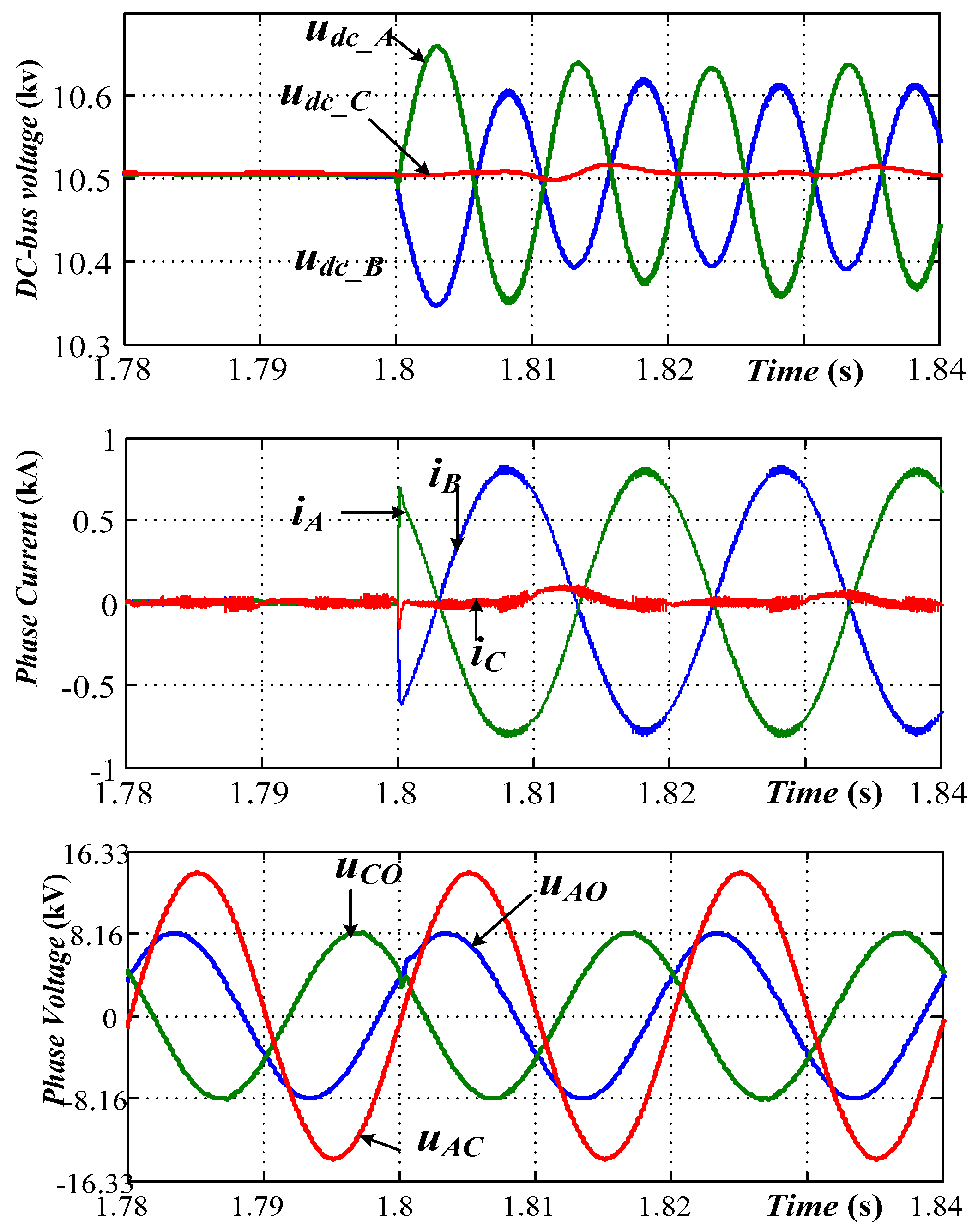
At t = 1.6 s, the proposed control system shown as Figure 5 is put into operation. And the DC-bus voltage reference of each phase is stepped from 10 kV to 10.5 kV at t = 1.6 s to verify the proposed DC voltage regulation, while the reactive current of A-phase is still kept zero.
(3)
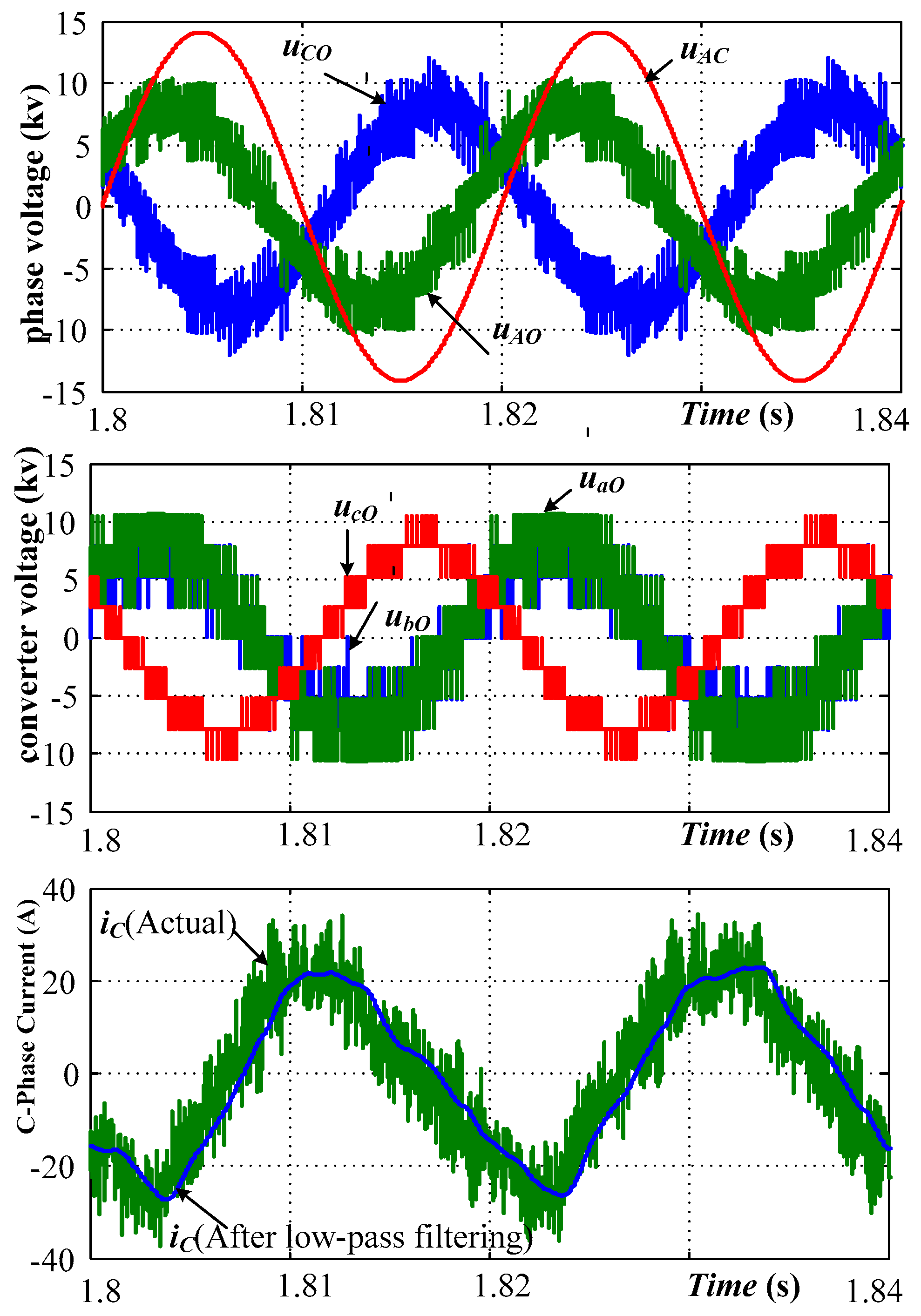
From the time, t = 1.8 s, the A-phase reactive current reference steps to its rated value.
The simulation results are shown in Figure 7, Figure 8, Figure 9 and Figure 10.
As shown in Figure 7, in the soft power-on process of 0–1.6 s, the DC-bus voltage of each phase converter rises smoothly to its expected value, and each current is far below the rated value. During this process, there are four stages: Firstly, both three phase converters were charging; secondly, A-phase converter charging; thirdly, C-phase converter charging; fourthly, no-load standby. This proves the feasibility of the proposed soft power-on method. It should be noted, in order to speed up the simulation so as to show the overall process in a limited time, the starting resistor in the simulation model is set to be small as 25 Ω. Generally, the actual soft-starting resistance is larger, thus the corresponding inrush current is smaller and the power-on process would be smoother.
As shown in Figure 8, during the transient process when the DC voltage reference steps at t = 1.6 s, three phase voltages are significantly different from the soft start process, but both their amplitude and phases are in line with their expectations, as shown Figure 4. The DC-bus voltages of three phase converters gradually rise to their set values and then remain stable, and each phase current is also gradually reduced from the initial sinusoidal waveform to near zero. During this period, both the amplitude and phase of A-phase current are different from that of B-phase current. This is because the B-phase current contains an additional component to regulate the C-phase DC-bus voltage.
As shown in Figure 9, during the third stage, three-phase currents quickly reach their steady state and then remain stable, while three-phase DC voltages remain stable. Among them, both A-phase and B-phase current quickly reach their rated value, their amplitudes are substantially equal, and their phases are approximately opposite. At the same time, the C-phase current is far less than the A-phase current. In Figure 9, the A-phase and C-phase voltage deals with a low-pass filter to show the low frequency components. In order to show the harmonic distortion in the proposed system, the original voltage and current without filtering are given in Figure 10. It can be seen that the fundamental component of the C-phase current is about 3% of the rated value (23 A/800 A = 2.9%).
As in Figure 10 shown, the original output voltages of three-phase converters are typical multi-level waveform. Because the number of submodules in this simulation are only four in each phase, there are various high-frequency ripples. It can be expected that when the submodules number increases, the output voltage would be smoother, thus the current ripple will be smaller. Although, there are obvious high-frequency components in A-phase and C-phase voltage, their fundamental components are still consistent with the expected values, indicating that these high-frequency harmonic components do not affect the feasibility of the testing system.

6. Conclusions

To address the factory test of high power STATCOM, a phase full-power testing method is present in this paper. By changing the port connection, three-phase STATCOM was reconstructed into a structure that two phases are in parallel, and then in series with the third-phase, and then connected to two phases of the rated voltage grid. Then, by rationally matching the three-phase voltage and current, the parallel two phases can run a reactive current hedging under both their rated voltage and rated current. The difficulty with this method is in maintaining the active balance of three-phase converters under this special structure. By mathematical modeling and theoretical analysis, it can be concluded that, the output voltage of the series phase converter cannot be simply set to the algebraic difference of the rated line voltage and phase voltage. Moreover, the reactive current components of the two parallel phases cannot be exactly offset, otherwise three phase convertors cannot maintain their active power balance. A specific combination of three-phase voltage and current is designed to maintain the steady operation of the system, and a corresponding control system is designed. Since the circuit configuration of the proposed testing system is different from the conventional STATCOM, this paper proposes a novel soft power-on method for this structure. The testing system was verified by a simulation in Matlab/Simulink. The simulation results show that, the proposed system can run stably, and two phases can operates at both, the rated phase voltage, and rated current, while the grid current is about 3% of the rated current. As a result, the three-phase STATCOM can experience a phase full-power test, phase-by-phase.
The proposed method has a certain similarity with the common method, where the two singe-phase convertors are in parallel and then connected to the single-phase grid, since it also employs two convertors to perform reactive power hedging. But the novelty of this method is that it uses the third-phase convertor of STATCOM to compensate for the voltage difference between the power supply voltage and the required phase voltage, so that the power voltage does not need to be directly equal to the required voltage for STATCOM testing. As a result, the existing power grid can be used to directly provide the test power, thereby avoiding the additional platform hardware and its cost. The main contribution of this paper is to clearly explain the constraint among three-phase voltage, current, and active power under such special structure, and solve the problem of charging and active power balance of three phase converters, and design a control system to realize it. This makes the aforementioned idea achievable.
Compared with other methods for the testing of STATCOM, the most prominent feature of this method is that its test platform only needs one tested STATCOM and a small capacity rated voltage grid, meaning no extra hardware is required and a lower test cost. Therefore, it is suitable for the whole-machine test of high-power STATCOM before its leaving the factory.

Author Contributions

Conceptualization, Q.H.; formal analysis, Q.H.; data curation, X.M.; writing-review and editing, Q.H. and Y.T.; software Y.Z. and S.Z.; project administration, B.L.

Funding

This research was partly funded by the science and technology project of State Grid Electric Corporation grant number 5216A016000P, and partly funded by the science and technology project of State Grid Hunan Electric Company Limited grant number 5216AF17000A.

Conflicts of Interest

The authors declare no conflict of interest.

References

  1. Liang, Y.; Nwankpa, C.O. A New type of STATCOM based on cascading voltage source inverters with phase-shifted unipolar SPWM. IEEE Trans. Ind. Appl. 1999, 35, 1447–1453. [Google Scholar]
  2. Schauder, C.; Gernhardt, M.; Stacey, E.; Lemak, T.; Gyugyi, L.; Cease, T.; Edris, A. Development of a ±100 MVAr static condenser for voltage control of transmission systems. IEEE Trans. Power Deliv. 1995, 10, 1486–1496. [Google Scholar] [CrossRef]
  3. Jain, A.; Joshi, K.; Behal, A.; Mohan, N. Voltage regulation with STATCOMs: Modeling, control and results. IEEE Trans. Power Deliv. 2006, 21, 726–735. [Google Scholar] [CrossRef]
  4. Rao, P.; Crow, M.; Yang, Z. STATCOM control for power system voltage control applications. IEEE Trans. Power Deliv. 2000, 15, 1311–1317. [Google Scholar] [CrossRef]
  5. Barrena, J.A.; Marroyo, L.; Vidal, M.Á.R.; Apraiz, J.R.T. Individual voltage balancing strategy for PWM cascaded H-bridge converter-based STATCOM. IEEE Trans. Ind. Electron. 2008, 55, 21–29. [Google Scholar] [CrossRef]
  6. Townsend, C.D.; Summers, T.J.; Betz, R.E. Phase-shifted carrier modulation techniques for cascaded H-bridge multilevel converters. IEEE Trans. Ind. Electron. 2015, 62, 6684–6696. [Google Scholar] [CrossRef]
  7. Singh, B.; Al-Haddad, K.; Saha, R.; Chandra, A. Static synchronous compensators (STATCOM): A review. IET Power Electron. 2009, 2, 297–324. [Google Scholar] [CrossRef]
  8. Fujii, K.; De Doncker, R.W. Optimization of soft-switched flying capacitor multi-level converters applied to STATCOMs. In Proceedings of the 2007 European Conference on Power Electronics and Applications, Aalborg, Denmark, 2–5 September 2007; pp. 1–10. [Google Scholar]
  9. Marchesoni, M.; Tenca, P. Diode-clamped multilevel converters: A practicable way to balance DC-link voltages. IEEE Trans. Ind. Electron. 2002, 49, 752–765. [Google Scholar] [CrossRef]
  10. Lv, J.; Gao, C.; Chen, S.; Liu, X.; Chen, Z. A novel STATCOM based on diode-clamped modular multilevel converters. IEEE Trans. Power Electron. 2017, 32, 5964–5977. [Google Scholar]
  11. Peng, F.; Lai, J. Dynamic performance and control of a static VAr generator using cascade multilevel inverters. IEEE Trans. Ind. Appl. 1997, 33, 748–755. [Google Scholar] [CrossRef]
  12. Cheng, Y.; Qian, C.; Crow, M.L.; Pekarek, S.; Atcitty, S. A comparison of diode-clamped and cascaded multilevel converters for a STATCOM with energy storage. IEEE Trans. Ind. Electron. 2006, 53, 1512–1521. [Google Scholar] [CrossRef]
  13. Lesnicar, A.; Marquardt, R. An innovative modular multilevel converter topology suitable for a wide power range. In Proceedings of the 2003 IEEE Bologna Power Tech Conference Proceedings, Bologna, Italy, 23–26 June 2003. [Google Scholar]
  14. Pereira, M.; Retzmann, D.; Lottes, J.; Wiesinger, M.; Wong, G. An MMC STATCOM for network and grid access applications. In Proceedings of the 2011 IEEE Trondheim Power Tech Conference, Trondheim, Norway, 13–23 June 2011; pp. 1–5. [Google Scholar]
  15. Inoue, S.; Yoshii, T.; Akagi, H. Control and performance of a transformerless cascade PWM STATCOM with star configuration. IEEE Trans. Ind. Appl. 2007, 43, 1041–1049. [Google Scholar]
  16. Bina, M.T. A Transformerless Medium-voltage STATCOM topology based on extended modular multilevel converters. IEEE Trans. Ind. Electron. 2011, 26, 1534–1545. [Google Scholar]
  17. Popavath, L.; Kaliannan, P. Photovoltaic-STATCOM with low voltage ride through strategy and power quality enhancement in a grid integrated wind-PV system. Electronics 2018, 7, 51. [Google Scholar] [CrossRef]
  18. Hossain, M.J.; Pota, H.R.; Ugrinovskii, V.A.; Ramos, R.A. Simultaneous STATCOM and pitch angle control for improved LVRT capability of fixed-speed wind turbines. IEEE Trans. Sustain. Energy 2010, 1, 142–151. [Google Scholar] [CrossRef]
  19. Park, J.; Yeo, S.; Choi, J. Development of ±400Mvar World Largest MMC STATCOM. In Proceedings of the 21st International Conference on Electrical Machines and Systems (ICEMS), Jeju, Korea, 7–10 October 2018. [Google Scholar]
  20. IEEE. Approved Draft Guide for the Functional Specifications for Transmission Static Synchronous Compensator (STATCOM) Systems; Institute of Electrical and Electronics Engineers (IEEE): New York, NY, USA; Available online: https://ieeexplore.ieee.org/document/STDAPE23348 (accessed on 3 July 2019).
  21. IEC. Voltage Sourced Converter (VSC) Valves for Static Synchronous Compensator (STATCOM): Electrical Testing; International Electrotechnical Commission (IEC): Geneva, Switzerland; Available online: https://webstore.iec.ch/publication/33207 (accessed on 3 July 2019).
  22. Guan, R.; Xue, Y.; Zhang, X.P. Advanced RTDS-based studies of the impact of STATCOM on feeder distance protection. J. Eng. 2018, 2018, 1038–1042. [Google Scholar] [CrossRef]
  23. Langston, J.; Qi, L.; Steurer, M.; Sloderbeck, M.; Liu, Y.; Xi, Z.; Mundkur, S.; Liang, Z.; Huang, A.Q.; Bhattacharya, S.; et al. In Testing of a controller for an ETO-based STATCOM through controller hardware-in-the-loop simulation. In Proceedings of the 2009 IEEE Power & Energy Society General Meeting, Calgary, AB, Canada, 1–8 July 2009. [Google Scholar]
  24. Liu, W.H.; Song, Q.; Zhang, D.J.; Chen, T.J.; Teng, L.T.; Zheng, D.R. Equivalent Tests of Links of 50 MVA STATCOM. Trans. China Electrotech. Soc. 2006, 21, 73–78. [Google Scholar]
  25. Woodhouse, M.L.; Donoghue, M.W.; Osborne, M.M. Type Testing of the GTO Valves for a Novel STATCOM Converter; IEE: London, UK, 2001; pp. 84–90. [Google Scholar]
  26. Zhang, Y.; Li, Q.; Zhang, S. Converter chain equivalent experiment for STATCOM of large capacity based on dc power supply. J. Power Supply 2017, 5, 94–99. [Google Scholar]
  27. Xie, Y.; Zhuo, F. Factory-used energy-saving testing method for STATCOM. Shanxi Power 2013, 11, 1–4. [Google Scholar]
  28. Liu, D.; Zhang, Y.; Ma, J.; Liu, X.; Gao, J. Current closed-loop test method for ±100 mvar high-voltage STATCOM in weak grid based on principle of equal potential. J. Power Supply 2018, 1, 119–124. [Google Scholar]
  29. Shi, Y.; Liu, B.; Shi, Y.; Duan, S. Individual phase current control based on optimal zero sequence current separation for a star-connected cascade STATCOM under unbalanced conditions. IEEE Trans. Power Electron. 2016, 31, 2009–2100. [Google Scholar] [CrossRef]
  30. Hatano, N.; Ise, T. Control scheme of cascaded H-bridge STATCOM using zero-sequence voltage and negative-sequence current. IEEE Trans. Power Deliv. 2010, 25, 543–550. [Google Scholar] [CrossRef]
  31. Li, B.; Yang, R.; Xu, D. Analysis of the phase-shifted carrier modulation for modular multilevel converters. IEEE Trans. Power Electron. 2015, 30, 297–310. [Google Scholar] [CrossRef]
  32. Jing, N.; He, Y. Phase-shifted suboptimal pulse-width modulation strategy for multilevel inverter. In Proceedings of the 2006 1st IEEE Conference on Industrial Electronics and Applications, Singapore, 24–26 May 2006. [Google Scholar]
  33. Deng, F.; Chen, Z. Voltage-balancing method for modular multilevel converters under phase-shifted carrier-based pulsewidth modulation. IEEE Trans. Power Electron. 2015, 62, 4158–4169. [Google Scholar] [CrossRef]
  34. Hagiwara, M.; Akagi, H. Control and experiment of pulse width modulated modular multilevel converters. IEEE Trans. Power Electron. 2009, 24, 1737–1746. [Google Scholar] [CrossRef]
  35. Qin, J.; Saeedifard, M. Reduced switching-frequency voltage balancing strategies for modular multilevel HVDC converters. IEEE Trans. Power Deliv. 2013, 4, 2403–2410. [Google Scholar] [CrossRef]
  36. Deng, F.; Chen, Z. A control method for voltage balancing in modular multilevel converters. IEEE Trans. Power Electron. 2014, 1, 66–76. [Google Scholar] [CrossRef]
  37. Han, C.; Huang, A.Q.; Liu, Y.; Chen, B. A generalized control strategy of per-phase DC voltage balancing for cascaded multilevel converter-based STATCOM. In Proceedings of the 2007 Power Electronics Specialists Conference, Orlando, FL, USA, 17–21 June 2007. [Google Scholar]
Figure 1. Circuit configuration of the proposed STATCOM testing method.
Electronics 08 00754 g001
Figure 2. Equivalent simplified circuit diagram of the proposed testing system.
Electronics 08 00754 g002
Figure 3. The basic voltage and current vector diagram of the testing system.
Electronics 08 00754 g003
Figure 4. The voltage and current vector diagram of the recommended voltage-current combination.
Electronics 08 00754 g004
Figure 5. The control system block of the proposed testing system.
Electronics 08 00754 g005
Figure 6. The flow diagram of soft power-on process for the individual phase full-load testing system.
Electronics 08 00754 g006
Figure 7. Simulation results of the proposed soft power-on process.
Electronics 08 00754 g007
Figure 8. Simulation results when the DC-bus voltage reference is step.
Electronics 08 00754 g008
Figure 9. Simulation results at the individual phase full-power operation state.
Electronics 08 00754 g009
Figure 10. Original voltage and current without filtering at the full-power operation state.
Electronics 08 00754 g010
Table 1. Parameters in the simulation model.
ParameterSymbolValue
Rated ratingSN±10 Mvar
Rated line voltageUlN10 kV
Rated phase voltageUPN5.7 kV
Rated currentIPN0.57 kA
Arm resistanceRA, RB, RC,0.1 Ω (0.01 pu)
Arm reactanceLA, LB, LC,3.2 mH (0.1 pu)
Submodule number in each phaseN4
DC-link capacitance of each submoduleCdc40 mF
Rated DC-bus voltage of each phase converterUdcN10.5 kV
Switching frequency of submodulefs500 Hz
Proportional coefficient of the current-loop controllerKp_c200
Proportional coefficient of the voltage-loop controllerKp_v4
Integral coefficient of the voltage-loop controllerKi_v50

