Torque Coordination Control of Hybrid Electric Vehicles Based on Hybrid Dynamical System Theory


Abstract
:1. Introduction
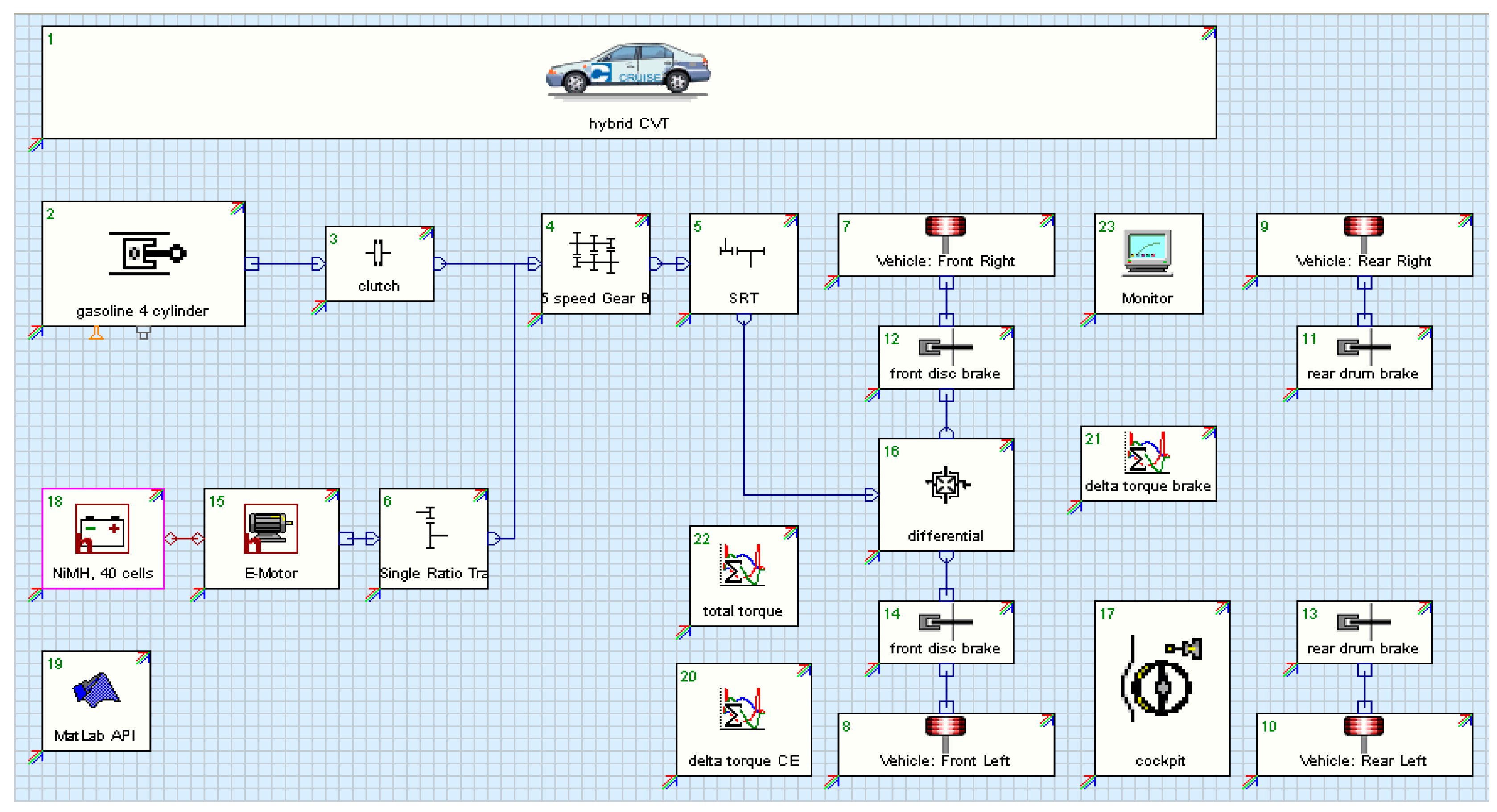
2. Description of the HEV Power System
2.1. Hybrid Dynamical System Theory
2.2. Description of Hybrid Power System Based on HDS Theory
3. Energy Management Strategy of HEV Based on Hybrid System Theory
3.1. EMS of HEV without Considering Torque Coordination
- (1)
- When the demand torque of the HEV is small and the state of charge (SOC) of the battery is high, the engine is turned off, and the electric drive mode is adopted;
- (2)
- When the SOC of the battery is too low or the demand torque is large, the engine is started, and the engine driving mode or the hybrid driving mode is adopted. According to the output torque of the motor and engine in Table 2, the motor operates in the maximum torque to use the electrical energy as much as possible, and the remaining demand torque is provided by the engine when the hybrid driving mode is adopted in the case of high-speed driving, acceleration and climbing. It is easy to understand that when the SOC is too low, in order to prevent the battery from being over-discharged, sometimes the vehicle is driven only by the engine, and the battery operates in the SOC maintenance mode.
- (3)
- When the SOC of the battery is low, the battery pack needs to meet the instantaneous input power requirement to achieve the regenerative braking.
3.2. EMS of HEV Considering Torque Coordination
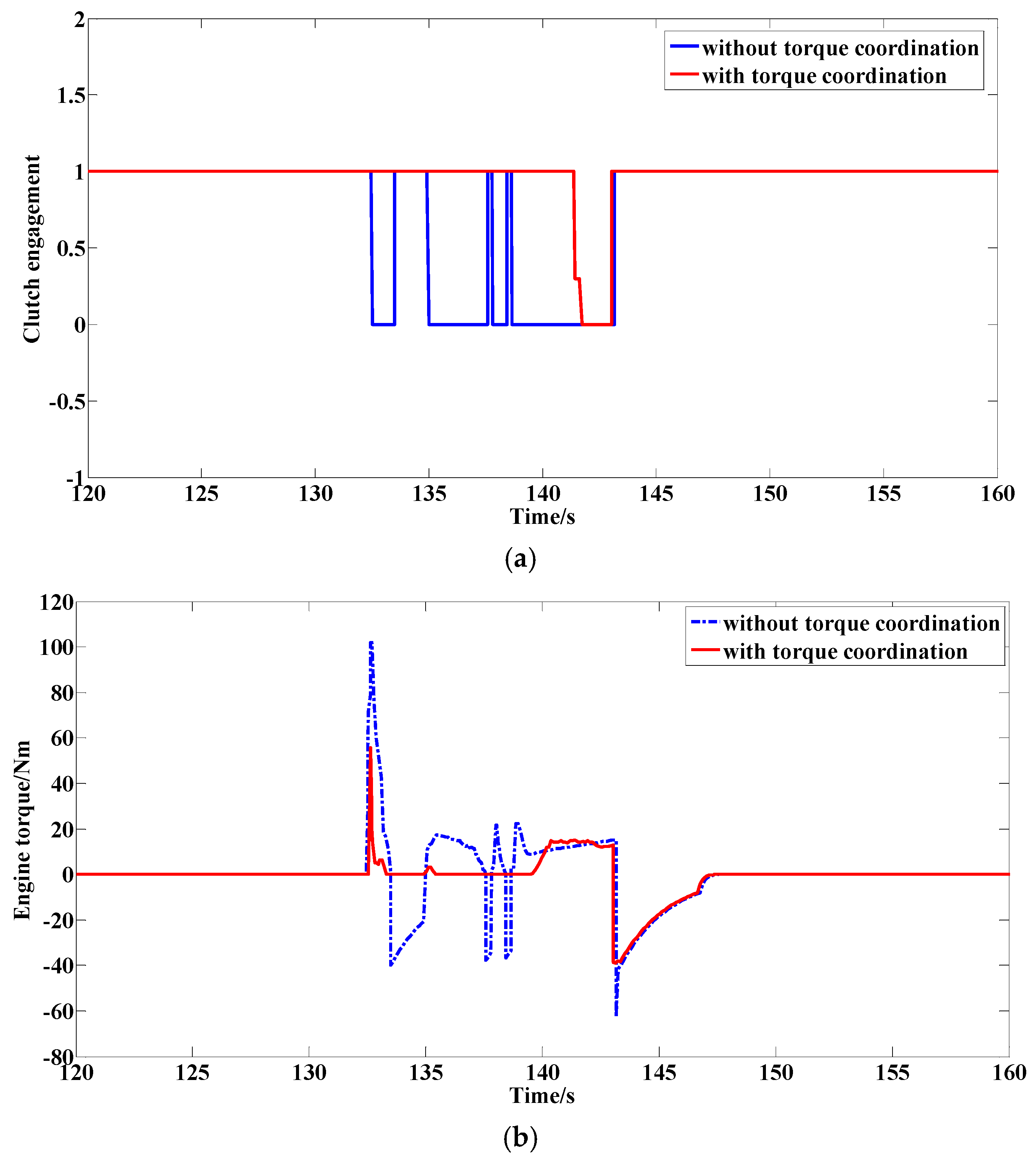
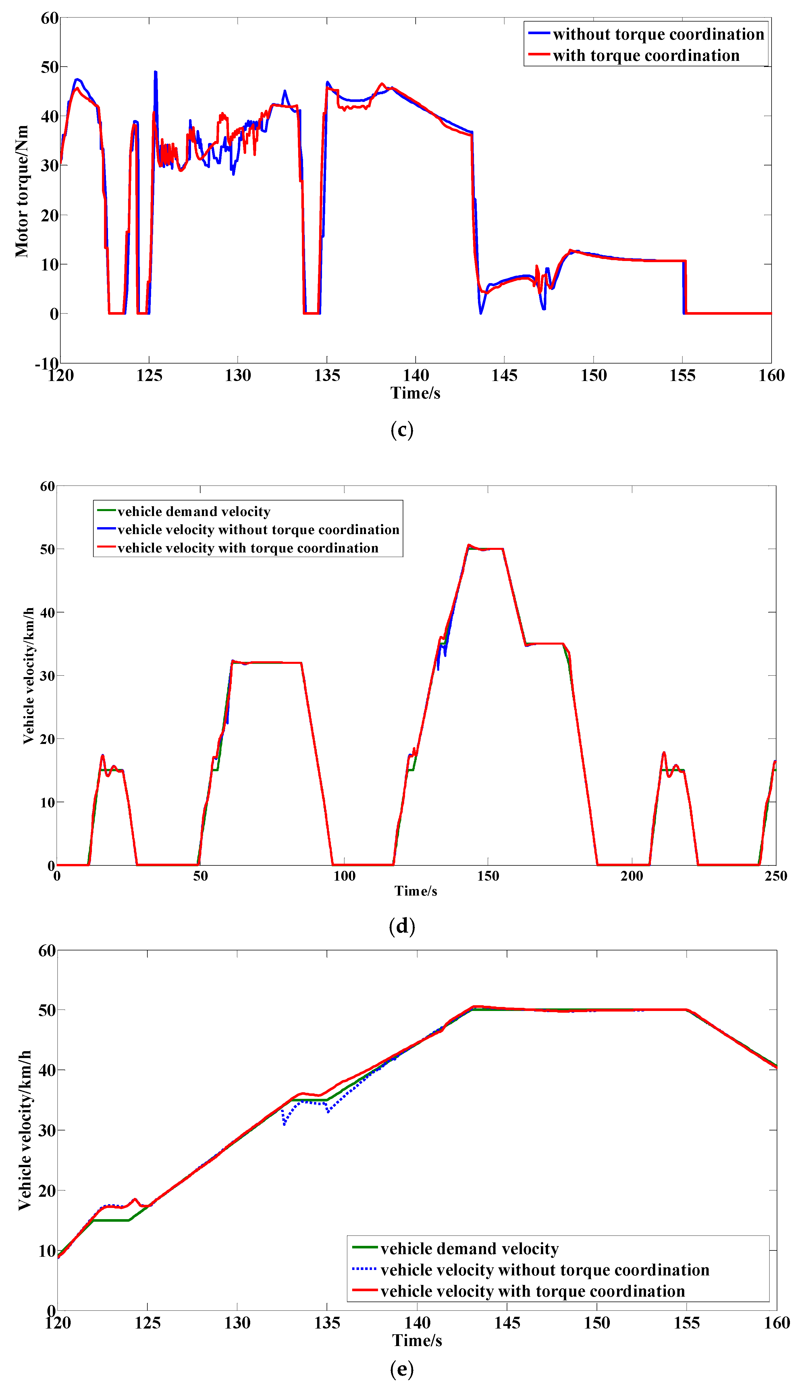
4. Results and Verification
5. Conclusions
Author Contributions
Funding
Acknowledgments
Conflicts of Interest
Abbreviations
| HEV | hybrid electric vehicle |
| BEV | battery electric vehicle |
| EV | electric vehicle |
| EMS | energy management strategy |
| HDS | hybrid dynamical system |
| HIOA | hybrid input and output automaton |
| DEDS | discrete event dynamical system |
| CVDS | continuous variable dynamical system |
| SOC | state of charge |
| Tr | vehicle demand torque of the HEV |
| Tm | output torque of motor |
| Te | output torque of engine |
| Tmmax | maximum instantaneous output torque of motor |
| SOCmin | setting lower limit value of the SOC of power battery |
| SOCmax | setting upper limit value of the SOC of power battery |
| we | engine speed |
| wm | motor speed |
| ud | discrete input variables |
| u1 | engagement states (YES/NO) of clutch |
| v | vehicle velocity |
| yc | continuous output variables |
| yd | discrete output variable |
References
- Chen, Z.; Hu, H.; Wu, Y.; Xiao, R.; Shen, J.; Liu, Y. Energy Management for a Power-Split Plug-In Hybrid Electric Vehicle Based on Reinforcement Learning. Appl. Sci. 2018, 8, 2494. [Google Scholar] [CrossRef]
- Zhang, Q.; Cui, N.; Li, K.; Shang, Y.; Zhang, C. Co-Simulation of Energy Management Strategy for Hybrid Electric Vehicle in AVL InMotion. In Proceedings of the Chinese Automation Congress, Jinan, China, 20–22 October 2017; pp. 4932–4937. [Google Scholar]
- Fu, Z.; Wang, B.; Song, X.; Liu, L.; Wang, X. Power-Split Hybrid Electric Vehicle Energy Management Based on Improved Logic Threshold Approach. Math. Probl. Eng. 2013, 2013, 840648. [Google Scholar] [CrossRef]
- Abronzini, U.; Attaianese, C.; D’Arpino, M.; Di Monaco, M.; Tomasso, G. Cost Minimization Energy Control Including Battery Aging for Multi-Source EV Charging Station. Electronics 2019, 8, 31. [Google Scholar] [CrossRef]
- Hu, J.; Jiang, X.; Jia, M.; Zheng, Y. Energy Management Strategy for the Hybrid Energy Storage System of Pure Electric Vehicle Considering Traffic Information. Appl. Sci. 2018, 8, 1266. [Google Scholar] [CrossRef]
- Xu, Q.; Mao, Y.; Zhao, M.; Cui, S. A Hybrid Electric Vehicle Dynamic Optimization Energy Management Strategy Based on a Compound-Structured Permanent-Magnet Motor. Energies 2018, 11, 2212. [Google Scholar] [CrossRef]
- Zhang, Q.; Fu, X.; Li, K.; Xing, G.; Zhang, C. Powertrain System Matching Optimization and Regenerative Braking Strategy for Pure Electric Vehicle. Acta Simul. Syst. Sin. 2016, 28, 600–609. [Google Scholar]
- Yang, Y.; Zhang, Y.; Tian, J.; Zhang, S. Research on a Plug-In Hybrid Electric Bus Energy Management Strategy Considering Drivability. Energies 2018, 11, 2177. [Google Scholar] [CrossRef]
- Gao, B.; Chen, H.; Li, J.; Tian, L.; Sanada, K. Observer-based Feedback Control During Torque Phase of Clutch-to-clutch Shift Process. Int. J. Veh. Des. 2012, 58, 93–108. [Google Scholar] [CrossRef]
- Yin, A.; Zhao, H. A Study on the Energy Control Strategy for Hybrid Electric Bus Based on Hybrid System Theory. Autom. Eng. 2010, 32, 98–102. [Google Scholar]
- Zhu, Y.; Tian, G.; Chen, Q.; Wu, H. Four-step Method to Design the Energy Management Strategy for Hybrid Vehicles. Chin. J. Mech. Eng. 2004, 40, 128–133. [Google Scholar] [CrossRef]
- Li, J.; Zhang, C. Study on Energy Management Strategy of Electric Vehicle Based on Hybrid System Theory. Acta Simul. Syst. Sin. 2006, 18, 2932–2935. [Google Scholar]
- Koprubasi, K.; Westervelt, E.R.; Rizzoni, G. Toward the Systematic Design of Controllers for Smooth Hybrid Electric Vehicle Mode Changes. In Proceedings of the American Control Conference, New York, NY, USA, 11–13 July 2007; pp. 2985–2990. [Google Scholar]
- Koprubasi, K.; Morbitzer, J.M.; Westervelt, E.R.; Rizzoni, G. Toward a Framework for the Hybrid Control of a Multi-mode Hybrid-electric Driveline. In Proceedings of the American Control Conference, Minneapolis, MN, USA, 14–16 June 2006; pp. 3296–3301. [Google Scholar]
- Banvait, H.; Hu, J.; Chen, Y. Supervisory Control of Plug-in Hybrid Electric Vehicle with Hybrid Dynamical System. In Proceedings of the IEEE International Electric Vehicle Conference, Greenville, SC, USA, 4–8 March 2012; pp. 1–7. [Google Scholar]
- Song, S.; Li, X.; Sun, Z. Analysis on the Control Strategy for Series Regenerative Braking Based on Hybrid System Theory. Autom. Eng. 2015, 37, 313–320. [Google Scholar]
- Zhang, C.; Li, S.; Cai, L. State Model and Object Model of Hybrid System. Acta Simul. Syst. Sin. 2008, 40, 562–566. [Google Scholar]
- Xue, L.; Liao, M.; Wei, C.; Chen, Z. Hybrid System and Its Modeling. Acta Simul. Syst. Sin. 2004, 16, 375–380. [Google Scholar]
- Zhang, H.; Li, P. Energy Management Strategy for Easy Series-parallel Hybrid Electric Bus Based on Hybrid Dynamical System Theory. Bus Technol. Res. 2011, 2, 26–28. [Google Scholar]
- Wu, J.; Zhang, C.; Cui, N.; Li, K. An Improved Energy Management Strategy for Parallel Hybrid Electric Vehicle. In Proceedings of the 6th World Congress on Intelligent Control & Automation, Dalian, China, 23 October 2006; pp. 8339–8343. [Google Scholar]
- Fu, X.; Wang, H.; Cui, N.; Zhang, C. Energy Management Strategy Based on the Driving Cycle Model for Plugin Hybrid Electric Vehicles. Abstr. Appl. Anal. 2014, 2014, 341096. [Google Scholar] [CrossRef]
- Sun, J.; Xing, G.; Liu, X.; Fu, X.; Zhang, C. A Novel Torque Coordination Control Strategy of a Single-Shaft Parallel Hybrid Electric Vehicle Based on Model Predictive Control. Math. Probl. Eng. 2015, 2015, 1–12. [Google Scholar] [CrossRef]
- Guo, L.; Ge, A.; Zhang, T.; Yue, Y. AMT Shift Process Control. Trans. Chin. Soc. Agric. Mach. 2003, 34, 1–3. [Google Scholar]
- Wang, T.; Mao, E.; Zhu, Z.; Song, Z.; Xie, B. Experimental Analysis of the Tractor Automatic Mechanism Transmission Dynamic Power Shifting Schedule. Trans. Chin. Soc. Agric. Mach. 2009, 40, 5–8. [Google Scholar]
- He, H.; Liu, Z.; Zhu, L.; Liu, X. Dynamic Coordinated Shifting Control of Automated Mechanical Transmissions without a Clutch in a Plug-in Hybrid Electric Vehicle. Energies 2012, 5, 3094–3109. [Google Scholar] [CrossRef]


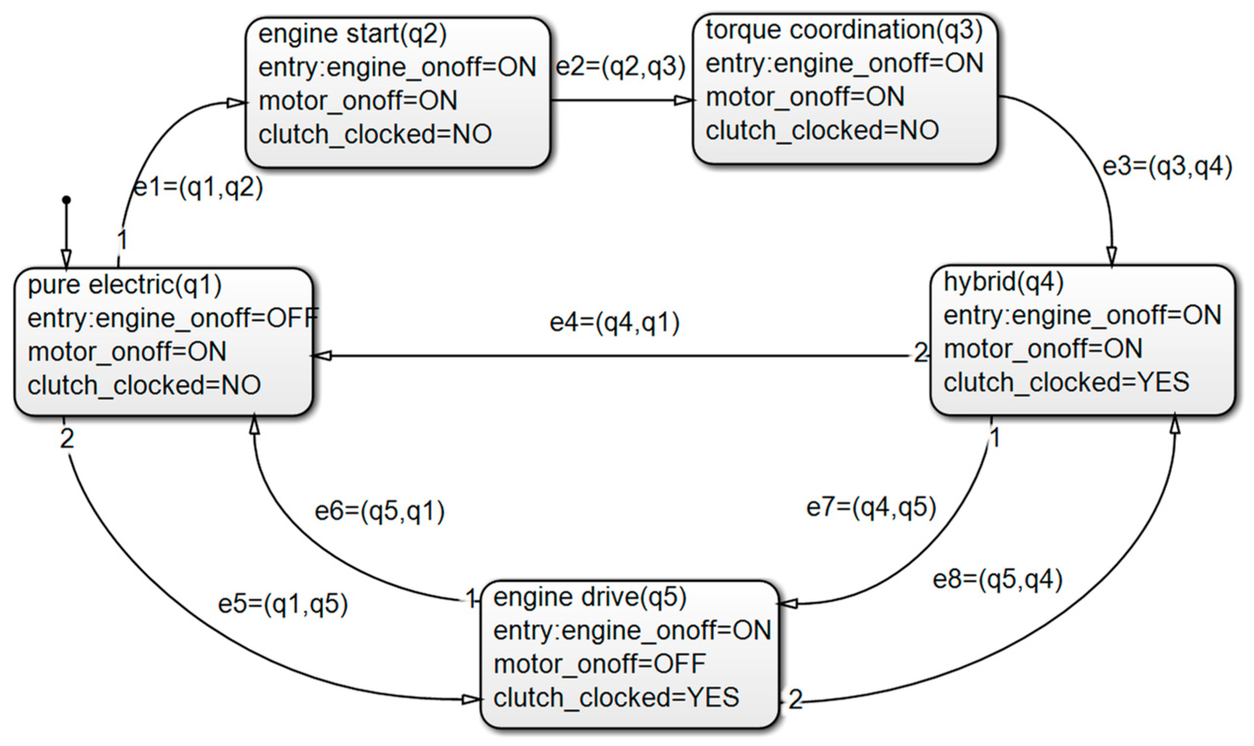
| Working State | Engine | Clutch | Motor | Description |
|---|---|---|---|---|
| electric drive | off | separation | work | motor drives vehicle separately |
| engine start | work | separation | work | motor drives vehicle separately and the engine starts |
| torque coordination | work | sliding friction | work | motor and engine jointly drive the vehicle, and clutch is in sliding friction |
| hybrid drive | work | combined | work | motor and engine jointly drive the vehicle, and clutch is fully integrated |
| engine drive | work | combined | off | engine drives vehicle separately |
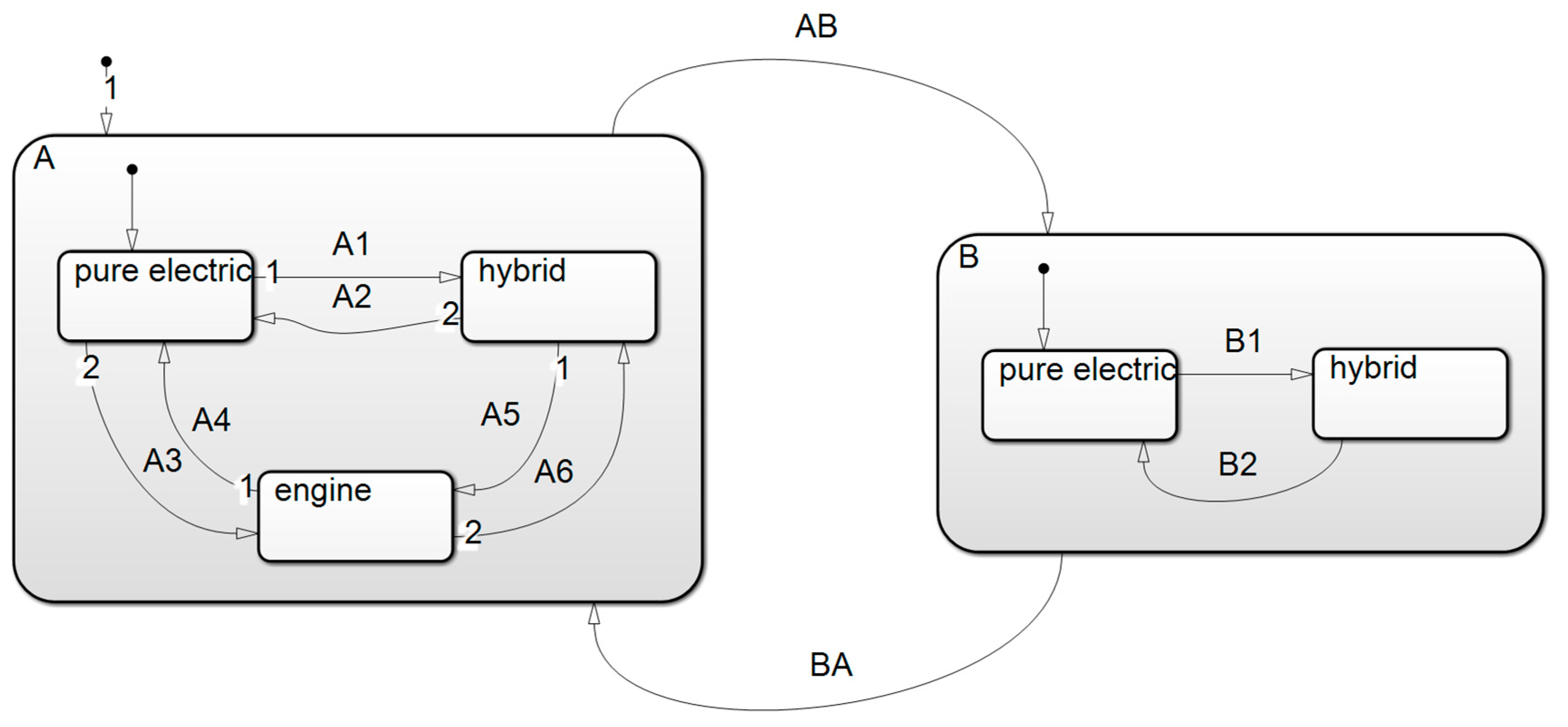
| T/State of Charge () | |||
|---|---|---|---|
| Code | Starting State | Switching Condition | Final State |
|---|---|---|---|
| AB | A () | , | B () |
| B1 | electric drive | hybrid drive | |
| B2 | hybrid drive | electric drive | |
| BA | B () | , | A () |
| A1 | electric drive | , | hybrid drive |
| A2 | hybrid drive | , | electric drive |
| A3 | electric drive | engine drive | |
| A4 | engine drive | , | electric drive |
| A5 | hybrid drive | engine drive | |
| A6 | engine drive | , | hybrid drive |
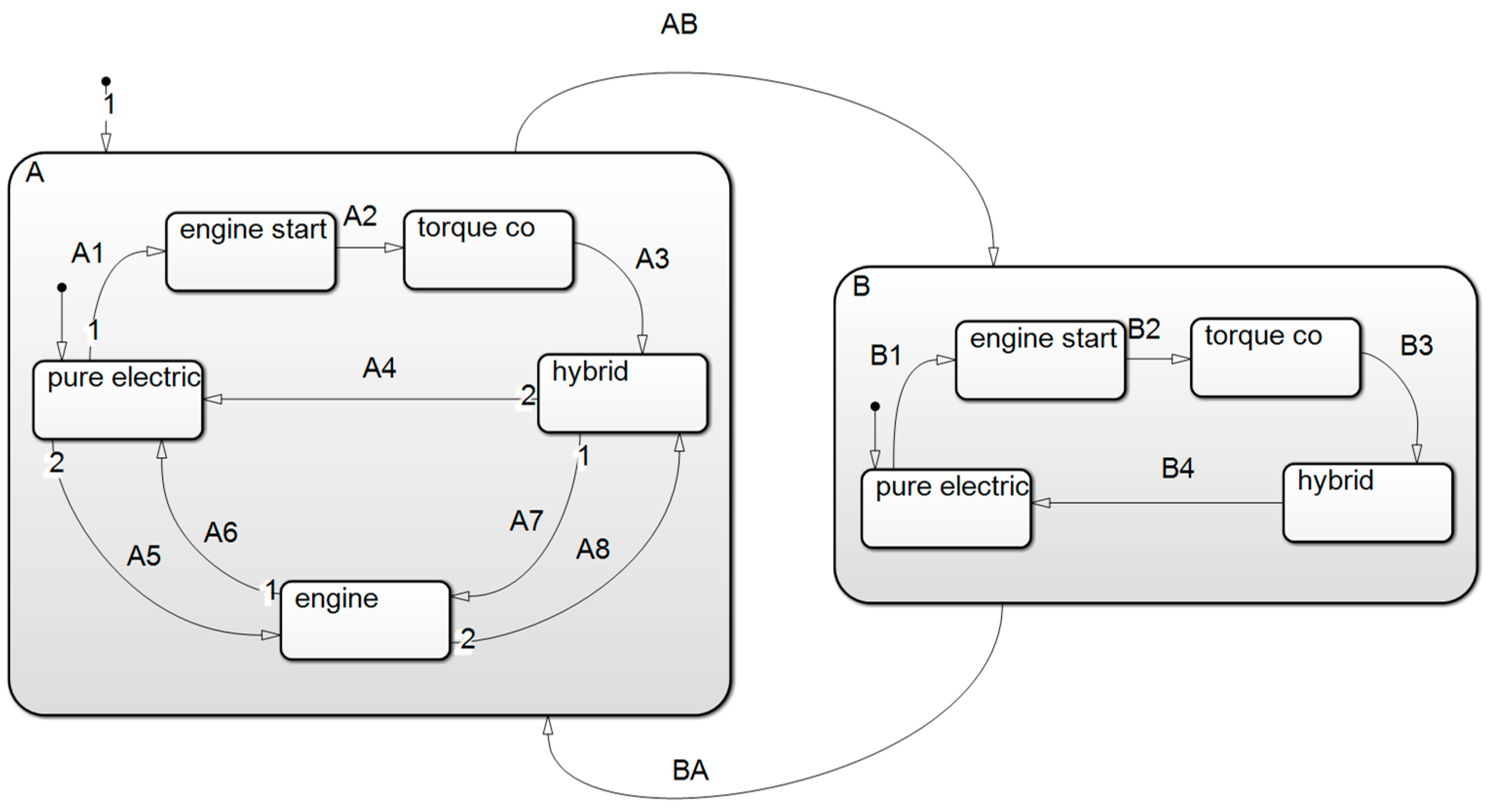
| Code | Starting State | Switching Condition | Final State |
|---|---|---|---|
| AB | A () | , | B () |
| B1 | electric drive | engine start | |
| B2 | engine start | torque coordination | |
| B3 | torque coordination | hybrid drive | |
| B4 | hybrid drive | electric drive | |
| BA | B () | , | A () |
| A1 | electric drive | , | engine start |
| A2 | engine start | torque coordination | |
| A3 | torque coordination | hybrid drive | |
| A4 | hybrid drive | , | electric drive |
| A5 | electric drive | engine drive | |
| A6 | engine drive | , | electric drive |
| A7 | hybrid drive | engine drive | |
| A8 | engine drive | , | hybrid drive |
© 2019 by the authors. Licensee MDPI, Basel, Switzerland. This article is an open access article distributed under the terms and conditions of the Creative Commons Attribution (CC BY) license (http://creativecommons.org/licenses/by/4.0/).
Share and Cite
Fu, X.; Zhang, Q.; Wang, C.; Tang, J. Torque Coordination Control of Hybrid Electric Vehicles Based on Hybrid Dynamical System Theory. Electronics 2019, 8, 712. https://doi.org/10.3390/electronics8060712
Fu X, Zhang Q, Wang C, Tang J. Torque Coordination Control of Hybrid Electric Vehicles Based on Hybrid Dynamical System Theory. Electronics. 2019; 8(6):712. https://doi.org/10.3390/electronics8060712
Chicago/Turabian StyleFu, Xiaoling, Qi Zhang, Chao Wang, and Jiyun Tang. 2019. "Torque Coordination Control of Hybrid Electric Vehicles Based on Hybrid Dynamical System Theory" Electronics 8, no. 6: 712. https://doi.org/10.3390/electronics8060712